EP4192633B1 - Ziehtisch für eine ziehmaschine - Google Patents
Ziehtisch für eine ziehmaschine Download PDFInfo
- Publication number
- EP4192633B1 EP4192633B1 EP20775929.1A EP20775929A EP4192633B1 EP 4192633 B1 EP4192633 B1 EP 4192633B1 EP 20775929 A EP20775929 A EP 20775929A EP 4192633 B1 EP4192633 B1 EP 4192633B1
- Authority
- EP
- European Patent Office
- Prior art keywords
- bench
- carriage
- rack
- base structure
- racks
- Prior art date
- Legal status (The legal status is an assumption and is not a legal conclusion. Google has not performed a legal analysis and makes no representation as to the accuracy of the status listed.)
- Active
Links
Images


Classifications
-
- B—PERFORMING OPERATIONS; TRANSPORTING
- B21—MECHANICAL METAL-WORKING WITHOUT ESSENTIALLY REMOVING MATERIAL; PUNCHING METAL
- B21C—MANUFACTURE OF METAL SHEETS, WIRE, RODS, TUBES, PROFILES OR LIKE SEMI-MANUFACTURED PRODUCTS OTHERWISE THAN BY ROLLING; AUXILIARY OPERATIONS USED IN CONNECTION WITH METAL-WORKING WITHOUT ESSENTIALLY REMOVING MATERIAL
- B21C1/00—Manufacture of metal sheets, wire, rods, tubes or like semi-manufactured products by drawing
- B21C1/16—Metal drawing by machines or apparatus in which the drawing action is effected by means other than drums, e.g. by a longitudinally-moved carriage pulling or pushing the work or stock for making metal sheets, rods or tubes
- B21C1/27—Carriages; Drives
- B21C1/28—Carriages; Connections of grippers thereto; Grippers
-
- B—PERFORMING OPERATIONS; TRANSPORTING
- B21—MECHANICAL METAL-WORKING WITHOUT ESSENTIALLY REMOVING MATERIAL; PUNCHING METAL
- B21C—MANUFACTURE OF METAL SHEETS, WIRE, RODS, TUBES, PROFILES OR LIKE SEMI-MANUFACTURED PRODUCTS OTHERWISE THAN BY ROLLING; AUXILIARY OPERATIONS USED IN CONNECTION WITH METAL-WORKING WITHOUT ESSENTIALLY REMOVING MATERIAL
- B21C1/00—Manufacture of metal sheets, wire, rods, tubes or like semi-manufactured products by drawing
- B21C1/16—Metal drawing by machines or apparatus in which the drawing action is effected by means other than drums, e.g. by a longitudinally-moved carriage pulling or pushing the work or stock for making metal sheets, rods or tubes
- B21C1/27—Carriages; Drives
- B21C1/30—Drives, e.g. carriage-traversing mechanisms; Driving elements, e.g. drawing chains; Controlling the drive
Definitions
- the present invention relates to the field of manufacturing metal products by means of drawing. More specifically, the invention relates to a drawing bench and a related drawing machine destined, in particular, to draw massive metal products.
- drawing is a forming process not involving material removal, by means of which a size reduction and/or a shape change is induced in the cross-section of a product or semi-finished product by forcing it to pass through a fixed orifice, referred to as a die, suitably sized and shaped so as to give the finished, drawn product, predetermined size and cross-sectional profile.
- the forced passage through the die is obtained by exerting a traction on the workpiece at the outlet side of the die.
- Drawing in particular cold drawing, is currently widely used for manufacturing various metal products of an elongated shape, such as for example wires, profiled bars, pipes, etc.
- drawing machines comprising a die, a guide bench placed on the inlet side of the die, i.e., upstream thereof with respect to the drawing direction, and a drawing bench placed on the outlet side of the die, i.e. downstream thereof with respect to the drawing direction.
- the guide bench is a usually a passive component and essentially serves to support and guide the piece upstream of the die.
- the drawing bench instead, is an active part of the drawing machine and comprises a base structure and a drawing carriage capable of translating on the base structure in the drawing direction. The drawing carriage is destined to receive and clamp one end of the workpiece downstream of the die and to apply the traction force required for drawing to the piece itself.
- the movement of the drawing carriage and therefore the traction force for the drawing are obtained by means of chain drive systems installed in the base structure of the drawing bench.
- Such systems comprise a chain extending in the drawing direction and circulating about at least two toothed pulleys, at least one of which being motorized, which are integral with the base structure.
- the drawing carriage is equipped with a hook connected as a pin to the frame thereof and adapted to engage with one of the pins of the chain, by means of which it is possible to kinematically couple/uncouple the drawing carriage and the chain.
- the components of the drive system are sized according to the maximum traction force to be delivered, which, in the case of drawing massive metal products, may also be very high, for example, in the order of a hundred tons. This has a negative impact on the volume, weight, cost, and commercial availability of the drive system components.
- chain drive systems are subjected to the so-called "pendulum” phenomenon, consisting of periodic oscillations of the tangential speed of a chain dragged by a toothed pulley, caused by corresponding variations in the tangential force acting on the chain pins which occur due to the periodic passage of the pins in the curved section of chain wrapped about the toothed pulley.
- Such tangential speed oscillations of the chain are transmitted to the drawing carriage and therefore have an impact on the traction force generated by the latter. If the amplitude thereof exceeds a certain threshold, surface defects (rings) appear on the drawn product which lead to commercial downgrading.
- a further drawback related to the use of chain drive systems is the noise thereof.
- a stationary noise component due to the circulation of the chain during the operation of the machine, but also an impulsive noise component, which is generated every time the hook of the drawing bench releases the chain at the end of a drawing stroke and the upper branch of the chain collapses by gravity on supports specially provided in the base structure of the drawing bench.
- this periodic impulsive component may reach or exceed the limit of 120 dB (pain threshold), so in known drawing machines it is also necessary to adopt specific acoustic insulation measures to comply with the relevant regulations in force, which have an impact on the manufacturing costs of known drawing machines.
- Document DE 29 05 790 A1 discloses a drawing bench of a drawing machine, and forms the basis for the preamble of claim 1.
- the present invention achieves at least one of such objects and other objects which will become apparent in light of the present description, by a drawing bench of a drawing machine, according to claim 1.
- the rack-pinion system is a mechanical transmission with rigid elements, i.e., a mechanical transmission in which, preferably, all the components which take part in the power transfer have a rigid, i.e., non-flexible, structure.
- the drawing bench according to the invention offers an easily scalable solution for the drive system of the drawing carriage, to the full advantage of the configuration and operational versatility of the drawing bench of the invention.
- power generation and transfer can be distributed among more than one motor. Therefore, both the motors and the other components of the mechanical transmission, in particular of the rack-pinion system, can be individually sized for lower loads than a maximum load corresponding to the maximum traction force which the drawing bench must deliver. This has a positive effect on the manufacturing and operating costs of the drawing bench of the invention.
- smaller sized components usually available on the market can be used for the drive system of the drawing carriage, on the other hand, the drawing bench can easily deliver traction forces lower than the maximum possible force without significant decreases in efficiency.
- a mechanical transmission with rigid elements also allows reducing the number of components and obtaining a higher overall transmission efficiency. This advantageously allows reducing the installed power with equal performance, and therefore contributes to the reduction of manufacturing and operating costs.
- the noise issues affecting the drawing machines of the known art due to the use of chain transmissions are substantially eliminated.
- the impulsive noise components related to the impact of the chain on the supports thereof, when it is released at the end of a drawing stroke are completely absent. Therefore, special soundproofing measures are not required in the drawing benches of the invention to comply with the noise thresholds imposed by the regulations in force, with a further advantage for the manufacturing costs of the drawing machines.
- the drawing bench of the invention there are also substantially no safety issues related to a possible sudden breakage of the components under load of the drive system of the drawing carriage, which affect the known drawing machines.
- the invention also relates to a drawing machine according to claim 13.
- the drawing bench 3 comprises:
- the drawing force exerted on said one or more racks 35 can be distributed between the at least two pinion 34-motor 36 pairs.
- the drawing force can be respectively distributed among the two or the three motors 36.
- the motors 36 and preferably also the pinions 34 may have a smaller size, and also have a significantly lower cost.
- a drawing bench 31 according to the invention allows greater versatility of use. Indeed, depending on the needs, only some of said at least two motors 36 can be activated. In other words, preferably, the motors 36 may be activated independently of each other.
- the motors 36 are, in particular, distinct from each other.
- the drawing bench 3 is, in particular, the drawing bench of a drawing machine 100 or, in other words, it is a drawing bench for a drawing machine.
- FIG. 1 diagrammatically shows a drawing machine in accordance with the invention, overall indicated with reference numeral 100.
- the drawing machine 100 is preferably, although not exclusively, used for drawing massive metal products or semi-finished products in the form of bars or pipes.
- the drawing machine 100 comprises, in sequence, along the drawing direction X, a guide bench 1, a die 2 and a drawing bench 3.
- drawing direction X is, in particular, straight.
- the guide bench 1 is configured so as to define a support base 10, in particular a continuous or discontinuous support base, for guiding, preferably passively, a workpiece 200 towards the die 2 in the drawing direction X.
- a support base 10 to support and guide the translation of the workpiece towards the die 2.
- Said means may, for example, comprise or consist of idle sliding rollers 11 or other equivalent means.
- the die 2 is mounted, preferably in a removable manner (i.e., so that it can be disassembled), in a corresponding support 20, preferably integral with the guide bench 1 and/or with the drawing bench 3.
- the shape and size of the die 2 determine the profile and the size of the cross-section of the drawn product.
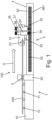
- the drawing bench 3 comprises a base structure 30, or support base, and a drawing carriage 31.
- the base structure 30 extends, in particular, in the drawing direction X.
- the base structure 30 has, in particular, a fixed position.
- the base structure 30 has a substantially beam-like shape.
- the drawing carriage 31 is capable of translating longitudinally, i.e., along the drawing direction X, on the base structure 30 itself.
- the base structure 30 defines a plane T, on which the drawing carriage 31 can translate.
- the plane T is also referred to as the translation plane T of the drawing carriage 31.
- the translation plane T is preferably defined by an upper surface of the base structure 30.
- rolling or sliding support and/or guiding means are provided, such as for example wheels 32, by means of which the drawing carriage 31 and the base structure 30 can cooperate with each other.
- said rolling or sliding support and/or guiding means are fastened to the drawing carriage 31.
- the drawing carriage 31 can cooperate with the base structure 30 at only one side of the base structure 30 ( Figure 1 ), or, preferably, it can be configured so as to embrace, i.e., surround, the base structure 30 on at least two, more preferably three or at least three, sides thereof ( Figures 2 , 3 ).
- the drawing carriage 31 comprises a clamping device 33 adapted to receive and clamp one end of the workpiece 200 from the downstream side of the die 2.
- the drawing carriage 31, translating away from the die 2 along the drawing direction X is capable of applying to the workpiece 200 the traction force required to pass it through the die 2, thus causing the drawing thereof.
- the length of the base structure 30 and the length of the translation stroke of the drawing carriage 31 are designed according to the length of the workpieces 200, i.e., of the products to be drawn with the drawing machine 100.
- the drawing bench 3 also comprises a drive system, or movement system, of the drawing carriage 31.
- the drive system comprises or consists of a rack-pinion system.
- the drawing bench 3 comprises a rack-pinion system adapted to translate the drawing carriage 31 along said predetermined direction X on the base structure 30.
- said rack-pinion system is provided, i.e., a rack-and-pinion transmission.
- two motors 36 and two pinions 34 are provided.
- One of the two motors 36 is adapted to drive one of the two pinions 34, and the other of the two motors 36 is adapted to drive the other of the two pinions 34.
- the pinions 34 are engaged with the same rack 35 of said one or more racks.
- only one rack 35 is preferably provided, as in the examples shown.
- Each rack 35 of said one or more racks extends longitudinally parallel to the drawing direction X.
- each motor 36 is of the electric type.
- each motor 36 comprises a respective shaft (not shown), in particular a respective motor shaft, adapted to rotate and to transmit the rotation motion to the respective pinion 34.
- each motor 36 in particular the shaft of each motor 36, is connected to the respective pinion 34 by means of a gear reducer 37.
- Each motor 36 and the respective gear reducer 37 preferably form or are part of a respective gearmotor assembly.
- the motors 36 in particular the gearmotor assemblies, substantially rest on the drawing carriage 31.
- the motors 36 preferably have a position such that the rotation axes of the respective shafts are substantially parallel to the translation plane T of the drawing carriage 31, and therefore perpendicular to the rotation axes R of the pinions 34.
- the gear reducers 37 interposed between each motor 36 and the respective pinion 34 are angular.
- each pinion 34 is integral, in particular integral in translation, with the drawing carriage 31 and said one or more racks 35 are integral with the base structure 30.
- each pinion 34 can rotate about the respective rotation axis R thereof ( Figure 3 ), and the rotation of the pinions 34 causes the translation of the drawing carriage 31 and also of the pinions 34 together with the drawing carriage 31.
- the motors 36 are advantageously mounted on board the drawing carriage 31, i.e., they can translate together with the drawing carriage 31, thus reducing the volume of the drawing machine 100 on the ground.
- said at least two pinions 34 and said one or more racks 35 cooperate with each other on at least one plane, for example one plane, parallel to the drawing direction X and preferably substantially perpendicular to the translation plane T of the drawing carriage 31 on the base structure 30.
- the rack 35 is preferably arranged on a longitudinal, preferably external, side 301 of the base structure 30.
- Said longitudinal side 301 in particular, extends perpendicularly to the translation plane T of the drawing carriage 31.
- the pinions 34 preferably extend in a cantilever manner from the drawing carriage 31 at the same longitudinal side 301 of the base structure 30, with a respective rotation axis R perpendicular to the translation plane T of the drawing carriage 31.
- the aforesaid longitudinal side 301, or side wall 301 is in particular a wall which extends substantially perpendicularly to the translation plane T.
- the arrangement of the one or more racks 35 on one or more side walls, for example, of the base structure 30, allows reducing the overall volume as compared to a solution in which the one or more racks are arranged on an upper surface of the base structure 30, the latter however being a possible variant.
- the one or more racks 35 may also be mounted on an internal longitudinal side, i.e., on an internal surface of a side wall, of the base structure 30.
- a drawing machine 100 may be adapted to deliver high traction forces, for example, at least 100 tons, for example, equal to about 100 tons.
- each pinion 34-motor 36 pair (in particular, each pinion 34 and the related gearmotor assembly) can be configured to withstand only a fraction of the maximum load corresponding to the maximum traction force which can be generated in the drawing machine 100.
- each pinion 34-motor 36 pair may be configured to withstand one third of said maximum load.
- operating modes may be provided in which only some (for example, one or more) of the pinions 34 are active, while the others (one or more) remain idle and do not transfer power, so that the drawing machine 100 may deliver in a flexible manner and always with high efficiency even traction forces below the maximum traction force.
- two or more racks 35 may be provided.
- a rack may be provided for each pinion 34, and each pinion 34 is engaged with a respective rack 35.
- two pinions 34 may be engaged with a rack 35 and the other two pinions 34 may be engaged with another rack 35.
- a first rack and a second rack of said at least two racks are fastened to the same side wall 301 of the base structure 30; or a first rack is fastened to a first side wall 301 of the base structure 30, and a second rack is fastened to a second side wall of the base structure 30, opposite to said first side wall 301.
- each rack 35 may be fastened to the external surface or to the internal surface of the respective side wall of the base structure 30.
- the pinions 34 and the related motors 36 may be appropriately distributed among the racks 35, preferably so as to ensure a force transmission symmetrical with respect to the drawing direction X.
- said one or more racks 35 may be integral with the drawing carriage 31 and said at least two pinions 34 may be integral with the base structure 30.
- said one or more racks 35 are preferably fastened to a side wall of the drawing carriage 31.
- a first rack and a second rack of said at least two racks may be fastened to the same side wall of the drawing carriage 31; or a first rack is fastened to a first side wall of the drawing carriage, and a second rack is fastened to a second side wall of the drawing carriage 31, opposite to said first side wall.
- the invention may also be implemented in multi-line drawing machines, adapted to simultaneously draw multiple workpieces 200 in parallel.
- the drawing force can be advantageously distributed among more than one motor 36, so as to reduce the size and generally the cost of each motor, in particular as compared to when only one motor is provided.
- flexible transmission elements, in particular chains, for driving the drawing carriage are preferably absent. This allows for a more versatile and efficient operation, a reduction in manufacturing and operating costs and in noise levels, and the obtainment of high-quality drawn products.
- the rack-pinion system for driving, in particular for moving, the drawing carriage 31 is a particularly simple, compact, robust and easy-to-maintain technical solution for moving the drawing carriage 31 and generating the traction force required for the drawing, preferably using only rigid transmission elements. Furthermore, as already explained, this solution is easily scalable, as the traction force can be increased by increasing the number of active pinions on the rack (or on the racks).
- the number of motors 36 and of the related pinions 34 may be selected according to the needs, and may be at least equal to two, for example two, at least equal to three, for example three, at least equal to four, for example four, and it may even be more than four.
- the motors 36 are equal or substantially equal to one another; and/or the pinions 34 are equal or substantially equal to one another.
Landscapes
- Engineering & Computer Science (AREA)
- Mechanical Engineering (AREA)
- Metal Extraction Processes (AREA)
- Shaping By String And By Release Of Stress In Plastics And The Like (AREA)
Claims (14)
- Ziehtisch (3) für eine Ziehmaschine (100), umfassend:- einen Ziehschlitten (31), der entlang einer vorbestimmten Richtung (X) auf einer Grundstruktur (30) verschiebbar ist,- ein Zahnstangen-Ritzel-System, das dazu geeignet ist, den Ziehschlitten (31) entlang der vorbestimmten Richtung (X) auf der Grundstruktur (30) zu verschieben;wobei das Zahnstangen-Ritzel-System umfasstmindestens zwei Motoren (36),mindestens zwei Ritzel (34),und eine oder mehrere Zahnstangen (35);wobei jeder Motor (36) dazu geeignet ist, ein jeweiliges Ritzel (34) anzutreiben;wobei der Ziehtisch dadurch gekennzeichnet ist, dassdie Drehachse (R) jedes Ritzels (34) im Wesentlichen orthogonal zu einer Verschiebungsebene (T) des Ziehschlittens (31) auf der Grundstruktur (30) ist.
- Ziehtisch (3) nach Anspruch 1, wobei die mindestens zwei Ritzel (34) mit der gleichen Zahnstange (35) der einen oder mehreren Zahnstangen in Eingriff stehen; wobei vorzugsweise nur eine Zahnstange (35) vorgesehen ist.
- Ziehtisch (3) nach Anspruch 1, wobei jedes Ritzel (34) mit einer jeweiligen Zahnstange (35) in Eingriff steht; wobei vorzugsweise zwei oder mehr Zahnstangen vorgesehen sind.
- Ziehtisch (3) nach einem der vorhergehenden Ansprüche, wobei die mindestens zwei Ritzel (34) einstückig mit dem Ziehschlitten (31) sind und die eine oder mehreren Zahnstangen (35) einstückig mit der Grundstruktur (30) ist/sind; oder wobei die mindestens zwei Ritzel (34) einstückig mit der Grundstruktur (30) sind und die eine oder mehreren Zahnstangen (35) einstückig mit dem Ziehschlitten (31) ist/sind.
- Ziehtisch (3) nach einem der vorhergehenden Ansprüche, wobei die eine oder mehreren Zahnstangen (35) an einer Seitenwand (301) der Grundstruktur (30) befestigt ist/sind; oder wobei die eine oder mehreren Zahnstangen an einer Seitenwand des Ziehschlittens befestigt ist/sind.
- Ziehtisch (3) nach einem der vorhergehenden Ansprüche, wobei das Zahnstangen-Ritzel-System mindestens zwei Zahnstangen umfasst,- wobei eine erste Zahnstange und eine zweite Zahnstange der mindestens zwei Zahnstangen an der gleichen Seitenwand der Grundstruktur oder des Ziehschlittens befestigt sind,- oder wobei eine erste Zahnstange an einer ersten Seitenwand der Grundstruktur oder des Ziehschlittens befestigt ist und eine zweite Zahnstange an einer zweiten Seitenwand der Grundstruktur oder des Ziehschlittens, die der ersten Seitenwand gegenüberliegt, befestigt ist.
- Ziehtisch (3) nach einem der vorhergehenden Ansprüche, wobei die mindestens zwei Ritzel (34) und die eine oder mehreren Zahnstangen (35) auf mindestens einer Ebene, vorzugsweise einer Ebene, die im Wesentlichen senkrecht zu einer Verschiebungsebene (T) des Ziehschlittens (31) auf der Grundstruktur (30) verläuft, miteinander zusammenwirken.
- Ziehtisch (3) nach einem der vorhergehenden Ansprüche, wobei das Zahnstangen-Ritzel-System mindestens drei Motoren (36) und mindestens drei Ritzel (34) umfasst; vorzugsweise drei Motoren (36) und drei Ritzel (34).
- Ziehtisch (3) nach einem der vorhergehenden Ansprüche, wobei jeder Motor (36) mittels eines Vorgeleges (37) mit einem jeweiligen Ritzel (34) verbunden ist und/oder wobei jeder Motor (36) ein Elektromotor ist.
- Ziehtisch (3) nach einem der vorhergehenden Ansprüche, wobei jeder Motor (36) eine jeweilige Welle mit einer Drehachse senkrecht zu der Drehachse (R) des jeweiligen Ritzels (34) aufweist.
- Ziehtisch (3) nach einem der vorhergehenden Ansprüche, wobei die Motoren (36) an Bord des Ziehschlittens (31) montiert sind.
- Ziehtisch (3) nach einem der vorhergehenden Ansprüche, wobei der Ziehschlitten (31) die Grundstruktur (30) an mindestens zwei Seiten, vorzugsweise drei oder an mindestens drei Seiten, umgreift.
- Ziehmaschine (100), die einen Ziehtisch (3) nach einem der vorhergehenden Ansprüche umfasst.
- Ziehmaschine (100) nach Anspruch 13, die in dieser Reihenfolge entlang der Ziehrichtung (X) einen Führungstisch (1), eine Matrize (2) und den Ziehtisch (3) umfasst; wobei der Führungstisch (1) vorzugsweise mit Mitteln (11) versehen ist, die dazu geeignet sind, die Verschiebung eines Werkstücks (200) in Richtung der Matrize (2) zu unterstützen und zu führen.
Applications Claiming Priority (1)
| Application Number | Priority Date | Filing Date | Title |
|---|---|---|---|
| PCT/IB2020/057393 WO2022029469A1 (en) | 2020-08-05 | 2020-08-05 | Drawing bench for drawing machine |
Publications (3)
| Publication Number | Publication Date |
|---|---|
| EP4192633A1 EP4192633A1 (de) | 2023-06-14 |
| EP4192633C0 EP4192633C0 (de) | 2024-10-02 |
| EP4192633B1 true EP4192633B1 (de) | 2024-10-02 |
Family
ID=72613940
Family Applications (1)
| Application Number | Title | Priority Date | Filing Date |
|---|---|---|---|
| EP20775929.1A Active EP4192633B1 (de) | 2020-08-05 | 2020-08-05 | Ziehtisch für eine ziehmaschine |
Country Status (5)
| Country | Link |
|---|---|
| US (1) | US12434286B2 (de) |
| EP (1) | EP4192633B1 (de) |
| CN (1) | CN116323026A (de) |
| ES (1) | ES2997009T3 (de) |
| WO (1) | WO2022029469A1 (de) |
Families Citing this family (2)
| Publication number | Priority date | Publication date | Assignee | Title |
|---|---|---|---|---|
| AT524974B1 (de) * | 2021-04-19 | 2025-06-15 | Most Technik Gmbh | Ziehbank |
| EP4501481A1 (de) * | 2023-08-04 | 2025-02-05 | La Farga Yourcoppersolutions, S.A. | Drahtziehvorrichtung in einer ein- oder mehrdrahtmaschine oder in einem drahtziehverfahren |
Family Cites Families (14)
| Publication number | Priority date | Publication date | Assignee | Title |
|---|---|---|---|---|
| US2243382A (en) | 1939-03-08 | 1941-05-27 | Tube Ind Participation Ltd | Push bench apparatus |
| US2674367A (en) | 1948-08-30 | 1954-04-06 | Metal Manufactures Ltd | Drawbench |
| DE1777110B2 (de) * | 1968-09-07 | 1970-11-19 | ||
| SU510286A1 (ru) | 1972-09-21 | 1976-04-15 | Волочильный стан | |
| SU489562A2 (ru) | 1974-07-15 | 1975-10-30 | Воронежский Ордена Ленина Завод Тяжелых Механических Прессов | Устройство дл подачи листовых заготовок в пресс |
| DE2451105A1 (de) | 1974-10-28 | 1976-04-29 | Kocks Gmbh Friedrich | Antrieb fuer eine zahnstange |
| DE2739812A1 (de) | 1977-09-03 | 1979-03-08 | Forst Maschf Oswald | Ziehmaschine |
| SU1088195A1 (ru) | 1979-01-02 | 1985-09-30 | Государственный научно-исследовательский и проектный институт сплавов и обработки цветных металлов "Гипроцветметобработка" | Волочильный стан |
| DE2905790A1 (de) | 1979-02-15 | 1980-08-28 | Kocks Gmbh Friedrich | Rohrstossbank |
| SU916007A1 (ru) | 1980-08-04 | 1982-03-30 | Valentin F Razin | Натяжное устройство ленты трубоформовочного стана i |
| CN105032961A (zh) | 2015-07-20 | 2015-11-11 | 东莞市方荣精机工业有限公司 | 一种齿轮齿条拉拔机 |
| CN106881363A (zh) | 2017-03-14 | 2017-06-23 | 西安麦特沃金液控技术有限公司 | 齿轮齿条式连续拉制多种截面形状制品的方法及拉拔机 |
| CN208213953U (zh) * | 2018-01-26 | 2018-12-11 | 天津百吉晟源金属制品有限公司 | 一种全自动拔丝机 |
| CN210876787U (zh) * | 2019-11-01 | 2020-06-30 | 邢台金诚特殊钢制造有限公司 | 一种高表面精度不锈钢联合拉拔线 |
-
2020
- 2020-08-05 WO PCT/IB2020/057393 patent/WO2022029469A1/en not_active Ceased
- 2020-08-05 CN CN202080104477.8A patent/CN116323026A/zh active Pending
- 2020-08-05 US US18/040,086 patent/US12434286B2/en active Active
- 2020-08-05 EP EP20775929.1A patent/EP4192633B1/de active Active
- 2020-08-05 ES ES20775929T patent/ES2997009T3/es active Active
Also Published As
| Publication number | Publication date |
|---|---|
| EP4192633C0 (de) | 2024-10-02 |
| US12434286B2 (en) | 2025-10-07 |
| EP4192633A1 (de) | 2023-06-14 |
| CN116323026A (zh) | 2023-06-23 |
| US20230271239A1 (en) | 2023-08-31 |
| WO2022029469A1 (en) | 2022-02-10 |
| ES2997009T3 (en) | 2025-02-13 |
Similar Documents
| Publication | Publication Date | Title |
|---|---|---|
| EP4192633B1 (de) | Ziehtisch für eine ziehmaschine | |
| EP3178582B1 (de) | Werkstückfördervorrichtung für eine pressmaschine | |
| CN106185190A (zh) | 一种宽度可调的传动装置 | |
| CN107310909B (zh) | 一种摩擦式物流运输线体装置 | |
| CN111390061B (zh) | 一种金属线材矫直设备 | |
| US5819584A (en) | Linear drive system | |
| RU2818938C1 (ru) | Рабочий стол для волочильного стана | |
| CN213772127U (zh) | 一种钢丝绳去应力装置 | |
| IT201900008901A1 (it) | Banco di trafilatura per macchina trafilatrice | |
| CN212385095U (zh) | 一种用于棒材机械加工的自动进料装置 | |
| CN101780509A (zh) | 液压箍筋机上的驱动装置 | |
| CN213444615U (zh) | 一种异型钢加工的输送平台 | |
| CN219703801U (zh) | 一种圆管切割工作台 | |
| CN105035851A (zh) | 一种成品钢绞线束的推送机 | |
| CN209766646U (zh) | 一种横滚支撑传动结构 | |
| CN212375326U (zh) | 一种联合拉拔机的在线退火装置 | |
| CN100366353C (zh) | 往复式钢管拔管机 | |
| DE102010025686B4 (de) | Teleskop-Fördervorrichtung | |
| CN212419207U (zh) | 一种开式卷板机用上辊装置 | |
| AT409855B (de) | Vorrichtung zum auf- und ausspulen eines seiles einer seilwinde | |
| CN217457458U (zh) | 一种管件快速移位机构 | |
| CN211413184U (zh) | 一种稳定静音的邦迪管制管机组 | |
| CN222175447U (zh) | 一种金属软管切割用矫直装置 | |
| CN220077480U (zh) | 一种用于锯条生产的高速传动装置 | |
| CN219688421U (zh) | 一种异形钨钢模具的双层式输送装置 |
Legal Events
| Date | Code | Title | Description |
|---|---|---|---|
| STAA | Information on the status of an ep patent application or granted ep patent |
Free format text: STATUS: UNKNOWN |
|
| STAA | Information on the status of an ep patent application or granted ep patent |
Free format text: STATUS: THE INTERNATIONAL PUBLICATION HAS BEEN MADE |
|
| PUAI | Public reference made under article 153(3) epc to a published international application that has entered the european phase |
Free format text: ORIGINAL CODE: 0009012 |
|
| STAA | Information on the status of an ep patent application or granted ep patent |
Free format text: STATUS: REQUEST FOR EXAMINATION WAS MADE |
|
| 17P | Request for examination filed |
Effective date: 20230228 |
|
| AK | Designated contracting states |
Kind code of ref document: A1 Designated state(s): AL AT BE BG CH CY CZ DE DK EE ES FI FR GB GR HR HU IE IS IT LI LT LU LV MC MK MT NL NO PL PT RO RS SE SI SK SM TR |
|
| P01 | Opt-out of the competence of the unified patent court (upc) registered |
Effective date: 20230630 |
|
| DAV | Request for validation of the european patent (deleted) | ||
| DAX | Request for extension of the european patent (deleted) | ||
| GRAP | Despatch of communication of intention to grant a patent |
Free format text: ORIGINAL CODE: EPIDOSNIGR1 |
|
| STAA | Information on the status of an ep patent application or granted ep patent |
Free format text: STATUS: GRANT OF PATENT IS INTENDED |
|
| INTG | Intention to grant announced |
Effective date: 20240318 |
|
| GRAS | Grant fee paid |
Free format text: ORIGINAL CODE: EPIDOSNIGR3 |
|
| GRAA | (expected) grant |
Free format text: ORIGINAL CODE: 0009210 |
|
| STAA | Information on the status of an ep patent application or granted ep patent |
Free format text: STATUS: THE PATENT HAS BEEN GRANTED |
|
| AK | Designated contracting states |
Kind code of ref document: B1 Designated state(s): AL AT BE BG CH CY CZ DE DK EE ES FI FR GB GR HR HU IE IS IT LI LT LU LV MC MK MT NL NO PL PT RO RS SE SI SK SM TR |
|
| REG | Reference to a national code |
Ref country code: GB Ref legal event code: FG4D |
|
| REG | Reference to a national code |
Ref country code: CH Ref legal event code: EP |
|
| REG | Reference to a national code |
Ref country code: IE Ref legal event code: FG4D |
|
| REG | Reference to a national code |
Ref country code: DE Ref legal event code: R096 Ref document number: 602020038755 Country of ref document: DE |
|
| U01 | Request for unitary effect filed |
Effective date: 20241030 |
|
| P04 | Withdrawal of opt-out of the competence of the unified patent court (upc) registered |
Free format text: CASE NUMBER: APP_59925/2024 Effective date: 20241105 |
|
| U07 | Unitary effect registered |
Designated state(s): AT BE BG DE DK EE FI FR IT LT LU LV MT NL PT RO SE SI Effective date: 20241108 |
|
| REG | Reference to a national code |
Ref country code: ES Ref legal event code: FG2A Ref document number: 2997009 Country of ref document: ES Kind code of ref document: T3 Effective date: 20250213 |
|
| PG25 | Lapsed in a contracting state [announced via postgrant information from national office to epo] |
Ref country code: HR Free format text: LAPSE BECAUSE OF FAILURE TO SUBMIT A TRANSLATION OF THE DESCRIPTION OR TO PAY THE FEE WITHIN THE PRESCRIBED TIME-LIMIT Effective date: 20241002 Ref country code: IS Free format text: LAPSE BECAUSE OF FAILURE TO SUBMIT A TRANSLATION OF THE DESCRIPTION OR TO PAY THE FEE WITHIN THE PRESCRIBED TIME-LIMIT Effective date: 20250202 |
|
| PG25 | Lapsed in a contracting state [announced via postgrant information from national office to epo] |
Ref country code: NO Free format text: LAPSE BECAUSE OF FAILURE TO SUBMIT A TRANSLATION OF THE DESCRIPTION OR TO PAY THE FEE WITHIN THE PRESCRIBED TIME-LIMIT Effective date: 20250102 |
|
| PG25 | Lapsed in a contracting state [announced via postgrant information from national office to epo] |
Ref country code: GR Free format text: LAPSE BECAUSE OF FAILURE TO SUBMIT A TRANSLATION OF THE DESCRIPTION OR TO PAY THE FEE WITHIN THE PRESCRIBED TIME-LIMIT Effective date: 20250103 |
|
| PG25 | Lapsed in a contracting state [announced via postgrant information from national office to epo] |
Ref country code: PL Free format text: LAPSE BECAUSE OF FAILURE TO SUBMIT A TRANSLATION OF THE DESCRIPTION OR TO PAY THE FEE WITHIN THE PRESCRIBED TIME-LIMIT Effective date: 20241002 Ref country code: CZ Free format text: LAPSE BECAUSE OF FAILURE TO SUBMIT A TRANSLATION OF THE DESCRIPTION OR TO PAY THE FEE WITHIN THE PRESCRIBED TIME-LIMIT Effective date: 20241002 |
|
| PG25 | Lapsed in a contracting state [announced via postgrant information from national office to epo] |
Ref country code: RS Free format text: LAPSE BECAUSE OF FAILURE TO SUBMIT A TRANSLATION OF THE DESCRIPTION OR TO PAY THE FEE WITHIN THE PRESCRIBED TIME-LIMIT Effective date: 20250102 |
|
| PG25 | Lapsed in a contracting state [announced via postgrant information from national office to epo] |
Ref country code: SM Free format text: LAPSE BECAUSE OF FAILURE TO SUBMIT A TRANSLATION OF THE DESCRIPTION OR TO PAY THE FEE WITHIN THE PRESCRIBED TIME-LIMIT Effective date: 20241002 |
|
| PG25 | Lapsed in a contracting state [announced via postgrant information from national office to epo] |
Ref country code: SK Free format text: LAPSE BECAUSE OF FAILURE TO SUBMIT A TRANSLATION OF THE DESCRIPTION OR TO PAY THE FEE WITHIN THE PRESCRIBED TIME-LIMIT Effective date: 20241002 |
|
| PLBE | No opposition filed within time limit |
Free format text: ORIGINAL CODE: 0009261 |
|
| STAA | Information on the status of an ep patent application or granted ep patent |
Free format text: STATUS: NO OPPOSITION FILED WITHIN TIME LIMIT |
|
| 26N | No opposition filed |
Effective date: 20250703 |
|
| U21 | Renewal fee for the european patent with unitary effect paid with additional fee |
Year of fee payment: 6 Effective date: 20251027 |