EP4501481A1 - Drahtziehvorrichtung in einer ein- oder mehrdrahtmaschine oder in einem drahtziehverfahren - Google Patents
Drahtziehvorrichtung in einer ein- oder mehrdrahtmaschine oder in einem drahtziehverfahren Download PDFInfo
- Publication number
- EP4501481A1 EP4501481A1 EP23382817.7A EP23382817A EP4501481A1 EP 4501481 A1 EP4501481 A1 EP 4501481A1 EP 23382817 A EP23382817 A EP 23382817A EP 4501481 A1 EP4501481 A1 EP 4501481A1
- Authority
- EP
- European Patent Office
- Prior art keywords
- wire
- clamp
- machine
- drawing process
- bed
- Prior art date
- Legal status (The legal status is an assumption and is not a legal conclusion. Google has not performed a legal analysis and makes no representation as to the accuracy of the status listed.)
- Pending
Links
Images
Classifications
-
- B—PERFORMING OPERATIONS; TRANSPORTING
- B21—MECHANICAL METAL-WORKING WITHOUT ESSENTIALLY REMOVING MATERIAL; PUNCHING METAL
- B21C—MANUFACTURE OF METAL SHEETS, WIRE, RODS, TUBES, PROFILES OR LIKE SEMI-MANUFACTURED PRODUCTS OTHERWISE THAN BY ROLLING; AUXILIARY OPERATIONS USED IN CONNECTION WITH METAL-WORKING WITHOUT ESSENTIALLY REMOVING MATERIAL
- B21C1/00—Manufacture of metal sheets, wire, rods, tubes or like semi-manufactured products by drawing
- B21C1/02—Drawing metal wire or like flexible metallic material by drawing machines or apparatus in which the drawing action is effected by drums
-
- B—PERFORMING OPERATIONS; TRANSPORTING
- B21—MECHANICAL METAL-WORKING WITHOUT ESSENTIALLY REMOVING MATERIAL; PUNCHING METAL
- B21C—MANUFACTURE OF METAL SHEETS, WIRE, RODS, TUBES, PROFILES OR LIKE SEMI-MANUFACTURED PRODUCTS OTHERWISE THAN BY ROLLING; AUXILIARY OPERATIONS USED IN CONNECTION WITH METAL-WORKING WITHOUT ESSENTIALLY REMOVING MATERIAL
- B21C1/00—Manufacture of metal sheets, wire, rods, tubes or like semi-manufactured products by drawing
- B21C1/16—Metal drawing by machines or apparatus in which the drawing action is effected by means other than drums, e.g. by a longitudinally-moved carriage pulling or pushing the work or stock for making metal sheets, rods or tubes
- B21C1/27—Carriages; Drives
- B21C1/28—Carriages; Connections of grippers thereto; Grippers
Definitions
- the purpose of this invention application is the registration of a wire stretching device in a single-wire or multi-wire machine or in a wire drawing process, which incorporates notable innovations and advantages compared to the techniques used up to now.
- the invention proposes the development of a wire stretching device in a single-wire or multi-wire machine or in a wire drawing process, which, due to its particular arrangement, allows avoiding a series of manual stretchings of several wires in a multi-wire machine or in a drawing process.
- Said prior stretching of the wires for threading the machine is carried out manually, by an operator who manually grasps the wire in question at one of its ends, and must stretch same for its proper positioning and winding on the rollers of a wire drawing machine in order to proceed with its usual wire drawing.
- said manual operation is susceptible to causing some type of accident, especially by entrapment of the hand or falling to the ground, mainly due to the intense physical effort required by the operator that is demanded for this task.
- the present invention contributes to solving and resolving this problem, since it allows the usual and well-known stretching and manual operation of a previous wire for proceeding to its drawing to be replaced by stretching, but only mechanically, and without requiring any manual stretching or operation on the wire for this purpose.
- the present invention has been developed in order to provide a wire stretching device in a single-wire or multi-wire machine or in a wire drawing process, which is enabled for its installation and/or operation in a machine and/or in a wire drawing process of the same wire, comprising a clamp and a die holder with an auxiliary die arranged in a longitudinal bed, the die holder with an auxiliary die being attached to the bed and the clamp being movable on the same bed, and it also comprises drive means linked to the bed and linked to the clamp and enabled for communicating a linear movement to the clamp on the same bed, the clamp being enabled for a fastening and attachment therein of one end of a wire, and the die holder with an auxiliary die being enabled for a passage and circulation therethrough of the same wire attached by its end to the clamp, the linear movement of the clamp communicated from the drive means thus entailing a stretching and tensioning of the wire that is fastened in the clamp as this wire passes and circulates through the die holder with an auxiliary die.
- the drive means are pneumatic in nature.
- the drive means are electrical in nature.
- Single-wire or multi-wire machines and wire drawing processes are known in the current state of the art, in which such machines can stretch several wires at the same time in parallel, and said wires usually having a diameter equal to or less than 2 mm.
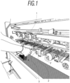
- the wire 1 is manually passed and stretched through a threading die or die holder 2, in order to provide sufficient longitudinal tension to the same wire 1 in its winding on a roller 3 and passing through a wire drawing die or die holder 2' in a single-wire or multi-wire drawing machine.
- the same wire 1 wound on the roller 3 is longitudinally stretched and tensioned in order to achieve a reduction in the diameter of the same wire 1 as a result of this wire drawing process.
- the wire stretching device in a machine or in a wire drawing process of the proposed invention is designed to replace the manual stretching of the wire 1, the passage through a threading die or die holder 2 and the winding on a roller 3 referred to above and represented in an example in figure 1 and which is already known in the state of the art.
- the wire stretching device in a machine or in a wire drawing process of the proposed invention is designed to enable a stretching from a mechanical drive, in order to provide sufficient longitudinal tension in the wire 1 in its winding on the rollers 3, and for this purpose removing any manual operation or stretching on the wire 1 with the drawbacks that this entails.
- the wire stretching device in a machine or in a wire drawing process of the proposed invention is enabled for its installation and/or operation in a single-wire or multi-wire drawing machine, and which are already known in the state of the art.
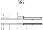
- said wire stretching device in a machine or in a wire drawing process of the proposed invention, comprises a clamp 4 and a die holder with an auxiliary die 5 arranged on a longitudinal bed 6.
- the bed 6 is in turn enabled for its arrangement and attachment to a wire drawing machine of those already known in the state of the art.
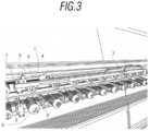
- the die holder with an auxiliary die 5 is attached to the bed 6, and the clamp 4 is linearly movable on the same bed 6 in the direction indicated by the bidirectional arrow in figures 2 and 3 .
- the wire stretching device in a machine or in a wire drawing process of the invention also comprises drive means 7 linked to the clamp 4 and arranged on the bed 6, and enabled for communicating the linear movement to the clamp 4 in the same bed 6.
- the same clamp 4 is enabled for a fastening and attachment therein of one end of a wire 1
- the die holder with an auxiliary die 5 is enabled for a passage and circulation therethrough of the same wire 1 attached by its end to the clamp 4, which will allow the reduction of wire 1 by means of the die to achieve the required wire length 1 to be able to attach it to the following pull roller 3, by means of turns in the same roller 3, the linear movement of the clamp 4 communicated from the drive means 7 thus entailing a stretching and tensioning of the wire 1 that is fastened in the clamp 4 as this wire passes and circulates through the die holder with an auxiliary die 5, as indicated by the arrow in figure 2 .
- the drive means 7 can be of a pneumatic nature, or an electrical drive, for example.
- the wire stretching device in machine or in a wire drawing process of the invention allows the usual and well-known stretching and previous manual actuation of a wire 1 for proceeding to its drawing and represented in an example in the figure 1 to be replaced by stretching but now in a purely mechanical manner, and without requiring any manual stretching or operation on the wire 1 for this purpose and with the consequent advantages that this entails.
- the eminently linear arrangement in the wire stretching device in a single-wire or multi-wire machine or in a wire drawing process of the proposed invention also entails a notable advantage in relation to other machines of the known state of the art, such as in the case of rotary machines already known for this purpose in the state of the art.
Landscapes
- Engineering & Computer Science (AREA)
- Mechanical Engineering (AREA)
- Metal Extraction Processes (AREA)
Priority Applications (1)
| Application Number | Priority Date | Filing Date | Title |
|---|---|---|---|
| EP23382817.7A EP4501481A1 (de) | 2023-08-04 | 2023-08-04 | Drahtziehvorrichtung in einer ein- oder mehrdrahtmaschine oder in einem drahtziehverfahren |
Applications Claiming Priority (1)
| Application Number | Priority Date | Filing Date | Title |
|---|---|---|---|
| EP23382817.7A EP4501481A1 (de) | 2023-08-04 | 2023-08-04 | Drahtziehvorrichtung in einer ein- oder mehrdrahtmaschine oder in einem drahtziehverfahren |
Publications (1)
| Publication Number | Publication Date |
|---|---|
| EP4501481A1 true EP4501481A1 (de) | 2025-02-05 |
Family
ID=88097645
Family Applications (1)
| Application Number | Title | Priority Date | Filing Date |
|---|---|---|---|
| EP23382817.7A Pending EP4501481A1 (de) | 2023-08-04 | 2023-08-04 | Drahtziehvorrichtung in einer ein- oder mehrdrahtmaschine oder in einem drahtziehverfahren |
Country Status (1)
| Country | Link |
|---|---|
| EP (1) | EP4501481A1 (de) |
Citations (6)
| Publication number | Priority date | Publication date | Assignee | Title |
|---|---|---|---|---|
| DE2131273A1 (de) * | 1971-06-24 | 1973-01-11 | Niehoff Kg Maschf | Verfahren und vorrichtung zum anspitzen von stranggutenden, z.b. von drahtenden, und einfuehren des angespitzten drahtendes in einen ziehstein |
| SU1696031A1 (ru) * | 1989-06-08 | 1991-12-07 | Алма-Атинский Завод Тяжелого Машиностроения Им.60-Летия Ссср | Выт гивающий механизм проволоки волочильного стана |
| DE3329459C2 (de) * | 1983-08-16 | 1994-12-08 | Buderus Schleiftechnik | Anordnung zum mehrstufigen Ziehen von Metalldrähten |
| US5855136A (en) * | 1996-08-29 | 1999-01-05 | Mannesmann Aktiengesellschaft | Process and device for threading elongated metal workpieces, especially tubes, into a drawing apparatus |
| EP3815805A1 (de) * | 2019-10-31 | 2021-05-05 | Tecnopress s.r.l. | Vorrichtung zum kontinuierlichen linearen ziehen für eine horizontale automatische kaltschmiedepresse |
| WO2022029469A1 (en) * | 2020-08-05 | 2022-02-10 | Danieli & C. Officine Meccaniche S.P.A. | Drawing bench for drawing machine |
-
2023
- 2023-08-04 EP EP23382817.7A patent/EP4501481A1/de active Pending
Patent Citations (6)
| Publication number | Priority date | Publication date | Assignee | Title |
|---|---|---|---|---|
| DE2131273A1 (de) * | 1971-06-24 | 1973-01-11 | Niehoff Kg Maschf | Verfahren und vorrichtung zum anspitzen von stranggutenden, z.b. von drahtenden, und einfuehren des angespitzten drahtendes in einen ziehstein |
| DE3329459C2 (de) * | 1983-08-16 | 1994-12-08 | Buderus Schleiftechnik | Anordnung zum mehrstufigen Ziehen von Metalldrähten |
| SU1696031A1 (ru) * | 1989-06-08 | 1991-12-07 | Алма-Атинский Завод Тяжелого Машиностроения Им.60-Летия Ссср | Выт гивающий механизм проволоки волочильного стана |
| US5855136A (en) * | 1996-08-29 | 1999-01-05 | Mannesmann Aktiengesellschaft | Process and device for threading elongated metal workpieces, especially tubes, into a drawing apparatus |
| EP3815805A1 (de) * | 2019-10-31 | 2021-05-05 | Tecnopress s.r.l. | Vorrichtung zum kontinuierlichen linearen ziehen für eine horizontale automatische kaltschmiedepresse |
| WO2022029469A1 (en) * | 2020-08-05 | 2022-02-10 | Danieli & C. Officine Meccaniche S.P.A. | Drawing bench for drawing machine |
Similar Documents
| Publication | Publication Date | Title |
|---|---|---|
| EP4501481A1 (de) | Drahtziehvorrichtung in einer ein- oder mehrdrahtmaschine oder in einem drahtziehverfahren | |
| EP3144257B1 (de) | Verfahren zum betreiben einer arbeitsstelle und arbeitsstelle | |
| CN108729047B (zh) | 缝纫机 | |
| US3428096A (en) | Machine for tying coils and packs of iron for instance of rolled iron with wire | |
| GB1049274A (en) | A method and apparatus for straightening rods and wires | |
| KR930009398B1 (ko) | 의복단추생크부의 감침방법 및 장치 | |
| CN117802660A (zh) | 一种分丝整经机筒子张紧装置及方法 | |
| CN212582055U (zh) | 一种双工位合线编织机构 | |
| EP2592179A1 (de) | Klöppel für eine Flechtmaschine und eine mit diesem ausgestattete Flechtmaschine sowie Verfahren zum Aufbringen einer Spannung auf ein Flechtmaterial | |
| US1812506A (en) | Woven wire fabric machine | |
| EP0294978B1 (de) | Drahtversorgungsverfahren und Gerät | |
| US1459623A (en) | Machine for making bale ties | |
| DE296286C (de) | ||
| RU2132278C1 (ru) | Устройство для изготовления покрышек пневматических шин | |
| GB190514797A (en) | Improvements in, and relating to, Machines for Making Wire Fabrics | |
| US2967414A (en) | Method of drawing off chain knitted articles | |
| DE182295C (de) | ||
| DE1227398B (de) | Verfahren und Vorrichtung zur Herstellung von Kurzketten, insbesondere fuer Gewebemuster in der Buntweberei | |
| AT70867B (de) | Selbsttätig wirkende Vorrichtung zur Änderung der Umlaufzahl von Arbeitsmaschinen. | |
| US1610858A (en) | Device for tensioning and binding bands on boxes, bales, and the like | |
| EP3812328B1 (de) | Ringspinnmaschine sowie kopsgreifer | |
| SU147483A1 (ru) | Станок дл обмотки заплетенных тросов | |
| CN209619727U (zh) | 一种剖布机的剖布装置 | |
| US1152379A (en) | Machine for handling tuft-yarns for carpet-looms. | |
| US587520A (en) | Petee k |
Legal Events
| Date | Code | Title | Description |
|---|---|---|---|
| PUAI | Public reference made under article 153(3) epc to a published international application that has entered the european phase |
Free format text: ORIGINAL CODE: 0009012 |
|
| STAA | Information on the status of an ep patent application or granted ep patent |
Free format text: STATUS: THE APPLICATION HAS BEEN PUBLISHED |
|
| AK | Designated contracting states |
Kind code of ref document: A1 Designated state(s): AL AT BE BG CH CY CZ DE DK EE ES FI FR GB GR HR HU IE IS IT LI LT LU LV MC ME MK MT NL NO PL PT RO RS SE SI SK SM TR |
|
| STAA | Information on the status of an ep patent application or granted ep patent |
Free format text: STATUS: THE APPLICATION IS DEEMED TO BE WITHDRAWN |