EP4184629B1 - Elektrodenanordnung - Google Patents
Elektrodenanordnung Download PDFInfo
- Publication number
- EP4184629B1 EP4184629B1 EP21841678.2A EP21841678A EP4184629B1 EP 4184629 B1 EP4184629 B1 EP 4184629B1 EP 21841678 A EP21841678 A EP 21841678A EP 4184629 B1 EP4184629 B1 EP 4184629B1
- Authority
- EP
- European Patent Office
- Prior art keywords
- positive electrode
- active material
- negative electrode
- electrode
- negative
- Prior art date
- Legal status (The legal status is an assumption and is not a legal conclusion. Google has not performed a legal analysis and makes no representation as to the accuracy of the status listed.)
- Active
Links
Images


Classifications
-
- H—ELECTRICITY
- H01—ELECTRIC ELEMENTS
- H01M—PROCESSES OR MEANS, e.g. BATTERIES, FOR THE DIRECT CONVERSION OF CHEMICAL ENERGY INTO ELECTRICAL ENERGY
- H01M10/00—Secondary cells; Manufacture thereof
- H01M10/04—Construction or manufacture in general
- H01M10/0431—Cells with wound or folded electrodes
-
- H—ELECTRICITY
- H01—ELECTRIC ELEMENTS
- H01M—PROCESSES OR MEANS, e.g. BATTERIES, FOR THE DIRECT CONVERSION OF CHEMICAL ENERGY INTO ELECTRICAL ENERGY
- H01M50/00—Constructional details or processes of manufacture of the non-active parts of electrochemical cells other than fuel cells, e.g. hybrid cells
- H01M50/50—Current conducting connections for cells or batteries
- H01M50/531—Electrode connections inside a battery casing
- H01M50/538—Connection of several leads or tabs of wound or folded electrode stacks
-
- H—ELECTRICITY
- H01—ELECTRIC ELEMENTS
- H01M—PROCESSES OR MEANS, e.g. BATTERIES, FOR THE DIRECT CONVERSION OF CHEMICAL ENERGY INTO ELECTRICAL ENERGY
- H01M10/00—Secondary cells; Manufacture thereof
- H01M10/05—Accumulators with non-aqueous electrolyte
- H01M10/058—Construction or manufacture
- H01M10/0587—Construction or manufacture of accumulators having only wound construction elements, i.e. wound positive electrodes, wound negative electrodes and wound separators
-
- Y—GENERAL TAGGING OF NEW TECHNOLOGICAL DEVELOPMENTS; GENERAL TAGGING OF CROSS-SECTIONAL TECHNOLOGIES SPANNING OVER SEVERAL SECTIONS OF THE IPC; TECHNICAL SUBJECTS COVERED BY FORMER USPC CROSS-REFERENCE ART COLLECTIONS [XRACs] AND DIGESTS
- Y02—TECHNOLOGIES OR APPLICATIONS FOR MITIGATION OR ADAPTATION AGAINST CLIMATE CHANGE
- Y02E—REDUCTION OF GREENHOUSE GAS [GHG] EMISSIONS, RELATED TO ENERGY GENERATION, TRANSMISSION OR DISTRIBUTION
- Y02E60/00—Enabling technologies; Technologies with a potential or indirect contribution to GHG emissions mitigation
- Y02E60/10—Energy storage using batteries
-
- Y—GENERAL TAGGING OF NEW TECHNOLOGICAL DEVELOPMENTS; GENERAL TAGGING OF CROSS-SECTIONAL TECHNOLOGIES SPANNING OVER SEVERAL SECTIONS OF THE IPC; TECHNICAL SUBJECTS COVERED BY FORMER USPC CROSS-REFERENCE ART COLLECTIONS [XRACs] AND DIGESTS
- Y02—TECHNOLOGIES OR APPLICATIONS FOR MITIGATION OR ADAPTATION AGAINST CLIMATE CHANGE
- Y02P—CLIMATE CHANGE MITIGATION TECHNOLOGIES IN THE PRODUCTION OR PROCESSING OF GOODS
- Y02P70/00—Climate change mitigation technologies in the production process for final industrial or consumer products
- Y02P70/50—Manufacturing or production processes characterised by the final manufactured product
Definitions
- lithium secondary batteries are generally manufactured by mounting an electrode assembly, in which a positive electrode (cathode), a separator, and a negative electrode (anode) are stacked, in a case.
- a process in which lithium ions are intercalated and deintercalated from lithium metal oxide to the negative electrode, is repeated to charge and discharge the lithium secondary batteries.
- a main object of the present invention for solving the above problem is to provide an electrode assembly, in which a positive electrode capacity on an area in the vicinity of a central hole and a positive electrode capacity in an outer area are different from each other, or a positive electrode capacity on the area in the vicinity of the central hole and a positive electrode capacity in the outer area are different from each other to reduce a deviation in N/P ratio.
- An amount of positive electrode active material applied to the first positive electrode and an amount of positive electrode active material applied to the second positive electrode may be the same.
- the second positive electrode may be manufactured so that at least one of at least one of an amount of positive electrode active material applied to one surface of the positive electrode collector; or a composition ratio based on an atomic ratio or mass ratio of the positive electrode active material is different from that of the positive electrode active material applied to the other surface of the positive electrode collector so that a capacity per unit area on the one surface and a capacity per unit area on the other surface are different from each other.
- the negative electrode tab may have one side welded to the negative electrode non-coating portion of the first negative electrode and the other side welded to the negative electrode non-coating portion of the second negative electrode.
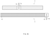
- an electrode assembly of the present invention is an electrode assembly manufactured by winding a separator, the negative electrode 200, a separator, and the positive electrode 100, which are in a stacked state.
- the negative electrode 200 and the positive electrode 100 are sequentially put to manufacture the electrode assembly.
- each of the first positive electrode 10 and the second positive electrode 20 has a structure in which positive electrode non-coating portions 11 and 21, on which the positive electrode active material is not applied to expose the positive electrode collector, are formed on ends thereof, and the positive electrode non-coating portions 11 and 21 of the second positive electrode 20 are bonded to each other through welding or a conductive adhesive.
- composition ratio of the positive electrode active material applied to the positive electrode collector C may vary, and thus, the capacities per unit area of the first positive electrode 10 and the second positive electrode 20 may be different from each other.
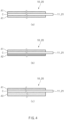
- a negative electrode tab 60 is overlappingly bonded to a point at which the negative electrode non-coating portion 41 of the first negative electrode 40 and the negative electrode non-coating portion 51 of the second negative electrode 50 are bonded to each other.
- the negative electrode tab 60 is bonded so that one side thereof is welded to the negative electrode non-coating portion 41 of the first negative electrode 40, and the other side thereof is welded to the negative electrode non-coating portion 51 of the second negative electrode 50.
- the negative electrode tab 60 may allow the first negative electrode 40 and the second negative electrode 50 to increase in bonding force therebetween.
- each of the first negative electrode 40 and the second negative electrode 50 may have a structure in which a negative active material having the same composition ratio is applied at the same thickness to one side and the other side of the negative electrode collector.
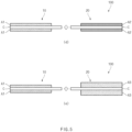
- the positive electrode active materials having the same composition ratio may be applied to both surfaces of the negative electrode collector, but the capacities per unit area may be different from each other by a more amount of positive electrode active material on the other surface than that of the positive electrode active material applied on the one surface.
- the capacities per unit area of the first negative electrode 40 and the second negative electrode 50 may be differently formed in the same manner as in the configuration in which the capacities per unit area of the first positive electrode 10 and the second positive electrode 20 are differently formed by combining the above features.
Landscapes
- Chemical & Material Sciences (AREA)
- Chemical Kinetics & Catalysis (AREA)
- Electrochemistry (AREA)
- General Chemical & Material Sciences (AREA)
- Engineering & Computer Science (AREA)
- Manufacturing & Machinery (AREA)
- Secondary Cells (AREA)
- Battery Electrode And Active Subsutance (AREA)
Claims (14)
- Elektrodenanordnung, in der eine positive Elektrode, ein Separator, eine negative Elektrode in einem gestapelten Zustand gewickelt sind,wobei die positive Elektrode eine erste positive Elektrode und eine zweite positive Elektrode umfasst,jede der ersten positiven Elektrode und der zweiten positiven Elektrode durch Aufbringen eines Positivelektrodenaktivmaterials auf eine Oberfläche eines Positivelektrodenkollektors hergestellt ist, wobei das Positivelektrodenaktivmaterial nicht auf ein Ende aufgebracht ist, um einen Positivelektrodennichtbeschichtungsabschnitt zu bilden, auf dem der Positivelektrodenkollektor freiliegt,die Positivelektrodennichtbeschichtungsabschnitte der ersten positiven Elektrode und der zweiten positiven Elektrode so verbunden sind, dass sie miteinander verbunden sind, undwobei eine Kapazität pro Flächeneinheit der ersten positiven Elektrode und eine Kapazität pro Flächeneinheit der zweiten positiven Elektrode voneinander verschieden sind.
- Elektrodenanordnung nach Anspruch 1, wobei das Positivaktivmaterial, das auf die erste positive Elektrode aufgebracht ist, und das Positivelektrodenaktivmaterial, das auf die zweite positive Elektrode aufgebracht ist, durch Mischen der gleichen Zusammensetzungen hergestellt sind, aber ein Zusammensetzungsverhältnis des Positivelektrodenaktivmaterials, das auf die erste positive Elektrode aufgebracht ist, und ein Zusammensetzungsverhältnis des Positivelektrodenaktivmaterials, das auf die zweite positive Elektrode aufgebracht ist, basierend auf einem Atomverhältnis oder Massenverhältnis unterschiedlich eingestellt sind, so dass die Kapazität pro Flächeneinheit der ersten positiven Elektrode und die Kapazität pro Flächeneinheit der zweiten positiven Elektrode voneinander verschieden sind.
- Elektrodenanordnung nach Anspruch 2, wobei eine Menge an Positivelektrodenaktivmaterial, das auf die erste positive Elektrode aufgebracht ist, und eine Menge an Positivelektrodenaktivmaterial, das auf die zweite positive Elektrode aufgebracht ist, gleich sind.
- Elektrodenanordnung nach Anspruch 1, wobei das Positivaktivmaterial, das auf die erste positive Elektrode aufgebracht ist, und das Positivelektrodenaktivmaterial, das auf die zweite positive Elektrode aufgebracht ist, durch Mischen der gleichen Zusammensetzungen hergestellt sind, aber eine Menge an Positivelektrodenaktivmaterial, das auf die erste positive Elektrode aufgebracht ist, und eine Menge an Positivelektrodenaktivmaterial, das auf die zweite positive Elektrode aufgebracht ist, unterschiedlich eingestellt sind, so dass die Kapazität pro Flächeneinheit der ersten positiven Elektrode und die Kapazität pro Flächeneinheit der zweiten positiven Elektrode voneinander verschieden sind.
- Elektrodenanordnung nach Anspruch 4, wobei die Menge an Positivelektrodenaktivmaterial, das auf die erste positive Elektrode aufgebracht ist, und die Menge an Positivelektrodenaktivmaterial, das auf die zweite positive Elektrode aufgebracht ist, das gleiche Zusammensetzungsverhältnis basierend auf einem Atomverhältnis oder Massenverhältnis aufweisen.
- Elektrodenanordnung nach Anspruch 1, wobei das Positivaktivmaterial, das auf die erste positive Elektrode aufgebracht ist, und das Positivelektrodenaktivmaterial, das auf die zweite positive Elektrode aufgebracht ist, durch Mischen der gleichen Zusammensetzungen hergestellt sind, aber eine Menge an Positivelektrodenaktivmaterial, das auf die erste positive Elektrode aufgebracht ist, und ein Zusammensetzungsverhältnis des Positivelektrodenaktivmaterials, das auf die erste positive Elektrode aufgebracht ist, eingestellt sind, um von einer Menge an Positivelektrodenaktivmaterial, das auf die zweite positive Elektrode aufgebracht ist, und einem Zusammensetzungsverhältnis des Positivelektrodenaktivmaterials, das auf die zweite positive Elektrode aufgebracht ist, verschieden zu sein, so dass die Kapazität pro Flächeneinheit der ersten positiven Elektrode und die Kapazität pro Flächeneinheit der zweiten positiven Elektrode voneinander verschieden sind.
- Elektrodenanordnung nach Anspruch 1, wobei eine Positivelektrodenlasche überlappend mit einem Punkt verbunden ist, an dem der Positivelektrodennichtbeschichtungsabschnitt der ersten positiven Elektrode und der Positivelektrodennichtbeschichtungsabschnitt der zweiten positiven Elektrode miteinander verbunden sind.
- Elektrodenanordnung nach Anspruch 7, wobei die Positivelektrodenlasche eine Seite, die mit dem Positivelektrodennichtbeschichtungsabschnitt der ersten positiven Elektrode verschweißt ist, und die andere Seite, die mit dem Positivelektrodennichtbeschichtungsabschnitt der zweiten positiven Elektrode verschweißt ist, aufweist.
- Elektrodenanordnung nach Anspruch 1, wobei die erste positive Elektrode so hergestellt ist, dass mindestens eines von mindestens einem von einer Menge an Positivelektrodenaktivmaterial, das auf eine Oberfläche des Positivelektrodenkollektors aufgebracht ist; oder einem Zusammensetzungsverhältnis basierend auf einem Atomverhältnis oder Massenverhältnis des Positivelektrodenaktivmaterials von dem des Positivelektrodenaktivmaterials, das auf die andere Oberfläche des Positivelektrodenkollektors aufgebracht ist, verschieden ist, so dass eine Kapazität pro Flächeneinheit auf der einen Oberfläche und eine Kapazität pro Flächeneinheit auf der anderen Oberfläche voneinander verschieden sind.
- Elektrodenanordnung nach Anspruch 1, wobei die zweite positive Elektrode so hergestellt ist, dass mindestens eines von mindestens einem von einer Menge an Positivelektrodenaktivmaterial, das auf eine Oberfläche des Positivelektrodenkollektors aufgebracht ist; oder einem Zusammensetzungsverhältnis basierend auf einem Atomverhältnis oder Massenverhältnis des Positivelektrodenaktivmaterials von dem des Positivelektrodenaktivmaterials, das auf die andere Oberfläche des Positivelektrodenkollektors aufgebracht ist, verschieden ist, so dass eine Kapazität pro Flächeneinheit auf der einen Oberfläche und eine Kapazität pro Flächeneinheit auf der anderen Oberfläche voneinander verschieden sind.
- Elektrodenanordnung, in der eine negative Elektrode, ein Separator, eine positive Elektrode in einem gestapelten Zustand gewickelt sind,wobei die negative Elektrode eine erste negative Elektrode und eine zweite negative Elektrode umfasst,jede der ersten negativen Elektrode und der zweiten negativen Elektrode durch Aufbringen eines Negativelektrodenaktivmaterials auf eine Oberfläche eines Negativelektrodenkollektors hergestellt ist, wobei das Negativelektrodenaktivmaterial nicht auf ein Ende aufgebracht ist, um einen Negativelektrodennichtbeschichtungsabschnitt zu bilden, auf dem der Negativelektrodenkollektor freiliegt,die Negativelektrodennichtbeschichtungsabschnitte der ersten negativen Elektrode und der zweiten negativen Elektrode so verbunden sind, dass sie miteinander verbunden sind, undwobei eine Kapazität pro Flächeneinheit der ersten negativen Elektrode und eine Kapazität pro Flächeneinheit der zweiten negativen Elektrode voneinander verschieden sind.
- Elektrodenanordnung nach Anspruch 11, wobei das Negativaktivmaterial, das auf die erste negative Elektrode aufgebracht ist, und das Negativelektrodenaktivmaterial, das auf die zweite negative Elektrode aufgebracht ist, durch Mischen der gleichen Zusammensetzungen hergestellt sind, aber ein Zusammensetzungsverhältnis des Negativelektrodenaktivmaterials, das auf die erste negative Elektrode aufgebracht ist, und ein Zusammensetzungsverhältnis des Negativelektrodenaktivmaterials, das auf die zweite negative Elektrode aufgebracht ist, basierend auf einem Atomverhältnis oder Massenverhältnis unterschiedlich eingestellt sind.
- Elektrodenanordnung nach Anspruch 11, wobei eine Menge an Negativelektrodenaktivmaterial, das auf die erste negative Elektrode aufgebracht ist, und eine Menge an Negativelektrodenaktivmaterial, das auf die zweite negative Elektrode aufgebracht ist, gleich sind.
- Elektrodenanordnung nach Anspruch 11, wobei das Negativaktivmaterial, das auf die erste negative Elektrode aufgebracht ist, und das Negativelektrodenaktivmaterial, das auf die zweite negative Elektrode aufgebracht ist, durch Mischen der gleichen Zusammensetzungen hergestellt sind, aber eine Menge an Negativelektrodenaktivmaterial, das auf die erste negative Elektrode aufgebracht ist, und eine Menge an Negativelektrodenaktivmaterial, das auf die zweite negative Elektrode aufgebracht ist, unterschiedlich eingestellt sind.
Applications Claiming Priority (3)
| Application Number | Priority Date | Filing Date | Title |
|---|---|---|---|
| KR20200088408 | 2020-07-16 | ||
| KR1020210093046A KR102816048B1 (ko) | 2020-07-16 | 2021-07-15 | 전극조립체 |
| PCT/KR2021/009173 WO2022015101A1 (ko) | 2020-07-16 | 2021-07-16 | 전극조립체 |
Publications (3)
| Publication Number | Publication Date |
|---|---|
| EP4184629A1 EP4184629A1 (de) | 2023-05-24 |
| EP4184629A4 EP4184629A4 (de) | 2024-05-01 |
| EP4184629B1 true EP4184629B1 (de) | 2025-04-09 |
Family
ID=79554852
Family Applications (1)
| Application Number | Title | Priority Date | Filing Date |
|---|---|---|---|
| EP21841678.2A Active EP4184629B1 (de) | 2020-07-16 | 2021-07-16 | Elektrodenanordnung |
Country Status (6)
| Country | Link |
|---|---|
| US (1) | US12476335B2 (de) |
| EP (1) | EP4184629B1 (de) |
| CN (1) | CN115803924A (de) |
| ES (1) | ES3032436T3 (de) |
| HU (1) | HUE071309T2 (de) |
| WO (1) | WO2022015101A1 (de) |
Family Cites Families (16)
| Publication number | Priority date | Publication date | Assignee | Title |
|---|---|---|---|---|
| JP2001236983A (ja) | 2000-02-25 | 2001-08-31 | Sanoh Industrial Co Ltd | 電池用捲回電極 |
| KR100496294B1 (ko) * | 2002-12-28 | 2005-06-17 | 삼성에스디아이 주식회사 | 전극조립체와 이를 이용한 이차전지 |
| KR100515833B1 (ko) * | 2003-05-26 | 2005-09-21 | 삼성에스디아이 주식회사 | 젤리-롤형의 전극조립체와 이를 채용한 이차전지 |
| KR20080037867A (ko) * | 2006-10-27 | 2008-05-02 | 삼성에스디아이 주식회사 | 전극조립체와 이를 이용한 리튬 이차전지 및 리튬이차전지의 제조방법 |
| KR100963981B1 (ko) | 2007-03-26 | 2010-06-15 | 주식회사 엘지화학 | 로딩량이 다른 활물질층을 포함하고 있는 젤리-롤 |
| JP2008262777A (ja) | 2007-04-11 | 2008-10-30 | Sony Corp | 二次電池 |
| US20110223456A1 (en) | 2009-10-28 | 2011-09-15 | Junichi Sugaya | Electrode, secondary battery, and fabrication method of secondary battery |
| JP2011204660A (ja) | 2010-03-04 | 2011-10-13 | Sanyo Electric Co Ltd | リチウム二次電池 |
| KR20120060537A (ko) | 2010-12-02 | 2012-06-12 | 현대자동차주식회사 | 젤리-롤형 전극조립체 구조 |
| WO2013038946A1 (ja) | 2011-09-14 | 2013-03-21 | 株式会社Gsユアサ | 円筒形電池 |
| KR101637890B1 (ko) * | 2013-05-30 | 2016-07-08 | 주식회사 엘지화학 | 2개 이상의 음극 탭들을 포함하는 이차전지 |
| JP2015088272A (ja) * | 2013-10-29 | 2015-05-07 | トヨタ自動車株式会社 | 非水電解質二次電池、およびその製造方法 |
| KR101639209B1 (ko) | 2013-10-30 | 2016-07-13 | 주식회사 엘지화학 | 개선된 구조의 젤리-롤 형 전극 조립체 및 이를 포함하는 이차 전지 |
| KR102502194B1 (ko) * | 2015-10-27 | 2023-02-20 | 삼성에스디아이 주식회사 | 전극 탭을 갖는 이차 전지 및 이차 전지의 제조 방법 |
| KR102239364B1 (ko) * | 2017-06-27 | 2021-04-09 | 주식회사 엘지화학 | 원통형 젤리롤을 포함하는 리튬 이차전지 |
| KR102557413B1 (ko) | 2018-04-25 | 2023-07-18 | 주식회사 엘지에너지솔루션 | 리튬 금속 전극의 제조 방법 |
-
2021
- 2021-07-16 US US18/014,689 patent/US12476335B2/en active Active
- 2021-07-16 ES ES21841678T patent/ES3032436T3/es active Active
- 2021-07-16 WO PCT/KR2021/009173 patent/WO2022015101A1/ko not_active Ceased
- 2021-07-16 HU HUE21841678A patent/HUE071309T2/hu unknown
- 2021-07-16 CN CN202180045163.XA patent/CN115803924A/zh active Pending
- 2021-07-16 EP EP21841678.2A patent/EP4184629B1/de active Active
Also Published As
| Publication number | Publication date |
|---|---|
| EP4184629A1 (de) | 2023-05-24 |
| HUE071309T2 (hu) | 2025-08-28 |
| WO2022015101A1 (ko) | 2022-01-20 |
| ES3032436T3 (en) | 2025-07-18 |
| US20230275329A1 (en) | 2023-08-31 |
| US12476335B2 (en) | 2025-11-18 |
| CN115803924A (zh) | 2023-03-14 |
| EP4184629A4 (de) | 2024-05-01 |
Similar Documents
| Publication | Publication Date | Title |
|---|---|---|
| US20250385292A1 (en) | Secondary Battery and Method for Manufacturing the Same | |
| JP7206562B2 (ja) | 二次電池 | |
| EP4270565A1 (de) | Elektrodenanordnung und sekundärbatterie damit | |
| KR100731452B1 (ko) | 원통형 전지의 극판 권취장치 및 권취방법 | |
| US20100319187A1 (en) | Manufacturing Method of Stacked Electrodes By Winding Type Electrode Stacking and Stacked Electrode Thereby | |
| CN113767504B (zh) | 电极组件及其制造方法 | |
| EP4343954A1 (de) | Elektrodenlasche und verfahren zum schneiden der elektrodenlasche | |
| EP4184629B1 (de) | Elektrodenanordnung | |
| EP3780237A1 (de) | Einheitszelle und herstellungsverfahren dafür | |
| EP3598555B1 (de) | Elektrode, elektrodenanordnung und verfahren zu deren herstellung | |
| KR102816048B1 (ko) | 전극조립체 | |
| JPH0574496A (ja) | 二次電池 | |
| US12300777B2 (en) | Electrode assembly and method for manufacturing same | |
| KR20240056427A (ko) | 전극 조립체 및 이를 포함하는 전기화학소자 | |
| KR20210017086A (ko) | 전극조립체 및 그 제조방법 | |
| EP4164028B1 (de) | Elektrodenanordnung und sekundärbatterie damit | |
| EP4589715A1 (de) | Elektrodenanordnung | |
| EP4589700A1 (de) | Elektrodenanordnung | |
| KR102837704B1 (ko) | 전극 조립체 및 이를 포함하는 전기화학소자 | |
| KR102340101B1 (ko) | 이차 전지 및 이의 제조방법 | |
| KR20240056431A (ko) | 전극 조립체 및 이를 포함하는 전기화학소자 | |
| JP2025520613A (ja) | 電極アセンブリ及びこれを含む電気化学素子 |
Legal Events
| Date | Code | Title | Description |
|---|---|---|---|
| STAA | Information on the status of an ep patent application or granted ep patent |
Free format text: STATUS: THE INTERNATIONAL PUBLICATION HAS BEEN MADE |
|
| PUAI | Public reference made under article 153(3) epc to a published international application that has entered the european phase |
Free format text: ORIGINAL CODE: 0009012 |
|
| STAA | Information on the status of an ep patent application or granted ep patent |
Free format text: STATUS: REQUEST FOR EXAMINATION WAS MADE |
|
| 17P | Request for examination filed |
Effective date: 20221222 |
|
| AK | Designated contracting states |
Kind code of ref document: A1 Designated state(s): AL AT BE BG CH CY CZ DE DK EE ES FI FR GB GR HR HU IE IS IT LI LT LU LV MC MK MT NL NO PL PT RO RS SE SI SK SM TR |
|
| DAV | Request for validation of the european patent (deleted) | ||
| DAX | Request for extension of the european patent (deleted) | ||
| REG | Reference to a national code |
Ref country code: DE Ref legal event code: R079 Free format text: PREVIOUS MAIN CLASS: H01M0010040000 Ipc: H01M0004139000 Ref country code: DE Ref legal event code: R079 Ref document number: 602021029038 Country of ref document: DE Free format text: PREVIOUS MAIN CLASS: H01M0010040000 Ipc: H01M0004139000 |
|
| A4 | Supplementary search report drawn up and despatched |
Effective date: 20240403 |
|
| RIC1 | Information provided on ipc code assigned before grant |
Ipc: H01M 10/0587 20100101ALI20240326BHEP Ipc: H01M 50/536 20210101ALI20240326BHEP Ipc: H01M 10/04 20060101ALI20240326BHEP Ipc: H01M 4/139 20100101AFI20240326BHEP |
|
| GRAP | Despatch of communication of intention to grant a patent |
Free format text: ORIGINAL CODE: EPIDOSNIGR1 |
|
| STAA | Information on the status of an ep patent application or granted ep patent |
Free format text: STATUS: GRANT OF PATENT IS INTENDED |
|
| GRAS | Grant fee paid |
Free format text: ORIGINAL CODE: EPIDOSNIGR3 |
|
| INTG | Intention to grant announced |
Effective date: 20250131 |
|
| GRAA | (expected) grant |
Free format text: ORIGINAL CODE: 0009210 |
|
| STAA | Information on the status of an ep patent application or granted ep patent |
Free format text: STATUS: THE PATENT HAS BEEN GRANTED |
|
| AK | Designated contracting states |
Kind code of ref document: B1 Designated state(s): AL AT BE BG CH CY CZ DE DK EE ES FI FR GB GR HR HU IE IS IT LI LT LU LV MC MK MT NL NO PL PT RO RS SE SI SK SM TR |
|
| P01 | Opt-out of the competence of the unified patent court (upc) registered |
Free format text: CASE NUMBER: APP_10245/2025 Effective date: 20250228 |
|
| REG | Reference to a national code |
Ref country code: GB Ref legal event code: FG4D |
|
| REG | Reference to a national code |
Ref country code: CH Ref legal event code: EP |
|
| REG | Reference to a national code |
Ref country code: DE Ref legal event code: R096 Ref document number: 602021029038 Country of ref document: DE |
|
| REG | Reference to a national code |
Ref country code: IE Ref legal event code: FG4D |
|
| PGFP | Annual fee paid to national office [announced via postgrant information from national office to epo] |
Ref country code: GB Payment date: 20250624 Year of fee payment: 5 |
|
| PGFP | Annual fee paid to national office [announced via postgrant information from national office to epo] |
Ref country code: BE Payment date: 20250623 Year of fee payment: 5 |
|
| PGFP | Annual fee paid to national office [announced via postgrant information from national office to epo] |
Ref country code: FR Payment date: 20250624 Year of fee payment: 5 |
|
| REG | Reference to a national code |
Ref country code: ES Ref legal event code: FG2A Ref document number: 3032436 Country of ref document: ES Kind code of ref document: T3 Effective date: 20250718 |
|
| PGFP | Annual fee paid to national office [announced via postgrant information from national office to epo] |
Ref country code: HU Payment date: 20250721 Year of fee payment: 5 |
|
| REG | Reference to a national code |
Ref country code: NL Ref legal event code: MP Effective date: 20250409 |
|
| REG | Reference to a national code |
Ref country code: HU Ref legal event code: AG4A Ref document number: E071309 Country of ref document: HU |
|
| PG25 | Lapsed in a contracting state [announced via postgrant information from national office to epo] |
Ref country code: NL Free format text: LAPSE BECAUSE OF FAILURE TO SUBMIT A TRANSLATION OF THE DESCRIPTION OR TO PAY THE FEE WITHIN THE PRESCRIBED TIME-LIMIT Effective date: 20250409 |
|
| REG | Reference to a national code |
Ref country code: AT Ref legal event code: MK05 Ref document number: 1784390 Country of ref document: AT Kind code of ref document: T Effective date: 20250409 |
|
| PG25 | Lapsed in a contracting state [announced via postgrant information from national office to epo] |
Ref country code: FI Free format text: LAPSE BECAUSE OF FAILURE TO SUBMIT A TRANSLATION OF THE DESCRIPTION OR TO PAY THE FEE WITHIN THE PRESCRIBED TIME-LIMIT Effective date: 20250409 Ref country code: PT Free format text: LAPSE BECAUSE OF FAILURE TO SUBMIT A TRANSLATION OF THE DESCRIPTION OR TO PAY THE FEE WITHIN THE PRESCRIBED TIME-LIMIT Effective date: 20250811 |
|
| PGFP | Annual fee paid to national office [announced via postgrant information from national office to epo] |
Ref country code: ES Payment date: 20250822 Year of fee payment: 5 |
|
| PGFP | Annual fee paid to national office [announced via postgrant information from national office to epo] |
Ref country code: DE Payment date: 20250624 Year of fee payment: 5 |
|
| REG | Reference to a national code |
Ref country code: LT Ref legal event code: MG9D |
|
| PG25 | Lapsed in a contracting state [announced via postgrant information from national office to epo] |
Ref country code: NO Free format text: LAPSE BECAUSE OF FAILURE TO SUBMIT A TRANSLATION OF THE DESCRIPTION OR TO PAY THE FEE WITHIN THE PRESCRIBED TIME-LIMIT Effective date: 20250709 Ref country code: GR Free format text: LAPSE BECAUSE OF FAILURE TO SUBMIT A TRANSLATION OF THE DESCRIPTION OR TO PAY THE FEE WITHIN THE PRESCRIBED TIME-LIMIT Effective date: 20250710 |
|
| PG25 | Lapsed in a contracting state [announced via postgrant information from national office to epo] |
Ref country code: PL Free format text: LAPSE BECAUSE OF FAILURE TO SUBMIT A TRANSLATION OF THE DESCRIPTION OR TO PAY THE FEE WITHIN THE PRESCRIBED TIME-LIMIT Effective date: 20250409 |
|
| PG25 | Lapsed in a contracting state [announced via postgrant information from national office to epo] |
Ref country code: BG Free format text: LAPSE BECAUSE OF FAILURE TO SUBMIT A TRANSLATION OF THE DESCRIPTION OR TO PAY THE FEE WITHIN THE PRESCRIBED TIME-LIMIT Effective date: 20250409 |
|
| PG25 | Lapsed in a contracting state [announced via postgrant information from national office to epo] |
Ref country code: HR Free format text: LAPSE BECAUSE OF FAILURE TO SUBMIT A TRANSLATION OF THE DESCRIPTION OR TO PAY THE FEE WITHIN THE PRESCRIBED TIME-LIMIT Effective date: 20250409 |
|
| PG25 | Lapsed in a contracting state [announced via postgrant information from national office to epo] |
Ref country code: AT Free format text: LAPSE BECAUSE OF FAILURE TO SUBMIT A TRANSLATION OF THE DESCRIPTION OR TO PAY THE FEE WITHIN THE PRESCRIBED TIME-LIMIT Effective date: 20250409 |
|
| PG25 | Lapsed in a contracting state [announced via postgrant information from national office to epo] |
Ref country code: RS Free format text: LAPSE BECAUSE OF FAILURE TO SUBMIT A TRANSLATION OF THE DESCRIPTION OR TO PAY THE FEE WITHIN THE PRESCRIBED TIME-LIMIT Effective date: 20250709 |
|
| PG25 | Lapsed in a contracting state [announced via postgrant information from national office to epo] |
Ref country code: IS Free format text: LAPSE BECAUSE OF FAILURE TO SUBMIT A TRANSLATION OF THE DESCRIPTION OR TO PAY THE FEE WITHIN THE PRESCRIBED TIME-LIMIT Effective date: 20250809 |
|
| PG25 | Lapsed in a contracting state [announced via postgrant information from national office to epo] |
Ref country code: LV Free format text: LAPSE BECAUSE OF FAILURE TO SUBMIT A TRANSLATION OF THE DESCRIPTION OR TO PAY THE FEE WITHIN THE PRESCRIBED TIME-LIMIT Effective date: 20250409 |
|
| PG25 | Lapsed in a contracting state [announced via postgrant information from national office to epo] |
Ref country code: SM Free format text: LAPSE BECAUSE OF FAILURE TO SUBMIT A TRANSLATION OF THE DESCRIPTION OR TO PAY THE FEE WITHIN THE PRESCRIBED TIME-LIMIT Effective date: 20250409 Ref country code: DK Free format text: LAPSE BECAUSE OF FAILURE TO SUBMIT A TRANSLATION OF THE DESCRIPTION OR TO PAY THE FEE WITHIN THE PRESCRIBED TIME-LIMIT Effective date: 20250409 |
|
| PG25 | Lapsed in a contracting state [announced via postgrant information from national office to epo] |
Ref country code: CZ Free format text: LAPSE BECAUSE OF FAILURE TO SUBMIT A TRANSLATION OF THE DESCRIPTION OR TO PAY THE FEE WITHIN THE PRESCRIBED TIME-LIMIT Effective date: 20250409 |
|
| PG25 | Lapsed in a contracting state [announced via postgrant information from national office to epo] |
Ref country code: EE Free format text: LAPSE BECAUSE OF FAILURE TO SUBMIT A TRANSLATION OF THE DESCRIPTION OR TO PAY THE FEE WITHIN THE PRESCRIBED TIME-LIMIT Effective date: 20250409 |
|
| PG25 | Lapsed in a contracting state [announced via postgrant information from national office to epo] |
Ref country code: SK Free format text: LAPSE BECAUSE OF FAILURE TO SUBMIT A TRANSLATION OF THE DESCRIPTION OR TO PAY THE FEE WITHIN THE PRESCRIBED TIME-LIMIT Effective date: 20250409 |
|
| PG25 | Lapsed in a contracting state [announced via postgrant information from national office to epo] |
Ref country code: IT Free format text: LAPSE BECAUSE OF FAILURE TO SUBMIT A TRANSLATION OF THE DESCRIPTION OR TO PAY THE FEE WITHIN THE PRESCRIBED TIME-LIMIT Effective date: 20250409 |
|
| PLBE | No opposition filed within time limit |
Free format text: ORIGINAL CODE: 0009261 |
|
| STAA | Information on the status of an ep patent application or granted ep patent |
Free format text: STATUS: NO OPPOSITION FILED WITHIN TIME LIMIT |