EP4180169B1 - Stiftwellendemontage- und -montagevorrichtung - Google Patents
Stiftwellendemontage- und -montagevorrichtung Download PDFInfo
- Publication number
- EP4180169B1 EP4180169B1 EP22772397.0A EP22772397A EP4180169B1 EP 4180169 B1 EP4180169 B1 EP 4180169B1 EP 22772397 A EP22772397 A EP 22772397A EP 4180169 B1 EP4180169 B1 EP 4180169B1
- Authority
- EP
- European Patent Office
- Prior art keywords
- pin shaft
- oil cylinder
- frame body
- connecting seat
- hole
- Prior art date
- Legal status (The legal status is an assumption and is not a legal conclusion. Google has not performed a legal analysis and makes no representation as to the accuracy of the status listed.)
- Active
Links
Images


Classifications
-
- E—FIXED CONSTRUCTIONS
- E02—HYDRAULIC ENGINEERING; FOUNDATIONS; SOIL SHIFTING
- E02F—DREDGING; SOIL-SHIFTING
- E02F9/00—Component parts of dredgers or soil-shifting machines, not restricted to one of the kinds covered by groups E02F3/00 - E02F7/00
- E02F9/006—Pivot joint assemblies
-
- E—FIXED CONSTRUCTIONS
- E02—HYDRAULIC ENGINEERING; FOUNDATIONS; SOIL SHIFTING
- E02F—DREDGING; SOIL-SHIFTING
- E02F9/00—Component parts of dredgers or soil-shifting machines, not restricted to one of the kinds covered by groups E02F3/00 - E02F7/00
- E02F9/28—Small metalwork for digging elements, e.g. teeth scraper bits
- E02F9/2891—Tools for assembling or disassembling
-
- B—PERFORMING OPERATIONS; TRANSPORTING
- B23—MACHINE TOOLS; METAL-WORKING NOT OTHERWISE PROVIDED FOR
- B23P—METAL-WORKING NOT OTHERWISE PROVIDED FOR; COMBINED OPERATIONS; UNIVERSAL MACHINE TOOLS
- B23P19/00—Machines for simply fitting together or separating metal parts or objects, or metal and non-metal parts, whether or not involving some deformation; Tools or devices therefor so far as not provided for in other classes
- B23P19/02—Machines for simply fitting together or separating metal parts or objects, or metal and non-metal parts, whether or not involving some deformation; Tools or devices therefor so far as not provided for in other classes for connecting objects by press fit or for detaching same
- B23P19/027—Machines for simply fitting together or separating metal parts or objects, or metal and non-metal parts, whether or not involving some deformation; Tools or devices therefor so far as not provided for in other classes for connecting objects by press fit or for detaching same using hydraulic or pneumatic means
-
- E—FIXED CONSTRUCTIONS
- E02—HYDRAULIC ENGINEERING; FOUNDATIONS; SOIL SHIFTING
- E02F—DREDGING; SOIL-SHIFTING
- E02F9/00—Component parts of dredgers or soil-shifting machines, not restricted to one of the kinds covered by groups E02F3/00 - E02F7/00
- E02F9/20—Drives; Control devices
- E02F9/22—Hydraulic or pneumatic drives
- E02F9/2264—Arrangements or adaptations of elements for hydraulic drives
- E02F9/2271—Actuators and supports therefor and protection therefor
-
- F—MECHANICAL ENGINEERING; LIGHTING; HEATING; WEAPONS; BLASTING
- F15—FLUID-PRESSURE ACTUATORS; HYDRAULICS OR PNEUMATICS IN GENERAL
- F15B—SYSTEMS ACTING BY MEANS OF FLUIDS IN GENERAL; FLUID-PRESSURE ACTUATORS, e.g. SERVOMOTORS; DETAILS OF FLUID-PRESSURE SYSTEMS, NOT OTHERWISE PROVIDED FOR
- F15B15/00—Fluid-actuated devices for displacing a member from one position to another; Gearing associated therewith
- F15B15/08—Characterised by the construction of the motor unit
- F15B15/14—Characterised by the construction of the motor unit of the straight-cylinder type
- F15B15/1423—Component parts; Constructional details
- F15B15/1428—Cylinders
-
- F—MECHANICAL ENGINEERING; LIGHTING; HEATING; WEAPONS; BLASTING
- F15—FLUID-PRESSURE ACTUATORS; HYDRAULICS OR PNEUMATICS IN GENERAL
- F15B—SYSTEMS ACTING BY MEANS OF FLUIDS IN GENERAL; FLUID-PRESSURE ACTUATORS, e.g. SERVOMOTORS; DETAILS OF FLUID-PRESSURE SYSTEMS, NOT OTHERWISE PROVIDED FOR
- F15B15/00—Fluid-actuated devices for displacing a member from one position to another; Gearing associated therewith
- F15B15/08—Characterised by the construction of the motor unit
- F15B15/14—Characterised by the construction of the motor unit of the straight-cylinder type
- F15B15/1423—Component parts; Constructional details
- F15B15/1457—Piston rods
-
- F—MECHANICAL ENGINEERING; LIGHTING; HEATING; WEAPONS; BLASTING
- F16—ENGINEERING ELEMENTS AND UNITS; GENERAL MEASURES FOR PRODUCING AND MAINTAINING EFFECTIVE FUNCTIONING OF MACHINES OR INSTALLATIONS; THERMAL INSULATION IN GENERAL
- F16C—SHAFTS; FLEXIBLE SHAFTS; ELEMENTS OR CRANKSHAFT MECHANISMS; ROTARY BODIES OTHER THAN GEARING ELEMENTS; BEARINGS
- F16C11/00—Pivots; Pivotal connections
- F16C11/04—Pivotal connections
- F16C11/045—Pivotal connections with at least a pair of arms pivoting relatively to at least one other arm, all arms being mounted on one pin
-
- F—MECHANICAL ENGINEERING; LIGHTING; HEATING; WEAPONS; BLASTING
- F16—ENGINEERING ELEMENTS AND UNITS; GENERAL MEASURES FOR PRODUCING AND MAINTAINING EFFECTIVE FUNCTIONING OF MACHINES OR INSTALLATIONS; THERMAL INSULATION IN GENERAL
- F16C—SHAFTS; FLEXIBLE SHAFTS; ELEMENTS OR CRANKSHAFT MECHANISMS; ROTARY BODIES OTHER THAN GEARING ELEMENTS; BEARINGS
- F16C3/00—Shafts; Axles; Cranks; Eccentrics
- F16C3/02—Shafts; Axles
- F16C3/03—Shafts; Axles telescopic
Definitions
- the present application relates to the technical field of work machine, and in particular, to a pin shaft dismounting and mounting device, a frame body connecting structure and work machine.
- a frame of work machine is generally provided with a pin shaft.
- a gantry of a rotary drilling rig is connected to the frame through the pin shaft, both the frame and the gantry of the rotary drilling rig are provided with a pair of connecting seats, which is disposed at intervals corresponding to each other.
- Each connecting seat includes a pair of connecting plates disposed opposite at intervals and each connecting plate on the gantry and the frame is provided with pin shaft holes correspondingly.
- the connecting plates on the gantry and the frame are first staggered, pin shaft holes on the gantry and the frame are aligned and the pin shaft is mounted into a corresponding pin shaft hole.
- a piston rod of a cylinder is used as the pin shaft.
- the piston rod of the cylinder may be controlled to be stretched and mounted into the corresponding pin shaft hole when being mounted while the piston rod of the cylinder may be controlled to be retracted and withdrawn from the pin shaft hole when being dismounted.
- the piston rod may be worn or deformed after being used for a long time.
- WO2020241349A1 discloses a device according to the preamble of claim 1.
- a first pinhole is formed in a first member (1) in a section facing a second member (3).
- a second pinhole is formed in the second member (3) in a section facing the first member (1).
- a connecting pin (51L) is inserted into the first pinhole and the second pinhole from the side of the machine center.
- a coming-off prevention mechanism 6 includes a coming-off prevention lever (61). The coming-off prevention lever 61 can abut the inner end surface 510L of the connecting pin (51L).
- the coming-off prevention lever 61 is supported by the second member (3) to be able to move between an abutting position of abutting the inner end surface (S10L) of the coupling pin (51L) and a non-abutting position of not abutting the inner end surface 510L.
- JP2013253400A discloses that a hydraulic power unit mounting/removing device which is constructed to reduce time and labor required for mounting/removing a hydraulic power unit on/from a revolving frame.
- first brackets 11 having pin holes 11a are provided protruded to the outside.
- second brackets 18, 19 having pin holes 18a, 19a opposed to the pin holes 11 a of the first brackets 11 are provided.
- connection pins 20 and hydraulic cylinders 21 are mounted which are removably inserted into the pin holes 11a, 19a of the first brackets 11 and the second brackets 19 and which drive the connection pins 20, respectively.
- the present invention provides a pin shaft dismounting and mounting device as per claim 1, which can conveniently disassemble and assemble a pin shaft and solve the problems of wear and deformation of a piston rod.
- the present application further provides a frame body connecting structure and work machine.
- the frame body connecting structure includes a first frame body, a second frame body, and the above-mentioned pin shaft dismounting and mounting device.
- Each of the first frame body and the second frame body is provided with a connecting seat, each connecting seat is provided with a pin shaft, the second frame body is connected with the first frame body through a pin shaft, and the pin shaft is provided with a through hole; the pin shaft dismounting and mounting device is connected with the first frame body or the second frame body and the telescopic rod corresponds to the pin shaft.
- the work machine according to the present application includes the above-mentioned frame body connecting structure.
- the pin shaft may be dismounted and mounted conveniently and the problems of wear and deformation of the piston rod are solved.
- the beneficial effects of the frame body connecting structure and the work machine is generally similar to those of the above-mentioned pin shaft dismounting and mounting device, and will not be repeated here.
- 11 first connecting seat; 12: second connecting seat; 13: pin shaft hole; 14: oil cylinder support base; 15: gantry; 16: frame body; 17: pin shaft; 18: connecting assembly; 19: double-ended oil cylinder; 20: telescopic rod; 21: threaded hole; 22: reversing valve; 23: through hole; 24: annular groove; 25: pull rod; 26: external thread; 27: end cap structure; 28: head-screwing structure; 29: first oil cylinder; 30: second oil cylinder; 31: first clamping body; 32: second clamping body; 33: guide post; 34: chute; 35: guide groove.
- a pin shaft dismounting and mounting device, a frame body connecting structure and work machine according to the embodiments of the present application are described below with reference to FIGS. 1 to 17 .
- the pin shaft dismounting and mounting device includes a linear drive mechanism and a pull rod 25.
- the pin shaft dismounting and mounting device is configured for dismounting and mounting the pin shaft 17 on the connecting seat.
- Each connecting seat is provided with a pin shaft hole 13.
- the connecting seat may be a connecting seat on the frame body 16.
- the frame body 16 is provided with a connecting seat.
- the gantry 15 of the rotary drilling rig is connected to the connecting seat on the frame body 16 through the pin shaft 17.
- the connecting seat can also be a pin connecting seat of other devices, for example, a pin connecting seat on a hoisting machine.
- the pin shaft 17 is mounted inside the pin shaft hole 13 of the connecting seat.
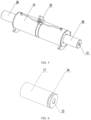
- the pin shaft 17 is provided with a through hole 23 along its axial direction.
- the through hole 23 may be a central hole of the pin shaft 17, specifically a circular hole.
- the linear drive mechanism is disposed on one side of the connecting seat.
- the linear drive mechanism includes a telescopic rod 20 corresponding to the pin shaft hole 13, and having a diameter smaller than a diameter of the pin shaft hole 13 and larger than a diameter of the through hole 23.
- the linear drive mechanism may be an oil cylinder, an air cylinder, a linear motor, etc., and the telescopic rod 20 of the linear drive mechanism can perform telescopic movement along its axial direction.
- the diameter of the telescopic rod 20 is smaller than the diameter of the pin shaft hole 13, and thus the telescopic rod 20 can perform telescopic movement in the pin shaft hole 13, while the diameter of the telescopic rod 20 is larger than the diameter of the through hole 23, and thus the telescopic rod 20 can abut against the end portion of the pin shaft 17 to drive the pin shafts 17 to move.
- the outer diameter of the pull rod 25 is smaller than the inner diameter of the through hole 23 and the pull rod 25 can stretch into or out of the through hole 23.
- a first end of the pull rod 25 is provided with an end cap structure 27 having a radial length greater than the inner diameter of the through hole 23 and a connecting structure is disposed between the second end of the pull rod 25 and the end portion of each telescopic rod 20.
- the length of the main body of the pull rod 25 needs to be greater than the length of the pin shaft 17 and the second end of the pull rod 25 can stretch from an end where the through hole 23 of the pin shaft 17 is located and stretch out from another end of the pin shaft 17.
- the pin shaft 17 and the linear drive mechanism are located on opposite sides of the pin shaft hole 13 respectively.
- the pin shaft is 17 firstly aligned with the pin shaft hole 13, and the second end of the pull rod 25 passes into the through hole 23 of the pin shaft 17 and is connected to the telescopic rod 20 of the linear drive mechanism through the connecting structure after passing through the through hole 23.
- the first end of the pull rod 25 is stuck outside the through hole 23 since the first end of the pull rod 25 is provided with an end cap structure 27, and the radial length of the end cap structure 27 is greater than the inner diameter of the through hole 23.
- the telescopic rod 20 of the linear drive mechanism is controlled to be retracted, and the pin shaft 17 is pulled into the pin shaft hole 13 through the telescopic rod 20 and thus the mounting of the pin shaft 17 is completed.
- the pin shaft 17 needs to be dismounted, and the pin shaft 17 may be pushed out from the pin shaft hole 13 by controlling the telescopic rod 20 of the linear drive mechanism to stretch out.
- the pin shaft 17 may be dismounted and mounted conveniently and the problems of wear and deformation of the piston rod caused by directly adopting the piston rod as the pin shaft 17 are solved.
- the connecting seat includes a first connecting seat 11 and a second connecting seat 12, the first connecting seat 11 may include a pair of lugs disposed at intervals and provided with corresponding pin shaft holes 13.
- the second connecting seat 12 may include a pair of lugs disposed at intervals and provided with corresponding pin shaft holes 13.
- the first connecting seat 11 and the second connecting seat 12 may also have other structures.
- the first connecting seat 11 and the second connecting seat 12 are disposed at intervals, and the linear driving mechanism is disposed between the first connecting seat 11 and the second connecting seat 12.
- a mounting seat for mounting the linear drive mechanism may be disposed on a corresponding surface of the first connecting seat 11 or the second connecting seat 12 and the linear drive mechanism may be connected to the mounting seat through bolts.
- the linear drive mechanism includes a pair of telescopic rods 20, and the pair of telescopic rods 20 correspond to the pin shaft holes 13 of the first connecting seat 11 and the second connecting seat 12 respectively.
- the telescopic rod 20 corresponding to the first connecting seat 11 of the linear drive mechanism is configured to disassemble and assemble the pin shaft 17 of the first connecting seat 11
- the telescopic rod 20 corresponding to the second connecting seat 12 of the linear driving mechanism is configured to disassemble and assemble the pin shaft 17 of the second connecting seat 12.
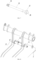
- the linear drive mechanism disposed between the first connecting seat 11 and the second connecting seat 12 is configured as a double-ended oil cylinder 19.
- Two telescopic rods 20 of the double-ended oil cylinder 19 are driven by a hydraulic system to perform telescopic movement, and the disassembly and assembly of the pin shafts 17 at both ends of the double-ended oil cylinder 19 is completed.
- the extending or retraction of the telescopic rods 20 of the double-ended oil cylinder 19 is driven by hydraulic pressure and controlled by a reversing valve 22.
- the double-ended oil cylinder 19 may be single-stage or multi-stage.
- the double-ended oil cylinder 19 can also be replaced with an air cylinder or a linear motor according to different application occasions. When the linear motor is used, a switch is used for control.
- a manual reversing valve may be used to uniformly control the extending or retraction of the two telescopic rods 20 of the double-ended oil cylinder 19.
- the two telescopic rods 20 may be non-synchronous due to uneven resistance and the two telescopic rods 20 can be fully stretched or fully retracted finally.
- Two reversing valves 22 may be used to individually control the two telescopic rods 20 if the independent movement of the two telescopic rods 20 is required.
- an oil cylinder support base 14 may be disposed on corresponding surfaces of the first connecting seat 11 and the second connecting seat 12, a bolt hole is disposed on the oil cylinder support base 14, and both ends of a barrel of the double-ended oil cylinder 19 are respectively connected to the oil cylinder support base 14 by bolts.
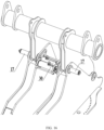
- a first step referring to FIG. 8 , after the connecting assembly 18 between the end portion of the pin shaft 17 and the connecting seat is removed, the double-ended oil cylinder 19 is operated to stretch the two telescopic rods 20, and the pin shaft 17 is then ejected by the telescopic rod 20, the pin shaft 17 remains in the pin shaft hole 13 of an outer lug plate of the frame body 16 (the pin shaft 17 is in a disengaged state).
- the telescopic rod 20 remains inside the pin shaft hole 13 and the surface of the telescopic rod 20 will not be worn by the pin shaft hole 13 since the outer diameter of the telescopic rod 20 is smaller than the inner diameter of the pin shaft hole 13.
- the double-ended oil cylinder 19 is operated to retract the two telescopic rods 20 and the pin shaft 17 remains in the pin shaft hole 13 of an outer lug plate of the frame body 16.
- the gantry 15 and the frame body 16 can be separated by an external force since the connection between them has been released.
- the double-ended oil cylinder 19 is operated to stretch the two telescopic rods 20 again until two telescopic rods 20 come into contact with an inner end surface of the pin shaft 17 in the above-mentioned disengaged state.
- the pull rod 25 is inserted into the through hole 23 of the pin shaft 17 from the outside, and is connected to the telescopic rod 20 of the double-ended oil cylinder 19.
- the double-ended oil cylinder 19 is operated to retract the telescopic rods 20, the pin shaft 17 is pulled into a hole under the action of the pull rod 25, and then the end portion of the pin shaft 17 is connected to the connecting seats through the connecting assembly 18.
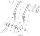
- the linear drive mechanism includes a bracket, a first oil cylinder 29 and a second oil cylinder 30.
- the bracket is slidably disposed between the first connecting seat 11 and the second connecting seat 12, and the bracket is switchable between a first position and a second position.
- the bracket includes a first clamping body 31 and a second clamping body 32, the first clamping body 31 and the second clamping body 32 may have plate-like structures, and the barrels of the first oil cylinder 29 and the second oil cylinder 30 are sandwiched between the first clamping body 31 and the second clamping body 32, and the first clamping body 31 and the second clamping body 32 are connected by a fastener.
- a corresponding surface of the first connecting seat 11 and the second connecting seat 12 is provided with a seat body, the seat body is provided with a chute 34, and the bracket is slidably matched with the chute 34.
- the first oil cylinder 29 is disposed on the bracket. When the bracket is in the first position, the telescopic rod 20 of the first oil cylinder 29 corresponds to the pin shaft hole 13 of the first connecting seat 11.
- the second oil cylinder 30 is also disposed on the bracket and disposed side by side with the first oil cylinders 29. When the bracket is in the second position, the telescopic rod 20 of the second oil cylinder 30 corresponds to the pin shaft hole 13 of the second connecting seat 12.
- the arrangement directions of the first oil cylinder 29 and the second oil cylinder 30 are opposite since the first connecting seat 11 and the second connecting seat 12 are respectively disposed at two ends of the linear drive mechanism.
- the bracket can be controlled to slide, and the first oil cylinder 29 correspond to the pin shaft hole 13 of the first connecting seat 11.
- the bracket is controlled to slide to the second position, the second oil cylinder 30 corresponds to the pin shaft hole 13 of the second connecting seat 12, and the pin shaft 17 on the second connecting seat 12 can be dismounted and mounted through the second oil cylinder 30.
- the overall length formed by the first oil cylinder 29 and the second oil cylinder 30 is short, which can be adapted to the case where the distance between the first connecting seat 11 and the second connecting seat 12 is small.
- a first step referring to FIG. 14 , the connecting assembly 18 between the end portion of the pin shaft 17 and the connecting seat is removed, the bracket is controlled to slide along the chute 34, the telescopic rod 20 of the first oil cylinder 29 is aligned with the in shaft hole 13 on the first connecting seat 11, and the telescopic rod 20 of the first oil cylinder 29 is then operated to stretch to eject the pin shaft 17 on the first connecting seat 11 into the pin shaft hole 13 of an outer lug plate of the first connecting seat 11.
- the telescopic rod 20 of the first oil cylinder 29 is controlled to retract and exit out of the pin shaft hole 13 of the first connecting seat 11.
- a third step as shown in FIG. 15 , the bracket is operated to slide along the chute 34 of the seat body, and the telescopic rod of the second oil cylinder 30 is aligned with the pin shaft hole 13 of the second connecting seat 12.
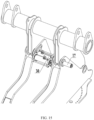
- a fourth step as shown in FIG. 16 , the telescopic rod 20 of the second oil cylinder 30 is controlled to eject the pin shaft 17 on the second connecting seat 12 into the pin shaft hole 13 of an outer lug plate of the second connecting seat 12.
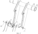
- a fifth step as shown in FIG. 17 , the telescopic rod 20 of the second oil cylinder 30 is controlled to be retracted and thus the gantry 15 may be disengaged from the frame body 16.
- a first step after the gantry 15 is aligned with the pin shaft hole 13 of the frame body 16, the telescopic rod 20 of the second oil cylinder 30 is controlled to stretch into the pin shaft hole 13 and comes into contact with the pin shaft 17.
- the pull rod 25 is inserted into the through hole 23 of the pin shaft 17 of the second connecting seat 12, and is connected with the telescopic rod 20 of the second oil cylinder 30.
- a third step the telescopic rod 20 of the second oil cylinder 30 is controlled to be retracted, and the pin shaft 17 is pulled into the pin shaft hole 13 of the second connecting seat 12 through the pull rod 25 to mounting a pin shaft 17.
- a fourth step the pull rod 25 in the pin shaft 17 of the second connecting seat 12 is removed, and the bracket is controlled to slide along the chute 34 of the seat body and thus the telescopic rod 20 of the first oil cylinder 29 is aligned with the pin shaft hole 13 of the first connecting seat 11.
- the telescopic rod 20 of the first oil cylinder 29 is controlled to stretch into the pin shaft hole 13 of the first connecting seat 11 and the telescopic rod 20 of the first oil cylinder 29 comes into contact with the pin shaft 17 on the first connecting seat 11.
- the pull rod 25 is inserted into the through hole 23 of the pin shaft 17 of the first connecting seat 11, and is connected to the telescopic rod 20 of the first oil cylinder 29.
- a seventh step the telescopic rod 20 of the first oil cylinder 29 is controlled to be retracted, and the pin shaft 17 is pulled into the pin shaft hole 13 of the first connecting seat 11 through the pull rod 25 to mount another pin shaft 17.
- a connecting structure between the pull rod 25 and the telescopic rod 20 includes an external thread 26 disposed at a second end of the pull rod 25 and a threaded hole 21 disposed on the end face of the telescopic rod 20 where the external thread 26 is fitted with threaded hole 21.
- connection between the pull rod 25 and the telescopic rod 20 can be realized by screwing the second end of the pull rod 25 into the threaded hole 21 of the telescopic rod 20.
- the connecting structure between the pull rod 25 and the telescopic rod 20 can also be configured as a snap connection or a keyway connection or the like.
- a head-screwing structure 28 may be disposed on an end surface of the end cap structure 27 of the pull rod 25, and the head-screwing structure 28 may be an elongated protrusion for the operator to hold and rotate.
- guide grooves 35 are disposed on the corresponding surfaces of the first connecting seat 11 and the second connecting seat 12, two ends of the guide groove 35 have closed structures, and guide posts 33 are disposed on two sides of the bracket and are slidably matched with the guide groove 35, that is, the guide post 33 can slide between a first end and a second end of the guide groove 35.
- the guide post 33 When the bracket is in the first position, the guide post 33 abuts against the first end of the guide groove 35; when the bracket is in the second position, the guide post 33 abuts against the second end of the guide groove 35, and two ends of the guide groove 35 can have a limiting effect on the guide post 33.
- the guide post 33 on the bracket is displaced along the chute 34 at the same time.
- the bracket can no longer move and is in the first position state, and the telescopic rod 20 of the first oil cylinder 29 corresponds to the pin shaft hole 13 of the first connecting seat 11.
- the bracket can no longer move and is in the second position, and the telescopic rod 20 of the second oil cylinder 30 corresponds to the pin shaft hole 13 of the second connecting seat 12.
- a connecting assembly is detachably disposed at the end portion of the pin shaft 17 and is used for being connected with sides of the connecting seats.
- the end portion of the pin shaft 17 is provided with an annular groove 24, and the connecting assembly 18 may be a non-enclosed connecting flange sleeved in the annular groove 24.
- the connecting flange can be sleeved within the annular groove 24 since the connecting flange is a non-enclosed structure.
- the connecting seat and the connecting flange are provided with corresponding bolt holes, the connecting flange can be fixedly connected to the connecting assembly 18 by bolts inserted inside the bolt holes and then the pin shaft 17 is fixedly connected.
- An embodiment of the present application further provides a frame body connecting structure, which includes a first frame body and a second frame body.
- the first frame body may be the frame body 16 in the above-mentioned embodiments
- the second frame body may be the gantry 15 in the above-mentioned embodiments.
- the first frame body and the second frame body may also be other frame bodies used on the mechanical equipment.
- Each of the first frame body and the second frame body is provided with a connecting seat, each connecting seat is provided with a pin shaft hole, the second frame body is connected with the first frame body through a pin shaft, and the pin shaft is provided with a through hole.
- the pin shaft dismounting and mounting device is connected with the first frame body or the second frame body, the pin shaft dismounting and mounting device may be the pin shaft dismounting and mounting device in any of the above embodiments, and the telescopic rod corresponds to the pin shaft.
- the connecting seat includes a first connecting seat 11 and a second connecting seat 12 disposed at intervals, and a bracket is slidably disposed between the first connecting seat 11 and the second connecting seat 12, and may be switchable between a first position in which the telescopic rod of the first oil cylinder 29 corresponds to the pin shaft hole of the first connecting seat 11 and a second position in which the telescopic rod of the second oil cylinder 30 corresponds to the pin shaft hole of the second connecting seat 12.
- An embodiment of the present application further provides work machine, including the above-mentioned frame body connecting structure.
- the pin shaft 17 can be dismounted and mounted conveniently, and the problems of wear and deformation of the piston rod are solved.
Landscapes
- Engineering & Computer Science (AREA)
- Mechanical Engineering (AREA)
- General Engineering & Computer Science (AREA)
- Mining & Mineral Resources (AREA)
- Civil Engineering (AREA)
- Structural Engineering (AREA)
- Physics & Mathematics (AREA)
- Fluid Mechanics (AREA)
- Actuator (AREA)
- Automatic Assembly (AREA)
- Jib Cranes (AREA)
- Hand Tools For Fitting Together And Separating, Or Other Hand Tools (AREA)
Claims (9)
- Stiftschaft-Demontage- und Montagevorrichtung zum Demontieren und Montieren eines Stiftschafts (17) auf einem Verbindungssitz, wobei der Stiftschaft (17) mit einem Durchgangsloch (23) entlang einer axialen Richtung des Stiftschafts versehen ist, aufweisend:einen linearen Antriebsmechanismus, der Teleskopstangen (20) umfasst, wobei die Teleskopstangen (20) von beiden Enden des linearen Antriebsmechanismus ausziehbar sind; undeine Zugstange (25), die so konfiguriert ist, dass sie durch das Durchgangsloch (23) verläuft, wobei ein erstes Ende der Zugstange (25) mit einer Endkappenstruktur (27) versehen ist, wobei eine Verbindungsstruktur zwischen einem zweiten Ende der Zugstange (25) und einem Endabschnitt jeder Teleskopstange (20) angeordnet ist;
dadurch gekennzeichnet, dass:eine Länge des Hauptkörpers der Zugstange (25) größer ist als eine Länge des Stiftschafts (17) und das zweite Ende der Zugstange (25) sich von einem Ende aus erstreckt, an dem sich das Durchgangsloch (23) des Stiftschafts (17) befindet, und sich von einem anderen Ende des Stiftschafts (17) aus erstreckt,ein Durchmesser jeder Teleskopstange (20) größer ist als ein Durchmesser des Durchgangslochs (23);der Stiftschaft (17) durch eine der Teleskopstangen (20) des linearen Antriebsmechanismus in ein Stiftschaftloch (13) gezogen oder aus einem Stiftschaftloch (13) herausgeschoben wird. - Vorrichtung nach Anspruch 1, wobei
der linearen Antriebsmechanismus ein doppelendiger Ölzylinder (19) ist. - Vorrichtung nach Anspruch 1, wobei der lineare Antriebsmechanismus Folgendes aufweist:eine Halterung;einen ersten Ölzylinder (29), der an der Halterung angeordnet ist; undeinen zweiten Ölzylinder (30), der an der Halterung angeordnet ist und Seite an Seite mit dem ersten Ölzylinder (29) angeordnet ist, wobei die Teleskopstange (20) des zweiten Ölzylinders (30) und des ersten Ölzylinders (29) in einer entgegengesetzten Richtung angeordnet sind.
- Vorrichtung nach Anspruch 3, wobeidie Halterung einen ersten Klemmkörper (31) und einen zweiten Klemmkörper (32) aufweist,die Zylinder des ersten Ölzylinders (29) und des zweiten Ölzylinders (30) fest zwischen dem ersten Klemmkörper (31) und dem zweiten Klemmkörper (32) angeordnet sind, unddie Teleskopstangen (20) des zweiten Ölzylinders (30) und des ersten Ölzylinders (29) in der Lage sind, durch die Halterung hindurchzugehen bzw. sich aus dem Zylinder zu strecken.
- Vorrichtung nach Anspruch 2 oder 3 ferner aufweisend
ein Umschaltventil (22), das so konfiguriert ist, dass es die Ausfahrrichtung der Teleskopstange (20) steuert. - Vorrichtung nach Anspruch 1, wobei die Verbindungsstruktur Folgendes aufweist:ein Außengewinde (26), das an dem zweiten Ende der Zugstange (25) angeordnet ist; undein Gewindeloch (21), das an einer Endfläche der Teleskopstange (20) angeordnet ist, wobei das Außengewinde (26) in das Gewindeloch (21) eingepasst ist.
- Rahmenkörper-Verbindungsstruktur, aufweisend:einen ersten Rahmenkörper (16),einen zweiten Rahmenkörper, wobei sowohl der erste Rahmenkörper (16) als auch der zweite Rahmenkörper mit Verbindungssitzen (11, 12) versehen sind, wobei jeder Verbindungssitz (11, 12) mit einem Stiftschaftloch (13) versehen ist und der zweite Rahmenkörper mit dem ersten Rahmenkörper (16) durch einen Stiftschaft (17) verbunden ist, wobei der Stiftschaft (17) mit einem Durchgangsloch (23) versehen ist, undeine mit dem ersten Rahmenkörper (16) oder dem zweiten Rahmenkörper verbundene Stiftschaft-Demontage- und Montagevorrichtung, wobei die Stiftschaft-Demontage- und Montagevorrichtung die Stiftschaft-Demontage- und Montagevorrichtung nach einem der Ansprüche 3 bis 4 ist.
- Rahmenkörper-Verbindungsstruktur nach Anspruch 7, wobeidie Halterung verschiebbar zwischen einem ersten Verbindungssitz (11) und einem zweiten Verbindungssitz (12) angeordnet ist, unddie Halterung zwischen einer ersten Position, in der die Teleskopstange (20) des ersten Ölzylinders (29) mit dem Stiftschaftloch (13) des ersten Verbindungssitzes (11) ausgerichtet ist, und einer zweiten Position, in der die Teleskopstange (20) des zweiten Ölzylinders (30) mit dem Stiftschaftloch (13) des zweiten Verbindungssitzes (12) ausgerichtet ist, umschaltbar ist.
- Arbeitsmaschine, umfassend die Rahmenkörper-Verbindungsstruktur nach Anspruch 7 oder 8.
Applications Claiming Priority (2)
| Application Number | Priority Date | Filing Date | Title |
|---|---|---|---|
| CN202111124180.0A CN113695871B (zh) | 2021-09-24 | 2021-09-24 | 销轴拆装装置、架体连接结构及作业机械 |
| PCT/CN2022/073482 WO2023045194A1 (zh) | 2021-09-24 | 2022-01-24 | 销轴拆装装置、架体连接结构及作业机械 |
Publications (4)
| Publication Number | Publication Date |
|---|---|
| EP4180169A1 EP4180169A1 (de) | 2023-05-17 |
| EP4180169A4 EP4180169A4 (de) | 2023-10-11 |
| EP4180169B1 true EP4180169B1 (de) | 2024-09-18 |
| EP4180169C0 EP4180169C0 (de) | 2024-09-18 |
Family
ID=84441561
Family Applications (1)
| Application Number | Title | Priority Date | Filing Date |
|---|---|---|---|
| EP22772397.0A Active EP4180169B1 (de) | 2021-09-24 | 2022-01-24 | Stiftwellendemontage- und -montagevorrichtung |
Country Status (4)
| Country | Link |
|---|---|
| US (1) | US11786998B2 (de) |
| EP (1) | EP4180169B1 (de) |
| JP (1) | JP7446479B2 (de) |
| KR (1) | KR102767324B1 (de) |
Families Citing this family (4)
| Publication number | Priority date | Publication date | Assignee | Title |
|---|---|---|---|---|
| US12583084B2 (en) | 2023-01-06 | 2026-03-24 | Tiger Tool International Incorporated | Drive plate systems, methods, and apparatus for a press tool |
| US20250060007A1 (en) * | 2023-08-14 | 2025-02-20 | Tiger Tool International Incorporated | Adaptable bushing assembly removal coupler and systems and methods for removing bushing assemblies |
| CN117644379B (zh) * | 2024-01-25 | 2024-04-09 | 苏州猎奇智能设备有限公司 | 一种气弹簧端部支架高效自动组装设备 |
| CN119734075B (zh) * | 2025-01-02 | 2025-09-23 | 大连理工大学 | 一种折叠铰接偶件非通透孔内销轴铰接装配装置和方法 |
Family Cites Families (21)
| Publication number | Priority date | Publication date | Assignee | Title |
|---|---|---|---|---|
| US3638294A (en) * | 1970-01-20 | 1972-02-01 | Walter F Durant | Wheel puller |
| JPS59123081U (ja) | 1983-02-08 | 1984-08-18 | 日立建機株式会社 | 建設機械に於けるピン着脱装置 |
| US4860539A (en) * | 1988-06-09 | 1989-08-29 | Terex Corporation | Vehicle stabilizer apparatus and stabilizer actuator component thereof |
| JP2001295273A (ja) * | 2000-04-10 | 2001-10-26 | Nippon Sharyo Seizo Kaisha Ltd | ピン式連結装置 |
| US6412157B1 (en) * | 2000-09-13 | 2002-07-02 | Keith Arthur Gray | Device for displacing tubular elements relative to one another |
| DE10297276T5 (de) | 2001-09-26 | 2004-09-23 | Hanwoo Tnc Corporation | Aufsatzkopplungsvorrichtung für Schwermaschinen |
| JP5222568B2 (ja) * | 2008-01-18 | 2013-06-26 | 株式会社加藤製作所 | 移動式クレーン |
| CN201889623U (zh) | 2010-10-28 | 2011-07-06 | 三一集团有限公司 | 工程车辆的插、拔销装置和越野正面吊运机 |
| JP2013253400A (ja) * | 2012-06-06 | 2013-12-19 | Hitachi Constr Mach Co Ltd | 油圧パワーユニットの着脱装置 |
| CN202726418U (zh) | 2012-06-28 | 2013-02-13 | 三一汽车起重机械有限公司 | 一种插拔销装置及工程机械 |
| CN203045279U (zh) | 2012-12-11 | 2013-07-10 | 北汽福田汽车股份有限公司 | 一种穿销装置 |
| JP6231320B2 (ja) * | 2013-07-23 | 2017-11-15 | 株式会社タダノ | アウトリガ連結ロック装置 |
| JP5861682B2 (ja) | 2013-09-11 | 2016-02-16 | コベルコクレーン株式会社 | クローラクレーンのブームフットピン着脱装置 |
| CN203486805U (zh) | 2013-10-18 | 2014-03-19 | 中联重科股份有限公司 | 具有插拔销装置的支腿结构及具有该支腿结构的起重机 |
| WO2015184493A1 (en) | 2014-06-04 | 2015-12-10 | Dt-Hiload Australia Pty Ltd | Device for inserting/removing pivot pins |
| CN203974398U (zh) | 2014-07-22 | 2014-12-03 | 鞍山强锋久盛科技发展有限公司 | 重型矿用汽车轮胎拆装机 |
| CN205802811U (zh) | 2016-07-12 | 2016-12-14 | 郑州科润机电工程有限公司 | 适用于平臂塔机臂架标准节之间连接销轴快速插拔的装置 |
| CN209779456U (zh) | 2019-01-21 | 2019-12-13 | 中国船舶重工集团应急预警与救援装备股份有限公司 | 一种连桥机构 |
| JP7159893B2 (ja) | 2019-02-04 | 2022-10-25 | コベルコ建機株式会社 | 連結装置 |
| JP6891920B2 (ja) * | 2019-05-28 | 2021-06-18 | コベルコ建機株式会社 | 建設機械の油圧ピン抜け止め構造 |
| CN113695871B (zh) | 2021-09-24 | 2022-07-29 | 北京三一智造科技有限公司 | 销轴拆装装置、架体连接结构及作业机械 |
-
2022
- 2022-01-24 US US17/928,588 patent/US11786998B2/en active Active
- 2022-01-24 EP EP22772397.0A patent/EP4180169B1/de active Active
- 2022-01-24 JP JP2022562127A patent/JP7446479B2/ja active Active
- 2022-01-24 KR KR1020227040770A patent/KR102767324B1/ko active Active
Also Published As
| Publication number | Publication date |
|---|---|
| JP7446479B2 (ja) | 2024-03-08 |
| EP4180169A4 (de) | 2023-10-11 |
| KR102767324B1 (ko) | 2025-02-12 |
| KR20220162845A (ko) | 2022-12-08 |
| JP2023542062A (ja) | 2023-10-05 |
| US11786998B2 (en) | 2023-10-17 |
| EP4180169C0 (de) | 2024-09-18 |
| EP4180169A1 (de) | 2023-05-17 |
| US20230211442A1 (en) | 2023-07-06 |
Similar Documents
| Publication | Publication Date | Title |
|---|---|---|
| EP4180169B1 (de) | Stiftwellendemontage- und -montagevorrichtung | |
| CN113695871B (zh) | 销轴拆装装置、架体连接结构及作业机械 | |
| CN108817437B (zh) | 一种柔性内径支撑装配装置 | |
| CN107398698B (zh) | 压头、衬套压装装置及压装方法 | |
| DE3918484C2 (de) | Reifenbe- und Reifenentlademechanismus eines Reifenkühlers bei einer Reifenvulkanisiermaschine | |
| CN210908832U (zh) | 齿轮轴承拆卸装置 | |
| KR102298816B1 (ko) | 밸브 시트를 분해 및 설치하기 위한 지그 장치 | |
| CN219189367U (zh) | 一种夹紧装置 | |
| CN111842502B (zh) | 一种轧机辊轴辅助工装 | |
| CN214081235U (zh) | 一种新型的过盈装配拆卸辅助工具 | |
| CN215970937U (zh) | 一种用于脚轮锁止和支撑的组合机构 | |
| CN117484923A (zh) | 一种多截面拉挤牵引装置 | |
| CN212442575U (zh) | 一种轧机辊轴辅助工装 | |
| CN210411956U (zh) | 一种挤压轴快速更换与锁紧装置 | |
| EP1402188B1 (de) | Arbeitszylinder | |
| CN212825115U (zh) | 一种辊轴拆卸机械手及辊轴拆卸装置 | |
| CN215880669U (zh) | 一种引动器端盖拆卸装置 | |
| CN218746010U (zh) | 臂架装轴装置 | |
| CN116061131B (zh) | 一种膨化机螺杆整体拆除装置 | |
| CN223276908U (zh) | 一种粘性危废物料挤压式切割机 | |
| CN221779779U (zh) | 液压缸的钢球锁紧装置 | |
| CN116078823B (zh) | 悬臂轧机辊环护罩拆装执行器 | |
| CN219359225U (zh) | 一种轴类产品用夹具 | |
| CN110193923B (zh) | 热成型机的锁模装置 | |
| CN221364428U (zh) | 一种打磨轮快换装机构 |
Legal Events
| Date | Code | Title | Description |
|---|---|---|---|
| STAA | Information on the status of an ep patent application or granted ep patent |
Free format text: STATUS: UNKNOWN |
|
| STAA | Information on the status of an ep patent application or granted ep patent |
Free format text: STATUS: THE INTERNATIONAL PUBLICATION HAS BEEN MADE |
|
| PUAI | Public reference made under article 153(3) epc to a published international application that has entered the european phase |
Free format text: ORIGINAL CODE: 0009012 |
|
| STAA | Information on the status of an ep patent application or granted ep patent |
Free format text: STATUS: REQUEST FOR EXAMINATION WAS MADE |
|
| 17P | Request for examination filed |
Effective date: 20220926 |
|
| AK | Designated contracting states |
Kind code of ref document: A1 Designated state(s): AL AT BE BG CH CY CZ DE DK EE ES FI FR GB GR HR HU IE IS IT LI LT LU LV MC MK MT NL NO PL PT RO RS SE SI SK SM TR |
|
| A4 | Supplementary search report drawn up and despatched |
Effective date: 20230913 |
|
| RIC1 | Information provided on ipc code assigned before grant |
Ipc: B23P 19/027 20060101AFI20230907BHEP |
|
| RIC1 | Information provided on ipc code assigned before grant |
Ipc: F16C 11/04 20060101ALN20240416BHEP Ipc: F16C 3/03 20060101ALN20240416BHEP Ipc: E02F 9/22 20060101ALI20240416BHEP Ipc: E02F 9/00 20060101ALI20240416BHEP Ipc: B23P 19/027 20060101AFI20240416BHEP |
|
| GRAP | Despatch of communication of intention to grant a patent |
Free format text: ORIGINAL CODE: EPIDOSNIGR1 |
|
| STAA | Information on the status of an ep patent application or granted ep patent |
Free format text: STATUS: GRANT OF PATENT IS INTENDED |
|
| INTG | Intention to grant announced |
Effective date: 20240531 |
|
| GRAS | Grant fee paid |
Free format text: ORIGINAL CODE: EPIDOSNIGR3 |
|
| DAV | Request for validation of the european patent (deleted) | ||
| DAX | Request for extension of the european patent (deleted) | ||
| GRAA | (expected) grant |
Free format text: ORIGINAL CODE: 0009210 |
|
| STAA | Information on the status of an ep patent application or granted ep patent |
Free format text: STATUS: THE PATENT HAS BEEN GRANTED |
|
| AK | Designated contracting states |
Kind code of ref document: B1 Designated state(s): AL AT BE BG CH CY CZ DE DK EE ES FI FR GB GR HR HU IE IS IT LI LT LU LV MC MK MT NL NO PL PT RO RS SE SI SK SM TR |
|
| REG | Reference to a national code |
Ref country code: GB Ref legal event code: FG4D |
|
| REG | Reference to a national code |
Ref country code: CH Ref legal event code: EP |
|
| REG | Reference to a national code |
Ref country code: IE Ref legal event code: FG4D |
|
| REG | Reference to a national code |
Ref country code: DE Ref legal event code: R096 Ref document number: 602022006248 Country of ref document: DE |
|
| U01 | Request for unitary effect filed |
Effective date: 20241017 |
|
| U07 | Unitary effect registered |
Designated state(s): AT BE BG DE DK EE FI FR IT LT LU LV MT NL PT RO SE SI Effective date: 20241031 |
|
| PG25 | Lapsed in a contracting state [announced via postgrant information from national office to epo] |
Ref country code: NO Free format text: LAPSE BECAUSE OF FAILURE TO SUBMIT A TRANSLATION OF THE DESCRIPTION OR TO PAY THE FEE WITHIN THE PRESCRIBED TIME-LIMIT Effective date: 20241218 |
|
| PG25 | Lapsed in a contracting state [announced via postgrant information from national office to epo] |
Ref country code: GR Free format text: LAPSE BECAUSE OF FAILURE TO SUBMIT A TRANSLATION OF THE DESCRIPTION OR TO PAY THE FEE WITHIN THE PRESCRIBED TIME-LIMIT Effective date: 20241219 |
|
| PG25 | Lapsed in a contracting state [announced via postgrant information from national office to epo] |
Ref country code: HR Free format text: LAPSE BECAUSE OF FAILURE TO SUBMIT A TRANSLATION OF THE DESCRIPTION OR TO PAY THE FEE WITHIN THE PRESCRIBED TIME-LIMIT Effective date: 20240918 |
|
| PG25 | Lapsed in a contracting state [announced via postgrant information from national office to epo] |
Ref country code: RS Free format text: LAPSE BECAUSE OF FAILURE TO SUBMIT A TRANSLATION OF THE DESCRIPTION OR TO PAY THE FEE WITHIN THE PRESCRIBED TIME-LIMIT Effective date: 20241218 |
|
| PG25 | Lapsed in a contracting state [announced via postgrant information from national office to epo] |
Ref country code: RS Free format text: LAPSE BECAUSE OF FAILURE TO SUBMIT A TRANSLATION OF THE DESCRIPTION OR TO PAY THE FEE WITHIN THE PRESCRIBED TIME-LIMIT Effective date: 20241218 Ref country code: NO Free format text: LAPSE BECAUSE OF FAILURE TO SUBMIT A TRANSLATION OF THE DESCRIPTION OR TO PAY THE FEE WITHIN THE PRESCRIBED TIME-LIMIT Effective date: 20241218 Ref country code: HR Free format text: LAPSE BECAUSE OF FAILURE TO SUBMIT A TRANSLATION OF THE DESCRIPTION OR TO PAY THE FEE WITHIN THE PRESCRIBED TIME-LIMIT Effective date: 20240918 Ref country code: GR Free format text: LAPSE BECAUSE OF FAILURE TO SUBMIT A TRANSLATION OF THE DESCRIPTION OR TO PAY THE FEE WITHIN THE PRESCRIBED TIME-LIMIT Effective date: 20241219 |
|
| U20 | Renewal fee for the european patent with unitary effect paid |
Year of fee payment: 4 Effective date: 20250122 |
|
| PG25 | Lapsed in a contracting state [announced via postgrant information from national office to epo] |
Ref country code: IS Free format text: LAPSE BECAUSE OF FAILURE TO SUBMIT A TRANSLATION OF THE DESCRIPTION OR TO PAY THE FEE WITHIN THE PRESCRIBED TIME-LIMIT Effective date: 20250118 |
|
| PG25 | Lapsed in a contracting state [announced via postgrant information from national office to epo] |
Ref country code: SM Free format text: LAPSE BECAUSE OF FAILURE TO SUBMIT A TRANSLATION OF THE DESCRIPTION OR TO PAY THE FEE WITHIN THE PRESCRIBED TIME-LIMIT Effective date: 20240918 |
|
| PG25 | Lapsed in a contracting state [announced via postgrant information from national office to epo] |
Ref country code: ES Free format text: LAPSE BECAUSE OF FAILURE TO SUBMIT A TRANSLATION OF THE DESCRIPTION OR TO PAY THE FEE WITHIN THE PRESCRIBED TIME-LIMIT Effective date: 20240918 |
|
| PG25 | Lapsed in a contracting state [announced via postgrant information from national office to epo] |
Ref country code: PL Free format text: LAPSE BECAUSE OF FAILURE TO SUBMIT A TRANSLATION OF THE DESCRIPTION OR TO PAY THE FEE WITHIN THE PRESCRIBED TIME-LIMIT Effective date: 20240918 Ref country code: CZ Free format text: LAPSE BECAUSE OF FAILURE TO SUBMIT A TRANSLATION OF THE DESCRIPTION OR TO PAY THE FEE WITHIN THE PRESCRIBED TIME-LIMIT Effective date: 20240918 |
|
| PG25 | Lapsed in a contracting state [announced via postgrant information from national office to epo] |
Ref country code: SK Free format text: LAPSE BECAUSE OF FAILURE TO SUBMIT A TRANSLATION OF THE DESCRIPTION OR TO PAY THE FEE WITHIN THE PRESCRIBED TIME-LIMIT Effective date: 20240918 |
|
| PLBE | No opposition filed within time limit |
Free format text: ORIGINAL CODE: 0009261 |
|
| STAA | Information on the status of an ep patent application or granted ep patent |
Free format text: STATUS: NO OPPOSITION FILED WITHIN TIME LIMIT |
|
| 26N | No opposition filed |
Effective date: 20250619 |
|
| REG | Reference to a national code |
Ref country code: CH Ref legal event code: PL |
|
| PG25 | Lapsed in a contracting state [announced via postgrant information from national office to epo] |
Ref country code: MC Free format text: LAPSE BECAUSE OF FAILURE TO SUBMIT A TRANSLATION OF THE DESCRIPTION OR TO PAY THE FEE WITHIN THE PRESCRIBED TIME-LIMIT Effective date: 20240918 |
|
| PG25 | Lapsed in a contracting state [announced via postgrant information from national office to epo] |
Ref country code: CH Free format text: LAPSE BECAUSE OF NON-PAYMENT OF DUE FEES Effective date: 20250131 |
|
| PG25 | Lapsed in a contracting state [announced via postgrant information from national office to epo] |
Ref country code: IE Free format text: LAPSE BECAUSE OF NON-PAYMENT OF DUE FEES Effective date: 20250124 |
|
| U20 | Renewal fee for the european patent with unitary effect paid |
Year of fee payment: 5 Effective date: 20260127 |
|
| PGFP | Annual fee paid to national office [announced via postgrant information from national office to epo] |
Ref country code: GB Payment date: 20260123 Year of fee payment: 5 |