EP4180140A1 - Machine à plier - Google Patents
Machine à plier Download PDFInfo
- Publication number
- EP4180140A1 EP4180140A1 EP21208406.5A EP21208406A EP4180140A1 EP 4180140 A1 EP4180140 A1 EP 4180140A1 EP 21208406 A EP21208406 A EP 21208406A EP 4180140 A1 EP4180140 A1 EP 4180140A1
- Authority
- EP
- European Patent Office
- Prior art keywords
- bending
- holding device
- bending machine
- tool
- machine according
- Prior art date
- Legal status (The legal status is an assumption and is not a legal conclusion. Google has not performed a legal analysis and makes no representation as to the accuracy of the status listed.)
- Withdrawn
Links
- 238000005452 bending Methods 0.000 title claims abstract description 365
- 238000001514 detection method Methods 0.000 claims description 3
- 230000001960 triggered effect Effects 0.000 claims 1
- 239000002184 metal Substances 0.000 description 11
- 238000000034 method Methods 0.000 description 11
- 230000008569 process Effects 0.000 description 11
- 230000008859 change Effects 0.000 description 6
- 230000002265 prevention Effects 0.000 description 3
- 230000008901 benefit Effects 0.000 description 2
- 230000008878 coupling Effects 0.000 description 2
- 238000010168 coupling process Methods 0.000 description 2
- 238000005859 coupling reaction Methods 0.000 description 2
- 230000000694 effects Effects 0.000 description 2
- 230000007246 mechanism Effects 0.000 description 2
- 238000003462 Bender reaction Methods 0.000 description 1
- 230000009471 action Effects 0.000 description 1
- 230000006835 compression Effects 0.000 description 1
- 238000007906 compression Methods 0.000 description 1
- 230000001419 dependent effect Effects 0.000 description 1
- 238000011161 development Methods 0.000 description 1
- 230000018109 developmental process Effects 0.000 description 1
- 229920001971 elastomer Polymers 0.000 description 1
- 239000000806 elastomer Substances 0.000 description 1
- 230000003993 interaction Effects 0.000 description 1
- 238000004519 manufacturing process Methods 0.000 description 1
Images


Classifications
-
- B—PERFORMING OPERATIONS; TRANSPORTING
- B21—MECHANICAL METAL-WORKING WITHOUT ESSENTIALLY REMOVING MATERIAL; PUNCHING METAL
- B21D—WORKING OR PROCESSING OF SHEET METAL OR METAL TUBES, RODS OR PROFILES WITHOUT ESSENTIALLY REMOVING MATERIAL; PUNCHING METAL
- B21D5/00—Bending sheet metal along straight lines, e.g. to form simple curves
- B21D5/02—Bending sheet metal along straight lines, e.g. to form simple curves on press brakes without making use of clamping means
- B21D5/0209—Tools therefor
- B21D5/0236—Tool clamping
Definitions
- the invention relates to a bending machine for forming workpieces by bending.
- Bending machines such as e.g. press brakes, are often designed for operation with different bending tools, which bring about the bending of a corresponding workpiece during operation.
- the exchange of bending tools requires the opening or closing of a corresponding holding device on the bending machine.
- holding devices that have to be opened or closed manually by a human operator.
- Such manual holding devices require the physical effort of the operator and require long changing times for the bending tools.
- Automatic holding devices are also known from the prior art, in which, with a suitable actuator, the holding device can be released to remove the bending tool or closed to fix the bending tool.
- a suitable actuator for example, hydraulic, pneumatic or electromechanical actuators are used as actuators.
- Automatic holding devices relieve the human operator, but result in high manufacturing costs and are prone to errors.
- the pamphlet DE 30 26 847 A1 discloses a press brake in which a bending tool is releasably clamped in a tool holder via a hydraulically or pneumatically pressurizable swellable body.
- the document DE 195 13 576 A1 discloses a press brake having a clamping device for releasably attaching a tool, the clamping device being hydraulically operable.
- the document WO 2015/164483 A1 describes a tool holder in which the tool is fixed using a clamping device that is actuated by a cylinder charged with compressed air.
- the object of the invention is to provide a bending machine with a holding device for bending tools, the holding device enabling automatic fixing and release of the bending tools in a simple manner.
- the bending machine according to the invention has a bending beam which can be moved at least in one working direction of the bending machine in order to deform a workpiece by bending along a bending line, the bending line in a width direction the bending machine runs.
- the bending machine contains a holding device in order to fix at least one bending tool on the bending machine.
- a release means is also provided on the bending machine in order to move the holding device from a closed position, in which the at least one bending tool is fixed, to an open position releasing the at least one bending tool when it is actuated.
- the bending machine according to the invention is designed in such a way that a movement of the bending beam towards a predetermined release position actuates the release means when the predetermined release position is reached.
- the bending machine according to the invention has the advantage that the movement of the bending beam is used not only within the framework of the bending of the workpiece, but also to release bending tools held in the bending machine. In this way, a simple mechanism is created to allow changing of bending tools on the bending machine.
- the at least one bending tool is held on the bending beam when the holding device is in the closed position. Nevertheless, it is also possible that the at least one bending tool is held on a bending beam other than the bending beam whose movement actuates the release means.
- the at least one bending tool can be fixed in different ways depending on the design of the bending machine.
- the holding device provided in the bending machine is designed to fix the at least one bending tool in a positive and/or non-positive manner.
- a form-fitting fixation can be effected, for example, via a slide control.
- the holding device exerts a holding force on the at least one bending tool in order to fix it on the bending machine, with the holding force on the at least one bending tool being terminated when the release means is actuated and the holding device thereby being released into the at least one bending tool , open position is brought.
- the bending machine according to the invention is designed such that the movement of the bending beam when the predetermined release position is reached generates a release force which is exerted on the holding device by the release means in order to unfix the at least one bending tool.
- This variant of the invention is preferably combined with a non-positive fixing of the at least one bending tool, so that the release force ends the holding force exerted by the holding device on the at least one bending tool.
- the release means can generate the release force directly by mechanical action on the holding device.
- the release means can include a hydraulic circuit, for example, which is switched on when the release position is reached and then generates the release force via hydraulic pressure.
- the bending machine according to the invention is designed in such a way that the movement of the bending beam towards the predetermined release position is a movement in the working direction of the bending machine.
- This embodiment is preferably used when the bending machine is a press brake.
- the movement of the bending beam towards the predetermined release position is a movement in a direction deviating from the working direction, the deviating direction preferably corresponding to the width direction of the bending machine.
- This variant is preferably used when the bending machine is a panel bender.
- the release means is immovably attached to the bending machine, whereas the holding device can be moved together with the bending beam towards the predetermined release position.
- the holding device is preferably provided on the bending beam, the movement of which actuates the release means in order to hold the at least one bending tool on this bending beam.
- the release means can also be movable with the bending beam, the movement of which actuates the release means, whereas the holding device is immovably attached to the bending machine in order to hold the at least one bending tool on a (stationary) bending beam other than the bending beam whose Movement actuates the release agent.
- the release means contains one or more contact elements, preferably one or more wedges. These contact elements are arranged in such a way that when the predetermined release position is reached, they mechanically contact the holding device and thereby end the fixing of the at least one bending tool.
- the release of the at least one bending tool can be achieved by a simple mechanical structure.
- the exertion of a holding force generated by the holding device on the at least one bending tool is terminated by means of the contact element or elements.
- a respective contact element is designed in such a way that when the predetermined release position is reached, it presses against at least one contact surface of the holding device and thereby triggers a movement on the holding device, thereby ending the fixing of the at least one bending tool.
- the exertion of a holding force generated by the holding device on the at least one bending tool is preferably terminated.
- the holding device is a clamping device which is designed in such a way that it exerts a holding force in the form of a clamping force on the at least one bending tool in order to fix the at least one bending tool.
- the holding device comprises one or more elastic means, which are prestressed in the holding device in order to thereby generate a holding force for fixing the at least one bending tool.
- the elastic means or means can be designed differently, for example as one or more springs, such as disk springs, and/or as one or more elastomers and the like.
- the holding device comprises one or more anti-loss devices to hold the at least one bending tool loosely in the holding device when the holding device is open.
- the holding device comprises one or more positioning means in order to ensure that the at least one bending tool moves into a specified position when the specified release position is reached, in which the at least one bending tool held by the holding device.
- a sensor system is provided in the bending machine according to the invention, which is configured to detect the approach of the bending beam to the predetermined release position as a detection event.
- the bending machine is preferably designed in such a way that when the detection event is detected, a message is output via a user interface of the bending machine, such as a display. In this way, an operator of the bending machine is informed that the bending machine is in a state in which the bending tools can be changed.
- the release means can be moved into a parking position on the bending machine, in which the release means cannot be actuated by moving the bending beam. In this way, an unintentional loosening of the fixation of the at least one bending tool can be prevented.
- the bending machine according to the invention is a press brake for freely bending a workpiece between a movable upper beam and a stationary lower beam.
- the bending beam, the movement of which actuates the release means, is the upper beam.
- the holding device is provided on the upper beam in order to hold the at least one bending tool on the upper beam, with the release means being arranged immovably adjacent to the upper beam and due to the movement of the upper beam in the working direction away from the Lower beam the specified release position is reached.
- the movement of the upper beam that is already present for bending the workpiece is also used to release the at least one bending tool in a simple manner.
- the bending machine according to the invention is a panel bender, which is configured in such a way that the workpiece—in contrast to free bending in a press brake—is fixed during bending.
- the holding device is provided on the bending beam, the movement of which actuates the release means in order to hold the at least one bending tool on this bending beam, with the specified release position being outside a working area in which bending is carried out by the bending beam takes place.
- the bending beam can preferably be moved into the predetermined release position in the width direction of the panel bender.
- this includes a primary bending beam, which is movable exclusively in the working direction and perpendicular to the plane spanned by the working direction and the width direction, and a secondary bending beam, which is the bending beam whose Movement actuates the release means, wherein the secondary beam is movably mounted on the primary beam in the width direction.
- the secondary bending beam thus follows the movement of the primary bending beam, but can also be moved in the width direction relative to the primary bending beam.
- the primary bending beam comprises one or more bending tools which are firmly connected to it and cannot be exchanged without additional aids.
- corresponding bending tools can be changed on the secondary bending beam.
- the secondary bending beam is therefore always used as required when bending processes have to be carried out on the workpiece with special bending tools.
- the spatial orientation of the corresponding bending machine is illustrated by a Cartesian coordinate system with an x-axis, y-axis and z-axis.
- the z-axis represents the height direction
- the y-axis represents the width direction of the bending machine in which the bend line runs
- the x-axis represents the direction perpendicular to the y-axis and z-axis.
- the workpiece to be bent is introduced into the bending machine by an operator or, if necessary, automatically.
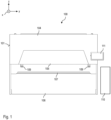
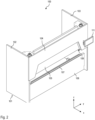
- a first embodiment of a bending machine according to the invention in the form of a press brake is described below.
- This press brake is in 1 in top view and in 2 shown in perspective view and designated by reference numeral 100 . Only the components of the press brake that are essential to the invention are shown.
- the press brake 100 includes a machine body 101 fixed to the floor, which includes two side stands 102, 103 and a front plate 104. As shown in FIG. A stationary lower beam 106 and an upper beam 105 that can be moved in the z-direction extend in a manner known per se between the side stands 102 and 103.
- the upper beam represents a bending beam within the meaning of the claims there is a tool holder 107 to which suitable lower tools are attached during operation of the bending machine. Analog 105 bending tools are fixed for the corresponding bending process on the underside of the upper beam, according to 1 and 2 two such bending tools 109 are provided.
- the press brake 100 is used for bending sheet metal.
- the sheet metal is introduced along the x-axis into the work area between lower beam 106 and upper beam 105, and then the upper beam 105 is moved downwards to form the sheet metal, so that the bending tools 109 press into the sheet metal and deform it appropriately.
- the movement of the upper beam 105 is by means of a hydraulic system in the form of two hydraulic cylinders 112, 112', which can be seen from the rear view of FIG 3 are evident.
- an in 1 only schematically indicated control device 110 and a user interface 111 in the form of a touch display is provided, which is arranged in the right-hand area of the press brake on the front panel 104.
- the corresponding bending tools 109 Since high forces act on the sheet during the bending process, the corresponding bending tools 109 must be firmly fixed in the upper beam 105. At the same time, however, it must also be ensured that the bending tools 109 can be exchanged. This is ensured by a holding device 113 which fixes the corresponding bending tools 109 to the upper beam 105, it being possible for the holding device to be opened with a release means 116 in order to remove the bending tools.
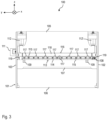
- 3 12 shows a rear plan view of the press brake 100. It can be seen in FIG 3 the already mentioned hydraulic cylinders 112 and 112', which act in a manner known per se on the edge regions of the upper beam 105 and thereby move the upper beam up or down. Out of 3 the above-mentioned holding device 113 can also be seen, which in the embodiment described here is designed as a clamping device.
- the holding device 113 comprises a clamping plate 114 which extends along the width direction y of the press brake and, in the closed state, exerts a clamping force on the bending tools 109 in the direction of the x-axis.
- the clamping plate is held on the lower end of the upper beam 105 by a large number of fastening means 115 in the form of screws. For reasons of clarity, only some of these fastening means are labeled with reference number 115.
- a release means 116 is used to open the holding device 113 and thereby release the fixing of the bending tools 109 in the holding device 118, which in turn is attached to the machine body 101 via fasteners 119 in the form of screws.
- the transverse strut which is located adjacent to the upper beam 105 in the x-direction, is thus arranged in a stationary manner on the press brake 100 and consequently cannot be moved together with the upper beam.
- the contact elements 117 penetrate the holding device 113, as a result of which the latter is opened and the clamping of the bending tools 109 is released, as will be described in more detail below.
- a sensor system 108 which is indicated only schematically, can also be seen.
- This sensor system detects when the contact elements 117 are in a position within the holding device 113 due to an upward movement of the upper beam 105, so that the clamping of the bending tools 109 is released.
- a corresponding message is generated on the user interface 111 so that the operator knows that the bending tool 109 is now released and can be removed.
- a message can be output via the user interface 111 if the sensor system 108 detects that the contact elements 117 have moved so far out of the holding device 113 due to the downward movement of the upper beam 105 that they can no longer open the holding device 113 effect and the bending tools 109 are fixed to the upper beam 105.
- the corresponding message shows the user that the corresponding bending process can now be carried out.
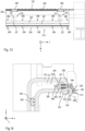
- 4 and 5 show sectional views in the closed state of the holding device 113, wherein the section of 4 in the xz plane centrally through the left bending tool 109 3 runs, whereas the cut of the figure 5 in the xz plane centrally through the extreme left wedge 117 3 runs. how to get out 4 and
- the contact element 117 is attached to the cross brace 118 by means of fasteners in the form of screws 120 .
- the contact element 117 has a wedge-shaped tip, which is moved into the holding device 113 in order to open it, as will be described in more detail further below.
- the holding device 113 comprises the clamping plate 114, which is formed from a front section 114a and a rear section 114b which are firmly connected to one another, e.g. via a screw connection.
- the rear section 114b is arranged in a recess at the lower end of the upper beam 105 and is held there together with the front section 114a via the fastening means 115 already mentioned above on the upper beam 105.
- the fastening means 115 is a screw which extends from an opening in the front section 114a of the clamping plate 114 through a bore in the rear section 114b of the clamping plate 114 into a threaded bore in the upper beam 105 .
- the screw comprises a rear threaded section 115b, which is screwed to the upper beam 105, and a cylindrical section 115a, on which an elastic means 121 is arranged, which is formed from plate fields in the embodiment described here. Furthermore, the fastening means 115 has a head 115c which presses against the elastic means 121 so that a biasing force is generated. This biasing force presses the rear section 114b of the clamping plate 114 against the bending tool 109, which is accommodated in a gap between the upper beam 105 and the rear section 114b. As a result, the bending tool 109 is fixed in the holding device 113 .
- the correct positioning of the bending tool 109 in the holding device 113 is achieved with the aid of a positioning means 123 in the form of an adjusting wedge, the triangular tip of which engages in a corresponding depression 125 in the bending tool 109 .
- a positioning means 123 in the form of an adjusting wedge, the triangular tip of which engages in a corresponding depression 125 in the bending tool 109 .
- this adjusting wedge slides into the depression 125 and thus ensures that the bending tool 109 is correctly arranged on the upper beam 105 .
- an anti-loss device 122 in the form of a tongue or groove, into which an undercut 124 of the bending tool 109 engages.
- the engagement of the loss prevention device 122 in the undercut 124 ensures that the bending tool 109 gets caught on the upper beam 105.
- the bending tool 109 can then be removed from the upper beam 105 manually by an operator via a corresponding tilting movement.
- a respective pocket 129 is formed between the front section 114a and the rear section 114b of the clamping plate.
- a contact block 126 with a beveled contact surface 128 is inserted in the area of this pocket.
- the contact surface 128 comes into contact with the contact element 117 .
- an inclined contact surface 127 for the contact element 117 is provided on the front section 114a.
- the contact element 117 is inserted from above as part of the opening of the holding device 113, wherein in the state of 4 and 5 the contact element 117 has not yet been inserted so deeply that the holding device is open.
- FIG. 6 shows a sectional view analogous to 4 with the holding device 113 open 7 a sectional view analogous to figure 5 when the holding device 113 is open.
- the upper beam 105 is compared to 4 and 5 move a little further up, so that the contact elements 117 compared to 4 and 5 penetrate deeper into the corresponding pockets 129.
- the clamping plate 114 is moved to the right, whereby the elastic means 121 is compressed and thereby the clamping force acting on the bending tool 109 is released.
- the release means thus generates a release force acting against the clamping force.
- FIG. 8 a second embodiment of a bending machine according to the invention is described.
- This bending machine is in the perspective view of 8 denoted by reference numeral 200.
- This is a so-called panel bender, which is used to bend metal sheets in the same way as press brakes, but unlike press brakes, the metal sheets are fixed during the bending process.
- the panel bender 200 comprises a machine body 201, which has two side stands 202 and 203, among other things.
- An upper hold-down device 230 movable in the height direction and a stationary lower hold-down device 232 extend between the side stands.
- a hold-down tool 231 is provided at the lower end of the upper hold-down device 230 .
- a hold-down tool 233 is provided at the upper end of the lower hold-down device 232 .
- the upper hold-down device 230 moves downwards so that the workpiece is clamped between the hold-down devices 231 and 233 .
- the movement of the upper hold-down device 230 is preferably effected via hydraulics, which cannot be seen from the figures.
- a primary bending beam 234 and two secondary bending beams 205, 205' are provided in the panel bender 200 for bending the sheet metal fixed between the hold-down tools 231 and 233.
- a respective secondary bending beam represents a bending beam within the meaning of the patent claims.
- the primary bending beam 234 extends along the hold-down devices 230 and 232 in the width direction (i.e. the y-direction) of the panel bender.
- An upper bending tool 235 and a lower bending tool 236 are permanently attached to the primary bending beam, i.e. these bending tools cannot be exchanged without additional tools.
- the primary bending beam 234 can be moved in the z-direction and the x-direction and can thereby use the bending tools 235 and 236 to bend the sheet metal that is fixed between the hold-down tools 231 and 233 .
- the two secondary bending beams 205, 205' are used in the panel bender 200. These bending beams are arranged on the primary bending beam 234 and follow the movement of the primary bending beam in the x and z directions. In addition, the secondary bending beams 205, 205' can be moved in the y-direction relative to the primary bending beam 234. Corresponding extension sections 237 and 237′ in the form of profiles are attached on each side of the primary bending beam 234, with the secondary bending beam 205 being able to be moved into the extension section 237 and the secondary bending beam 205′ being able to be moved into the extension section 237′ can be.
- the secondary bending cheeks 205, 205' are also located in the extension sections 237, 237'.
- the movement of the secondary bending beams 205, 205' relative to the primary bending beam 234 is effected via belt drives which include rotary drives 240, 240', deflection rollers 241, 241' and toothed belts 238, 238'.
- the structure of the belt drives is explained further below with the help of 9 explained in more detail.
- corresponding bending tools are attached to the secondary bending beams 205, 205' in an exchangeable manner. Examples are in 8 two bending tools 209 are shown, which are held on the secondary bending beam 205 or on the secondary bending beam 205' via holding devices 213, which are described below.
- the secondary bending beam 205 or 205' can be moved into the primary bending beam 234 by the extension sections 237 or 237'. The movement of the primary bending beam 234 can then cause the corresponding secondary bending beam to also move and the bending tools 209 to interact with the metal sheet. After completion of the bending process, the secondary bending beam used is moved back into the extension section 237 or 237'.
- a release means 216 interacts (see 10 ) with the fixture 213, thereby releasing the bending tools 209 from the fixture 213, as will be described in more detail below.
- FIG. 9 shows the structure of the primary bending beam 234 and the secondary bending beams 205, 205' in a plan view from the front.
- the upper rotary drive 240 is used, which drives the toothed belt 238, which is deflected via the deflection roller 241 and guided back to the rotary drive 240.
- the secondary bending beam 205 is connected to the toothed belt 238, so that the movement of the toothed belt causes the movement of the secondary bending beam in the y-direction via the rotary drive 240.
- the lower rotary drive 240' is provided for moving the secondary bending beam 205', which is deflected back to the rotary drive 240' via the deflection roller 241'.
- the toothed belt 238' is connected to the secondary bending beam 205', so that the movement of the toothed belt leads to the movement of the secondary bending beam 205' in the y-direction.
- two guide rails 250 are provided, which extend over the length of the primary bending beam 234 and the two extension sections 237, 237'.
- FIG. 10 shows a perspective detailed view of the area of the left secondary bending beam 205 8 .
- the secondary bending beam 205 has a U-shape Profile incorporated into a corresponding U-shaped profile of extension portion 237.
- the secondary bending beam 205 is driven by two upper and two lower guide carriages 249 (see Figures 11 to 14 ) slidably guided along the guide rails 250.
- two holding devices 213 an upper and a lower holding device
- each of which includes a front clamping strip 243 via which bending tools are clamped to the secondary bending beam 205.
- the release means 216 which is not visible per se and which opens the corresponding holding device, is shown with dashed lines for both holding devices 213.
- the release means for the upper holding device comprises two contact elements 217 in the form of wedges which are fastened and in particular screwed to the underside of the upper leg of the extension section 237 .
- a wedge strip 242 is provided, which is movably arranged between the upper leg of the extension section 237 and the upper leg of the bending beam 205. The wedge bar 242 interacts with the contact elements 217, as will be described further below.
- Corresponding contact elements 217 in the form of wedges are also provided on the upper side of the lower leg of the extension section 237, which in turn interact with a wedge strip 242, which is movably arranged between the lower leg of the extension section 237 and the lower leg of the bending cheek 205.
- 11 and 12 show in detail the structure of the upper holding device 213 and the associated release means 216 of the bending beam 205 in a state in which the bending tool 209 is fixed by the holding device 213.
- 11 is a plan view from above to see a level in which the two contact elements 217 and the wedge strip 242 for the upper holding device are located.
- the secondary bending beam 205 is in a position that is outside of the primary bending beam 234, but not yet in one 11 corresponds to the release position further to the left, in which the holding device 213 is open. how to get out
- V-ledgee 242 has two sloping contact surfaces 227 in the position of 11 do not yet interact with opposite inclined surfaces of the contact elements 217.
- FIG. 12 shows a section in the xz plane 11 at the position of the bending tool 209.
- the fastening means 244 is screwed to a holding means 245 in the form of a cylindrical pin, with the holding means 245 in turn being inserted in a bore of the V-ledge 242 and thereby creating a rigid connection via the further fastening means 246 between the V-ledge 242 and the holding means 245 is produced.
- the holding means 245 holds the V-ledge 242 between the upper leg of the extension section 237 and the lower leg of the bending beam 205.
- the rear clamping strip 247 is located behind the front clamping strip 243, which is firmly connected to the upper leg of the bending beam 205, for example via a screw connection.
- the rear clamping strip 247 has a bore in which there is a socket 248 through which the holding means 248 extends.
- the socket and a portion on the back of the rear terminal block 247 press against the elastic means 221 in the form of disc springs.
- a section of the elastic means 221 is arranged in a seat of the clamping bar 242, so that the clamping bar 242 constitutes an abutment for the elastic means 221, which is placed under pretension.
- the distance between the front clamping strip 243 and the rear clamping strip 242 is in 12 so small that the bending tool 209 is clamped between the two clamping strips.
- a positioning means 223 in the form of an adjusting wedge is again provided, which engages in a corresponding depression 225 of the bending tool 209 .
- a captive 222 in the form of a Tongue or groove provided, in which an undercut 224 of the bending tool 209 engages.
- the secondary bending beam 205 is moved further to the left in the y-direction until it reaches the in 13 and 14 shown release position reached.
- 13 shows a plan view analogous to 11 and 14 a cut analogous to 12 . how to get out 13 recognizes, upon reaching the release position, the front oblique section of the corresponding contact elements 217 interacts with the opposite oblique contact surfaces 227 of the wedge strip 242.
- the wedge strip 242 slides forward together with the holding means 245 and the front clamping strip 243 ( ie in the sectional view of 14 to the right), whereby the distance between the front clamping strip 243 and the rear clamping strip 247 increases and the clamping of the bending tool 209 in the holding device 213 is thereby released.
- the bending tool 209 is still held in the holding device via the loss prevention device 222, but can be removed from the holding device by an operator via a corresponding tilting movement.
- Embodiments of a bending machine have been described above, in which the fixing of the bending tools in a corresponding holding device is ensured via an elastic means and this fixing is released purely mechanically by generating a corresponding release force. Nevertheless, it is also possible for the bending tools to be fixed in some other way, e.g. hydraulically, and for the corresponding release force to release the fixing also to be generated hydraulically.
- hydraulic clamping is used instead of mechanical clamping in the panel bender described above, this has the disadvantage that hydraulic hoses, for example via energy chains, have to be routed over the entire bending length.
- a hydraulic terminal block with a closed hydraulic circuit can be used.
- the secondary bending beam has two positions, a parking position and a tool change position. The bending tool is still clamped in the parking position, whereas this clamping is released in the tool change position. In the tool change position, a quick-release coupling of the otherwise self-sufficient hydraulic circuit of the clamp is connected to a controlled circuit and the pressure of the clamp for disengaging or clamping the bending tools is controlled directly.
- a hydraulic pump can be provided for this purpose.
- the hydraulic pressure in the self-sufficient hydraulic circuit is constant and the bending tools are held in the clamping unit. There is no connection to the controlled hydraulic circuit. If the secondary folding beam is moved to the tool change position, it is coupled to the controllable hydraulic circuit via the quick coupling. The hydraulic pressure in the controlled hydraulic circuit can then be reduced to thereby effect release of the clamp. On the other hand, the pressure for effecting the clamping is increased again. If the secondary folding beam is then moved from the tool change position to the parking position after a tool change, the controllable hydraulic circuit is decoupled again, with a non-return valve keeping the pressure within the clamp constant. The clamping is then self-sufficient again.
- an already existing movement of a bending beam in a bending machine is also used in a simple manner to open a holding device in order to thereby release bending tools fixed in the holding device.
- a release position for the movable bending beam is defined, with a movement of the bending beam towards the release position actuating a corresponding release means when the release position is reached, in order to thereby open the holding device.
- the invention is applicable to various types of Bending machines can be used. In particular, it can be used both in press brakes for free bending of workpieces and in panel benders, where the workpiece is fixed during the bending process.
Landscapes
- Engineering & Computer Science (AREA)
- Mechanical Engineering (AREA)
- Bending Of Plates, Rods, And Pipes (AREA)
Priority Applications (4)
| Application Number | Priority Date | Filing Date | Title |
|---|---|---|---|
| EP21208406.5A EP4180140A1 (fr) | 2021-11-16 | 2021-11-16 | Machine à plier |
| PCT/EP2022/081558 WO2023088790A1 (fr) | 2021-11-16 | 2022-11-10 | Machine à cintrer |
| CN202280075730.0A CN118234576A (zh) | 2021-11-16 | 2022-11-10 | 折弯机 |
| EP22817898.4A EP4433236A1 (fr) | 2021-11-16 | 2022-11-10 | Machine à cintrer |
Applications Claiming Priority (1)
| Application Number | Priority Date | Filing Date | Title |
|---|---|---|---|
| EP21208406.5A EP4180140A1 (fr) | 2021-11-16 | 2021-11-16 | Machine à plier |
Publications (1)
| Publication Number | Publication Date |
|---|---|
| EP4180140A1 true EP4180140A1 (fr) | 2023-05-17 |
Family
ID=78649236
Family Applications (2)
| Application Number | Title | Priority Date | Filing Date |
|---|---|---|---|
| EP21208406.5A Withdrawn EP4180140A1 (fr) | 2021-11-16 | 2021-11-16 | Machine à plier |
| EP22817898.4A Pending EP4433236A1 (fr) | 2021-11-16 | 2022-11-10 | Machine à cintrer |
Family Applications After (1)
| Application Number | Title | Priority Date | Filing Date |
|---|---|---|---|
| EP22817898.4A Pending EP4433236A1 (fr) | 2021-11-16 | 2022-11-10 | Machine à cintrer |
Country Status (3)
| Country | Link |
|---|---|
| EP (2) | EP4180140A1 (fr) |
| CN (1) | CN118234576A (fr) |
| WO (1) | WO2023088790A1 (fr) |
Citations (8)
| Publication number | Priority date | Publication date | Assignee | Title |
|---|---|---|---|---|
| DE3026847A1 (de) | 1979-08-01 | 1981-02-05 | Haemmerle Ag | Spannvorrichtung zur befestigung eines werkzeuges an einem werkzeughalter |
| JPS57199523A (en) * | 1982-05-28 | 1982-12-07 | Hitachi Ltd | Bending die holding device |
| DE19513576A1 (de) | 1995-04-19 | 1996-10-31 | Guenzburger Werkzeugmaschinenf | Klemmvorrichtung für das lösbare Befestigen eines Werkzeuges in einer Biegepresse |
| US6782729B2 (en) * | 2000-08-14 | 2004-08-31 | Trumpf Maschinen Austria Gmbh & Co. Kg. | Tool clamping device for shaping tool, especially for a press brake |
| US20080040864A1 (en) * | 2006-06-01 | 2008-02-21 | Wila B.V. | Automatic safety click |
| US20110247389A1 (en) * | 2008-11-11 | 2011-10-13 | Wila B.V. | Device for Clamping a Tool |
| WO2015164483A1 (fr) | 2014-04-26 | 2015-10-29 | Wilson Tool International Inc. | Pince dynamique et porte-outil correspondants |
| WO2020225761A1 (fr) * | 2019-05-08 | 2020-11-12 | Salvagnini Italia S.P.A. | Machine à plier des feuilles métalliques |
-
2021
- 2021-11-16 EP EP21208406.5A patent/EP4180140A1/fr not_active Withdrawn
-
2022
- 2022-11-10 WO PCT/EP2022/081558 patent/WO2023088790A1/fr active Application Filing
- 2022-11-10 EP EP22817898.4A patent/EP4433236A1/fr active Pending
- 2022-11-10 CN CN202280075730.0A patent/CN118234576A/zh active Pending
Patent Citations (8)
| Publication number | Priority date | Publication date | Assignee | Title |
|---|---|---|---|---|
| DE3026847A1 (de) | 1979-08-01 | 1981-02-05 | Haemmerle Ag | Spannvorrichtung zur befestigung eines werkzeuges an einem werkzeughalter |
| JPS57199523A (en) * | 1982-05-28 | 1982-12-07 | Hitachi Ltd | Bending die holding device |
| DE19513576A1 (de) | 1995-04-19 | 1996-10-31 | Guenzburger Werkzeugmaschinenf | Klemmvorrichtung für das lösbare Befestigen eines Werkzeuges in einer Biegepresse |
| US6782729B2 (en) * | 2000-08-14 | 2004-08-31 | Trumpf Maschinen Austria Gmbh & Co. Kg. | Tool clamping device for shaping tool, especially for a press brake |
| US20080040864A1 (en) * | 2006-06-01 | 2008-02-21 | Wila B.V. | Automatic safety click |
| US20110247389A1 (en) * | 2008-11-11 | 2011-10-13 | Wila B.V. | Device for Clamping a Tool |
| WO2015164483A1 (fr) | 2014-04-26 | 2015-10-29 | Wilson Tool International Inc. | Pince dynamique et porte-outil correspondants |
| WO2020225761A1 (fr) * | 2019-05-08 | 2020-11-12 | Salvagnini Italia S.P.A. | Machine à plier des feuilles métalliques |
Also Published As
| Publication number | Publication date |
|---|---|
| WO2023088790A1 (fr) | 2023-05-25 |
| EP4433236A1 (fr) | 2024-09-25 |
| CN118234576A (zh) | 2024-06-21 |
Similar Documents
| Publication | Publication Date | Title |
|---|---|---|
| DE69609468T2 (de) | Befestigungsvorrichtung des oberen Werkzeuges einer Biegepresse | |
| EP1893365B1 (fr) | Dispositif de fixation d'outil pour dispositif d'entraînement par came | |
| EP2881188B1 (fr) | Unité de butée arrière pour cintreuse | |
| EP0274710B1 (fr) | Pince motorisée portable pour le serrage de cavaliers ou similaires | |
| EP2049282A1 (fr) | Entraînement par courroie trapézoïdale comprenant un dispositif de rappel forcé | |
| WO2002030659A1 (fr) | Transmission par courroie trapezoidale | |
| EP1824641B1 (fr) | Element de serrage de pieces, notamment un etau | |
| EP3569354B1 (fr) | Dispositif de fixation de pièces à usiner et installation d'usinage | |
| DE102010028678B4 (de) | Werkzeughalterung, Werkzeugmaschine mit einer derartigen Werkzeughalterung sowie Verfahren zum Festlegen eines Bearbeitungswerkzeuges an einer Werkzeughalterung einer Werkzeugmaschine | |
| DE60118296T2 (de) | Gesimsbiegemaschine mit pneumatischem Steuersystem zum Schnellspannen von Gesimsbiegewerkzeugen | |
| DE102011017425B9 (de) | Spannvorrichtung zum Spannen von Werkstücken | |
| AT510840B1 (de) | Fertigungsanlage mit hilfsvorrichtung zur zwischenpositionierung von werkstücken | |
| DE10223894B4 (de) | Plattenklemmvorrichtung | |
| EP4180140A1 (fr) | Machine à plier | |
| DE69702326T2 (de) | Vorrichtung zur Bewegung der Walzen in einem Vierwalzengerüst zum Walzen von Blech | |
| DE19858837B4 (de) | Presse zum Innenhochdruckumformen | |
| DE60223987T2 (de) | Stanzmaschine | |
| WO2020212055A1 (fr) | Tête de pose, fiche de presse ou dispositif de pose pourvu de cette tête de pose et procédé d'assemblage d'un élément d'assemblage pourvu de la tête de pose | |
| DE102005018866B3 (de) | Vorrichtung und Verfahren zum Biegen oder Abkanten eines Gegenstands, insbesondere eines Blechteils | |
| EP3569353A1 (fr) | Dispositif de commande | |
| DE10008489B4 (de) | Verfahren und Vorrichtung zur Zuführung einer Druckplatte | |
| EP1377395B1 (fr) | Machine de pliage, en particulier presse a estamper ou a plier, pourvue d'un outil inferieur reglable | |
| AT524261B1 (de) | Biegevorrichtung mit Hinteranschlageinheit | |
| DE3021332A1 (de) | Vorrichtung zum verbinden wneigstens zweier bauteile durch ein schnitt-umform-verfahren | |
| EP4212758A1 (fr) | Appareil de fixation et procédé de fixation d'un connecteur de courroie à une extrémité d'une courroie de transport |
Legal Events
| Date | Code | Title | Description |
|---|---|---|---|
| PUAI | Public reference made under article 153(3) epc to a published international application that has entered the european phase |
Free format text: ORIGINAL CODE: 0009012 |
|
| STAA | Information on the status of an ep patent application or granted ep patent |
Free format text: STATUS: THE APPLICATION HAS BEEN PUBLISHED |
|
| AK | Designated contracting states |
Kind code of ref document: A1 Designated state(s): AL AT BE BG CH CY CZ DE DK EE ES FI FR GB GR HR HU IE IS IT LI LT LU LV MC MK MT NL NO PL PT RO RS SE SI SK SM TR |
|
| STAA | Information on the status of an ep patent application or granted ep patent |
Free format text: STATUS: THE APPLICATION IS DEEMED TO BE WITHDRAWN |
|
| 18D | Application deemed to be withdrawn |
Effective date: 20231118 |