EP4179147B1 - Anfangs- und endverfahren zum verlegen von langen schienen - Google Patents
Anfangs- und endverfahren zum verlegen von langen schienen Download PDFInfo
- Publication number
- EP4179147B1 EP4179147B1 EP21735569.2A EP21735569A EP4179147B1 EP 4179147 B1 EP4179147 B1 EP 4179147B1 EP 21735569 A EP21735569 A EP 21735569A EP 4179147 B1 EP4179147 B1 EP 4179147B1
- Authority
- EP
- European Patent Office
- Prior art keywords
- rail
- rails
- old
- laying
- new long
- Prior art date
- Legal status (The legal status is an assumption and is not a legal conclusion. Google has not performed a legal analysis and makes no representation as to the accuracy of the status listed.)
- Active
Links
Images


Classifications
-
- E—FIXED CONSTRUCTIONS
- E01—CONSTRUCTION OF ROADS, RAILWAYS, OR BRIDGES
- E01B—PERMANENT WAY; PERMANENT-WAY TOOLS; MACHINES FOR MAKING RAILWAYS OF ALL KINDS
- E01B29/00—Laying, rebuilding, or taking-up tracks; Tools or machines therefor
- E01B29/16—Transporting, laying, removing, or replacing rails; Moving rails placed on sleepers in the track
- E01B29/17—Lengths of rails assembled into strings, e.g. welded together
-
- B—PERFORMING OPERATIONS; TRANSPORTING
- B61—RAILWAYS
- B61L—GUIDING RAILWAY TRAFFIC; ENSURING THE SAFETY OF RAILWAY TRAFFIC
- B61L27/00—Central railway traffic control systems; Trackside control; Communication systems specially adapted therefor
- B61L27/10—Operations, e.g. scheduling or time tables
- B61L27/16—Trackside optimisation of vehicle or train operation
-
- E—FIXED CONSTRUCTIONS
- E01—CONSTRUCTION OF ROADS, RAILWAYS, OR BRIDGES
- E01B—PERMANENT WAY; PERMANENT-WAY TOOLS; MACHINES FOR MAKING RAILWAYS OF ALL KINDS
- E01B11/00—Rail joints
- E01B11/02—Dismountable rail joints
- E01B11/16—Fishplates for joining rails of different sections
-
- E—FIXED CONSTRUCTIONS
- E01—CONSTRUCTION OF ROADS, RAILWAYS, OR BRIDGES
- E01B—PERMANENT WAY; PERMANENT-WAY TOOLS; MACHINES FOR MAKING RAILWAYS OF ALL KINDS
- E01B11/00—Rail joints
- E01B11/54—Electrically-insulating rail joints
-
- E—FIXED CONSTRUCTIONS
- E01—CONSTRUCTION OF ROADS, RAILWAYS, OR BRIDGES
- E01B—PERMANENT WAY; PERMANENT-WAY TOOLS; MACHINES FOR MAKING RAILWAYS OF ALL KINDS
- E01B29/00—Laying, rebuilding, or taking-up tracks; Tools or machines therefor
- E01B29/02—Transporting, laying, removing, or renewing lengths of assembled track, assembled switches, or assembled crossings
-
- E—FIXED CONSTRUCTIONS
- E01—CONSTRUCTION OF ROADS, RAILWAYS, OR BRIDGES
- E01B—PERMANENT WAY; PERMANENT-WAY TOOLS; MACHINES FOR MAKING RAILWAYS OF ALL KINDS
- E01B29/00—Laying, rebuilding, or taking-up tracks; Tools or machines therefor
- E01B29/16—Transporting, laying, removing, or replacing rails; Moving rails placed on sleepers in the track
-
- E—FIXED CONSTRUCTIONS
- E01—CONSTRUCTION OF ROADS, RAILWAYS, OR BRIDGES
- E01B—PERMANENT WAY; PERMANENT-WAY TOOLS; MACHINES FOR MAKING RAILWAYS OF ALL KINDS
- E01B29/00—Laying, rebuilding, or taking-up tracks; Tools or machines therefor
- E01B29/32—Installing or removing track components, not covered by the preceding groups, e.g. sole-plates, rail anchors
-
- E—FIXED CONSTRUCTIONS
- E01—CONSTRUCTION OF ROADS, RAILWAYS, OR BRIDGES
- E01B—PERMANENT WAY; PERMANENT-WAY TOOLS; MACHINES FOR MAKING RAILWAYS OF ALL KINDS
- E01B29/00—Laying, rebuilding, or taking-up tracks; Tools or machines therefor
- E01B29/42—Undetachably joining or fastening track components in or on the track, e.g. by welding, by gluing; Pre-assembling track components by gluing; Sealing joints with filling components
- E01B29/46—Devices for holding, positioning, or urging together the rail ends
-
- E—FIXED CONSTRUCTIONS
- E01—CONSTRUCTION OF ROADS, RAILWAYS, OR BRIDGES
- E01B—PERMANENT WAY; PERMANENT-WAY TOOLS; MACHINES FOR MAKING RAILWAYS OF ALL KINDS
- E01B2201/00—Fastening or restraining methods
- E01B2201/02—Fastening or restraining methods by wedging action
Definitions
- the invention relates, in general, to the technical field of work trains such as construction and renewal trains consisting of installing equipment necessary for the construction of railway tracks or, in the case of renewal, replacing all or part of the materials constituting the tracks, namely the rails and the fixed structure such as the sleepers, as well as the ballast which ensures the holding of the track on its platform, when these materials are degraded.
- work trains such as construction and renewal trains consisting of installing equipment necessary for the construction of railway tracks or, in the case of renewal, replacing all or part of the materials constituting the tracks, namely the rails and the fixed structure such as the sleepers, as well as the ballast which ensures the holding of the track on its platform, when these materials are degraded.
- the invention relates more specifically to an initial method of laying long new rails of a railway track by a works train, a final method of laying, and a method of renewing old rails, already laid, of a railway track by long new rails initiated and/or finalized by these initial and/or final methods of laying long new rails.
- a typical complete track renewal operation uses specialized railway convoys comprising machines capable of carrying out the following operations in sequence: stripping, screening of ballast and evacuation of stripping products, by conveyor belts on wagons intended for discharge or by direct jet to the embankment, renewal of the track to be renewed (rails and sleepers), ballasting and lifting of the track, levelling and straightening, welding of rails, release of constraints, new levelling-straightening, adjustment of benches and cleaning of shoulders.
- the rail ends up elongating: since it cannot elongate lengthwise, it does so in the lateral direction, thus creating a deformation of the geometry of the track frame. Such deformations of the track are obviously extremely dangerous.
- neutralization makes it possible to fix the rails at a given state of expansion, either at a determined average temperature (for example 25°C) when the neutralization takes place by heating the rails, or with a stretching of the rails corresponding to their expansion at this average temperature when the neutralization operation is carried out by stretching the rails.
- a determined average temperature for example 25°C
- the invention aims to remedy all or part of the drawbacks of the state of the art by proposing in particular a solution making it possible to implement a method of renewing old rails with long new rails, offering the shortest possible immobilization of the railway track to reduce the duration of the work, while guaranteeing good safety of the railway track laid, in particular at the ends of the old rails framing a portion of the track to be renewed, corresponding to the ends of the new rails connected to the old railway track.
- Long rails are rails also called “long welded rails” (“LRS”) or “long bars”. These long welded rails are formed from one or a plurality of elementary rails of normal length, or “normal bars”, welded together, generally in welding workshops far from the construction site, and thus forming a single continuous unit. The distinction between long welded rails and rails made of normal bars is then very clear in terms of length, with long welded rails being able to extend over several hundred meters or even kilometers.
- the railway track here concerns both tracks laid on ballast, or tracks without ballast laid on other supports (tracks on concrete, tracks on slabs, etc.).
- the fixed structure of the railway track can vary depending on the type of track and may include, for example, sleepers, slabs, a concrete platform, etc.
- such a method allows a connection between the old railway track and the new railway track with a level of safety guaranteed by the neutralization of the rails before their fixing equivalent to the rest of the track, in particular here at the end portion of the first long new rail.
- the initial laying method can be implemented on a row of rails of the railway track or simultaneously on the two rows of parallel rails of the railway track.
- the initial laying method comprises a step of neutralizing, preferably by heating or cooling, an end portion of the old junction rail comprising the end of the old junction rail to which the end portion of the first long new rail is to be connected.
- the neutralization heating or cooling step at the reference temperature of the end portion of the first new long rail is preceded by the neutralization step, preferably by heating or cooling, of the end portion of the old junction rail comprising the end of the old junction rail to which the end portion of the first long new rail is to be connected.
- the heating or cooling step of neutralizing the end portion of the old junction rail is carried out by thermal transfer or insulation means, which preferably comprise a source of infrared radiation for heating said end portion of the old junction rail to the reference temperature.
- a step of cutting the old junction rail is carried out to form the end of the old junction rail to be connected.
- the temporary connection device comprises at least one fishplate or rail puller.
- the temporary connection devices such as the fishplate or rail puller have the function of keeping the ends of the rails abutted, regardless of the variations in external temperatures, thus ensuring the perfect joint of the ends. Another function is to maintain the reference length of the old and new rails until the step of welding the ends.
- This temporary connection device is removed once the ends of the rails are welded, and the weld has cooled after a predetermined cooling time, generally twenty minutes.
- the permanent connection, subsequent to the temporary connection makes it possible to guarantee circulation at normal speed of a railway vehicle, while the temporary connection only allows at best circulation at reduced speed.
- said ends undergo a preparation step with a view to the permanent connection step, for example an abrasion machining step.
- the final laying method comprises a step of neutralizing, preferably by heating or cooling, an end portion of the old junction rail comprising the end of the old junction rail to which the end portion of the first long new rail is to be connected.
- the neutralization heating or cooling step at the reference temperature of the end portion of the last long new rail is followed by the neutralization step, preferably by heating or cooling, of the end portion of the old junction rail comprising the end of the old junction rail to which the end portion of the last long new rail is to be connected.
- the invention also relates to a method for renewing old rails of a railway track of the type comprising a phase during which the long new rails are laid and then fixed to a fixed structure of the railway track by a work train running in one direction of travel, the renewal method being characterized in that the phase is initiated by the initial method of laying long new rails as described above and/or is finalized by the final method of laying long new rails as described above.
- the renewal method comprises a first phase during which new long rails are unloaded along the railway track from a transport train of a work train traveling in a first direction of travel, and comprises a second phase in which the work train travels in a second direction of travel opposite to the first direction of travel, the new long rails being laid and then fixed to the fixed structure such as the sleepers of the railway track during the second phase.
- Such a renewal process can be implemented by a single work train. Furthermore, the operations carried out can be sequenced in an optimized manner. It is no longer necessary to carry out all the operations at the same time, or sequenced successively in a single direction of circulation, which would have the effect of reducing the speed of circulation on the site according to the most restrictive operation. Indeed, when the work train implements all the operations in series, only one operation requiring the immobilization of the work train is needed to limit the progress of the site on the other operations. By proceeding in such a sequenced manner in two phases, and by distributing the renewal operations both in one direction of circulation, then in the other direction of traffic, a reduction in the time of the works is observed for an equivalent length of renewed rails. Finally, it is possible to carry out all these operations during the same temporary interruption of traffic while minimizing the duration of this interruption.
- the work train comprises vehicles mounted on wheel sets, for example bogies, the neutralization step by neutralization heating or cooling being carried out in an area of the work train located upstream of the first of the wheel sets of the work train bearing on the long new rails, relative to the second direction of travel.
- the neutralization heating or cooling step is followed by a step of maintaining and/or correcting the reference temperature of the neutralized rail portion, by thermal transfer or insulation, the step of maintaining and/or correcting the reference temperature preferably being carried out in a zone of the work train located at least downstream of the first of the wheel sets bearing on the long new rails, relative to the second direction of travel.
- the thermal transfer or insulation means comprise a source of infrared radiation.
- the maintenance means can provide a correction of the neutralization, in addition to said neutralization step, so as for example to tend towards a reference state that would not have been reached during the previous neutralization step.
- the initial process is an initial phase or commitment to the stages of laying the long new rails and dismantling the old rails by the works train to begin the renewal starting from this initial configuration of a portion of railway track.
- the neutralization during the initial process of laying the end portion of the old junction rail is carried out by all or part of the means for maintaining and/or correcting the reference temperature.
- the final process is a final or clearance phase of the stages of laying the long new rails and dismantling the old rails by the works train to finalize the renewal of a section of railway track.
- the neutralization during the final process of laying the end portion of the old junction rail is carried out by all or part of the means for maintaining and/or correcting the reference state.
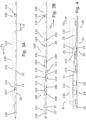
- FIGS 1, 2A, 2B, 2C and 2D illustrate diagrams of a railway convoy 10 comprising a works train 100 according to an embodiment of the invention.
- the works train 100 comprises a power car 110 at the head of the train followed, directly here, by a transport train 120 coupled to the power car 110.
- the transport train 120 is configured to ensure the transport of long new rails 22 to be transported to a works zone Z0 and preferably also to store old rails 21 to be evacuated from this same works zone Z0, as the long new rails 22 are laid.
- the work train 100 comprises a work train 130 coupled to the rear of the transport train 120.
- the work train 130 is illustrated in a variant equipped with three work vehicles 131, 132, 133 coupled successively, in particular a first work vehicle 131, a second work vehicle 132 and a third work vehicle 133. It has a variable composition, that is to say that its composition in cars can vary punctually, during a passage in the workshop for example, but which once determined, generally for a specific site, only changes during a passage in the workshop.
- old rails are understood as rails already laid, pre-existing on a track to be renewed, new rails are understood as rails replacing these rails already laid. These terms do not predict the wear or age of the rail as such.
- the railway convoy 10 comprises a welding machine 140 which is here a railway machine that can be removably coupled to the tail of the work train 100, in particular here to the tail of the work train 130, relative to a first direction of travel F1. Such a coupling makes it possible to move a railway convoy to the work zone Z0.
- the welding machine 140 is designed to be uncoupled from the work train 100 once it has arrived near the work zone Z0, as illustrated on the figure 1 , so as to be able to circulate independently of the work train 100, preferably at a distance from the work train 100. Its usefulness will be better understood by reading the renewal method described below.
- the works train 100 moves on the railway track 20 in two phases, outward A and return B , during which it implements different steps, the combination of these two phases A and B making it possible to ensure the renewal of the railway track 20.
- the new long rails 22 are unloaded successively along the railway track 20 from the transport train 120 of the work train 100, this as the work train advances in the first direction of travel F1, pulled by the motor car 110.
- the motor car 110 can optionally provide traction assistance or not to the work train 100 which is equipped with its own advance system, in particular by distributed drive wheel sets.
- the transport to the construction site can be carried out in two variants: with a self-propelled machine specific to the work train, or by being towed by a locomotive. On the construction site, the self-propelled machine can also be assisted by traction provided by the locomotive.
- these long new rails 22 can be unloaded outside the railway track 20 along the old rails 21 to be renewed, or in the center of the railway track 20.
- a step of placing supports on the ground, such as roller supports is implemented prior to unloading the long new rails, preferably by one of the vehicles of the works train 130, so that the long new rails come to rest, on the ground on these roller supports and not directly on the ground or the ballast.
- the station 107' configured to ensure the laying or installation of the roller supports is located upstream of that of the unloading of the long new rails 22, with reference to this first direction of circulation F1.
- the work station 107' ensuring the installation of the roller supports is implemented by the first vehicle 131 of the work train, in front of the second vehicle 132 at which the unloading is ensured, with reference to this first direction of circulation F1.
- each of the ends of the unloaded long new rails 22 undergoes a preparation step with a view to a permanent connection step, for example welding.
- a preparation step comprises for example an abrasion machining step.
- This welding preparation step is implemented by a welding preparation station 116 carried by the welding machine 140.
- This welding machine 140 is in this example a railway machine. In particular configurations, the welding machine could also be a rail-road welding truck or a rail-road welding excavator.
- the welding machine 140 travels independently of the work train 100 and in the first direction of travel F1, behind it.
- the welding machine 140 therefore travels generally in the same direction F1 as the work train 100, at a distance d behind it, this distance being variable during the first phase A.
- the work train 100 travels at a quasi-continuous and homogeneous speed to unload the long new rails 22, with a few breaks so as to guide the long new rails 22 towards a train laying area, these breaks marking stages A3 in the progress of the worksite (see there figure 7 )
- the welding machine 140 operates at a different speed and in a sequenced manner, alternating static phases, when preparing to weld the ends of the long new rails 22, and dynamic phases where it progresses along the railway track 20 to reach a next end, and so on.
- the works train moves in a second direction of travel F2 opposite to the first direction of travel F1, thus making the reverse journey.
- the railway convoy 10 with successively, from front to back relative to the first direction of travel F1, the locomotive 110 (which is optional if it is not used as a traction aid during the worksite) then the transport train 120 and the works train 130 then travel in reverse order: the works train 130 is at the head of the works train 100, with reference to this second direction of travel F2.
- the welding machine 140 which travelled independently and at a distance behind the works train during the first phase A, travels during the second phase B still independently and at a distance from the works train 100, but this time in front of it, with reference to this second direction of travel F2.
- the old rails 21 of the portion of railway track to be renewed are dismantled by the work train 100, then preferably loaded onto the transport train 120 of the work train 100.
- the old rails 21 are cut at regular intervals as they are loaded onto the transport train 120 of the work train 100 in order to be stored in a plurality of separate sections of old rails 21.
- the transport train 120 can be used both to store the long new rails 22 and the old rails 21.
- the old rails 21 are moved along the railway track 20 from the railway track 20 itself, in particular from their location on the sleepers 23.
- the transport train 120 is provided with handling equipment 121 such as a handling gantry making it possible to ensure a number of operations such as cutting the old rails 21, or gripping the rails 21, 22, etc. Alternatively or in addition, these operations can also be carried out in whole or in part manually.
- handling equipment 121 such as a handling gantry making it possible to ensure a number of operations such as cutting the old rails 21, or gripping the rails 21, 22, etc. Alternatively or in addition, these operations can also be carried out in whole or in part manually.
- the loading path of the old rails 21 follows the reverse path to that of unloading the new rails 22. In this way the multiplication of equipment is limited, in particular on the second vehicle 132 of the works train 130.
- the welding machine 140 which therefore travels during this second phase B in front of the work train 100 and in the same direction of travel F2 as the latter, comprises welding means 115 and carries out welding operations, preferably electric welding, of the long new rails 22 end to end.
- the welding machine 140 operates at a sufficient distance from the work train 100 so as to allow the electric welding to cool before the installation of the long new rail 22. A cooling time of the order of 20 minutes for example can thus be guaranteed.
- the laying of the long new rails 22 on the sleepers 23 of the railway track 20 is carried out by the work train 100 at a laying zone Z1 located downstream of the welding machine 140.
- This laying operation consists in particular, but not exclusively, in moving the long new rails 22 arranged along the railway track 20, to install them on the sleepers 23, at the same place where the old rails 21 are previously dismantled, this dismantling taking place in a dismantling zone Z6 upstream relative to the laying zone Z1.
- the dismantling of the old rails 21 and the laying of the long new rails 22 are carried out in parallel and therefore progress in a synchronized manner.
- the same vehicle 132 of the works train 130 mainly implements the dismantling and laying steps so that the laying zones Z1 and dismantling zones Z6 are located opposite the same vehicle 132 of the works train 130, these steps being implemented by the same second vehicle 132.
- the discontinuity of the railway track 20 caused by the dismantling of the old rails 21 and the laying of the long new rails 22 is spanned by the same vehicle 132 carried by a wheel set such as a bogie 101 upstream relative to the second direction of travel F2, running on old rails 21 and a wheel set such as a bogie 101 downstream running on long new rails 22 positioned on the sleepers 23.
- This bogie 101 downstream of the vehicle 132 implementing these two steps constitutes the first of the bogies 101 of the work train 100 on the new long rails 22, in relation to the second direction of travel F2.
- a step of neutralization by portions 24 of the long new rails 22 by heating or cooling to a reference temperature is implemented to allow fixing of the rails at a given expansion reference state.
- each of the portions 24 of the long new rails 22 is heated or cooled to the reference temperature by main neutralization means 111 located in the same zone Z2 before being laid on the sleepers 23 of the railway track 20.
- the main neutralization means 111 preferably comprise a heater such as induction heating.
- the main neutralization means 111 comprise cooling means, for example equipment for projecting a liquid flow such as water or a gas flow, ideally air, possibly compressed, dry ice, etc.
- This neutralization zone Z2 is located upstream of the first of the wheel sets, in particular here the bogies, 101 of the work train 100 carrying the long new rails 22, relative to the second direction of circulation F2.
- the neutralization heating or cooling step is followed by a step of maintaining and/or correcting the reference temperature of the neutralized rail portion 24 , by thermal transfer or insulation.
- the thermal transfer or insulation means comprise a source of infrared radiation.
- This step of maintaining and/or correcting the reference temperature is carried out in a zone Z3 of the work train 100 located at least downstream of the neutralization zone Z2 and downstream of the first of the bogies 101 bearing on the long new rails 22, relative to the second direction of travel F2.
- This zone Z3 continues downstream of the second bogie bearing on the new rails in a variant illustrated in FIG. figure 4 .
- the new long rails 22 are then fixed to the sleepers 23 by fasteners in a zone Z4 of the work train 100 located directly downstream of the zone Z3 of the work train in which the step of maintaining and/or correcting the reference temperature is carried out.
- This step of maintaining and/or correcting of the reference state, namely the reference temperature is implemented by at least means of maintaining and/or correcting 113 the reference temperature located at the level of this same zone Z3.
- an additional step of maintaining and/or correcting the reference temperature of the portion of rail 24 neutralized by thermal transfer or insulation can be implemented on another zone Z5 of maintaining and/or correcting the upstream reference temperature, for example by additional means of maintaining and/or correcting 112 the reference temperature, upstream of the first of the bogies 101 bearing on the long new rails 22, and downstream of the neutralization zone Z2 (see the figure 4 ).
- a significant distance separates the main neutralization means 111 from the first of the bogies 101 bearing on the long new rails 22, approximately 8m in this embodiment, which justifies the interest of such an additional device for maintaining and/or correcting 112 the upstream reference temperature.
- complementary means for maintaining the reference temperature may be used, such as complementary means for maintaining and/or correcting 114 the reference temperature which are located between the means 113 and 112, at the level of the first and second of the bogies 101 bearing on the long new rails 22 : the first of the bogies 101 bearing on the long new rails 22 forming the downstream bogie of the second vehicle 132 and the second of the bogies 101 bearing on the long new rails 22 forming the upstream bogie of the first vehicle 131 which succeeds it with reference to the second direction of travel F2.
- the step of maintaining and/or correcting the reference state is implemented over the entire portion of rail located between its neutralization and its fixing, the fixing of the fasteners being directly downstream of the maintenance and/or correction to the reference state.
- care will be taken to ensure that the distance separating a zone Z4 of the work train in which the step of fixing the long new rail is carried out from the zone Z3 of the work train in at which the step of maintaining and/or correcting the reference state is carried out, is less than 7m.
- initial and final phases must be implemented to initiate and finalize the laying of the long new rails 22 at the same time as the dismantling of the old rails 21 in relation to the pre-existing railway track to which it must be connected.
- the heating or cooling of the end portion 211' of the old junction rail 211 upstream of its end 211' before cutting the rail can be ensured by at least one of the neutralization heating or cooling means 111 , and/or by all or part of the means 112, 113, 114 for maintaining and/or correcting the reference temperature.
- the neutralization heating or cooling means 111 can preferably be activated only from the step of neutralizing the end portion 221' of the first of the long new rails 221 at the reference temperature.
- the advantage of using only all or part of the means 112, 113, 114 for maintaining and/or correcting the reference temperature is that at this location, the old junction rails 211 are laid on the sleepers 23 and the use of the neutralization means 111 such as induction heating could damage the fasteners of the old rails which are, like the rails, also metallic.
- the maintenance and/or correction heating 112, 113, 114 is less powerful than the induction heating 111 and avoids damaging the fasteners. This is simpler to implement than using a means of varying the power of the neutralization means 111 , in particular induction heating, which would make the equipment more expensive and more complex.
- the heating or cooling of the end portion 211' of the old junction rail 211 is preferably carried out over a distance greater than the area over which the fasteners are dismantled (see Figure 5B ).
- a new rail is neutralized in a detached state.
- these work stations can be substantially moved.
- this car 133 which can ensure the removal of the fasteners from the rails.
- a step of collecting the fasteners is then preferably implemented directly after their removal.
- the long new rails 22 are for their part attached either with new fasteners, or with old fasteners previously removed and then collected, in order to ensure recycling of the fasteners if their condition allows it.
- a workstation is understood to mean any workstation capable of receiving people to carry out manual operations and/or any equipment intended to carry out these operations automatically or semi-automatically.
- the removal of the fasteners, and therefore the subsequent blocking of the fasteners is implemented from a downstream portion at the end 211' of the old junction rail 211 comprising the end 211' to which the end 221' of the first long new rail 221 must be connected and extends to an upstream portion at the end 212' of the old junction rail 212 comprising the end 212' to which the end 222' of the last long new rail 222 must be connected, with reference to the second direction of travel F2.
- the laying of the long new rails is done at a reference temperature, this laying being followed by operations aimed at subsequently fixing it in accordance with the predetermined reference temperature.
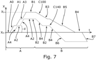
- FIG. 7 a diagram is shown illustrating the operation of the railway convoy 10, in particular its progress along the railway track 20 : the abscissa indicating the evolution of time during the work and the ordinate indicating the position relative to the railway track 20.
- a first curve C100 higher here, corresponds to the progress of the works train 100 and a second curve C140, lower than the curve C100, corresponds to the progress of the railway vehicle 140 traveling independently and at a distance d from the works train 100.
- the works train 100 moves from a starting position X0 to an arrival position X1 along the railway track 20.
- the works train 100 alternates between dynamic steps A1 , of unloading the long new rails 22 along the railway track 20, and static steps A3 , marking stages during which each long new rail is engaged in guide tunnels of the works train to ensure the proper unloading of these long new rails 22 along the railway track 20.
- the railway vehicle 140 moves in stages, alternating between static A2 stages of preparation for welding and dynamic A4 stages of movement from one end of two long new rails to another end following the first direction of travel F1.
- the second phase B continues during which the work train 100 moves from the arrival position X1 to the departure position X0 along the railway track 20.
- the work train 100 alternates between dynamic steps B3 of loading the old rails 21 onto the transport train 120 and static steps B5 marking levels during which the old rail 21 is cut during its loading so that it can be stored in a plurality of elementary sections on the transport train 120.
- the railway vehicle 140 moves in stages by alternating welding steps B2 and steps B4 of moving from one end of two long new rails to another following the second direction of travel F2.
- Steps B6 and B7 mark a movement of the welding machine 140 and the work train 100, respectively, in the continuity of its progress and beyond the starting position X0 in order to guarantee the welding between the two connected ends 212', 222' at the end of the worksite.
- the initial phases B1 ( Figures 5A to 5F ) and final B4 ( Figures 6A to 6F ) of the second phase B are indicated by steps, which is a simplification given the very low speed of movement of the work train 100 during these two phases A and B.
- such a method makes it possible to simply and relatively quickly implement the operations of electric welding of the LRS rails, the dismantling and reassembly of the rail fasteners, and the neutralization of the rails.
- the composition of the work train may be different.
- the work train may consist of only two cars as illustrated in the figures 5 And 6 or three cars as shown in the figures 1, 2 , 3 and 4 .
- the work train can be configured to work without the third work vehicle 133 of the work train 130.
- the old track fasteners can be dismantled with hand tools upstream of the railway convoy, with reference to the second direction of travel F2,
- the rails can be renewed in parallel two by two so as to renew the entire railway track during the operations, and/or successively the along one side only of the railway track so as to renew the rails of a single row.
- the initial and/or final laying processes can be implemented, as for renewal, on one row of rails of the railway track or simultaneously on the two parallel rows of rails of the railway track.
- the neutralization may be carried out otherwise than by heating or cooling, by mechanical constraints likely to cause the rail portions to stretch corresponding to their expansion at this reference temperature.
- the reference state then corresponds to a given expansion state as a reference, itself corresponding to a state of the rail portion if it were subjected to this reference temperature.
- first and second phases A and B are implemented spaced out in time: the first phase A can be implemented one night, and the second phase B can be implemented the following night.
- the old rails could also be unloaded along the railway track from their position on the sleepers.
- Bogies can also be formed by any type of wheel set.
- Such a rail convoy is particularly interesting in that it allows for the renewal of a railway track, offering the shortest possible immobilization of the railway track to reduce the duration of the construction site, while guaranteeing good safety of the railway track laid.
- the rail convoy can be used to only transport and unload the long new rails along the railway track from the transport train, either outside of the railway track, either inside, with an optional welding operation and installation of the roller supports.
Landscapes
- Engineering & Computer Science (AREA)
- Architecture (AREA)
- Civil Engineering (AREA)
- Structural Engineering (AREA)
- Mechanical Engineering (AREA)
- Machines For Laying And Maintaining Railways (AREA)
- Train Traffic Observation, Control, And Security (AREA)
- Details Of Indoor Wiring (AREA)
- Greenhouses (AREA)
- Installation Of Indoor Wiring (AREA)
Claims (9)
- Anfängliches Verfahren zum Verlegen neuer Langschienen (22) eines Gleises (20) durch einen in einer Bewegungsrichtung (F2) fahrenden Arbeitszug (100), wobei das anfängliche Verfahren bei einem derartigen Austauschverfahren für alte Schienen (21) des Gleises (20) eingesetzt wird, dass es eine Phase (B) umfasst, in der die neuen Langschienen (22) verlegt und dann auf einer festen Struktur (23) des Gleises (20) befestigt werden, wenn der Arbeitszug in Bewegungsrichtung (F2) fährt, wobei das anfängliche Verlegungsverfahren umfasst:- einen Schritt des Verlegens eines Teils mindestens einer ersten der neuen Langschienen (221) auf der festen Struktur (23) bis zu mindestens einem Ende (211') einer alten Verbindungsschiene (211);- einen Schritt des temporären Stoßverbindens des Endes (211') der alten Verbindungsschiene (211) mit mindestens einem Ende (221') der ersten neuen Langschiene (221) durch mindestens eine temporäre Verbindungsvorrichtung (30);- einen Schritt des dauerhaften Verbindens, beispielsweise durch Schweißen, der beiden miteinander verbundenen Enden der alten Verbindungsschiene (211) und der ersten neuen Langschiene (221);- vor
dem Schritt des Verlegens, einem Schritt des Erwärmens oder Abkühlens mindestens eines Endabschnitt (221') der ersten neuen Langschiene (221) zum Neutralisieren auf die Referenztemperatur, wobei der Endabschnitt das Ende (221') der ersten neuen Langschiene (221) umfasst, mit dem das Ende (211') der alten Verbindungsschiene (211) verbunden werden soll. - Anfängliches Verfahren zum Verlegen von Schienen nach Anspruch 1, dadurch gekennzeichnet, dass es einen Schritt des Neutralisierens, vorzugsweise durch Erwärmen oder Abkühlen, eines Endabschnitts der alten Verbindungsschiene (211) umfasst, der das Ende (211') der alten Verbindungsschiene (211) umfasst, mit dem der Endabschnitt (221') der ersten neuen Langschiene verbunden werden soll.
- Anfängliches Verfahren zum Verlegen von Schienen nach Anspruch 1 oder 2, dadurch gekennzeichnet, dass der Schritt des Erwärmens oder Abkühlens zum Neutralisieren des Endabschnitts der alten Verbindungsschiene durch Wärmeübertragung oder -isolierung durchgeführt wird, vorzugsweise umfassend eine Infrarotstrahlungsquelle zum Erwärmen des Endabschnitts der alten Verbindungsschiene auf die Referenztemperatur.
- Anfängliches Verfahren zum Verlegen von Schienen nach einem der vorangehenden Ansprüche, dadurch gekennzeichnet, dass vor dem Schritt des temporären Stoßverbindens des Endes (211') der alten Verbindungsschiene (211) mit dem Ende (221') der ersten neuen Langschiene (221) durch die temporäre Verbindungsvorrichtung (30) ein Schritt des Schneidens der alten Verbindungsschiene (211) durchgeführt wird, um das Ende (211') der alten zu verbindenden Verbindungsschiene (211) zu formen.
- Anfängliches Verfahren zum Verlegen von Schienen nach einem der vorhergehenden Ansprüche, dadurch gekennzeichnet, dass die temporäre Verbindungseinrichtung (30) mindestens eine Lasche oder einen Schienenzieher umfasst.
- Anfängliches Verfahren zum Verlegen von Schienen nach einem der vorhergehenden Ansprüche, dadurch gekennzeichnet, dass an den Enden (211', 221') vor oder nach dem Schritt des temporären Stoßverbindens des Endes (211') der alten Verbindungsschiene (211) mit dem Ende (221') der ersten neuen Langschiene (221) durch die temporäre Verbindungsvorrichtung (30) ein Vorbereitungsschritt im Hinblick auf den Schritt des dauerhaften Verbindens, beispielsweise einen Schleifbearbeitungsschritt, erfolgt.
- Abschließendes Verfahren zum Verlegen von neuen Langschienen (22) eines Gleises (20) durch einen in einer Bewegungsrichtung (F2) fahrenden Arbeitszug (100), wobei das abschließende Verfahren bei einem derartigen Austauschverfahren für alte Schienen (21) des Gleises (20) eingesetzt wird, dass es eine Phase (B) umfasst, in der die neuen Langschienen (22) verlegt und dann auf einer festen Struktur (23) des Gleises (20) befestigt werden, wenn der Arbeitszug in Bewegungsrichtung (F2) fährt, wobei das abschließende Verlegungsverfahren umfasst:- einen Schritt des Verlegens eines Teils mindestens einer letzten der neuen Langschienen (222) auf der festen Struktur (23) zu mindestens einem Ende (212') einer alten Verbindungsschiene (212);- einen Schritt des temporären Stoßverbindens eines Endes (222') der letzten neuen Langschiene (222) mit mindestens dem Ende (212') der alten Verbindungsschiene (212) durch mindestens eine temporäre Verbindungsvorrichtung (30);- einen Schritt des dauerhaften Verbindens, beispielsweise durch Schweißen, der beiden verbundenen Enden der alten Verbindungsschiene (212) und der letzten neuen Langschiene (222);- vor
dem Schritt des Verlegens, einem Schritt des Erwärmens oder Abkühlens mindestens eines Endabschnitt s(222') der letzten neuen Langschiene (222) zum Neutralisieren auf die Referenztemperatur, wobei der Endabschnitt das Ende (222') der letzten neuen Langschiene (222) umfasst, mit dem das Ende (212') der alten Verbindungsschiene (212) verbunden werden soll. - Abschließendes Verfahren nach Anspruch 7,
dadurch gekennzeichnet, dass es einen Schritt des Neutralisierens, vorzugsweise durch Erwärmen oder Abkühlen, eines Endabschnitts (212') der alten Verbindungsschiene (212) umfasst, der das Ende (212') der alten Verbindungsschiene umfasst, mit dem der Endabschnitt der letzten neuen Langschiene (222) verbunden werden soll. - Austauschverfahren für alte Schienen (21) eines Gleises (20) derartig, dass es eine Phase (B) umfasst, in der die neuen Langschienen (22) durch einen Arbeitszug (100), der in einer Bewegungsrichtung (F2) fährt, verlegt und dann auf einer festen Struktur (23) des Gleises (20) befestigt werden, wobei das Austauschverfahren dadurch gekennzeichnet ist, dass die Phase (B) durch das anfängliche Verfahren zum Verlegen langer neuer Schienen (22) nach einem der Ansprüche 1 bis 6 eingeleitet wird, und/oder durch das abschließende Verfahren zum Verlegen neuer Langschienen (22) gemäß Anspruch 7 oder 8 abgeschlossen wird.
Applications Claiming Priority (2)
| Application Number | Priority Date | Filing Date | Title |
|---|---|---|---|
| FR2007221A FR3112353B1 (fr) | 2020-07-08 | 2020-07-08 | Procédé initial et final de pause de longs rails et procédé de renouvellement associé |
| PCT/EP2021/069066 WO2022008686A1 (fr) | 2020-07-08 | 2021-07-08 | Procédés initial et final de pose de longs rails |
Publications (3)
| Publication Number | Publication Date |
|---|---|
| EP4179147A1 EP4179147A1 (de) | 2023-05-17 |
| EP4179147B1 true EP4179147B1 (de) | 2024-08-28 |
| EP4179147C0 EP4179147C0 (de) | 2024-08-28 |
Family
ID=72801686
Family Applications (1)
| Application Number | Title | Priority Date | Filing Date |
|---|---|---|---|
| EP21735569.2A Active EP4179147B1 (de) | 2020-07-08 | 2021-07-08 | Anfangs- und endverfahren zum verlegen von langen schienen |
Country Status (13)
| Country | Link |
|---|---|
| US (1) | US20230279616A1 (de) |
| EP (1) | EP4179147B1 (de) |
| JP (1) | JP7796675B2 (de) |
| KR (1) | KR20230054662A (de) |
| CN (1) | CN115956148A (de) |
| AU (1) | AU2021305404A1 (de) |
| BR (1) | BR112023000149A2 (de) |
| CA (1) | CA3183514A1 (de) |
| ES (1) | ES2992484T3 (de) |
| FR (1) | FR3112353B1 (de) |
| PL (1) | PL4179147T3 (de) |
| WO (1) | WO2022008686A1 (de) |
| ZA (1) | ZA202213680B (de) |
Families Citing this family (2)
| Publication number | Priority date | Publication date | Assignee | Title |
|---|---|---|---|---|
| CN117552275A (zh) * | 2023-11-24 | 2024-02-13 | 中铁建大桥工程局集团第五工程有限公司 | 一种无缝线路更换小半径曲线磨耗轨施工方法 |
| CN120119515A (zh) * | 2025-04-21 | 2025-06-10 | 中铁一局集团有限公司 | 一种快速跨线铺轨方法及设备 |
Family Cites Families (13)
| Publication number | Priority date | Publication date | Assignee | Title |
|---|---|---|---|---|
| AT307472B (de) * | 1967-12-29 | 1973-05-25 | Plasser Bahnbaumasch Franz | Verfahren und Vorrichtung zum kontinuerlich fortschreitenden Verlegen von insbesondere aus stumpfgeschweißten Schienen gebildeten Schienensträngen |
| DK0466651T3 (da) * | 1990-07-13 | 1996-01-02 | Scheuchzer Sa | Indretning til udskiftning af skinner i et jernbanesporanlæg |
| JP2648105B2 (ja) * | 1994-11-04 | 1997-08-27 | 鉄友工業株式会社 | 鉄道用レール交換装置およびこれを用いたレール交換方法 |
| GB9606761D0 (en) * | 1996-03-29 | 1996-06-05 | Henry Williams Darlington Limi | Insulated rail joints |
| JP3854368B2 (ja) * | 1997-06-05 | 2006-12-06 | 西日本旅客鉄道株式会社 | 鉄道用レール交換装置及びこれを用いたレールの交換方法 |
| FR2899249B1 (fr) * | 2006-04-04 | 2012-10-05 | Europ De Travaux Ferroviaires Etf | Procede et dispositif de renouvellement de rail ferroviaire en continu |
| CN101718066B (zh) * | 2009-11-23 | 2012-02-08 | 株洲新通铁路装备有限公司 | 一种无缝线路快速换轨作业车及其换轨方法 |
| CN102296495B (zh) * | 2011-05-25 | 2013-01-23 | 中铁二十局集团第四工程有限公司 | 大温差、强风沙条件下长钢轨铺设及焊接施工工艺 |
| FR2998590B1 (fr) * | 2012-11-23 | 2017-11-24 | Europeenne De Travaux Ferroviaires (Etf) | Train et procede de renouvellement de rails ferroviaires a haut rendement. |
| FR3020073B1 (fr) * | 2015-07-27 | 2017-01-13 | Matisa Materiel Ind Sa | Procede de renouvellement de voies ferrees et dispositif pour sa mise en oeuvre |
| CN106283996B (zh) * | 2016-10-17 | 2018-06-01 | 株洲时代电子技术有限公司 | 一种换轨列车作业方法 |
| CN108220549A (zh) * | 2016-12-22 | 2018-06-29 | 上海工程技术大学 | 一种钢轨焊接头中频感应加热线圈 |
| FR3066508B1 (fr) * | 2017-05-22 | 2021-02-12 | Matisa Materiel Ind Sa | Procede de pose d’un rail de voie ferree, comportant un chauffage du rail, et train de travaux pour la mise en œuvre du procede de pose |
-
2020
- 2020-07-08 FR FR2007221A patent/FR3112353B1/fr active Active
-
2021
- 2021-07-08 JP JP2022580019A patent/JP7796675B2/ja active Active
- 2021-07-08 ES ES21735569T patent/ES2992484T3/es active Active
- 2021-07-08 EP EP21735569.2A patent/EP4179147B1/de active Active
- 2021-07-08 WO PCT/EP2021/069066 patent/WO2022008686A1/fr not_active Ceased
- 2021-07-08 AU AU2021305404A patent/AU2021305404A1/en active Pending
- 2021-07-08 PL PL21735569.2T patent/PL4179147T3/pl unknown
- 2021-07-08 BR BR112023000149A patent/BR112023000149A2/pt unknown
- 2021-07-08 US US18/004,337 patent/US20230279616A1/en active Pending
- 2021-07-08 KR KR1020237003991A patent/KR20230054662A/ko not_active Withdrawn
- 2021-07-08 CN CN202180049676.8A patent/CN115956148A/zh active Pending
- 2021-07-08 CA CA3183514A patent/CA3183514A1/fr active Pending
-
2022
- 2022-12-19 ZA ZA2022/13680A patent/ZA202213680B/en unknown
Also Published As
| Publication number | Publication date |
|---|---|
| BR112023000149A2 (pt) | 2023-01-31 |
| FR3112353B1 (fr) | 2022-07-15 |
| EP4179147A1 (de) | 2023-05-17 |
| KR20230054662A (ko) | 2023-04-25 |
| ES2992484T3 (es) | 2024-12-13 |
| CA3183514A1 (fr) | 2022-01-13 |
| CN115956148A (zh) | 2023-04-11 |
| AU2021305404A1 (en) | 2023-02-02 |
| JP2023532463A (ja) | 2023-07-28 |
| JP7796675B2 (ja) | 2026-01-09 |
| EP4179147C0 (de) | 2024-08-28 |
| WO2022008686A1 (fr) | 2022-01-13 |
| ZA202213680B (en) | 2023-08-30 |
| US20230279616A1 (en) | 2023-09-07 |
| PL4179147T3 (pl) | 2024-11-18 |
| FR3112353A1 (fr) | 2022-01-14 |
Similar Documents
| Publication | Publication Date | Title |
|---|---|---|
| EP4179147B1 (de) | Anfangs- und endverfahren zum verlegen von langen schienen | |
| EP0466651B1 (de) | Vorrichtung zur Auswechselung von Eisenbahnschienen | |
| FR2681082A1 (fr) | Procede pour le renouvellement d'une voie ferree et agencement de machine pour la mise en óoeuvre du procede. | |
| EP0466652B1 (de) | Vorrichtung zur Neutralisierung von neuen Eisenbahnschienen | |
| EP0835712A1 (de) | Verfahren zum Schweissen mindestens eines Schienenstranges und Maschine zur Anwendung dieses Verfahrens | |
| EP0431092B1 (de) | Verfahren zum kontinuierlichen Verschweissen von Schienensträngen und Zugfahrzeug für dessen Durchführung | |
| EP4179148B1 (de) | Verfahren zur erneuerung von schienen eines eisenbahngleises mit neuen langen schienen und entsprechender arbeitszug | |
| WO2014080118A1 (fr) | Train et procédé de renouvellement de rails ferroviaires | |
| FR2904335A1 (fr) | "procede de substitution de rails sur une ligne a grande vitesse" | |
| CH680865A5 (de) | ||
| FR3021674A1 (fr) | Ensemble de renovation de voie ferree | |
| EP0467001B1 (de) | Zug zum Verlegen neuer Gleise und Verfahren zum Verlegen derselben mit einem solchen Zug | |
| FR2847917A1 (fr) | Procede de pose ou de renouvellement des rails d'une voie de chemin de fer, et installation pour la mise en oeuvre de ce procede | |
| FR2666599A1 (fr) | Procede et dispositif pour la pose en continu et/ou le renouvellement de voies ferrees. | |
| FR2845701A1 (fr) | Procede de pose d'une voie ferree sur une plate-forme | |
| EP4159921B1 (de) | Verfahren und zug zum ersetzen von schienen | |
| EP0597736B1 (de) | Verfahren zum Schweissen von Eisenbahnschienen | |
| FR2884531A1 (fr) | Procede de pose de voies ferrees | |
| WO2025202146A1 (fr) | Procédé et train de travaux pour la pose ou le renouvellement d'une voie ferrée sur dalles | |
| FR3017397A1 (fr) | Procede de renouvellement de voies ferrees en zone dense et a gabarit reduit | |
| FR2954362A1 (fr) | Procede et systeme de palettisation de traverses de voie ferree. |
Legal Events
| Date | Code | Title | Description |
|---|---|---|---|
| STAA | Information on the status of an ep patent application or granted ep patent |
Free format text: STATUS: UNKNOWN |
|
| STAA | Information on the status of an ep patent application or granted ep patent |
Free format text: STATUS: THE INTERNATIONAL PUBLICATION HAS BEEN MADE |
|
| PUAI | Public reference made under article 153(3) epc to a published international application that has entered the european phase |
Free format text: ORIGINAL CODE: 0009012 |
|
| STAA | Information on the status of an ep patent application or granted ep patent |
Free format text: STATUS: REQUEST FOR EXAMINATION WAS MADE |
|
| 17P | Request for examination filed |
Effective date: 20221219 |
|
| AK | Designated contracting states |
Kind code of ref document: A1 Designated state(s): AL AT BE BG CH CY CZ DE DK EE ES FI FR GB GR HR HU IE IS IT LI LT LU LV MC MK MT NL NO PL PT RO RS SE SI SK SM TR |
|
| DAV | Request for validation of the european patent (deleted) | ||
| DAX | Request for extension of the european patent (deleted) | ||
| GRAP | Despatch of communication of intention to grant a patent |
Free format text: ORIGINAL CODE: EPIDOSNIGR1 |
|
| STAA | Information on the status of an ep patent application or granted ep patent |
Free format text: STATUS: GRANT OF PATENT IS INTENDED |
|
| INTG | Intention to grant announced |
Effective date: 20240205 |
|
| GRAS | Grant fee paid |
Free format text: ORIGINAL CODE: EPIDOSNIGR3 |
|
| GRAA | (expected) grant |
Free format text: ORIGINAL CODE: 0009210 |
|
| STAA | Information on the status of an ep patent application or granted ep patent |
Free format text: STATUS: THE PATENT HAS BEEN GRANTED |
|
| AK | Designated contracting states |
Kind code of ref document: B1 Designated state(s): AL AT BE BG CH CY CZ DE DK EE ES FI FR GB GR HR HU IE IS IT LI LT LU LV MC MK MT NL NO PL PT RO RS SE SI SK SM TR |
|
| REG | Reference to a national code |
Ref country code: CH Ref legal event code: EP |
|
| REG | Reference to a national code |
Ref country code: DE Ref legal event code: R096 Ref document number: 602021017952 Country of ref document: DE |
|
| REG | Reference to a national code |
Ref country code: IE Ref legal event code: FG4D Free format text: LANGUAGE OF EP DOCUMENT: FRENCH |
|
| U01 | Request for unitary effect filed |
Effective date: 20240906 |
|
| U07 | Unitary effect registered |
Designated state(s): AT BE BG DE DK EE FI FR IT LT LU LV MT NL PT RO SE SI Effective date: 20240924 |
|
| REG | Reference to a national code |
Ref country code: SK Ref legal event code: T3 Ref document number: E 45143 Country of ref document: SK |
|
| REG | Reference to a national code |
Ref country code: ES Ref legal event code: FG2A Ref document number: 2992484 Country of ref document: ES Kind code of ref document: T3 Effective date: 20241213 |
|
| PG25 | Lapsed in a contracting state [announced via postgrant information from national office to epo] |
Ref country code: GR Free format text: LAPSE BECAUSE OF FAILURE TO SUBMIT A TRANSLATION OF THE DESCRIPTION OR TO PAY THE FEE WITHIN THE PRESCRIBED TIME-LIMIT Effective date: 20241129 |
|
| PG25 | Lapsed in a contracting state [announced via postgrant information from national office to epo] |
Ref country code: IS Free format text: LAPSE BECAUSE OF FAILURE TO SUBMIT A TRANSLATION OF THE DESCRIPTION OR TO PAY THE FEE WITHIN THE PRESCRIBED TIME-LIMIT Effective date: 20241228 |
|
| PG25 | Lapsed in a contracting state [announced via postgrant information from national office to epo] |
Ref country code: HR Free format text: LAPSE BECAUSE OF FAILURE TO SUBMIT A TRANSLATION OF THE DESCRIPTION OR TO PAY THE FEE WITHIN THE PRESCRIBED TIME-LIMIT Effective date: 20240828 |
|
| PG25 | Lapsed in a contracting state [announced via postgrant information from national office to epo] |
Ref country code: RS Free format text: LAPSE BECAUSE OF FAILURE TO SUBMIT A TRANSLATION OF THE DESCRIPTION OR TO PAY THE FEE WITHIN THE PRESCRIBED TIME-LIMIT Effective date: 20241128 |
|
| PG25 | Lapsed in a contracting state [announced via postgrant information from national office to epo] |
Ref country code: RS Free format text: LAPSE BECAUSE OF FAILURE TO SUBMIT A TRANSLATION OF THE DESCRIPTION OR TO PAY THE FEE WITHIN THE PRESCRIBED TIME-LIMIT Effective date: 20241128 Ref country code: IS Free format text: LAPSE BECAUSE OF FAILURE TO SUBMIT A TRANSLATION OF THE DESCRIPTION OR TO PAY THE FEE WITHIN THE PRESCRIBED TIME-LIMIT Effective date: 20241228 Ref country code: HR Free format text: LAPSE BECAUSE OF FAILURE TO SUBMIT A TRANSLATION OF THE DESCRIPTION OR TO PAY THE FEE WITHIN THE PRESCRIBED TIME-LIMIT Effective date: 20240828 Ref country code: GR Free format text: LAPSE BECAUSE OF FAILURE TO SUBMIT A TRANSLATION OF THE DESCRIPTION OR TO PAY THE FEE WITHIN THE PRESCRIBED TIME-LIMIT Effective date: 20241129 |
|
| PG25 | Lapsed in a contracting state [announced via postgrant information from national office to epo] |
Ref country code: SM Free format text: LAPSE BECAUSE OF FAILURE TO SUBMIT A TRANSLATION OF THE DESCRIPTION OR TO PAY THE FEE WITHIN THE PRESCRIBED TIME-LIMIT Effective date: 20240828 |
|
| PLBE | No opposition filed within time limit |
Free format text: ORIGINAL CODE: 0009261 |
|
| STAA | Information on the status of an ep patent application or granted ep patent |
Free format text: STATUS: NO OPPOSITION FILED WITHIN TIME LIMIT |
|
| PGFP | Annual fee paid to national office [announced via postgrant information from national office to epo] |
Ref country code: PL Payment date: 20250621 Year of fee payment: 5 |
|
| 26N | No opposition filed |
Effective date: 20250530 |
|
| PGFP | Annual fee paid to national office [announced via postgrant information from national office to epo] |
Ref country code: ES Payment date: 20250827 Year of fee payment: 5 |
|
| PGFP | Annual fee paid to national office [announced via postgrant information from national office to epo] |
Ref country code: GB Payment date: 20250724 Year of fee payment: 5 |
|
| PGFP | Annual fee paid to national office [announced via postgrant information from national office to epo] |
Ref country code: CH Payment date: 20250801 Year of fee payment: 5 |
|
| U21 | Renewal fee for the european patent with unitary effect paid with additional fee |
Year of fee payment: 5 Effective date: 20250929 |
|
| PG25 | Lapsed in a contracting state [announced via postgrant information from national office to epo] |
Ref country code: CZ Free format text: LAPSE BECAUSE OF NON-PAYMENT OF DUE FEES Effective date: 20250708 |
|
| PG25 | Lapsed in a contracting state [announced via postgrant information from national office to epo] |
Ref country code: NO Free format text: LAPSE BECAUSE OF NON-PAYMENT OF DUE FEES Effective date: 20250731 |