EP4177535A1 - Heissluftpistole mit strömungsführung - Google Patents
Heissluftpistole mit strömungsführung Download PDFInfo
- Publication number
- EP4177535A1 EP4177535A1 EP21944772.9A EP21944772A EP4177535A1 EP 4177535 A1 EP4177535 A1 EP 4177535A1 EP 21944772 A EP21944772 A EP 21944772A EP 4177535 A1 EP4177535 A1 EP 4177535A1
- Authority
- EP
- European Patent Office
- Prior art keywords
- flow guiding
- hot air
- air
- guiding arrangement
- heating
- Prior art date
- Legal status (The legal status is an assumption and is not a legal conclusion. Google has not performed a legal analysis and makes no representation as to the accuracy of the status listed.)
- Granted
Links
Images
Classifications
-
- F—MECHANICAL ENGINEERING; LIGHTING; HEATING; WEAPONS; BLASTING
- F24—HEATING; RANGES; VENTILATING
- F24H—FLUID HEATERS, e.g. WATER OR AIR HEATERS, HAVING HEAT-GENERATING MEANS, e.g. HEAT PUMPS, IN GENERAL
- F24H3/00—Air heaters
- F24H3/02—Air heaters with forced circulation
- F24H3/04—Air heaters with forced circulation the air being in direct contact with the heating medium, e.g. electric heating element
- F24H3/0405—Air heaters with forced circulation the air being in direct contact with the heating medium, e.g. electric heating element using electric energy supply, e.g. the heating medium being a resistive element; Heating by direct contact, i.e. with resistive elements, electrodes and fins being bonded together without additional element in-between
- F24H3/0423—Air heaters with forced circulation the air being in direct contact with the heating medium, e.g. electric heating element using electric energy supply, e.g. the heating medium being a resistive element; Heating by direct contact, i.e. with resistive elements, electrodes and fins being bonded together without additional element in-between hand-held air guns
-
- F—MECHANICAL ENGINEERING; LIGHTING; HEATING; WEAPONS; BLASTING
- F24—HEATING; RANGES; VENTILATING
- F24H—FLUID HEATERS, e.g. WATER OR AIR HEATERS, HAVING HEAT-GENERATING MEANS, e.g. HEAT PUMPS, IN GENERAL
- F24H9/00—Details
- F24H9/0052—Details for air heaters
- F24H9/0057—Guiding means
-
- F—MECHANICAL ENGINEERING; LIGHTING; HEATING; WEAPONS; BLASTING
- F24—HEATING; RANGES; VENTILATING
- F24H—FLUID HEATERS, e.g. WATER OR AIR HEATERS, HAVING HEAT-GENERATING MEANS, e.g. HEAT PUMPS, IN GENERAL
- F24H9/00—Details
- F24H9/0052—Details for air heaters
- F24H9/0057—Guiding means
- F24H9/0063—Guiding means in air channels
-
- F—MECHANICAL ENGINEERING; LIGHTING; HEATING; WEAPONS; BLASTING
- F24—HEATING; RANGES; VENTILATING
- F24H—FLUID HEATERS, e.g. WATER OR AIR HEATERS, HAVING HEAT-GENERATING MEANS, e.g. HEAT PUMPS, IN GENERAL
- F24H9/00—Details
- F24H9/18—Arrangement or mounting of grates or heating means
- F24H9/1854—Arrangement or mounting of grates or heating means for air heaters
- F24H9/1863—Arrangement or mounting of electric heating means
Definitions
- the disclosure pertains to the field of power tool, and more particularly relates to a heat gun having a flow guiding arrangement.
- Heat guns operate to heat inlet air via a heating element and then expel hot air out via a hot air tube.
- a heat source is not uniformly distributed on the heating element, such that air passing through various positions of the heating element is heated non-homogeneously, resulting in temperature non-homogeneity of the hot air expelled out through the hot air tube, which deteriorates performance of the heat gun.
- a heat gun having a guide flowing arrangement is provided to solve at least one of the above problems.
- Embodiments of the disclosure provide a heat gun having a flow guiding arrangement, comprising: a main body, inside the main body being disposed a heating element configured to generate hot air and a hot air tube from which the hot air generated by the heating element is expelled out, wherein the heating element comprises a heating core disposed in the hot air tube, the heating core comprising a mounting bracket and a heating filament disposed on the mounting bracket, on the mounting bracket being disposed a venting cavity and a heating cavity, the venting cavity and the heating cavity running through the mounting bracket, the heating cavity being disposed surrounding the venting cavity, the heating filament being disposed in the heating cavity, the flow guiding arrangement being disposed at an end of the mounting bracket facing an air outlet of the hot air tube, a plurality of air guiding passages being obliquely provided on the flow guiding arrangement, the plurality of air guiding passages being arranged about a center of the flow guiding arrangement; and a mixing cavity is further provided in the hot air tube, the mixing cavity being disposed between the flow
- the flow guiding arrangement comprises a mounting plate mounted on the mounting bracket and a plurality of air bafflers surrounding a peripheral side of the mounting plate, the air bafflers being obliquely arranged such that an air guiding passage is formed between two neighboring air bafflers.
- the flow guiding arrangement further comprises a mounting ring disposed concentrically with the mounting plate, an inner wall of the mounting ring being coupled with respective outer peripheral side of the air bafflers.
- the flow guiding arrangement comprises a mounting plate mounted on the mounting bracket, ventilation holes being obliquely provided on the mounting plate to form the air guiding passages.
- the mounting bracket comprises a central column and a sleeve sleeved outside the central column, the venting cavity running through the central column axially, the heating cavity being formed between the sleeve and the central column.
- the flow guiding arrangement is mounted on the central column and has an outer diameter of the flow guiding arrangement being identical to an outer diameter of the central column such that the venting cavity is aligned with the air guiding passages.
- a plurality of venting cavities are provided, the plurality of venting cavities being uniformly distributed about a central axis of the central column.
- the end of the mounting bracket is provided with at least two superimposed flow guiding arrangements.
- a baffle plate is further provided in the mixing cavity, the baffle plate being disposed concentrically with the flow guiding arrangement, an annular air outlet gap being formed between a peripheral side of the baffle plate and an inner wall of the hot air tube.
- the disclosure offers the following benefits:
- a heat gun having a flow guiding arrangement comprising: a main body, inside the main body being disposed a heating element configured to generate hot air and a hot air tube from which the hot air generated by the heating element is expelled out, wherein the heating element comprises a heating core disposed in the hot air tube, the heating core comprising a mounting bracket and a heating filament disposed on the mounting bracket, on the mounting bracket being disposed a venting cavity and a heating cavity, the venting cavity and the heating cavity running through the mounting bracket, the heating cavity being disposed surrounding the venting cavity, the heating filament being disposed in the heating cavity, the flow guiding arrangement being disposed at an end of the mounting bracket facing an air outlet of the hot air tube, a plurality of air guiding passages being obliquely provided on the flow guiding arrangement, the plurality of air guiding passages being arranged about a center of the flow guiding arrangement; and a mixing cavity is further provided in the hot air tube, the mixing cavity being disposed between the flow guiding arrangement and the air outlet of the hot
- air entering the hot air tube is heated by the heating core in the hot air tube; by disposing the flow guiding arrangement at an end of the mounting bracket of the heating core, the hot air flowing through the air guiding passages obliquely disposed on the flow guiding arrangement forms a vortex such that the hot air with higher temperature rise and the hot air with lower temperature rise passing through different parts of the mounting bracket are sufficiently mixed under the action of the vortex, whereby the hot air expelled out of the air outlet of the hot air tube has a more uniform temperature, preventing hot air temperature non-uniformity at different positions of the air outlet of the hot air tube from non-uniformly heating a to-be-heated object, which assure heating effect of the heat gun and enhances user experience.
- the flow guiding arrangement comprises a mounting plate mounted on the mounting bracket and a plurality of air bafflers surrounding a peripheral side of the mounting plate, the air bafflers being obliquely arranged such that an air guiding passage is formed between two neighboring air bafflers; the obliquely arranged air bafflers extend the length of the air guiding passages on the flow guiding arrangement, such that only with thin mounting plate and air bafflers, long air guiding passages may be formed, rendering a high spin intensity of the vortex when the hot air flowing through the flow guiding arrangement, whereby the effect of mixing the hot air with higher temperature rise and the hot air with lower temperature rise is enhanced, which assures temperature uniformity of the hot air expelled out of the hot air tube.
- the flow guiding arrangement further comprises a mounting ring disposed concentrically with the mounting plate, the inner wall of the mounting ring being coupled with respective outer peripheral side of the air bafflers, respective inner side of the air bafflers being coupled with the outer peripheral side of the mounting plate, such that by securing the inner and outer sides of the air bafflers via the mounting plate and the mounting ring, deformation of the air bafflers such as bend is prevented, which assures shape stability of the air guiding passages, i.e., a vortex may be continuously formed when the hot air flows through the flow guiding arrangement so as to mix the hot air with higher temperature rise and the hot air with lower temperature rise.
- the flow guiding arrangement comprises a mounting plate mounted on the mounting bracket, the ventilation holes being obliquely arranged in the mounting plate to form air guiding passages.
- the outer diameter of the flow guiding arrangement is identical to that of the central column and the flow guiding arrangement is mounted on the central column, whereby the venting cavity is aligned with the air guiding passages; when the heat gun is activated, air enters the hot air tube from the air inlet and flows into the heating cavity and the venting cavity, respectively, wherein the air passing through the heating cavity, which is closer to the heating filament, turns into hot air with higher temperature rise, and the air passing through the venting cavity, which is farther from the heating filament and additionally blocked by the central column, turns into hot air with lower temperature rise; the hot air with lower temperature rise in the venting cavity, after passing through the air guiding passages on the flow guiding arrangement, forms a vortex to mix with the hot air with higher temperature rise at the peripheral side, resulting in hot air with uniform temperature in the mixing cavity, which is then expelled out of the hot air tube, whereby heating effect of the heat gun is assured.
- a plurality of venting cavities are provided; the plurality of venting cavities are distributed uniformly along the peripheral direction of the central column, such that the hot air expelled out of respective air guiding passages at the peripheral side of the flow guiding arrangement has a more uniform flow rate.
- a mixing cavity is provided in the hot air tube, the mixing cavity being disposed between an end of the heating core and the air outlet of the hot air tube.
- At least two superimposed flow guiding arrangements are provided at an end of the mounting bracket.
- the length of the air guiding passages is extended, whereby the spin intensity of the vortex formed when the hot air flowing through the flow guiding arrangement is enhanced, rendering a better mixing effect between the hot air with higher temperature rise and the hot air with lower temperature rise, which assures temperature uniformity of the hot air expelled out of the hot air tube.
- a baffle plate is further provided in the mixing cavity, the baffle plate and the flow guiding arrangement being concentrically arranged, an annular air outlet gap being formed between the peripheral side of the baffle plate and the inner wall of the hot air tube.
- a heat gun having a flow guiding arrangement which comprises: a main body, inside the main body being disposed a heating element configured to generate hot air and a hot air tube from which the hot air generated by the heating element is expelled out, wherein the heating element comprises a heating core disposed in the hot air tube, the heating core comprising a mounting bracket and a heating filament disposed on the mounting bracket, on the mounting bracket being disposed a venting cavity and a heating cavity, the venting cavity and the heating cavity running through the mounting bracket, the heating cavity being disposed surrounding the venting cavity, the heating filament being disposed in the heating cavity, the flow guiding arrangement being disposed at an end of the mounting bracket facing an air outlet of the hot air tube, a plurality of air guiding passages being obliquely provided on the flow guiding arrangement, the plurality of air guiding passages being arranged about the center of the flow guiding arrangement; a mixing cavity is further provided in the hot air tube, the mixing cavity being disposed between the flow guiding arrangement and the air outlet of the hot, where
- air entering the hot air tube is heated by the heating core in the hot air tube; by disposing the flow guiding arrangement at an end of the mounting bracket of the heating core, the hot air flowing through the air guiding passages obliquely disposed on the flow guiding arrangement forms a vortex such that the hot air with higher temperature rise and the hot air with lower temperature rise passing through different parts of the mounting bracket are sufficiently mixed under the action of the vortex, whereby the hot air expelled out of the air outlet of the hot air tube has a more uniform temperature, preventing hot air temperature non-uniformity at different positions of the air outlet of the hot air tube from non-uniformly heating a to-be-heated object, which assures heating effect of the heat gun and enhances user experience.
- orientational or positional relationships indicated by the terms “center,” “longitudinal,” “transverse,” “length,” “width,” “thickness,” “upper,” “lower,” “front,” “rear,” “left,” “right,” “vertical,” “horizontal,” “top,” “bottom,” “inner,” “clockwise,” “counterclockwise,” etc. are orientational and positional relationships based on the drawings, which are intended only for facilitating description of the present disclosure and simplifying relevant descriptions, not for indicating or implying that the devices or elements compulsorily possess such specific orientations and are compulsorily configured and operated with those specific orientations; therefore, such terms should not be construed as limitations to the present disclosure.
- first and second are only used for descriptive purposes, which shall not be construed as indicating or implying relative importance or implicitly indicating the quantity of a referred to technical feature. Therefore, the features limited by “first” and “second” may explicitly or implicitly include one or more such features.
- plural indicates two or above.
- the terms such as “mount,” “connect,” “couple,” and “fix” should be understood broadly, which, for example, may refer to a fixed connection, a detachable connection, or an integral connection; which may refer to a mechanical connection or an electrical connection; which may refer to a direct connection or an indirect connection via an intermediate medium; which may also refer to a communication between the insides of two elements.
- mount may refer to a fixed connection, a detachable connection, or an integral connection
- a mechanical connection or an electrical connection which may refer to a direct connection or an indirect connection via an intermediate medium; which may also refer to a communication between the insides of two elements.
- specific meanings of the above terms in the present disclosure may be construed as dependent on specific situations.
- an expression that a first element is “above” or “below” a second element may refer to a direct contact between the first element and the second element or may refer to a scenario in which although the first element and the second element do not contact directly, they contact via a further element therebetween.
- the expression that a first element is “above” or “over” or “on” the second element refers to a situation in which the first element is exactly or generally over the second element or only refers to a situation in which the horizontal height of the first element is higher than the second element.
- first element is "under” or “below” or “beneath” the second element refers to a situation in which the first element is exactly or generally below the second element or only refers to a situation in which the horizontal height of the first element is lower than the second element.
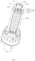
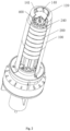
- a heat gun having a flow guiding arrangement comprises: a main body, inside the main body being provided a heating element and a hot air tube 100, the heating element being configured to generate hot air, the hot air generated by the heating element being expelled out through the hot air tube 100.
- the heating element comprises a heating core disposed in the hot air tube 100, the heating core comprising a mounting bracket 200 and a heating filament 300 disposed on the mounting bracket 200, an air inlet 110 and an air outlet 120 being provided at both ends of the hot air tube 100, respectively, wherein the end of the mounting bracket 200 facing the air outlet 120 of the hot air tube 100 is referred to as a front end of the mounting bracket 200, and the opposite end of the mounting bracket 200 is referred to as a rear end of the mounting bracket 200, a flow guiding arrangement 400 inside the hot air tube 100 being disposed at the front end of the mounting bracket 200, a plurality of air guiding passages 440 being obliquely disposed on the flow guiding arrangement 400, the plurality of air guiding passages 440 being arranged about the center of the flow guiding arrangement 400.
- the air entering the hot air tube 100 is heated by the heating core in the hot air tube 100, and the flow guiding arrangement 400 disposed at the end of the mounting bracket 200 of the heating core enables the hot air to form a vortex when passing through the obliquely arranged air guiding passages 440 on the flow guiding arrangement 400, such that the hot air with higher temperature rise and the hot air with lower temperature rise flowing through different positions of the mounting bracket 200 are sufficiently mixed, whereby the hot air expelled out through the air outlet 120 of the hot air tube 100 has a more temperature uniformity, preventing hot air temperature non-uniformity at different positions of the air outlet 120 of the hot air tube 100 from non-uniformly heating a to-be-heated object, which assures heating effect of the heat gun and enhances user experience.
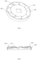
- the flow guiding arrangement 400 comprises a mounting plate 410 mounted on the mounting bracket 200 and a plurality of air bafflers 420 surrounding a peripheral side of the mounting plate 410, the air bafflers 420 being obliquely arranged towards a same direction along the peripheral tangent line of the mounting plate 410 such that the air guiding passages 440 are formed between two neighboring air bafflers 420.
- the length of the air guiding passages 440 on the flow guiding arrangement 400 is extended, such that only with thin mounting plate 410 and air bafflers 420, longer air guiding passages 440 may be achieved, rendering a high spin intensity of the vortex when the hot air flows through the flow guiding arrangement 400, whereby the mixing effect of the hot air with higher temperature rise and the hot air with low higher temperature rise is enhanced, which assures temperature uniformity of the air expelled out of the hot air tube 100.
- the flow guiding arrangement 400 further comprises a mounting ring 430 disposed concentrically with the mounting plate 410, wherein respective inner side of the air bafflers 420 is coupled with the outer peripheral side of the mounting plate 410, and respective outer side of the air bafflers 420 is coupled with the inner wall of the mounting ring 430, such that by securing the inner and outer sides of the air bafflers 420 via the mounting plate 410 and the mounting ring 430, deformations of the air bafflers 420 such as bend may be prevented, which assures shape stability of the air guiding passages 440, whereby a vortex may be continuously formed to mix the hot air with higher temperature rise and the hot air with lower temperature rise when the hot air flows through the flow guiding arrangement 400.
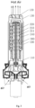
- the mounting bracket 200 comprises a central column 210 and a sleeve 220 sleeved outside the central column 210, wherein the central column 210 is coupled to via a coupler 230 and disposed concentrically with the sleeve 220; on the central column 210 are provided a plurality of venting cavities 211 running through the central column 210, the venting cavities 211 being parallel with the central axis of the central column 210, and the venting cavities 211 being arranged about the central axis of the central column 210.
- the central axis has a tubular shape.
- a heating cavity 240 running through the mounting bracket 200 is formed between the sleeve 220 and the outer sidewall of the central column 210, wherein the heating filament 300 is disposed in the heating cavity 240 and wound around the outer side of the central column 210; the flow guiding arrangement 400 is mounted on the central column 210, the outer diameter of the flow guiding arrangement 400 being identical to that of the central column 210 so as to align the venting cavities 211 with the air guiding passages 440. It is preferable in this embodiment that the plurality of venting cavities 211 are uniformly distributed about the central axis of the central column 210, thereby rendering a more uniform flow rate of the hot air expelled out of the respective air guiding passages 440 disposed surrounding a peripheral side of the flow guiding arrangement 400.
- a mixing cavity 130 is provided in the hot air tube 100, the mixing cavity 130 being disposed between an end of the heating core and the air outlet 120 of the hot air tube 100, whereby the hot air is restricted by the wall of the hot air tube 100 to enhance the effect of mixing the hot air with lower temperature rise and the hot air with higher temperature rise.
- the outer diameter of the flow guiding arrangement 400 may also be identical to that of the sleeve 220 such that the hot air in the venting cavities 211 and the heating cavity 240 may simultaneously flow through the air guiding passages 440 to form a vortex.
- a baffle plate 140 connected inside the hot air tube 100 is further provided in the mixing cavity 130, wherein the baffle plate 140 and the flow guiding arrangement 400 are concentrically arranged; furthermore, an annular air outlet gap 141 is formed between the peripheral side of the baffle plate 140 and the inner wall of the hot air tube 100.
- the baffle plate 140 which directly blocks the hot air with lower temperature rise in the middle of the mixing cavity 130 from being directly expelled out of the air outlet 120, the hot air with lower temperature rise in the middle of the mixing cavity 130, which fails to be mixed with the hot air with higher temperature rise at the peripheral side, is diverted by the baffle plate 140 to flow towards the peripheral side so as to be sufficiently mixed with the hot air with higher temperature rise, and then the mixed hot air is expelled out of the air outlet 120 via the air outlet gap 141, thereby rendering a more uniform, stable outlet air temperature for the heat gun.
- the flow guiding arrangement in this embodiment comprises a mounting plate mounted on the mounting bracket, ventilation holes being obliquely provided in the mounting plate to form air guiding passages.
- the ventilation holes may be provided through top and bottom surfaces of the mounting plate, i.e., an air inlet of the ventilation holes is provided on the bottom surface of the mounting plate, and an air outlet of the ventilation holes is provided on the top surface of the mounting plate; of course, it may be understood that the ventilation holes in this embodiment may also be provided through the bottom surface and side surface of the mounting plate, i.e., the air inlet of the ventilation holes is provided on the bottom surface of the mounting plate, and the air outlet of the ventilation holes is provided on the side surface of the mounting plate.
- At least two superimposed flow guiding arrangements are provided at the end of the mounting bracket.
- the length of air guiding passages increases, which further enhances the spinning intensity of the vortex formed by hot air flowing through the flow guiding arrangements, rendering a better effect of mixing the hot air with higher temperature rise and the hot air with lower temperature rise, further assuring air outlet temperature uniformity of the hot air tube.
Landscapes
- Engineering & Computer Science (AREA)
- Physics & Mathematics (AREA)
- Thermal Sciences (AREA)
- Chemical & Material Sciences (AREA)
- Combustion & Propulsion (AREA)
- Mechanical Engineering (AREA)
- General Engineering & Computer Science (AREA)
- Direct Air Heating By Heater Or Combustion Gas (AREA)
- Nozzles (AREA)
Applications Claiming Priority (2)
| Application Number | Priority Date | Filing Date | Title |
|---|---|---|---|
| CN202110652564.3A CN113566418B (zh) | 2021-06-11 | 2021-06-11 | 一种带有导流件的热风枪 |
| PCT/CN2021/113132 WO2022257270A1 (zh) | 2021-06-11 | 2021-08-17 | 一种带有导流件的热风枪 |
Publications (4)
| Publication Number | Publication Date |
|---|---|
| EP4177535A1 true EP4177535A1 (de) | 2023-05-10 |
| EP4177535A4 EP4177535A4 (de) | 2024-03-06 |
| EP4177535C0 EP4177535C0 (de) | 2025-07-30 |
| EP4177535B1 EP4177535B1 (de) | 2025-07-30 |
Family
ID=78161907
Family Applications (1)
| Application Number | Title | Priority Date | Filing Date |
|---|---|---|---|
| EP21944772.9A Active EP4177535B1 (de) | 2021-06-11 | 2021-08-17 | Heissluftpistole mit strömungsführung |
Country Status (4)
| Country | Link |
|---|---|
| US (1) | US20240035704A1 (de) |
| EP (1) | EP4177535B1 (de) |
| CN (1) | CN113566418B (de) |
| WO (1) | WO2022257270A1 (de) |
Families Citing this family (2)
| Publication number | Priority date | Publication date | Assignee | Title |
|---|---|---|---|---|
| CN116717911B (zh) * | 2023-04-15 | 2025-09-16 | 嘉鹏再升科技(深圳)股份有限公司 | 一种具有冷热风循环调节风门装置的加热炉 |
| CN118881485B (zh) * | 2024-09-29 | 2025-01-21 | 新昌县兴顺机械有限公司 | 一种汽车柴油发动机进气管道总成 |
Family Cites Families (33)
| Publication number | Priority date | Publication date | Assignee | Title |
|---|---|---|---|---|
| US3610881A (en) * | 1968-07-29 | 1971-10-05 | Trigg Stewart | Portable electric air-heating gun and oven |
| SE414666B (sv) * | 1973-08-22 | 1980-08-11 | Fortune William S | Apparat for upphettning av luft. |
| GB8415637D0 (en) * | 1984-06-19 | 1984-07-25 | Black & Decker Inc | Supports for electric heating elements |
| US7860378B2 (en) * | 2005-01-18 | 2010-12-28 | Hakko Corporation | Baffle device, hot air blower for solder treatment, and nozzle for same |
| US20100008655A1 (en) * | 2008-03-07 | 2010-01-14 | Clint Tackitt | Hot air welding gun |
| CN201522108U (zh) * | 2009-09-30 | 2010-07-07 | 黄德超 | 一种热风枪直列式发热芯 |
| JP5773599B2 (ja) * | 2010-09-10 | 2015-09-02 | 株式会社関西電熱 | 熱風発生用ヒータ |
| CN202172499U (zh) * | 2011-05-20 | 2012-03-21 | 黄德超 | 一种热风枪发热芯的陶瓷支架 |
| US20130228232A1 (en) * | 2012-03-02 | 2013-09-05 | Pro-Iroda Industries, Inc. | Hot Air Blower |
| US9182144B2 (en) * | 2012-03-02 | 2015-11-10 | Pro-Iroda Industries, Inc. | Hot air blower |
| CN202933596U (zh) * | 2012-06-02 | 2013-05-15 | 王善玺 | 轴流风机水雾化除尘器 |
| CN203231552U (zh) * | 2013-03-29 | 2013-10-09 | 浙江普莱得电器有限公司 | 热风枪用发热芯组件 |
| CN103453641B (zh) * | 2013-06-03 | 2015-04-29 | 海尔集团公司 | 一种空调送风装置 |
| CN103306865A (zh) * | 2013-06-27 | 2013-09-18 | 成都欣领航科技有限公司 | 一种汽车发动机的改进结构 |
| JP6033261B2 (ja) * | 2013-06-28 | 2016-11-30 | 貞徳舎株式会社 | 熱風生成装置 |
| CN205464710U (zh) * | 2016-04-07 | 2016-08-17 | 克得生 | 新型高效节能快速梅花割嘴 |
| JP6870343B2 (ja) * | 2017-01-24 | 2021-05-12 | 三菱自動車工業株式会社 | 熱風ヒーター |
| CN107101369A (zh) * | 2017-06-15 | 2017-08-29 | 湖北鹤峰金倡工贸有限公司 | 带空气导流罩的电加热装置 |
| CN107655206B (zh) * | 2017-08-21 | 2020-09-15 | 浙江普莱得电器有限公司 | 一种可检测温度的热风枪 |
| CN207180015U (zh) * | 2017-08-21 | 2018-04-03 | 浙江普莱得电器有限公司 | 一种热风枪 |
| CN107941040A (zh) * | 2017-11-16 | 2018-04-20 | 江苏海鸥冷却塔股份有限公司 | 具有三重混流功能的混流装置 |
| CN207859507U (zh) * | 2018-01-18 | 2018-09-14 | 广州市新鼎锋电器设备有限公司 | 一种热风焊枪的热风管结构 |
| CN108826671A (zh) * | 2018-04-09 | 2018-11-16 | 浙江普莱得电器有限公司 | 一种热风枪用发热芯及热风枪 |
| CN108592397B (zh) * | 2018-06-07 | 2023-06-06 | 宜兴市荣泰电器有限公司 | 一种改进的热风枪 |
| CN208765199U (zh) * | 2018-06-29 | 2019-04-19 | 南京美泰环境科技有限公司 | 一种制冷设备冷风和热风排风口装置 |
| CN208735904U (zh) * | 2018-08-08 | 2019-04-12 | 浙江友邦集成吊顶股份有限公司 | 一种集成吊顶用暖风机 |
| CN109323332B (zh) * | 2018-10-24 | 2021-07-23 | 重庆海尔空调器有限公司 | 空调室内机 |
| CN210179895U (zh) * | 2019-04-30 | 2020-03-24 | 惠州市淼鑫健明通讯科技有限公司 | 一种热风枪导风口 |
| CN210035868U (zh) * | 2019-05-09 | 2020-02-07 | 贵州火焰山电器股份有限公司 | 一种暖风机 |
| CN210374061U (zh) * | 2019-05-20 | 2020-04-21 | 石家庄市普兰迪机电设备有限公司 | 一种分体式电加热器 |
| CN212091700U (zh) * | 2020-05-07 | 2020-12-08 | 朱辉 | 一种烟雾净化器 |
| CN112033000A (zh) * | 2020-09-10 | 2020-12-04 | 浪潮商用机器有限公司 | 热风枪热风导流装置及多引脚芯片拆除热风枪 |
| CN112414100A (zh) * | 2020-10-20 | 2021-02-26 | 际华(芜湖)农业科技发展有限责任公司 | 一种谷物烘干机用的热风装置 |
-
2021
- 2021-06-11 CN CN202110652564.3A patent/CN113566418B/zh active Active
- 2021-08-17 EP EP21944772.9A patent/EP4177535B1/de active Active
- 2021-08-17 WO PCT/CN2021/113132 patent/WO2022257270A1/zh not_active Ceased
- 2021-08-17 US US18/021,359 patent/US20240035704A1/en active Pending
Also Published As
| Publication number | Publication date |
|---|---|
| EP4177535A4 (de) | 2024-03-06 |
| WO2022257270A1 (zh) | 2022-12-15 |
| EP4177535C0 (de) | 2025-07-30 |
| CN113566418A (zh) | 2021-10-29 |
| US20240035704A1 (en) | 2024-02-01 |
| CN113566418B (zh) | 2023-04-07 |
| EP4177535B1 (de) | 2025-07-30 |
Similar Documents
| Publication | Publication Date | Title |
|---|---|---|
| EP4177535A1 (de) | Heissluftpistole mit strömungsführung | |
| US20230327228A1 (en) | Battery system having heat-dissipation circulation structure | |
| CN220172968U (zh) | 机壳、动力装置和车辆 | |
| KR102833315B1 (ko) | 배터리 팩 | |
| WO2011099609A1 (ja) | 熱交換器および熱交換器一体型人工肺 | |
| WO2018166064A1 (zh) | 分气结构和燃烧器 | |
| EP4721595A1 (de) | Aerosolerzeugungsvorrichtung | |
| CN109767962B (zh) | 一种一体化冷却的速调管高频结构 | |
| CN210715313U (zh) | 一种带加热功能的无叶风扇 | |
| CN219550867U (zh) | 能够防止干烧的加热体结构及热水器 | |
| CN218958643U (zh) | 交错供油的定子铁芯及油冷电机 | |
| CN215864052U (zh) | 一种出风温度均匀的热风枪 | |
| US20250318018A1 (en) | Aerosol generation device and air heater thereof | |
| CN211668032U (zh) | 一种换热器及冷凝锅炉 | |
| CN216244876U (zh) | 足浴器及用于足浴器的加热装置 | |
| CN224003915U (zh) | 一种加热器 | |
| CN223428781U (zh) | 一种一体式水冷散热板 | |
| CN110594204A (zh) | 具有加热功能的无叶风扇 | |
| CN217381023U (zh) | 鼓风机水冷系统 | |
| CN221636755U (zh) | 一种防涉水的内循环风道设计消毒柜 | |
| CN219379321U (zh) | 一种新型电极杆 | |
| CN114087662B (zh) | 新风装置及空调器 | |
| CN222787223U (zh) | 吹风机 | |
| CN215214120U (zh) | 一种散热结构和应用有该散热结构的风机系统 | |
| CN219018597U (zh) | 电机冷却结构及电机 |
Legal Events
| Date | Code | Title | Description |
|---|---|---|---|
| STAA | Information on the status of an ep patent application or granted ep patent |
Free format text: STATUS: THE INTERNATIONAL PUBLICATION HAS BEEN MADE |
|
| PUAI | Public reference made under article 153(3) epc to a published international application that has entered the european phase |
Free format text: ORIGINAL CODE: 0009012 |
|
| STAA | Information on the status of an ep patent application or granted ep patent |
Free format text: STATUS: REQUEST FOR EXAMINATION WAS MADE |
|
| 17P | Request for examination filed |
Effective date: 20230201 |
|
| AK | Designated contracting states |
Kind code of ref document: A1 Designated state(s): AL AT BE BG CH CY CZ DE DK EE ES FI FR GB GR HR HU IE IS IT LI LT LU LV MC MK MT NL NO PL PT RO RS SE SI SK SM TR |
|
| A4 | Supplementary search report drawn up and despatched |
Effective date: 20240206 |
|
| RIC1 | Information provided on ipc code assigned before grant |
Ipc: F24H 9/1863 20220101ALI20240131BHEP Ipc: F24H 9/18 20220101ALI20240131BHEP Ipc: F24H 9/00 20220101ALI20240131BHEP Ipc: F24H 3/04 20220101AFI20240131BHEP |
|
| DAV | Request for validation of the european patent (deleted) | ||
| DAX | Request for extension of the european patent (deleted) | ||
| GRAP | Despatch of communication of intention to grant a patent |
Free format text: ORIGINAL CODE: EPIDOSNIGR1 |
|
| STAA | Information on the status of an ep patent application or granted ep patent |
Free format text: STATUS: GRANT OF PATENT IS INTENDED |
|
| INTG | Intention to grant announced |
Effective date: 20250408 |
|
| GRAS | Grant fee paid |
Free format text: ORIGINAL CODE: EPIDOSNIGR3 |
|
| GRAA | (expected) grant |
Free format text: ORIGINAL CODE: 0009210 |
|
| STAA | Information on the status of an ep patent application or granted ep patent |
Free format text: STATUS: THE PATENT HAS BEEN GRANTED |
|
| AK | Designated contracting states |
Kind code of ref document: B1 Designated state(s): AL AT BE BG CH CY CZ DE DK EE ES FI FR GB GR HR HU IE IS IT LI LT LU LV MC MK MT NL NO PL PT RO RS SE SI SK SM TR |
|
| REG | Reference to a national code |
Ref country code: GB Ref legal event code: FG4D |
|
| REG | Reference to a national code |
Ref country code: CH Ref legal event code: EP |
|
| REG | Reference to a national code |
Ref country code: DE Ref legal event code: R096 Ref document number: 602021035387 Country of ref document: DE |
|
| REG | Reference to a national code |
Ref country code: IE Ref legal event code: FG4D |
|
| U01 | Request for unitary effect filed |
Effective date: 20250812 |
|
| U07 | Unitary effect registered |
Designated state(s): AT BE BG DE DK EE FI FR IT LT LU LV MT NL PT RO SE SI Effective date: 20250821 |
|
| PGFP | Annual fee paid to national office [announced via postgrant information from national office to epo] |
Ref country code: GB Payment date: 20250820 Year of fee payment: 5 |
|
| U20 | Renewal fee for the european patent with unitary effect paid |
Year of fee payment: 5 Effective date: 20250924 |
|
| PG25 | Lapsed in a contracting state [announced via postgrant information from national office to epo] |
Ref country code: IS Free format text: LAPSE BECAUSE OF FAILURE TO SUBMIT A TRANSLATION OF THE DESCRIPTION OR TO PAY THE FEE WITHIN THE PRESCRIBED TIME-LIMIT Effective date: 20251130 |
|
| PG25 | Lapsed in a contracting state [announced via postgrant information from national office to epo] |
Ref country code: NO Free format text: LAPSE BECAUSE OF FAILURE TO SUBMIT A TRANSLATION OF THE DESCRIPTION OR TO PAY THE FEE WITHIN THE PRESCRIBED TIME-LIMIT Effective date: 20251030 |
|
| PG25 | Lapsed in a contracting state [announced via postgrant information from national office to epo] |
Ref country code: HR Free format text: LAPSE BECAUSE OF FAILURE TO SUBMIT A TRANSLATION OF THE DESCRIPTION OR TO PAY THE FEE WITHIN THE PRESCRIBED TIME-LIMIT Effective date: 20250730 |
|
| PG25 | Lapsed in a contracting state [announced via postgrant information from national office to epo] |
Ref country code: GR Free format text: LAPSE BECAUSE OF FAILURE TO SUBMIT A TRANSLATION OF THE DESCRIPTION OR TO PAY THE FEE WITHIN THE PRESCRIBED TIME-LIMIT Effective date: 20251031 |
|
| PG25 | Lapsed in a contracting state [announced via postgrant information from national office to epo] |
Ref country code: PL Free format text: LAPSE BECAUSE OF FAILURE TO SUBMIT A TRANSLATION OF THE DESCRIPTION OR TO PAY THE FEE WITHIN THE PRESCRIBED TIME-LIMIT Effective date: 20250730 |
|
| PG25 | Lapsed in a contracting state [announced via postgrant information from national office to epo] |
Ref country code: RS Free format text: LAPSE BECAUSE OF FAILURE TO SUBMIT A TRANSLATION OF THE DESCRIPTION OR TO PAY THE FEE WITHIN THE PRESCRIBED TIME-LIMIT Effective date: 20251030 |
|
| PG25 | Lapsed in a contracting state [announced via postgrant information from national office to epo] |
Ref country code: ES Free format text: LAPSE BECAUSE OF FAILURE TO SUBMIT A TRANSLATION OF THE DESCRIPTION OR TO PAY THE FEE WITHIN THE PRESCRIBED TIME-LIMIT Effective date: 20250730 |
|
| REG | Reference to a national code |
Ref country code: CH Ref legal event code: H13 Free format text: ST27 STATUS EVENT CODE: U-0-0-H10-H13 (AS PROVIDED BY THE NATIONAL OFFICE) Effective date: 20260324 |
|
| PG25 | Lapsed in a contracting state [announced via postgrant information from national office to epo] |
Ref country code: SM Free format text: LAPSE BECAUSE OF FAILURE TO SUBMIT A TRANSLATION OF THE DESCRIPTION OR TO PAY THE FEE WITHIN THE PRESCRIBED TIME-LIMIT Effective date: 20250730 |