EP4177427A1 - Antriebsaggregat für eine schliesseinrichtung - Google Patents
Antriebsaggregat für eine schliesseinrichtung Download PDFInfo
- Publication number
- EP4177427A1 EP4177427A1 EP22204432.3A EP22204432A EP4177427A1 EP 4177427 A1 EP4177427 A1 EP 4177427A1 EP 22204432 A EP22204432 A EP 22204432A EP 4177427 A1 EP4177427 A1 EP 4177427A1
- Authority
- EP
- European Patent Office
- Prior art keywords
- operating element
- drive unit
- control device
- housing
- unit according
- Prior art date
- Legal status (The legal status is an assumption and is not a legal conclusion. Google has not performed a legal analysis and makes no representation as to the accuracy of the status listed.)
- Granted
Links
Images


Classifications
-
- E—FIXED CONSTRUCTIONS
- E05—LOCKS; KEYS; WINDOW OR DOOR FITTINGS; SAFES
- E05B—LOCKS; ACCESSORIES THEREFOR; HANDCUFFS
- E05B47/00—Operating or controlling locks or other fastening devices by electric or magnetic means
- E05B47/02—Movement of the bolt by electromagnetic means; Adaptation of locks, latches, or parts thereof, for movement of the bolt by electromagnetic means
-
- E—FIXED CONSTRUCTIONS
- E05—LOCKS; KEYS; WINDOW OR DOOR FITTINGS; SAFES
- E05B—LOCKS; ACCESSORIES THEREFOR; HANDCUFFS
- E05B47/00—Operating or controlling locks or other fastening devices by electric or magnetic means
- E05B47/0001—Operating or controlling locks or other fastening devices by electric or magnetic means with electric actuators; Constructional features thereof
- E05B47/0012—Operating or controlling locks or other fastening devices by electric or magnetic means with electric actuators; Constructional features thereof with rotary electromotors
Definitions
- Closing devices for doors and window doors of buildings have main or secondary locks with sliding or pivoting bolts as closing elements and are well known.
- the electrical actuating device can actively move the closing element or block or release a manual movement.
- Operating elements are mostly used, for example, to reset the electronic control device or to activate certain functions.
- a arranged in a castle drive unit of the type mentioned is for example from WO 2015/189391 A2 known.
- an end plate has a hole behind which the operating element is arranged.
- the operating element is designed as a button and can be operated by the user with the aid of an operating tool.
- the button can be assigned several functions, which are differentiated from one another, for example, based on the duration of operation. Due to the accessibility of the button, however, the electronic control device is exposed to the risk of contamination. In addition, as a result, the electronic control device can easily be manipulated by unauthorized persons.
- buttons detect whether a lock housing is within a corresponding section within a door and whether a screw holds a profile cylinder in the lock.
- the buttons prevent possible manipulation, but the electronic control device cannot be operated via the buttons.
- the invention is based on the problem of developing a drive unit of the type mentioned at the outset in such a way that it can be operated easily, but unauthorized manipulation is made more difficult.
- control element is covered by a detachable cover.
- the control element is not directly visible. This makes unauthorized manipulation more difficult because the existence of this control element is not known to unauthorized persons.
- the cover protects the operating element and thus adjacent components of the electronic control device from contamination. After the cover has been removed, the operating element can be actuated and the control device can thus be operated.
- the operating element can be a button or a rotary control, for example.
- the cover could have a slide or a flap, for example.
- sliders or flaps require a complex guide.
- the cover has a particularly simple construction if the cover has a screw. To operate the control element, the screw can be easily removed and the cover released.
- the drive unit is particularly compact if the operating element is arranged in the housing and if the opening in the housing arranged in front of the operating element has an internal thread for the screw.
- the screw itself is designed as a cover.
- control element is thus protected in a particularly reliable manner.
- existence of the control element cannot be seen from the outside, so that unauthorized attempts at manipulation are largely avoided.
- Such drive units are often arranged in espagnolette locks, in which an espagnolette connects the electrical actuating device to the closing element.
- the closing element can be arranged at a location remote from the electric actuating device and can comprise a lock case, for example.
- the operating element is accessible in every position of the drive unit when the electrical actuating device is connected to a connecting rod and when the connecting rod has a slot in front of the operating element.
- the drive assembly is particularly compact if the electric actuating device has an electric motor drive with a gear.
- the drive unit is particularly compact if the operating element is arranged on a circuit board of the control device.
- an actuating tool has an adjusting pin for actuating the operating element and a stop for support next to the opening.
- This design prevents the stop that the adjusting pin too far or not inserted far enough through the opening.
- the setting pin can be constructed in almost any way and can have, for example, a blunt end for actuating a button, a bar for actuating a turntable or a magnet for actuating a Hall element.
- figure 1 shows a door with a leaf 2 that can be pivoted against a frame 1 and with a locking device 3 designed as an espagnolette lock.
- the locking device 3 has a main lock 4 and two secondary locks 5, 6 connected to the main lock 4.
- the locking device 3 also has a drive unit 7.
- FIG 2 shows the components of the locking device 3 on an enlarged scale.
- the drive rod 8 can be driven via the drive unit 7 and the closing elements 9 - 11 can be extended or retracted from the main lock 4 and the secondary locks 5 , 6 .
- figure 3 shows the drive unit 7 from figure 2 with an engine box 12 in an opened state.
- the drive unit 7 has a connecting rod connecting slide 13 for positive connection with the connecting rod 8 and an electric actuating device 14 for driving the connecting rod connecting slide 13.
- the electric actuating device 14 has an electric motor 15 with a gear 16 for driving the connecting rod connecting slide 13 and thus for indirectly driving the in figure 2 Closing elements 9 - 11 shown.
- the electric motor 15 is controlled by an electronic control device 17 and supplied with electricity from a power source 18 .
- Power source 18 preferably includes multiple electrical cells. Partition walls 19, 20 separate the electrical actuating device 14 from the electronic control device 17 and from the power source 18.
- the electronic control device 16 has a control element 22 arranged on a circuit board 21.
- the control element 22 can be, for example, a function button, a turntable or the like.
- the electronic control device 16 is arranged in a housing 23 .
- the housing 23 is part of the partition walls 19, 20 subdivided engine box 12.
- the housing 23 and adjacent areas of a faceplate 24 and the connecting rod 8 in front of the control element are shown in partial section.
- the housing 23 has an opening 25 with an internal thread 26 for a screw 28 designed as a cover 27 for the operating element 22.
- the screw 28 is also a fastening screw for connecting the housing 23 to the faceplate 24.
- the drive rod 8 has a front of the operating element 22 Slot 29 so that the operating element 22 is accessible in every position of the connecting rod 8.
- the screw 28 is shown here in a position remote from the faceplate 24 . In this position, the operating element 22 can be accessed by an operating tool 30 .
- the actuating tool 30 has an adjusting pin 31 for actuating the operating element 22 and a stop 32 for support on the faceplate 24 next to the opening 25.
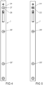
- figure 4 shows in a side view that the in figure 3 illustrated drive unit 7 several screws 28, 28 ', 28 "for screwing with the faceplate has 24. However, only one of the screws 28 is used as a cover 27 for the in figure 3 illustrated operating element 22 is formed.
- figure 5 shows the side view for clarification figure 4 after removing one of the screws 28 designed as a cover 27. This shows that the operating element 22 for the in figure 3 illustrated actuating tool 30 is accessible.
Landscapes
- Physics & Mathematics (AREA)
- Electromagnetism (AREA)
- Power-Operated Mechanisms For Wings (AREA)
Abstract
Description
- Antriebsaggregat für eine Schließeinrichtung einer Tür, einer Fenstertür oder dergleichen mit einer elektrischen Stelleinrichtung für ein Schließorgan, mit einer elektronischen Steuereinrichtung der elektrischen Stelleinrichtung, mit einer Stromquelle zur Versorgung der elektronischen Steuereinrichtung und der elektrischen Stelleinrichtung mit elektrischem Strom, mit einem Gehäuse zur Aufnahme zumindest der Bauteile der Steuereinrichtung und mit einem hinter einer Öffnung des Gehäuses angeordneten Bedienelement der elektronischen Steuereinrichtung.
- Schließeinrichtungen für Türen und Fenstertüren von Gebäuden weisen Haupt- oder Nebenschlösser mit verschiebbaren oder verschwenkbaren Riegeln als Schließorgane auf und sind allgemein bekannt. Die elektrische Stelleinrichtung kann das Schließorgan aktiv bewegen oder eine manuelle Bewegung blockieren oder freigeben. Bedienelemente werden meist eingesetzt, um beispielsweise die elektronische Steuereinrichtung zurückzusetzen oder bestimmte Funktionen zu aktivieren.
- Ein in einem Schloss angeordnetes Antriebsaggregat der eingangs genannten Art ist beispielsweise aus der
WO 2015/189391 A2 bekannt. Bei diesem Antriebsaggregat hat ein Abschlussblech eine Bohrung, hinter der das Bedienelement angeordnet ist. Das Bedienelement ist als Taster ausgebildet und lässt sich mit Hilfe eines Betätigungswerkzeuges vom Benutzer bedienen. Der Taster kann mit mehreren Funktionen belegt sein, die beispielsweise anhand der Betätigungsdauer voneinander unterschieden werden. Durch die Zugänglichkeit des Tasters ist die elektronische Steuereinrichtung jedoch der Gefahr von Verschmutzungen ausgesetzt. Zudem kann hierdurch die elektronische Steuereinrichtung einfach auch von nichtberechtigten Personen manipuliert werden. - Aus der
EP 2 520 746 A1 ist ein elektrisch betätigbares Schloss bekannt geworden, bei dem zwei Taster erfassen, ob sich ein Schlossgehäuse innerhalb eines entsprechenden Ausschnitts innerhalb einer Tür befindet und ob eine Schraube einen Profilzylinder im Schloss hält. Hierdurch verhindern die Taster eine mögliche Manipulation, jedoch lässt sich die elektronische Steuereinrichtung über die Taster nicht bedienen. - Der Erfindung liegt das Problem zugrunde, ein Antriebsaggregat er eingangs genannten Art so weiterzubilden, dass es einfach bedient werden kann, jedoch eine unberechtigte Manipulation erschwert wird.
- Dieses Problem wird erfindungsgemäß dadurch gelöst, dass das Bedienelement von einer lösbaren Abdeckung verdeckt ist.
- Durch diese Gestaltung ist das Bedienelement nicht unmittelbar sichtbar. Hierdurch wird eine unberechtigte Manipulation erschwert, weil die Existenz dieses Bedienelementes unberechtigten Personen nicht bekannt ist. Weiterhin schützt die Abdeckung das Bedienelement und damit angrenzende Bauteile der elektronischen Steuereinrichtung vor Verschmutzung. Nach einem Entfernen der Abdeckung kann das Bedienelement betätigt werden und damit die Steuereinrichtung bedient werden. Das Bedienelement kann beispielsweise ein Taster oder ein Drehsteller sein.
- Die Abdeckung könnte beispielsweise einen Schieber oder eine Klappe aufweisen. Solche Schieber oder Klappen benötigen jedoch eine aufwändige Führung. Die Abdeckung ist gemäß einer anderen vorteilhaften Weiterbildung der Erfindung konstruktiv besonders einfach aufgebaut, wenn die Abdeckung eine Schraube hat. Zur Betätigung des Bedienelementes lässt sich die Schraube einfach entfernen und damit die Abdeckung lösen.
- Das Antriebsaggregat gestaltet sich gemäß einer anderen vorteilhaften Weiterbildung der Erfindung besonders kompakt, wenn das Bedienelement in dem Gehäuse angeordnet ist und wenn die vor dem Bedienelement angeordnete Öffnung im Gehäuse ein Innengewinde für die Schraube hat. Durch diese Gestaltung ist die Schraube selbst als Abdeckung ausgebildet.
- Damit ist das Bedienelement besonders zuverlässig geschützt. Zudem ist von außen die Existenz des Bedienelements nicht ersichtlich, so dass unberechtigte Manipulationsversuche weitgehend vermieden werden.
- Weitere Bauteile zur Montierung der Abdeckung lassen sich gemäß einer anderen vorteilhaften Weiterbildung der Erfindung einfach vermeiden, wenn das Gehäuse mehrere Schrauben zur Befestigung an einer angrenzenden Stulpschiene hat und wenn das Bedienelement unterhalb einer der Schrauben angeordnet ist. Durch diese Gestaltung ist das Bedienelement hinter einer ohnehin zu montierenden Schraube angeordnet. Die Schraube zur Abdeckung des Bedienelementes kann bei der Montage zudem nicht vergessen werden.
- Häufig werden solche Antriebsaggregate in Treibstangenschlössern angeordnet, bei denen eine Treibstange die elektrische Stelleinrichtung mit dem Schließorgan verbindet. Das Schließorgan kann hierdurch in einer von der elektrischen Stelleinrichtung entfernten Stelle angeordnet sein und beispielsweise einen Schlosskasten umfassen. Das Bedienelement ist gemäß einer anderen vorteilhaften Weiterbildung der Erfindung in jeder Stellung des Antriebsaggregates zugänglich, wenn die elektrische Stelleinrichtung mit einer Treibstange verbunden ist und wenn die Treibstange vor dem Bedienelement ein Langloch aufweist.
- Das Antriebsaggregat gestaltet sich gemäß einer anderen vorteilhaften Weiterbildung der Erfindung besonders kompakt, wenn die elektrische Stelleinrichtung einen elektromotorischen Antrieb mit einem Getriebe aufweist.
- Das Antriebsaggregat gestaltet sich gemäß einer anderen vorteilhaften Weiterbildung der Erfindung besonders kompakt, wenn das Bedienelement auf einer Platine der Steuereinrichtung angeordnet ist.
- Eine Beschädigung der elektronischen Steuereinrichtung lässt sich gemäß einer anderen vorteilhaften Weiterbildung der Erfindung einfach vermeiden, wenn ein Betätigungswerkzeug einen Stellpin zur Ansteuerung des Bedienelementes und einen Anschlag zur Abstützung neben der Öffnung hat. Durch diese Gestaltung verhindert der Anschlag, dass der Stellpin zu weit oder nicht weit genug durch die Öffnung eingeführt wird. Der Stellpin kann entsprechend den Erfordernissen des Bedienelementes nahezu beliebig aufgebaut sein und beispielsweise ein stumpfes Ende zur Ansteuerung eines Tasters, einen Steg zur Betätigung eines Drehstellers oder einen Magneten zur Ansteuerung eines Hallelementes aufweisen.
- Die Erfindung lässt zahlreiche Ausführungsformen zu. Zur weiteren Verdeutlichung ihres Grundprinzips ist eine davon in der Zeichnung dargestellt und wird nachfolgend beschrieben. Diese zeigt in
- Fig.1
- eine Tür mit einem Treibstangenbeschlag und einem Treibstangenschloss,
- Fig.2
- das Treibstangenschloss mit einem Antriebsaggregat aus
Figur 1 , - Fig.3
- vergrößert das Antriebsaggregat aus
Figur 2 im Teilschnitt, - Fig.4
- eine Ansicht auf eine das Antriebsaggregat abdeckende Stulpschiene,
- Fig.5
- die Stulpschiene aus
Figur 4 mit einem Betätigungselement des Antriebsaggregats. -
Figur 1 zeigt eine Tür mit einem gegen einen Rahmen 1 schwenkbaren Flügel 2 und mit einer als Treibstangenschloss ausgebildeten Schließeinrichtung 3. Die Schließeinrichtung 3 hat ein Hauptschloss 4 und zwei mit dem Hauptschloss 4 verbundene Nebenschlösser 5, 6. Weiterhin hat die Schließeinrichtung 3 ein Antriebsaggregat 7. -
Figur 2 zeigt vergrößert die Bauteile der Schließeinrichtung 3. Das Hauptschloss 4, die Nebenschlösser 5, 6 und das Antriebsaggregat 7 sind über eine längsverschiebliche Treibstange 8 miteinander verbunden. Über das Antriebsaggregat 7 lässt sich die Treibstange 8 antreiben und Schließorgane 9 - 11 aus dem Hauptschloss 4 und den Nebenschlössern 5, 6 ausfahren oder zurückziehen. -
Figur 3 zeigt das Antriebsaggregat 7 ausFigur 2 mit einem Motorkasten 12 in einem geöffneten Zustand. Das Antriebsaggregat 7 hat einen Treibstangenanschlussschieber 13 zur formschlüssigen Verbindung mit der Treibstange 8 und eine elektrische Stelleinrichtung 14 zum Antrieb des Treibstangenanschlussschiebers 13. Die elektrische Stelleinrichtung 14 hat einen Elektromotor 15 mit einem Getriebe 16 zum Antrieb des Treibstangenanschlussschiebers 13 und damit zum mittelbaren Antrieb der inFigur 2 dargestellten Schließorgane 9 - 11. Der Elektromotor 15 wird von einer elektronischen Steuereinrichtung 17 angesteuert und von einer Stromquelle 18 mit elektrischem Strom versorgt. Die Stromquelle 18 weist vorzugsweise mehrere elektrische Zellen auf. Trennwände 19, 20 trennen die elektrische Stelleinrichtung 14 von der elektronischen Steuereinrichtung 17 und von der Stromquelle 18 ab. Die elektronische Steuereinrichtung 16 hat ein auf einer Platine 21 angeordnetes Bedienelement 22. Bei dem Bedienelement 22 kann es sich beispielsweise um einen Funktionstaster, einen Drehsteller oder dgl. handeln. - Die elektronische Steuereinrichtung 16 ist in einem Gehäuse 23 angeordnet. In der dargestellten Ausführungsform ist das Gehäuse 23 Teil des von Trennwänden 19, 20 unterteilten Motorkastens 12. Das Gehäuse 23 und angrenzende Bereiche einer Stulpschiene 24 und der Treibstange 8 vor dem Bedienelement sind im Teilschnitt dargestellt. Das Gehäuse 23 hat eine Öffnung 25 mit einem Innengewinde 26 für eine als Abdeckung 27 für das Bedienelement 22 ausgebildete Schraube 28. Die Schraube 28 ist zugleich eine Befestigungsschraube zur Verbindung des Gehäuses 23 mit der Stulpschiene 24. Die Treibstange 8 hat vor dem Bedienelement 22 ein Langloch 29, so dass das Bedienelement 22 in jeder Stellung der Treibstange 8 zugänglich ist. Die Schraube 28 ist hier in einer von der Stulpschiene 24 entfernten Stellung dargestellt. In dieser Stellung ist das Bedienelement 22 von einem Betätigungswerkzeug 30 zugänglich. Das Betätigungswerkzeug 30 hat einen Stellpin 31 zur Ansteuerung des Bedienelementes 22 und einen Anschlag 32 zur Abstützung an der Stulpschiene 24 neben der Öffnung 25.
-
Figur 4 zeigt in einer Seitenansicht, dass das inFigur 3 dargestellte Antriebsaggregat 7 mehrere Schrauben 28, 28', 28" zur Verschraubung mit der Stulpschiene 24 hat. Jedoch ist nur eine der Schrauben 28 als Abdeckung 27 für das inFigur 3 dargestellte Bedienelement 22 ausgebildet. -
Figur 5 zeigt zur Verdeutlichung die Seitenansicht ausFigur 4 nach der Entfernung der einen als Abdeckung 27 ausgebildeten Schraube 28. Hierdurch ist zu erkennen, dass das Bedienelement 22 für das inFigur 3 dargestellte Betätigungswerkzeug 30 zugänglich ist.
Claims (8)
- Antriebsaggregat (7) für eine Schließeinrichtung (3) einer Tür, einer Fenstertür oder dergleichen mit einer elektrischen Stelleinrichtung (14) für ein Schließorgan (9 - 11), mit einer elektronischen Steuereinrichtung (17) der elektrischen Stelleinrichtung (14), mit einer Stromquelle (18) zur Versorgung der elektronischen Steuereinrichtung (17) und der elektrischen Stelleinrichtung (14) mit elektrischem Strom, mit einem Gehäuse (23) zur Aufnahme zumindest der Bauteile der Steuereinrichtung (17) und mit einem hinter einer Öffnung (25) des Gehäuses (23) angeordneten Bedienelement (22) der elektronischen Steuereinrichtung (17), dadurch gekennzeichnet, dass das Bedienelement (22) von einer lösbaren Abdeckung (27) verdeckt ist.
- Antriebsaggregat nach Anspruch 1, dadurch gekennzeichnet, dass die Abdeckung (27) eine Schraube (28) hat.
- Antriebsaggregat nach Anspruch 2, dadurch gekennzeichnet, dass das Bedienelement (22) in dem Gehäuse (23) angeordnet ist und dass die vor dem Bedienelement (22) angeordnete Öffnung (25) im Gehäuse (23) ein Innengewinde (26) für die Schraube (28) hat.
- Antriebsaggregat nach Anspruch 2 oder 3, dadurch gekennzeichnet, dass das Gehäuse (23) mehrere Schrauben (28, 28', 28") zur Befestigung an einer angrenzenden Stulpschiene (24) hat und dass das Bedienelement (22) unterhalb einer der Schrauben (28) angeordnet ist.
- Antriebsaggregat nach zumindest einem der Ansprüche 1 bis 4, dadurch gekennzeichnet, dass die elektrische Stelleinrichtung (14) mit einer Treibstange (8) verbunden ist und dass die Treibstange (8) vor dem Bedienelement (22) ein Langloch (29) aufweist.
- Antriebsaggregat nach zumindest einem der Ansprüche 1 bis 5, dadurch gekennzeichnet, dass die elektrische Stelleinrichtung (14) einen elektromotorischen Antrieb mit einem Getriebe (16) aufweist.
- Antriebsaggregat nach zumindest einem der Ansprüche 1 bis 6, dadurch gekennzeichnet, dass das Bedienelement (22) auf einer Platine (21) der Steuereinrichtung (17) angeordnet ist.
- Antriebsaggregat nach zumindest einem der Ansprüche 1 bis 7, dadurch gekennzeichnet, dass ein Betätigungswerkzeug (30) einen Stellpin (29) zur Ansteuerung des Bedienelementes (22) und einen Anschlag (30) zur Abstützung neben der Öffnung (25) hat.
Applications Claiming Priority (1)
| Application Number | Priority Date | Filing Date | Title |
|---|---|---|---|
| DE102021212430.5A DE102021212430A1 (de) | 2021-11-04 | 2021-11-04 | Antriebsaggregat für eine Schließeinrichtung |
Publications (2)
| Publication Number | Publication Date |
|---|---|
| EP4177427A1 true EP4177427A1 (de) | 2023-05-10 |
| EP4177427B1 EP4177427B1 (de) | 2024-05-29 |
Family
ID=84044295
Family Applications (1)
| Application Number | Title | Priority Date | Filing Date |
|---|---|---|---|
| EP22204432.3A Active EP4177427B1 (de) | 2021-11-04 | 2022-10-28 | Antriebsaggregat für eine schliesseinrichtung |
Country Status (2)
| Country | Link |
|---|---|
| EP (1) | EP4177427B1 (de) |
| DE (1) | DE102021212430A1 (de) |
Citations (3)
| Publication number | Priority date | Publication date | Assignee | Title |
|---|---|---|---|---|
| EP2362040A2 (de) * | 2010-02-22 | 2011-08-31 | Carl Fuhr GmbH & Co. KG | Schließanlage |
| EP2520746A1 (de) | 2011-05-06 | 2012-11-07 | Steinbach & Vollmann GmbH & Co. KG | Elektrisch betätigbares Schloss |
| WO2015189391A2 (de) | 2014-06-12 | 2015-12-17 | Baugruppentechnik Pollmeier Gmbh | Verriegelungssystem |
-
2021
- 2021-11-04 DE DE102021212430.5A patent/DE102021212430A1/de not_active Withdrawn
-
2022
- 2022-10-28 EP EP22204432.3A patent/EP4177427B1/de active Active
Patent Citations (3)
| Publication number | Priority date | Publication date | Assignee | Title |
|---|---|---|---|---|
| EP2362040A2 (de) * | 2010-02-22 | 2011-08-31 | Carl Fuhr GmbH & Co. KG | Schließanlage |
| EP2520746A1 (de) | 2011-05-06 | 2012-11-07 | Steinbach & Vollmann GmbH & Co. KG | Elektrisch betätigbares Schloss |
| WO2015189391A2 (de) | 2014-06-12 | 2015-12-17 | Baugruppentechnik Pollmeier Gmbh | Verriegelungssystem |
Also Published As
| Publication number | Publication date |
|---|---|
| DE102021212430A1 (de) | 2023-05-04 |
| EP4177427B1 (de) | 2024-05-29 |
Similar Documents
| Publication | Publication Date | Title |
|---|---|---|
| DE102007017931B4 (de) | Schwenkgriffverschluß | |
| DE69007620T2 (de) | Elektrisch und mechanisch betätigbarer schlossmechanismus. | |
| DE69710140T2 (de) | Türschloss eines fahrzeuges | |
| DE112007001299T5 (de) | Nockenschloss mit rückziehbarem Dorn | |
| DE102011050492A1 (de) | Elektronische Blockiereinrichtung zum Hinzufügen zu einer manuell betätigbaren Sperrvorrichtung einer Tür, eines Fensters oder Dergleichen und Schließsystem | |
| DE102011050495A1 (de) | Elektronische Einheit für eine Sperrvorrichtung und Schließsystem | |
| DE19604442A1 (de) | Sicherheitsvorrichtung für elektronische Schlösser | |
| DE102016109566A1 (de) | Kraftfahrzeugtürverschluss-System | |
| EP2924201A1 (de) | Schloss für eine Tür oder ein Fenster | |
| EP0878600B1 (de) | Elektromotorisch angetriebene Kippöffnungsvorrichtung für Fenster, Türen oder dergleichen | |
| EP4177427B1 (de) | Antriebsaggregat für eine schliesseinrichtung | |
| EP2089786A1 (de) | Systemeinheit für einen rechner | |
| DE102011005758A1 (de) | Kraftfahrzeugschloss | |
| EP1260657B1 (de) | Schlossanordnung | |
| DE10151022A1 (de) | Kraftfahrzeug-Türschloß mit voneinander getrennter Schließeinheit und Steuereinheit | |
| DE102018108999A1 (de) | Betätigungseinheit zum öffnen einer schlossfalle einer tür und/oder klappe eines kraftfahrzeugs | |
| EP1908899A2 (de) | Schließanlage | |
| DE3409391A1 (de) | Magneto - elektronisches system zum oeffnen und schliessen von schloessern | |
| DE202010007509U1 (de) | Schloss und Tür, Fenster o.dgl. mit einem Schloss | |
| DE102013019061A1 (de) | Vorrichtung zur Verriegelung einer beweglichen elektrischen Baugruppe | |
| WO2020064772A1 (de) | Betätigungshandhabe mit zutrittskontrollsystem | |
| EP3118396B1 (de) | Kantriegel mit elektrischem motor | |
| DE102015117039A1 (de) | Motorbetriebener Schrankverschluss | |
| EP4177426B1 (de) | Antriebsaggregat für eine schliesseinrichtung, insbesondere für ein treibstangenschloss einer tür | |
| WO2016040970A1 (de) | Türschild für einen türbeschlag |
Legal Events
| Date | Code | Title | Description |
|---|---|---|---|
| PUAI | Public reference made under article 153(3) epc to a published international application that has entered the european phase |
Free format text: ORIGINAL CODE: 0009012 |
|
| STAA | Information on the status of an ep patent application or granted ep patent |
Free format text: STATUS: THE APPLICATION HAS BEEN PUBLISHED |
|
| AK | Designated contracting states |
Kind code of ref document: A1 Designated state(s): AL AT BE BG CH CY CZ DE DK EE ES FI FR GB GR HR HU IE IS IT LI LT LU LV MC ME MK MT NL NO PL PT RO RS SE SI SK SM TR |
|
| P01 | Opt-out of the competence of the unified patent court (upc) registered |
Effective date: 20230512 |
|
| STAA | Information on the status of an ep patent application or granted ep patent |
Free format text: STATUS: REQUEST FOR EXAMINATION WAS MADE |
|
| 17P | Request for examination filed |
Effective date: 20231011 |
|
| RBV | Designated contracting states (corrected) |
Designated state(s): AL AT BE BG CH CY CZ DE DK EE ES FI FR GB GR HR HU IE IS IT LI LT LU LV MC ME MK MT NL NO PL PT RO RS SE SI SK SM TR |
|
| RIC1 | Information provided on ipc code assigned before grant |
Ipc: E05B 47/02 20060101ALI20231116BHEP Ipc: E05B 47/00 20060101AFI20231116BHEP |
|
| GRAP | Despatch of communication of intention to grant a patent |
Free format text: ORIGINAL CODE: EPIDOSNIGR1 |
|
| STAA | Information on the status of an ep patent application or granted ep patent |
Free format text: STATUS: GRANT OF PATENT IS INTENDED |
|
| INTG | Intention to grant announced |
Effective date: 20240112 |
|
| GRAS | Grant fee paid |
Free format text: ORIGINAL CODE: EPIDOSNIGR3 |
|
| GRAA | (expected) grant |
Free format text: ORIGINAL CODE: 0009210 |
|
| STAA | Information on the status of an ep patent application or granted ep patent |
Free format text: STATUS: THE PATENT HAS BEEN GRANTED |
|
| AK | Designated contracting states |
Kind code of ref document: B1 Designated state(s): AL AT BE BG CH CY CZ DE DK EE ES FI FR GB GR HR HU IE IS IT LI LT LU LV MC ME MK MT NL NO PL PT RO RS SE SI SK SM TR |
|
| REG | Reference to a national code |
Ref country code: CH Ref legal event code: EP |
|
| REG | Reference to a national code |
Ref country code: IE Ref legal event code: FG4D Free format text: LANGUAGE OF EP DOCUMENT: GERMAN |
|
| REG | Reference to a national code |
Ref country code: DE Ref legal event code: R096 Ref document number: 502022000968 Country of ref document: DE |
|
| REG | Reference to a national code |
Ref country code: LT Ref legal event code: MG9D |
|
| REG | Reference to a national code |
Ref country code: NL Ref legal event code: MP Effective date: 20240529 |
|
| PG25 | Lapsed in a contracting state [announced via postgrant information from national office to epo] |
Ref country code: IS Free format text: LAPSE BECAUSE OF FAILURE TO SUBMIT A TRANSLATION OF THE DESCRIPTION OR TO PAY THE FEE WITHIN THE PRESCRIBED TIME-LIMIT Effective date: 20240929 |
|
| PG25 | Lapsed in a contracting state [announced via postgrant information from national office to epo] |
Ref country code: BG Free format text: LAPSE BECAUSE OF FAILURE TO SUBMIT A TRANSLATION OF THE DESCRIPTION OR TO PAY THE FEE WITHIN THE PRESCRIBED TIME-LIMIT Effective date: 20240529 |
|
| PG25 | Lapsed in a contracting state [announced via postgrant information from national office to epo] |
Ref country code: HR Free format text: LAPSE BECAUSE OF FAILURE TO SUBMIT A TRANSLATION OF THE DESCRIPTION OR TO PAY THE FEE WITHIN THE PRESCRIBED TIME-LIMIT Effective date: 20240529 Ref country code: FI Free format text: LAPSE BECAUSE OF FAILURE TO SUBMIT A TRANSLATION OF THE DESCRIPTION OR TO PAY THE FEE WITHIN THE PRESCRIBED TIME-LIMIT Effective date: 20240529 |
|
| PG25 | Lapsed in a contracting state [announced via postgrant information from national office to epo] |
Ref country code: GR Free format text: LAPSE BECAUSE OF FAILURE TO SUBMIT A TRANSLATION OF THE DESCRIPTION OR TO PAY THE FEE WITHIN THE PRESCRIBED TIME-LIMIT Effective date: 20240830 |
|
| PG25 | Lapsed in a contracting state [announced via postgrant information from national office to epo] |
Ref country code: ES Free format text: LAPSE BECAUSE OF FAILURE TO SUBMIT A TRANSLATION OF THE DESCRIPTION OR TO PAY THE FEE WITHIN THE PRESCRIBED TIME-LIMIT Effective date: 20240529 |
|
| PG25 | Lapsed in a contracting state [announced via postgrant information from national office to epo] |
Ref country code: PL Free format text: LAPSE BECAUSE OF FAILURE TO SUBMIT A TRANSLATION OF THE DESCRIPTION OR TO PAY THE FEE WITHIN THE PRESCRIBED TIME-LIMIT Effective date: 20240529 |
|
| PG25 | Lapsed in a contracting state [announced via postgrant information from national office to epo] |
Ref country code: LV Free format text: LAPSE BECAUSE OF FAILURE TO SUBMIT A TRANSLATION OF THE DESCRIPTION OR TO PAY THE FEE WITHIN THE PRESCRIBED TIME-LIMIT Effective date: 20240529 |
|
| PG25 | Lapsed in a contracting state [announced via postgrant information from national office to epo] |
Ref country code: PL Free format text: LAPSE BECAUSE OF FAILURE TO SUBMIT A TRANSLATION OF THE DESCRIPTION OR TO PAY THE FEE WITHIN THE PRESCRIBED TIME-LIMIT Effective date: 20240529 Ref country code: NO Free format text: LAPSE BECAUSE OF FAILURE TO SUBMIT A TRANSLATION OF THE DESCRIPTION OR TO PAY THE FEE WITHIN THE PRESCRIBED TIME-LIMIT Effective date: 20240829 Ref country code: LV Free format text: LAPSE BECAUSE OF FAILURE TO SUBMIT A TRANSLATION OF THE DESCRIPTION OR TO PAY THE FEE WITHIN THE PRESCRIBED TIME-LIMIT Effective date: 20240529 Ref country code: IS Free format text: LAPSE BECAUSE OF FAILURE TO SUBMIT A TRANSLATION OF THE DESCRIPTION OR TO PAY THE FEE WITHIN THE PRESCRIBED TIME-LIMIT Effective date: 20240929 Ref country code: HR Free format text: LAPSE BECAUSE OF FAILURE TO SUBMIT A TRANSLATION OF THE DESCRIPTION OR TO PAY THE FEE WITHIN THE PRESCRIBED TIME-LIMIT Effective date: 20240529 Ref country code: GR Free format text: LAPSE BECAUSE OF FAILURE TO SUBMIT A TRANSLATION OF THE DESCRIPTION OR TO PAY THE FEE WITHIN THE PRESCRIBED TIME-LIMIT Effective date: 20240830 Ref country code: FI Free format text: LAPSE BECAUSE OF FAILURE TO SUBMIT A TRANSLATION OF THE DESCRIPTION OR TO PAY THE FEE WITHIN THE PRESCRIBED TIME-LIMIT Effective date: 20240529 Ref country code: ES Free format text: LAPSE BECAUSE OF FAILURE TO SUBMIT A TRANSLATION OF THE DESCRIPTION OR TO PAY THE FEE WITHIN THE PRESCRIBED TIME-LIMIT Effective date: 20240529 Ref country code: BG Free format text: LAPSE BECAUSE OF FAILURE TO SUBMIT A TRANSLATION OF THE DESCRIPTION OR TO PAY THE FEE WITHIN THE PRESCRIBED TIME-LIMIT Effective date: 20240529 Ref country code: RS Free format text: LAPSE BECAUSE OF FAILURE TO SUBMIT A TRANSLATION OF THE DESCRIPTION OR TO PAY THE FEE WITHIN THE PRESCRIBED TIME-LIMIT Effective date: 20240829 |
|
| REG | Reference to a national code |
Ref country code: DE Ref legal event code: R081 Ref document number: 502022000968 Country of ref document: DE Owner name: AUG. WINKHAUS SE & CO. KG, DE Free format text: FORMER OWNER: AUG. WINKHAUS GMBH & CO. KG, 48291 TELGTE, DE Ref country code: DE Ref legal event code: R081 Ref document number: 502022000968 Country of ref document: DE Owner name: AUG. WINKHAUS SE, DE Free format text: FORMER OWNER: AUG. WINKHAUS GMBH & CO. KG, 48291 TELGTE, DE |
|
| PG25 | Lapsed in a contracting state [announced via postgrant information from national office to epo] |
Ref country code: NL Free format text: LAPSE BECAUSE OF FAILURE TO SUBMIT A TRANSLATION OF THE DESCRIPTION OR TO PAY THE FEE WITHIN THE PRESCRIBED TIME-LIMIT Effective date: 20240529 |
|
| PG25 | Lapsed in a contracting state [announced via postgrant information from national office to epo] |
Ref country code: NL Free format text: LAPSE BECAUSE OF FAILURE TO SUBMIT A TRANSLATION OF THE DESCRIPTION OR TO PAY THE FEE WITHIN THE PRESCRIBED TIME-LIMIT Effective date: 20240529 |
|
| RAP4 | Party data changed (patent owner data changed or rights of a patent transferred) |
Owner name: AUG. WINKHAUS SE & CO. KG |
|
| PG25 | Lapsed in a contracting state [announced via postgrant information from national office to epo] |
Ref country code: DK Free format text: LAPSE BECAUSE OF FAILURE TO SUBMIT A TRANSLATION OF THE DESCRIPTION OR TO PAY THE FEE WITHIN THE PRESCRIBED TIME-LIMIT Effective date: 20240529 |
|
| PG25 | Lapsed in a contracting state [announced via postgrant information from national office to epo] |
Ref country code: EE Free format text: LAPSE BECAUSE OF FAILURE TO SUBMIT A TRANSLATION OF THE DESCRIPTION OR TO PAY THE FEE WITHIN THE PRESCRIBED TIME-LIMIT Effective date: 20240529 |
|
| PG25 | Lapsed in a contracting state [announced via postgrant information from national office to epo] |
Ref country code: CZ Free format text: LAPSE BECAUSE OF FAILURE TO SUBMIT A TRANSLATION OF THE DESCRIPTION OR TO PAY THE FEE WITHIN THE PRESCRIBED TIME-LIMIT Effective date: 20240529 |
|
| PG25 | Lapsed in a contracting state [announced via postgrant information from national office to epo] |
Ref country code: RO Free format text: LAPSE BECAUSE OF FAILURE TO SUBMIT A TRANSLATION OF THE DESCRIPTION OR TO PAY THE FEE WITHIN THE PRESCRIBED TIME-LIMIT Effective date: 20240529 Ref country code: SK Free format text: LAPSE BECAUSE OF FAILURE TO SUBMIT A TRANSLATION OF THE DESCRIPTION OR TO PAY THE FEE WITHIN THE PRESCRIBED TIME-LIMIT Effective date: 20240529 |
|
| PG25 | Lapsed in a contracting state [announced via postgrant information from national office to epo] |
Ref country code: SM Free format text: LAPSE BECAUSE OF FAILURE TO SUBMIT A TRANSLATION OF THE DESCRIPTION OR TO PAY THE FEE WITHIN THE PRESCRIBED TIME-LIMIT Effective date: 20240529 |
|
| PG25 | Lapsed in a contracting state [announced via postgrant information from national office to epo] |
Ref country code: SM Free format text: LAPSE BECAUSE OF FAILURE TO SUBMIT A TRANSLATION OF THE DESCRIPTION OR TO PAY THE FEE WITHIN THE PRESCRIBED TIME-LIMIT Effective date: 20240529 Ref country code: SK Free format text: LAPSE BECAUSE OF FAILURE TO SUBMIT A TRANSLATION OF THE DESCRIPTION OR TO PAY THE FEE WITHIN THE PRESCRIBED TIME-LIMIT Effective date: 20240529 Ref country code: RO Free format text: LAPSE BECAUSE OF FAILURE TO SUBMIT A TRANSLATION OF THE DESCRIPTION OR TO PAY THE FEE WITHIN THE PRESCRIBED TIME-LIMIT Effective date: 20240529 Ref country code: EE Free format text: LAPSE BECAUSE OF FAILURE TO SUBMIT A TRANSLATION OF THE DESCRIPTION OR TO PAY THE FEE WITHIN THE PRESCRIBED TIME-LIMIT Effective date: 20240529 Ref country code: DK Free format text: LAPSE BECAUSE OF FAILURE TO SUBMIT A TRANSLATION OF THE DESCRIPTION OR TO PAY THE FEE WITHIN THE PRESCRIBED TIME-LIMIT Effective date: 20240529 Ref country code: CZ Free format text: LAPSE BECAUSE OF FAILURE TO SUBMIT A TRANSLATION OF THE DESCRIPTION OR TO PAY THE FEE WITHIN THE PRESCRIBED TIME-LIMIT Effective date: 20240529 |
|
| PG25 | Lapsed in a contracting state [announced via postgrant information from national office to epo] |
Ref country code: IT Free format text: LAPSE BECAUSE OF FAILURE TO SUBMIT A TRANSLATION OF THE DESCRIPTION OR TO PAY THE FEE WITHIN THE PRESCRIBED TIME-LIMIT Effective date: 20240529 |
|
| REG | Reference to a national code |
Ref country code: DE Ref legal event code: R097 Ref document number: 502022000968 Country of ref document: DE |
|
| PLBE | No opposition filed within time limit |
Free format text: ORIGINAL CODE: 0009261 |
|
| STAA | Information on the status of an ep patent application or granted ep patent |
Free format text: STATUS: NO OPPOSITION FILED WITHIN TIME LIMIT |
|
| PG25 | Lapsed in a contracting state [announced via postgrant information from national office to epo] |
Ref country code: SI Free format text: LAPSE BECAUSE OF FAILURE TO SUBMIT A TRANSLATION OF THE DESCRIPTION OR TO PAY THE FEE WITHIN THE PRESCRIBED TIME-LIMIT Effective date: 20240529 |
|
| 26N | No opposition filed |
Effective date: 20250303 |
|
| PG25 | Lapsed in a contracting state [announced via postgrant information from national office to epo] |
Ref country code: MC Free format text: LAPSE BECAUSE OF FAILURE TO SUBMIT A TRANSLATION OF THE DESCRIPTION OR TO PAY THE FEE WITHIN THE PRESCRIBED TIME-LIMIT Effective date: 20240529 |
|
| PG25 | Lapsed in a contracting state [announced via postgrant information from national office to epo] |
Ref country code: LU Free format text: LAPSE BECAUSE OF NON-PAYMENT OF DUE FEES Effective date: 20241028 Ref country code: BE Free format text: LAPSE BECAUSE OF NON-PAYMENT OF DUE FEES Effective date: 20241031 |
|
| REG | Reference to a national code |
Ref country code: BE Ref legal event code: MM Effective date: 20241031 |
|
| REG | Reference to a national code |
Ref country code: DE Ref legal event code: R081 Ref document number: 502022000968 Country of ref document: DE Owner name: AUG. WINKHAUS SE, DE Free format text: FORMER OWNER: AUG. WINKHAUS SE & CO. KG, 48291 TELGTE, DE |
|
| PG25 | Lapsed in a contracting state [announced via postgrant information from national office to epo] |
Ref country code: SE Free format text: LAPSE BECAUSE OF FAILURE TO SUBMIT A TRANSLATION OF THE DESCRIPTION OR TO PAY THE FEE WITHIN THE PRESCRIBED TIME-LIMIT Effective date: 20240529 |
|
| PG25 | Lapsed in a contracting state [announced via postgrant information from national office to epo] |
Ref country code: IE Free format text: LAPSE BECAUSE OF NON-PAYMENT OF DUE FEES Effective date: 20241028 |
|
| PGFP | Annual fee paid to national office [announced via postgrant information from national office to epo] |
Ref country code: DE Payment date: 20251020 Year of fee payment: 4 |
|
| PGFP | Annual fee paid to national office [announced via postgrant information from national office to epo] |
Ref country code: AT Payment date: 20260113 Year of fee payment: 4 |
|
| PGFP | Annual fee paid to national office [announced via postgrant information from national office to epo] |
Ref country code: FR Payment date: 20251027 Year of fee payment: 4 |
|
| PG25 | Lapsed in a contracting state [announced via postgrant information from national office to epo] |
Ref country code: HU Free format text: LAPSE BECAUSE OF FAILURE TO SUBMIT A TRANSLATION OF THE DESCRIPTION OR TO PAY THE FEE WITHIN THE PRESCRIBED TIME-LIMIT; INVALID AB INITIO Effective date: 20221028 |
|
| PG25 | Lapsed in a contracting state [announced via postgrant information from national office to epo] |
Ref country code: CY Free format text: LAPSE BECAUSE OF FAILURE TO SUBMIT A TRANSLATION OF THE DESCRIPTION OR TO PAY THE FEE WITHIN THE PRESCRIBED TIME-LIMIT; INVALID AB INITIO Effective date: 20221028 |