-
Die vorliegende Erfindung betrifft ein System und Verfahren zum Herstellen von Betonprodukten, insbesondere rohrförmigen Betonprodukten bzw. Betonrohren, im Gießverfahren mittels eine Außenform aufweisenden Gießformen oder mittels Außen- und Innenformen aufweisenden Gießformen.
Hintergrund der Erfindung
-
Im Stand der Technik sind teilautomatisierte Anlagen und Systeme zum Herstellen von Betonprodukten, insbesondere Betonrohren, bekannt. Hierbei erfolgt die teilautomatisierte Herstellung von beispielsweise rohrförmigen Betonprodukten üblicherweise im Rüttelpressverfahren mittels Vibrationsverdichtungseinrichtungen oder im Rotationspressverfahren, bei dem die Verdichtung und innere Formgebung der rohrförmigen Betonprodukte mittels eines Rollenkopfes erfolgt.
-
Jedoch sind Herstellungssysteme zum Herstellen von rohrförmigen Betonprodukten im Rüttelpressverfahren bzw. im Rotationspressverfahren kostenaufwendig und benötigen eine große Aufstellfläche, da aufwendige und platzraubende Vibrationsverdichtungseinrichtungen bzw. Rotationspresseinrichtungen bereitgestellt werden müssen und zudem ein großes Produktlager sowie ein hoher Platzbedarf für zusätzlich erforderliche Muffen- und Formenlager benötigt wird. Zusätzlich sind aufwendige Umrüstvorgänge erforderlich, wenn Produkte anderer Größendimensionen hergestellt werden sollen.
-
Des Weiteren ist es bekannt, einzelne rohrförmige Betonprodukte in hoher Qualität im Gießverfahren in einer ortsgebundenen stehenden Schalung herzustellen. Jedoch ist es aufgrund der längeren benötigten Aushärtezeiten des Betons signifikant erschwert, ein automatisiertes Herstellungssystem bereitzustellen, bei dem rohrförmige Betonprodukte im kostengünstigen und qualitativ hochwertigen Gießverfahren automatisiert gefertigt werden können.
-
In diesem Zusammenhang wurden im Stand der Technik automatisierte Systeme zum Herstellen von rohrförmigen Betonprodukten, insbesondere Betonrohren, vorgeschlagen, bei denen Betonprodukte in einem automatisierten Herstellungszyklus programmgesteuert und getaktet in einem Umlaufsystem zwischen einzelnen vollautomatisierten Fertigungsstationen eines Fertigungsbereichs mittels einer Formfördereinrichtung befördert werden und im Gießverfahren hergestellt werden.
-
Ein derartiges System ist z.B. in der
DE 10 2012 217 324 A1 beschrieben. Das System der
DE 10 2012 217 324 A1 umfasst einen Fertigungsbereich mit einer Mehrzahl vollautomatisierter Fertigungsstationen und eine Formfördereinrichtung zum Befördern der Gießformen bzw. der Außenform und des Formkerns (Innenform) von Gießformen zwischen den Fertigungsstationen. Der Fertigungsbereich weist eine Entschalungsstation zum Entfernen einer Außenform von einer an der Entschalungsstation positionierten Gießform und zum Entfernen eines ausgehärteten rohrförmigen Betonprodukts von einem an der Entschalungsstation positionierten Formkern auf.
-
Weiterhin weist der Fertigungsbereich eine Reinigungsstation zum Reinigen eines an der Reinigungsstation positionierten Formkerns und zum Reinigen einer an der zumindest einen Reinigungsstation positionierten Außenform, eine Formrüststation zum Zusammensetzen einer Gießform aus einer Außenform und einem Formkern und eine Füllstation zum Befüllen einer zusammengesetzten Gießform mit Beton auf.
-
Ausgehend von dem vorstehend beschriebenen System der
DE 10 2012 217 324 A1 ist es eine Aufgabe der vorliegenden Erfindung, ein System und ein Verfahren bereitzustellen bzw. das Verfahren und System der
DE 10 2012 217 324 A1 weiterzuentwickeln, und die Variabilität der Einsetzbarkeit des Herstellungssystems zu erweitern und gleichzeitig die Einsetzbarkeit, Zuverlässigkeit und Effizienz des automatisierten Umlaufzyklus bzw. des Gesamtsystems zu verbessern.
Zusammenfassung der Erfindung
-
Im Hinblick auf die vorstehend genannte Aufgabe der vorliegenden Erfindung werden gemäß der vorliegenden Erfindung ein System zum Herstellen von Betonprodukten, insbesondere rohrförmigen Betonprodukten bzw. Betonrohren, im Gießverfahren mittels bevorzugt stehenden Gießformen gemäß Anspruch 1 und ein Verfahren zum Herstellen von Betonprodukten, insbesondere rohrförmigen Betonprodukten bzw. Betonrohren, im Gießverfahren gemäß Anspruch 26 vorgeschlagen. Abhängige Ansprüche betreffen bevorzugte Ausführungsbeispiele der vorliegenden Erfindung.
-
Gemäß eines Aspekts der vorliegenden Erfindung wird ein System zum Herstellen von Betonprodukten im Gießverfahren mittels aus entsprechenden Außen- und Innenformen zusammengesetzten Gießformen, mit einem programmgesteuerten, automatisierten Umlaufsystem vorgeschlagen.
-
Das Umlaufsystem umfasst bevorzugt: einen Aushärtebereich zum Lagern von in einer jeweiligen Gießform aushärtenden Betonprodukten; einen automatisierten Fertigungsbereich mit einer Mehrzahl von automatisierten Fertigungseinrichtungen; und/oder eine Fördereinrichtung mit automatisierten Umlaufförderabschnitten zum Befördern der Gießformen bzw. der Außen- und Innenformen der Gießformen von dem Aushärtebereich in den automatisierten Fertigungsbereich, zwischen den jeweiligen Fertigungseinrichtungen des automatisierten Fertigungsbereichs und aus dem automatisierten Fertigungsbereich in den Aushärtebereich.
-
Der automatisierte Fertigungsbereich des Umlaufsystems weist bevorzugt auf: eine automatisierte Entschalungseinrichtung zum Entschalen einer aus dem Aushärtebereich kommenden Gießform und zum Entnehmen eines ausgehärteten Betonprodukts, eine automatisierte Reinigungseinrichtung zum Reinigen der Außen- und Innenformen einer an der Entschalungseinrichtung entschalten Gießform, eine automatisierte Formrüsteinrichtung zum Zusammensetzen einer Gießform aus entsprechenden an der Reinigungseinrichtung gereinigten Außen- und Innenformen, und/oder eine automatisierte Fülleinrichtung zum Befüllen einer oder mehrerer zusammengesetzter Gießformen mit Beton.
-
Bevorzugt umfasst das System weiterhin eine manuell bedienbare Formrüsteinrichtung mit zumindest einer Formrüststation zum manuell unterstützten Zusammensetzen einer Gießform aus entsprechenden Außen- und Innenformen.
-
Bevorzugt umfasst die Fördereinrichtung einen automatisierten Zuführungsförderabschnitt, der dazu eingerichtet ist, eine an der manuell bedienbaren Formrüsteinrichtung zusammengesetzte Gießform (z.B. vor der Fülleinrichtung des Fertigungsbereichs des Umlaufsystems und insbesondere bevorzugt programmgesteuert) dem automatisiertem Umlaufsystem zuzuführen.
-
Bevorzugt ist der Zuführungsförderabschnitt dazu eingerichtet, eine an der manuell bedienbaren Formrüsteinrichtung zusammengesetzte Gießform dem automatisiertem Umlaufsystem vor der Fülleinrichtung des Fertigungsbereichs des Umlaufsystems zuzuführen. Alternative kann der Zuführungsförderabschnitt dazu eingerichtet sein, eine an der manuell bedienbaren Formrüsteinrichtung zusammengesetzte Gießform einer weiteren Fülleinrichtung zuzuführen und/oder von der weiteren Fülleinrichtung dem Aushärtebereich des automatisierten Umlaufsystems zuzuführen.
-
Bevorzugt ist ein weiterer Förderabschnitt dazu eingerichtet, eine Gießform aus dem Aushärtebereich des automatisierten Umlaufsystems dem manuellen Rüstbereich zuzuführen.
-
Bevorzugt umfasst das System eine automatisierte Übergabeeinrichtung, die dazu eingerichtet ist, sowohl mittels des Zuführungsförderabschnitts von der manuell bedienbaren Formrüsteinrichtung zugeführte Gießformen als auch mittels eines Umlaufförderabschnitts von der automatisierten Formrüsteinrichtung zugeführte Gießformen an eine oder mehrere Füllstationen der automatisierten Fülleinrichtung zu übergeben.
-
Bevorzugt weist die Übergabeeinrichtung ein programmgesteuertes Weichenstellsystem zur weichenstellbaren Zusammenführung des von der manuell bedienbaren Formrüsteinrichtung kommenden Zuführungsförderabschnitts und des von der automatisierten Formrüsteinrichtung kommenden Umlaufförderabschnitts vor der automatisierten Fülleinrichtung auf.
-
Bevorzugt weist die Übergabeeinrichtung einen programmgesteuerten Roboterkran auf, der dazu eingerichtet ist, eine zugeführte Gießform von dem von der manuell bedienbaren Formrüsteinrichtung kommenden Zuführungsförderabschnitt aufzunehmen als auch eine zugeführte Gießform von dem von der automatisierten Formrüsteinrichtung kommenden Umlaufförderabschnitt aufzunehmen, und/oder eine aufgenommene Gießform der automatisierten Fülleinrichtung oder einem oder mehreren der automatisierten Fülleinrichtung zuführenden Umlaufförderabschnitten zu übergeben.
-
Bevorzugt weist die Übergabeeinrichtung einen programmgesteuerten, verfahrbaren Verschiebetisch auf, der dazu eingerichtet ist, eine zugeführte Gießform von dem von der manuell bedienbaren Formrüsteinrichtung kommenden Zuführungsförderabschnitt aufzunehmen als auch eine zugeführte Gießform von dem von der automatisierten Formrüsteinrichtung kommenden Umlaufförderabschnitt aufzunehmen, und/oder eine aufgenommene Gießform der automatisierten Fülleinrichtung oder einem oder mehreren der automatisierten Fülleinrichtung zuführenden Umlaufförderabschnitten zu übergeben.
-
Vorzugsweise ist die Übergabeeinrichtung weiterhin dazu eingerichtet ist, eine in der automatisierten Fülleinrichtung befüllte Gießform zu entnehmen und vorzugsweise einer Ausgabeeinrichtung zum Ausgeben der befüllten Gießform in den Aushärtebereich zuzuführen.
-
Bevorzugt weist die Ausgabeeinrichtung einen Zwischenlagerbereich zum Zwischenlagern befüllter Gießformen vor der Ausgabe in den Aushärtebereich auf.
-
Bevorzugt weist die Ausgabeeinrichtung einen programmgesteuerten Manipulator auf, der dazu eingerichtet ist, eine Gießform und/oder eine Gruppe mehrerer Gießformen in den Aushärtebereich und/oder an ein zum Aushärtebereich führenden Förderabschnitt der Fördereinrichtung zu übergeben.
-
Bevorzugt weist die Ausgabeeinrichtung eine programmgesteuerte, automatisierte Einsetzvorrichtung zum Einsetzen einer Muffe an einer befüllten Gießform auf.
-
Bevorzugt weist die Fülleinrichtung eine Mehrzahl von automatisierten Füllstationen zum parallelen Befüllen mehrerer Gießformen mit Beton an der Fülleinrichtung auf.
-
Bevorzugt weist das System eine Steuereinrichtung zur programmgesteuerten Steuerung der Fertigungseinrichtungen des automatisierten Fertigungsbereichs des Umlaufsystems und der Fördereinrichtung auf.
-
Bevorzugt ist die Steuerungseinrichtung dazu eingerichtet, zu jedem Betonprodukt bzw. zu jeder zusammengesetzten Gießform eine entsprechende Füllzeit zu speichern, und das Zuführen von Gießformen an die Mehrzahl von automatisierten Füllstationen zum parallelen Befüllen mehrerer Gießformen mit Beton an der Fülleinrichtung in Abhängigkeit von den gespeicherten entsprechenden Füllzeiten der Gießformen zu steuern.
-
Bevorzugt ist die Steuerungseinrichtung dazu eingerichtet, zu jedem Betonprodukt bzw. zu jeder zusammengesetzten Gießform eine entsprechende Betonrezeptur zu speichern, und für das Befüllen einer Gießform an einer automatisierten Füllstation in Abhängigkeit einer gespeicherten entsprechenden Betonrezeptur zu steuern.
-
Bevorzugt ist ein von der automatisierten Formrüsteinrichtung zuführender Umlaufförderabschnitt dazu eingerichtet, mehrere von der automatisierten Formrüsteinrichtung kommende Gießformen aufzunehmen, vorzugsweise um aufgenommene Gießformen vor dem Zuführen zu der automatisierten Fülleinrichtung zwischenzulagern, vorzugsweise derart, dass der von der automatisierten Formrüsteinrichtung zuführende Umlaufförderabschnitt einen ersten Pufferbereich aufweist.
-
Bevorzugt ist der von der manuell bedienbaren Formrüsteinrichtung zuführende Zuführungsförderabschnitt dazu eingerichtet, mehrere von der manuell bedienbaren Formrüsteinrichtung kommende Gießformen aufzunehmen, vorzugsweise um aufgenommene Gießformen vor dem Einbringen in das Umlaufsystem bzw. vor dem Zuführen zu der automatisierten Fülleinrichtung zwischenzulagern, vorzugsweise derart, dass der von der manuell bedienbaren Formrüsteinrichtung zuführende Zuführungsförderabschnitt einen zweiten Pufferbereich aufweist.
-
Bevorzugt ist eine Steuereinrichtung des Systems bzw. eine Steuereinrichtung der automatisierten Übergabeeinrichtung dazu eingerichtet, die automatisierte Übergabeeinrichtung zu steuern und/oder für die Steuerung der automatisierten Übergabeeinrichtung programmgesteuert zu entscheiden, ob eine nächste freiwerdende Füllstation der Fülleinrichtung mit einer von der manuell bedienbaren Formrüsteinrichtung kommenden Gießform oder mit einer von der automatisierten Formrüsteinrichtung kommende Gießform zu belegen ist.
-
Bevorzugt wird die Entscheidung, ob eine nächste freiwerdende Füllstation der Fülleinrichtung mit einer von der manuell bedienbaren Formrüsteinrichtung kommenden Gießform oder mit einer von der automatisierten Formrüsteinrichtung kommende Gießform zu belegen ist, auf Grundlage eines oder mehrerer Kriterien getroffen.
-
Die Kriterien können z.B. ein Kriterium oder mehrere Kriterien aus der folgenden Aufzählung umfassen: ein Kriterium, ob eine nächste von der automatisierten Formrüsteinrichtung kommende Gießform die letzte Gießform einer hintereinander zu befüllenden Paketserie darstellt, ein Kriterium, ob eine berechnete Dauer zu dem Freiwerden einer übernächsten freiwerdenden Füllstation der Fülleinrichtung eine vorbestimmte Pufferzeit überschreitet, ein Kriterium, ob eine berechnete Einbringfrequenz von in den Umlaufzyklus eingebrachten, manuell gerüsteten Gießformen einen Grenzwert überschreitet, ein Kriterium, ob eine momentane Pufferzonenbelegung eines Pufferbereichs des automatisierten Umlaufzyklus einen Grenzwert überschreitet, und/oder ein Kriterium, ob eine berechnete Funktion der Pufferzonenbelegung eines Pufferbereichs des automatisierten Umlaufzyklus in Abhängigkeit der Zeit im Verlauf einer vorbestimmten Zeitdauer einen Grenzwert überschreitet.
-
Bevorzugt weist die automatisierte Entschalungseinrichtung einen Greifer zur Entnahme einer Muffe von einer Gießform und/oder einen Greifer zur Entnahme eines ausgehärteten Betonprodukts aus der Gießform auf.
-
Gemäß einem weiteren Aspekt kann ein Verfahren vorgeschlagen werden, zum Herstellen von Betonprodukten im Gießverfahren mittels aus entsprechenden Außen- und Innenformen zusammengesetzten Gießformen, mit einem programmgesteuerten, automatisierten Umlaufsystem.
-
Das Verfahren kann umfassen: automatisiertes Entschalen einer aus dem Aushärtebereich kommenden Gießform und Entnehmen eines ausgehärteten Betonprodukts, automatisiertes Reinigen der Außen- und Innenformen einer an der Entschalungseinrichtung entschalten Gießform, automatisiertes Zusammensetzen einer Gießform aus entsprechenden an der Reinigungseinrichtung gereinigten Außen- und Innenformen, und/oder automatisiertes Befüllen einer oder mehrerer zusammengesetzter Gießformen mit Beton.
-
Bevorzugt kann das Verfahren umfassen: programmgesteuertes Zuführen einer an der manuell bedienbaren Formrüsteinrichtung zusammengesetzten Gießform vor der Fülleinrichtung des Fertigungsbereichs des Umlaufsystems zu dem automatisiertem Umlaufsystem, mittels eines automatisierten Zuführungsförderabschnitts.
-
Zudem kann das Verfahren weiterhin einen oder mehrere der vorstehend beschriebenen Aspekte des Systems bzw. in dem System durchgeführte Schritte umfassen bzw. einen oder mehrere der nachfolgend Beschriebenen Ausführungsbeispiele des Systems bzw. in dem System durchgeführte Schritte bzw. einen oder mehrere Schritte der bespielhaft beschriebenen Verfahren umfassen.
-
Weiterhin kann ein Computerprogrammprodukt mit einem auf einem computerlesbaren Datenspeichermedium gespeicherten Computerprogramm bereitgestellt werden, welches ausführbar ist in einer Datenverarbeitungseinrichtung bzw. einem Computer oder einer Computersteuerung, derart, dass eine Programmsteuerung eines Systems gemäß einem der vorstehenden Aspekte bzw. nachfolgend beschriebenen Ausführungsbeispiele ausführt wird, umfassend das Ausführen der Schritte eines vorstehend genannten oder nachfolgend beschriebenen Verfahrens.
-
Zusammenfassend ermöglicht es die vorliegende Erfindung ein System und ein Verfahren bereitzustellen, in dem Betonprodukte sowohl vollautomatisiert als auch manuell gerüstet zu niedrigeren Kosten und bei hoher Qualität und Zuverlässigkeit automatisiert und effizient im Gießverfahren hergestellt werden können, und insbesondere ein System und ein Verfahren bereitzustellen, in dem Betonprodukte unterschiedlicher Dimensionen bei niedrigen Taktzeiten, mit äußerst niedrigen bzw. sogar ohne nachteilige Rüstzeiten und insbesondere niedrigen Stillstandzeiten automatisiert und effizient im Gießverfahren gefertigt werden können, bei einerseits automatisiertem Rüsten der Gießformen bzw. andererseits auch manuell gerüsteten Gießformen, die optimiert und automatisiert in den automatischen Umlaufzyklus eingebracht werden können.
Kurzbeschreibung der Figuren
-
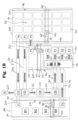
- Fig. 1A zeigt beispielhaft eine schematische Draufsicht auf ein System zum Herstellen von Betonprodukten im Gießverfahren gemäß einem ersten Ausführungsbeispiel der Erfindung.
- Fig. 1B zeigt beispielhaft eine schematische Draufsicht auf ein System zum Herstellen von Betonprodukten im Gießverfahren gemäß einem zweiten Ausführungsbeispiel der Erfindung.
- Fig. 1C zeigt beispielhaft eine schematische Draufsicht auf ein System zum Herstellen von Betonprodukten im Gießverfahren gemäß einem dritten Ausführungsbeispiel der Erfindung.
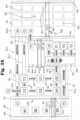
- Fig. 2A zeigt beispielhaft eine schematische Draufsicht auf ein System zum Herstellen von Betonprodukten im Gießverfahren gemäß einem vierten Ausführungsbeispiel der Erfindung.
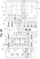
- Fig. 2B zeigt beispielhaft eine schematische Draufsicht auf ein System zum Herstellen von Betonprodukten im Gießverfahren gemäß einem fünften Ausführungsbeispiel der Erfindung.
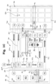
- Fig. 2C zeigt beispielhaft eine schematische Draufsicht auf ein System zum Herstellen von Betonprodukten im Gießverfahren gemäß einem sechsten Ausführungsbeispiel der Erfindung.
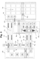
- Fig. 3 zeigt beispielhaft eine schematische Draufsicht auf ein System zum Herstellen von Betonprodukten im Gießverfahren gemäß einem siebten Ausführungsbeispiel der Erfindung.
- Fig. 4 zeigt beispielhaft eine schematische Draufsicht auf ein System zum Herstellen von Betonprodukten im Gießverfahren gemäß einem achten Ausführungsbeispiel der Erfindung.
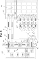
- Fig. 5 zeigt beispielhaft eine schematische Draufsicht auf ein System zum Herstellen von Betonprodukten im Gießverfahren gemäß einem neunten Ausführungsbeispiel der Erfindung.
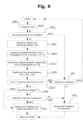
- Fig. 6 zeigt beispielhaft ein Ablaufdiagram eines Verfahrens zur Steuerung der Füllstationszufuhr in einem Herstellungssystem gemäß einem Ausführungsbeispiel der Erfindung.
- Fig. 7 zeigt beispielhaft ein Ablaufdiagram eines Verfahrens zur Steuerung eines Herstellungssystems gemäß einem Ausführungsbeispiel der Erfindung.
- Fig. 8 zeigt beispielhaft ein Ablaufdiagram eines Verfahrens zur Steuerung der Füllstationszufuhr in einem Herstellungssystem gemäß einem Ausführungsbeispiel der Erfindung.
- Fig. 9 zeigt beispielhafte Zeitverläufe von Steuerungsfunktionswerten gemäß einer Steuerung nach Figs. 7 und/oder 8.
Detaillierte Beschreibung der Figuren und bevorzugter Ausführungsbeispiele der Erfindung
-
Im Folgenden werden bevorzugte Ausführungsbeispiele der vorliegenden Erfindung unter Bezugnahme auf die beigefügten Figuren detailliert beschrieben. Die vorliegende Erfindung ist jedoch nicht auf die beschriebenen Ausführungsbeispiele beschränkt. Die vorliegende Erfindung ist durch den Umfang der Patentansprüche definiert.
-
Gleiche bzw. ähnliche Merkmale der Ausführungsbeispiele werden in den Figuren mit gleichen Bezugsziffern gekennzeichnet. Soweit Unterschiede nicht explizit angegeben sind oder aus den Figuren ersichtlich sind, ist davon auszugehen, dass die Beschreibung der Merkmale mit gleichen Bezugsziffern ein Bezug auf ein Ausführungsbeispiel ebenfalls für ein anderes Ausführungsbeispiel gilt, wobei die Beschreibung der Knappheit der Beschreibung wegen nicht mehrfach angegeben ist.
-
Weiterhin sind die Ausführungsbeispiele nicht als auf sich selbst beschränkend aufzufassen, da es möglich ist, Merkmale der nachstehend beschriebenen Ausführungsbeispiele der vorliegenden Erfindung zu kombinieren oder Ausführungsbeispiele mit Merkmalen anderer Ausführungsbeispiele zu modifizieren, um weitere Ausführungsbeispiele der vorliegenden Erfindung zu erhalten.
-
Soweit derartige Modifikationen bzw. Merkmalskombinationen in den Umfang der Ansprüche fallen, sind sie als Teil der Erfindung anzusehen und derartige Modifikationen bzw. Merkmalskombinationen weiterhin implizit als Teil der Offenbarung dieser Beschreibung anzusehen.
-
Es wird darauf hingewiesen, dass im Folgenden verwendete Begriffe, wie z.B. "Formeingabeposition" bzw. "Formausgabeposition" rein nach Blickwinkel bzw. Perspektive verwendet werden, jedoch in technischer Hinsicht in einem geschlossenen Zyklusverlauf die gleiche Funktion haben bzw. gleichwertig verwendet werden können. Eine "Formausgabeposition", bei der eine Gießform zur Ausgabe an einen weiteren Bereich bzw. an eine andere Einrichtung positioniert werden kann, würde z.B. aus Sicht des aufnehmenden Bereichs bzw. der aufnehmenden Einrichtung genauso auch als "Formeingabeposition" bezeichnet werden können.
Erstes Ausführungsbeispiel
-
Fig. 1A zeigt eine schematische Draufsicht auf ein System zum Herstellen von beispielhaft rohrförmigen Betonprodukten im Gießverfahren beispielhaft mittels beispielhaft stehenden Gießformen gemäß einem ersten Ausführungsbeispiel der Erfindung.
-
Im Allgemeinen weisen alle in dem System verwendeten Gießformen eine Außenform und ggf. eine in der Außenform positionierbare Innenform auf. Beispielhaft können Gießformen im automatisierten Umlaufzyklus jeweils eine stehende Außenform und einen in der stehenden Außenform (ggf. vertikal) angeordneten Formkern (Innenform) aufweisen. Analog können auch manuell gerüstete Gießformen eine Außenform und ggf. eine in der Außenform positionierbare Innenform aufweisen.
-
Optional können die automatisiert gerüsteten Gießformen und/oder die manuell gerüsteten Gießformen z.B. weiterhin an der Unterseite eine Untermuffe aufweisen, die z.B. als Standfläche zum Aufstellen der Gießformen dient und/oder auch zur Verriegelung der Außenform mit dem Formkern. Derartige Untermuffen können entfernbar oder fest an dem Formkern befestigt sein.
-
Ebenso können die automatisiert gerüsteten Gießformen und/oder die manuell gerüsteten Gießformen in Ausführungsbeispielen z.B. mit Obermuffen von oben verschlossen werden, wobei in weiteren Ausführungsbespielen jeweilige Fertigungsstationen vorgesehen werden können, die bevorzugt den Füllstationen nachgeordnet sein können und an denen Obermuffen (bevorzugt vollautomatisiert) an bereits mit Beton befüllten Gießformen aufgesetzt bzw. an diesen angesetzt werden können.
-
Zudem können, je nach Anforderungen des Betonprodukts, an bzw. in automatisiert gerüsteten Gießformen und/oder an bzw. in manuell gerüsteten Gießformen weitere Formteile und/oder Bewehrungen oder Bewehrungskörbe in den Gießformen vorgesehen sein. Neben Bewehrungen bzw. Bewehrungskörben können auch weitere in oder an dem fertigen Betonprodukt verbleibende Strukturteile an den Gießformen befestigt oder angebracht werden, z.B. um Steighilfen bzw. Steigbügel einzubringen oder auch Transportanker, die im Produkt verbleiben. Bei speziellen Betonprodukten können dies auch andere Einbauteile wie z.B. Ventile oder Rahmen und/oder Gitter für Straßenabläufe sein.
-
Das System zum Herstellen von Betonprodukten im Gießverfahren gemäß Fig. 1A umfasst einen automatisierten bzw. vollautomatisierten und ggf. programmgesteuerten Umlaufzyklus mit einem Fertigungsbereich mit einer Mehrzahl von automatisierten Fertigungsstationen 110, 120, 130 eines automatisierten Entschalungs- und Rüstbereichs 100 und eine Mehrzahl von automatisierten Fertigungsstationen bzw. Füllstationen F1 bis F3 eines Formfüllbereichs 300 sowie eine Formfördereinrichtung 200 mit Formförderabschnitten 211, 212, 213, 214, 241, 242, 243, 244 und 251, die für jeweilige automatisierte Produktionslinien des Umlaufzyklus zwischen den Fertigungsstationen verlaufen.
-
Die Fertigungsstationen des Systems und etwaige weitere Ausführungsbeispiele mit weiteren Konfigurationen von Fertigungsstationen werden in der weiteren Beschreibung genauer beschrieben.
-
Das System zum Herstellen von Betonprodukten im Gießverfahren gemäß Fig. 1A umfasst weiterhin einen (bevorzugt automatisierten, vollautomatisierten bzw. programmgesteuerten) Aushärtebereich 420 eines Gießformlagers 400 zum Lagern einer Mehrzahl von befüllten Gießformen und eine automatisierte Transporteinrichtung 410 auf, wobei die Transporteinrichtung 410 zum Transportieren von Gießformen von einer Formausgabeposition P5 zu Lagerpositionen in Lagerbereichen 421 im Aushärtebereich 420 und von Lagerpositionen in Lagerbereichen 421 im Aushärtebereich 420 zu einer Formeingabeposition P1 eingerichtet ist.
-
Die Formeingabeposition P1 dient hierbei beispielhaft als Übergabeposition von Gießformen aus dem Aushärtebereich 420 an den Fertigungsbereich des Umlaufzyklus und die Formeingabeposition P1 dient hierbei als Übergabeposition von Gießformen aus dem Fertigungsbereich zu dem Aushärtebereich 420.
-
Die Lagerbereiche 421 (z.B. die Bereiche der gestrichelten Rechtecke 421 im Aushärtebereich 420) können in Ausführungsbeispielen als einfache Abstellbereiche bzw. Hallenbodenbereiche einer Werkshalle ausgebildet sein. In weiteren Ausführungsbeispielen können derartige Lagerbereiche 421 auch als Klimakammern (Reifekammern) bzw. Klimabereiche bereitgestellt werden, in denen gelagerte, befüllte Gießformen zum schnelleren bzw. verbesserten Aushärten in auf gewünschte Temperaturen gebrachte Klimaumgebungen gelagert werden können (z.B. erhitzt in Bezug auf die Außentemperatur bzw. erhitzt im Vergleich zur Raumtemperatur im Fertigungsbereich). Hierbei können unterschiedliche Lagerbereiche 421 eine oder mehrere Gießformen aufnehmen und ggf. auch untereinander jeweils unterschiedliche Temperaturen bzw. zeitliche Temperaturverläufe, z.B. je nach Betonrezeptur und/oder Produkttyp bzw. -größe aufweisen.
-
Bei den Klimakammern/Reifekammern kann es sich um Einrichtungen für kontrolliertes Klima betreffend Temperatur und/oder Luftfeuchtigkeit handeln, wobei dies meist Heizeinrichtungen umfasst, z.B. insbesondere zum Heizen in der Regel zu Beginn eines Aushärtezyklus, insbesondere um die chemische Aushärtereaktion des Betons durch Wärmezufuhr zu beschleunigen. Darüber hinaus kann auch die Luftfeuchtigkeit kontrolliert werden (hohe Luftfeuchtigkeit verhindert z.B. vorteilhaft die Bildung von Rissen während des Aushärtens).
-
Bevorzugt weisen die Mehrzahl von in dem Aushärtebereich 420 gelagerten Gießformen eine Mehrzahl von Gruppen von Gießformen auf, wobei Gießformen einer Gruppe eine gleiche Formgröße aufweisen und Gießformen unterschiedlicher Gruppen unterschiedliche Formgrößen aufweisen, und wobei die in dem Aushärtebereich 420 gelagerten Gießformen nach Gruppen angeordnet sind, und Gießformen einer Gruppe in einem zusammenhängenden gemeinsamen Unterbereich des Aushärtebereichs 420 angeordnet sein können.
-
Dies ermöglicht es vorteilhaft, Gießformen mehrerer unterschiedlicher Dimensionen gleichzeitig im Aushärtebereich 420 zu lagern. Hierbei können sich somit Gießformen unterschiedlicher Dimensionen gleichzeitig im Umlauf des Herstellungssystems befinden, so dass das Herstellen von rohrförmigen Betonprodukten unterschiedlichster Größe und ggf. auch Form im gleichen Umlaufzyklus ohne das Erfordernis von Rüstzeiten oder Stillstandzeiten möglich wird, so dass ein erheblicher Effizienz- und Zeitgewinn erreichbar ist.
-
Die Transporteinrichtung 410 umfasst beispielhaft eine Greifeinrichtung 414 (Manipulator), die beispielhaft auf einer ersten Führungseinrichtung mit Führungen 413 geführt wird, welche beispielhaft auf einer dazu quer verlaufenden zweiten Führungseinrichtung mit auf Führungen 411 geführten Führungsschlitten 412 geführt wird. Die Transporteinrichtung 410 ist beispielhaft dazu eingerichtet, die Greifeinrichtung 414 mittels der Führungseinrichtungen 411, 412 und 413 im Bereich des Aushärtebereichs 420 zu verfahren und somit im gesamten Aushärtebereich 420 Gießformen mittels der Greifeinrichtung 414 aufnehmen zu können, und aufgenommene Gießformen im Bereich des Aushärtebereichs 420 zu transportieren.
-
Insbesondere ist die Transporteinrichtung 410 beispielhaft dazu eingerichtet, eine in dem Aushärtebereich 420 gelagerte Gießform automatisiert bzw. programmgesteuert aufzunehmen und automatisiert bzw. programmgesteuert zu der Formeingabeposition P1 zu transportieren bzw. eine an der Formausgabeposition P5 angeordnete Gießform automatisiert bzw. programmgesteuert aufzunehmen und automatisiert bzw. programmgesteuert zu der entsprechenden Lagerposition in einem entsprechenden Lagerbereich 421 in dem Aushärtebereich 420 zu transportieren.
-
Der Fertigungsbereich des Systems weist beispielhaft folgende Fertigungsstationen auf: Eine Entschalungsstation 110 ist beispielhaft zum automatisierten bzw. programmgesteuerten Entfernen einer Außenform von einer an der Entschalungsstation 110 positionierten Gießform und/oder zum automatisierten bzw. programmgesteuerten Entfernen eines ausgehärteten rohrförmigen Betonprodukts von einem an der Entschalungsstation 110 positionierten Formkern (Innenform) eingerichtet. Eine Reinigungsstation 120 ist beispielhaft zum automatisierten bzw. programmgesteuerten Reinigen eines an der Reinigungsstation 120 positionierten Formkerns und/oder einer an der Reinigungsstation 120 positionierten Außenform eingerichtet. Eine Formrüststation 130 ist beispielhaft zum automatisierten bzw. programmgesteuerten Zusammensetzen einer Gießform aus einer gereinigten Außenform und einem gereinigten Formkern eingerichtet, und die Füllstationen F1, F2 und F3 sind zum automatisierten bzw. programmgesteuerten Befüllen einer jeweiligen zusammengesetzten Gießform mit Beton eingerichtet.
-
Hierbei wird beispielhaft ein automatisierter Entschalungs- und Rüstbereich 100 bereitgestellt, in dem eingeführte Formen mit einem bereits ausgehärteten Betonprodukt beispielhaft entschalt (Auseinandernehmen der Gießform bzw. Entnahme des Betonprodukts) werden können, zur automatisierten Ausgabe des fertigen Betonprodukts, wobei die Formteile (Außen- und/oder Innenform) der Gießform beispielhaft nach Entnahme und Ausgabe des fertigen Betonprodukts gereinigt und zur Ausbildung einer neu gerüsteten Gießform zusammengesetzt werden können, um erneut im automatisierten bzw. programmgesteuerten Umlaufzyklus dem Füllbereich 300 zugeführt zu werden, wo Gießformen an einer jeweiligen Füllstation F1, F2 oder F3 im Gießverfahren mit Beton befüllt werden können, um dann zum Aushärten wieder dem Aushärtebereich 420 zugeführt zu werden.
-
Folglich weist der Fertigungsbereich beispielhaft eine Produktionslinie eines automatisierten bzw. programmgesteuerten Umlaufzyklus auf, der beispielhaft die automatisierten bzw. programmgesteuerten Operationen des Entschalens der Gießform (Entschalungsstation 110), des Reinigens der Gießform (Reinigungsstation 120), des Rüstens bzw. Verheiratens der gereinigten Gießform (Formrüststation 130) und des Füllens bzw. Abgießens mit Beton (Füllstationen F1 bis F3) Anordnung umfasst, wobei mit dem automatisiert gesteuerten Aushärtebereich 420 und dessen Transporteinrichtung 410 ein Closed-Loop System zur Verwendung bzw. Wiederverwendung von Gießformen im Umlaufzyklus zur Herstellung der Betonprodukte bereitgestellt werden kann.
-
Beispielhaft können z.B. Schrumpfkerne als Formkerne verwendet werden, die an der Entschalungsstation 110 geschrumpft werden, um das Betonprodukt an der Entschalungsstation 110 entfernen zu können. Weiterhin können etwaige Untermuffen fest an den Formkernen befestigt sein und in der Reinigungsstation 120 mitgereinigt werden. An der Formrüststation 130 können die Außenformen auf die Formkerne aufgestülpt werden und ggf. zudem mit etwaigen Untermuffen verriegelt werden. Jedoch können auch anderweitige Innenformen verwendet werden.
-
Die Fertigungsstationen 110 bis 130 und F1 bis F3 gemäß des Ausführungsbeispiels in Fig. 1A sind beispielhaft jeweils eingerichtet, die jeweiligen Arbeitsoperationen gleichzeitig auszuführen, so dass sich beispielhaft mehrere Gießformen gleichzeitig im Umlaufzyklus der Fertigungsstationen 110 bis 130 und F1 bis F3 befinden können, z.B. eine Gießform an der Entschalungsstation 110, eine Gießform an der Reinigungsstation 120, eine Gießform an der Formrüststation 130 und jeweilige Gießformen an den jeweiligen Füllstationen F1 bis F3.
-
Bei optionaler Bereitstellung von Zwischenpositionen könnten sich gegebenenfalls noch mehr Gießformen gleichzeitig im Umlaufzyklus der Fertigungsstationen 110 bis 130 und F1 bis F3 befinden. So können z.B. auf jeweiligen Formförderabschnitten der Formfördereinrichtung 20 weitere Gießformen befinden, z.B. in etwaigen vor, zwischen oder hinter den jeweiligen Fertigungsstationen 110 bis 120 bereitgestellten Pufferbereichen (siehe z.B. Pufferbereich 701 nach der Formrüststation 130 auf dem Formförderabschnitt 214).
-
Die Formfördereinrichtung 200 ist beispielhaft dazu eingerichtet, Gießformen von der Formeingabeposition P1 automatisiert, vollautomatisiert bzw. bevorzugt programmgesteuert zu den jeweiligen Fertigungsstationen 110 bis 130 bzw. F1 bis F3 und zwischen den jeweiligen Fertigungsstationen 110 bis 130 bzw. F1 bis F3 zu transportieren und Gießformen von den Füllstationen bzw. F1 bis F3 zu der Formausgabeposition P5 zu befördern.
-
In dem Ausführungsbeispiel gemäß Fig. 1A umfasst die Formfördereinrichtung 200 beispielhaft einen Formförderabschnitt 211 zum automatisierten Befördern einer befüllten und ausgehärteten Gießform von der Formeingabeposition P1 zu der Entschalungsstation 110, insbesondere in Bezug auf eine Gießform, die von der Transporteinrichtung 410 im Aushärtebereich 420 von einer Lagerposition eines Lagerbereichs 421 aufgenommen wurde und an der Formeingabeposition P1 positioniert bzw. abgestellt wurde. Der Formförderabschnitt 211 kann mehrere Gießformen aufnehmen und somit ggf. auch als Pufferbereich vor der Entschalungsstation 110 verwendet werden.
-
Weiterhin umfasst die Formfördereinrichtung 200 beispielhaft einen Formförderabschnitt 212 zum automatisierten Befördern einer an der Entschalungsstation 110 entschalten Gießform von der Entschalungsstation 110 zu der Reinigungsstation 120 und einen Formförderabschnitt 231 zum automatisierten Befördern eines an der Entschalungsstation 110 entnommenen, ausgehärteten Betonprodukts aus der Gießform zu einer Produktausgabeposition P2, an der fertige Betonprodukte aus dem Zyklus entnommen werden können. Der Formförderabschnitt 212 kann ggf. eine oder mehrere Gießformen aufnehmen und somit ggf. auch als Pufferbereich zwischen der Entschalungsstation 110 und der Reinigungsstation 120 verwendet werden.
-
Weiterhin umfasst die Formfördereinrichtung 200 beispielhaft einen Formförderabschnitt 213 zum automatisierten Befördern einer an der Reinigungsstation 120 gereinigten Gießform von der Reinigungsstation 120 zu der Formrüststation 130 und einen Formförderabschnitt 214 zum automatisierten Befördern einer an der Formrüststation 130 gerüsteten Form von der Formrüststation 130 zu einer Übergabeeinrichtung 310 zum Übergeben bzw. Zuführen von Gießformen an die Füllstationen F1 bis F3.
-
Der Formförderabschnitt 213 kann ggf. eine oder mehrere Gießformen aufnehmen und somit ggf. auch als Pufferbereich zwischen der Reinigungsstation 120 und der Formrüststation 130 verwendet werden. Der Formförderabschnitt 214 kann mehrere Gießformen aufnehmen und somit ggf. auch als Pufferbereich 701 zwischen der Formrüststation 130 und der Übergabeeinrichtung 310 verwendet werden.
-
In dem Ausführungsbeispiel gemäß Fig. 1A umfasst der Umlaufzyklus bzw. der Fertigungsbereich weiterhin einen automatisierten bzw. programmgesteuerten Füllbereich 300 mit beispielhaft drei parallel arbeitenden Füllstationen F1 bis F3. Der Füllbereich 300 umfasst beispielhaft eine automatisierte bzw. programmgesteuerte Übergabeeinrichtung 310, die dazu eingerichtet ist, von dem Formförderabschnitt 214 von der Rüststation 130 beförderte Gießformen aufzunehmen und automatisiert, vollautomatisiert oder bevorzugt programmgesteuert einer der Füllstationen F1 bis F3 zum Befüllen mit Beton im Gießverfahren zuzuführen.
-
Hierbei entscheidet bevorzugt eine programmgesteuerte Steuerung des Systems (nicht dargestellt) darüber, wann und an welche Füllstation F1 bis F3 eine weitere Gießform zum Befüllen mit Beton übergeben wird, bevorzugt im Umlaufzyklus in der Regel sobald eine Füllstation frei wird, wenn eine zuvor übergebene Gießform vollständig befüllt ist und abtransportiert wurde. Allerdings können für jeweilige Gießformen individuelle Gießzeiten vorgespeichert sein, und die Übergabeeinrichtung 310 kann in Ausführungsbeispielen anhand der Maßgabe gesteuert werden, auf Basis der vorgespeicherten Gießzeiten eine Reihenfolge der zu befüllenden Gießformen zu ändern.
-
In dem Ausführungsbeispiel gemäß Fig. 1A weist die Übergabeeinrichtung 310 beispielhaft einen Verschiebetisch 311 (Verschiebeschlitten) auf, der beispielhaft quer zu der Förderrichtung des Formförderabschnitts 214 verfahrbar ist, um eine von dem Formförderabschnitt 214 aufgenommene Gießform einem der Formförderabschnitte 241, 242 oder 243 zuzuführen, wobei die Formförderabschnitte 241, 242 oder 243 jeweils dazu eingerichtet sind, die jeweilige Gießform von dem Verschiebetisch 311 der jeweiligen Füllstation F1, F2 bzw. F3 zuzuführen, zum Befüllen der Gießform an der jeweiligen Füllstation F1, F2 bzw. F3.
-
Nach Befüllen der Gießformen sind die Formförderabschnitte 241, 242 oder 243 jeweils dazu eingerichtet, die jeweilige Gießform von der jeweiligen Füllstation F1, F2 bzw. F3 wieder dem Verschiebetisch 311 der Übergabeeinrichtung 310 zuzuführen, bevorzugt derart dass der Verschiebtisch 311 durch Verfahren zum Formförderabschnitt 244 die Gießform zu diesem befördern kann, wobei der Formförderabschnitt 244 dazu eingerichtet ist, die bereits befüllte Gießform von dem Verschiebetisch 311 aufzunehmen und der Formausgabeposition bzw. Zwischenposition P3 zuzuführen. Alternativ (oder zusätzlich) könnte der Formförderabschnitt 244 dazu eingerichtet sein, die bereits befüllte Gießform bereits direkt zu einer im Aushärtebereich angeordneten Ausgabeposition zuzuführen.
-
Beispielhaft ist in dem System gemäß Fig. 1A eine weitere Formeingabeposition P4 vorgesehen, von der ein weiterer Formförderabschnitt 251 die Gießformen jeweils zu der im Aushärtebereich 420 angeordneten Ausgabeposition P5 befördert, von wo die Greifereinrichtung 414 der Transporteinrichtung 410 die jeweilige Gießform aufnehmen und zu dem vorbestimmten Lagerbereich 421 im Aushärtebereich 420 transportieren kann.
-
Zur Beförderung der Gießformen zwischen der Zwischenposition P3 und der Formeingabeposition P4 ist in Fig. 1A beispielhaft eine weitere Transporteinrichtung 610 vorgesehen, um Gießformen ggf. in einem Zwischenlagerbereich 600 abstellen zu können (optional).
-
Die Transporteinrichtung 610 umfasst beispielhaft eine Greifeinrichtung 614 (Manipulator), die beispielhaft auf einer ersten Führungseinrichtung mit Führungen 613 geführt wird, welche beispielhaft auf einer dazu quer verlaufenden zweiten Führungseinrichtung mit auf Führungen 611 geführten Führungsschlitten 612 geführt wird. Die Transporteinrichtung 610 ist beispielhaft dazu eingerichtet, die Greifeinrichtung 614 mittels der Führungseinrichtungen 611, 612 und 613 im Bereich des Zwischenlagerbereichs 600 zu verfahren bzw. Gießformen mittels der Greifeinrichtung 414 aufnehmen zu können, und aufgenommene Gießformen zwischen dem Zwischenlagerbereich 600 und den jeweiligen Positionen P3 und P4 transportieren zu können.
-
Insbesondere ist die Transporteinrichtung 610 beispielhaft dazu eingerichtet, eine an der Zwischenposition P3 stehende Gießform automatisiert bzw. programmgesteuert aufzunehmen und automatisiert bzw. programmgesteuert zu der Formeingabeposition P4 oder zum Zwischenlagerbereich 600 zu transportieren bzw. eine in dem Zwischenlagerbereich 600 angeordnete Gießform automatisiert bzw. programmgesteuert aufzunehmen und automatisiert bzw. programmgesteuert zu der Formeingabeposition P4 zu transportieren.
-
Der Zwischenlagerbereich 600 kann z.B. dafür verwendet werden, Gießformen vor dem Verschließen mit Muffen nach dem Befüllen entlüften zu lassen, Gießformen manuell zu überprüfen und/oder auch Obermuffen an den Gießformen zum Verschließen der Gießformen anzubringen. Alternativ kann auch eine automatisierte bzw. programmgesteuerte Muffeneindrückstation bereitgestellt werden, die Obermuffen an den Gießformen zum Verschließen der Gießformen automatisiert anbringt.
-
Gemäß dem Ausführungsbeispiel aus Fig. 1A ist beispielhaft neben dem automatisierten Umlaufzyklus ein manueller Rüstbereich 500 bereitgestellt, an dem Gießformen bzw. auch individuelle Gießformen manuell rüstbar sind, wobei der manuelle Rüstbereich 500 beispielhaft derart in dem System integriert bzw. an diese angebunden ist, dass für das Herstellen von Betonprodukten mit manuell gerüsteten Gießformen zumindest der automatisierte Füllbereich 300 und der automatisierte Aushärtebereich 420 des Systems mitverwendet wird.
-
Hierzu umfasst der Aushärtebereich 420 weiterhin eine Formeingabeposition P6, zu der Gießformen mittels der Transporteinrichtung 410 transportiert werden können. Die Formfördereinrichtung 200 umfasst zudem beispielhaft weiterhin einen Formförderabschnitt 221 zum automatisierten bzw. programmgesteuerten Befördern von Gießformen von der Formeingabeposition P6 im Aushärtebereich 420 zu der Formeingabeposition P7 des manuellen Rüstbereichs 500.
-
Der manuelle Rüstbereich umfasst beispielhaft vier manuelle Rüststationen M1 bis M4, die jeweils dazu eingerichtet sind, dass manuelle Bediener an diesen manuelle Rüststationen M1 bis M4 Gießformen manuell rüsten können, d.h. insbesondere manuell Gießformen aus Formteilen, Außenformen, Innenformen, Muffenteilen und/oder Bewehrungsteilen zusammensetzen können. Hierfür können die Rüststationen M1 bis M4 beispielhaft manuell steuerbare Manipulatoren oder manuell steuerbare Kräne bzw. Kranarme aufweisen, um schwere Bauteile zusammenzusetzen.
-
Zudem kann jede Rüststation M1 bis M4 oder der manuelle Rüstbereich 500 einen Computer bzw. eine mit der Steuerung des Systems verbundene Steuereinrichtung umfassen, an der der Bediener jeweils bestätigen kann, wann eine Gießform an einer der Rüststationen M1 bis M4 fertig gerüstet wurde und dem automatisierten Füllbereich 300 zugeführt werden kann und ggf. auch zur Eingabe einer individuellen Gießzeit/Füllzeit der manuell gerüsteten Gießform und/oder zur Eingabe einer individuellen Betonrezeptur für das automatisierte Befüllen der manuell gerüsteten Gießform.
-
Zur Beförderung der Gießformen zwischen der Formausgabeposition P7 des manuellen Rüstbereichs 500 und der Formeingabeposition P8 des manuellen Rüstbereichs 500 ist in Fig. 1A beispielhaft eine weitere Transporteinrichtung 510 vorgesehen, um Gießformen ggf. in dem manuellen Rüstbereich 500 zu transportieren.
-
Die Transporteinrichtung 510 umfasst beispielhaft eine Greifeinrichtung 514 (Manipulator), die beispielhaft auf einer ersten Führungseinrichtung mit Führungen 513 geführt wird, welche beispielhaft auf einer dazu quer verlaufenden zweiten Führungseinrichtung mit auf Führungen 511 geführten Führungsschlitten 512 geführt wird. Die Transporteinrichtung 510 ist beispielhaft dazu eingerichtet, die Greifeinrichtung 514 mittels der Führungseinrichtungen 511, 512 und 513 im Bereich des manuellen Rüstbereichs 500 zu verfahren bzw. Gießformen mittels der Greifeinrichtung 514 aufnehmen zu können, und aufgenommene Gießformen zwischen den jeweiligen Positionen P7 und P8 und den manuellen Rüststationen M1 bis M4 transportieren zu können.
-
Insbesondere ist die Transporteinrichtung 510 beispielhaft dazu eingerichtet, eine an der Formausgabeposition P7 stehende Gießform automatisiert bzw. programmgesteuert aufzunehmen und automatisiert bzw. programmgesteuert zu einer der manuellen Rüststationen M1 bis M4 zu transportieren bzw. eine an einer der manuellen Rüststationen M1 bis M4 angeordnete Gießform automatisiert bzw. programmgesteuert aufzunehmen und automatisiert bzw. programmgesteuert zu der Formeingabeposition P8 zu transportieren.
-
Schließlich umfasst das System gemäß Fig. 1A beispielhaft weiterhin einen Formförderabschnitt 222 der Formfördereinrichtung 200 zum Befördern einer im manuellen Rüstbereich 500 manuell gerüsteten Gießform von der Formeingabeposition P8 zu der Übergabeeinrichtung 310. Hierbei kann der Formförderabschnitt 222 beispielhaft mehrere Gießformen aufnehmen und somit als Pufferbereich 702 verwendet werden, um Gießformen puffernd zwischenzulagern, bevor diese mittels der Übergabeeinrichtung 310 jeweils an eine der Füllstationen F1 bis F3 befördert werden und somit dem automatisierten Umlaufzyklus zugeführt werden.
-
Der Verschiebetisch 311 (Verschiebeschlitten) der Übergabeeinrichtung 310 ist beispielhaft dazu eingerichtet, quer zu der Förderrichtung des Formförderabschnitts 222 verfahren zu werden, um eine von dem Formförderabschnitt 222 aufgenommene Gießform einem der Formförderabschnitte 241, 242 oder 243 zuzuführen, wobei die Formförderabschnitte 241, 242 oder 243 jeweils wieder dazu eingerichtet sind, die jeweilige Gießform von dem Verschiebetisch 311 der jeweiligen Füllstation F1, F2 bzw. F3 zuzuführen, zum Befüllen der Gießform an der jeweiligen Füllstation F1, F2 bzw. F3.
-
Hierbei entscheidet bevorzugt die programmgesteuerte Steuerung des Systems (nicht dargestellt) darüber, wann und an welche Füllstation F1 bis F3 eine weitere Gießform von welchem der Formförderabschnitte 214 bzw. 222 zum Befüllen mit Beton übergeben wird, bevorzugt im Umlaufzyklus in der Regel sobald eine Füllstation frei wird, wenn eine zuvor übergebene Gießform vollständig befüllt ist und abtransportiert wurde. Insbesondere entscheidet die programmgesteuerte Steuerung des Systems (nicht dargestellt) vorzugsweise darüber, wann eine von dem manuellen Rüstbereich 500 kommende, manuell gerüstete Gießform von dem Formförderabschnitt 222 aufgenommen und durch die Übergabeeinrichtung 310 einer der Füllstationen F1 bis F3 zugeführt wird, insbesondere um eine manuell gerüstete Gießform automatisiert bzw. programmgesteuert dem Umlaufzyklus zuzuführen.
-
Hierbei kann ggf. eine Steuerung der Füllstationszufuhr in einem Herstellungssystem gemäß einem später beschriebenen beispielhaften Verfahren verwendet werden.
-
Beispielhaft kann die Steuerung in Ausführungsbeispielen dazu eingerichtet sein, die N Füllplätze (in Fig. 1A beispielhaft mit N = 3 entsprechend der Zahl der Füllstationen F1 bis F3) automatisiert zu belegen. Die Steuerung kann die Füllstationen derart mit Gießformen belegen, dass das ggf. schichtweise vorgegebene Produktionsprogramm optimiert wird. Beispielhafte Rahmenbedingungen können z.B. sein: der Steuerung können die individuellen Gießdauerzeiten je Gießform bekannt sein; das System weist N Füllstationen auf; und/oder jede Füllstation kann jede Form im System füllen. Im Normalfall können die Formen aus der automatischen Linie des Umlaufsystems bevorzugt gefüllt werden, z.B. um keinen Rückstau im getakteten Bereich der automatischen Linie zu verursachen. Es ist jedoch auch der umgekehrte Fall denkbar, bei dem bevorzugt Formen aus der manuellen Linie abgefertigt werden.
-
Beispielhaft kann der Computersteuerung des Systems die Maßgabe auferlegt werden, dass erst, wenn durch eine numerische Vorausberechnung bzw. Simulationsberechnung (z.B. auf Basis der Anzahl der Pufferplätze des Umlaufzyklus, der Gießzeiten der Gießformen und/oder der Taktzeit x des Umlaufzyklus, d. h. alle x Minuten wird eine automatisiert gerüstete Form von der Rüststation 130 bereitgestellt) berechnet werden kann, dass die automatisierte Fertigung des Umlaufzyklus nicht blockiert wird, entschieden wird, eine Form aus dem manuellen Rüstbereich zu einer der Füllstationen zu befördern bzw. dem Umlaufzyklus zuzuführen und damit den Umlaufzyklus nicht zu blockieren oder zum Halt zu bringen.
-
Hierbei können bei der Entscheidung, ob eine manuell gerüstete Gießform aus dem manuellen Rüstbereich 500 oder eine automatisiert gerüstete Gießform aus dem automatisierten Umlaufzyklus als nächstes dem Füllbereich 300 zugeführt wird, die Belegung der Pufferplätze in den Pufferbereichen 701 und/oder 702 mit in Betracht gezogen werden. Speziell kann der Puffer 701 (Fördereinrichtungsabschnitt 214) von der automatisierten Linie, aber auch der Puffer 702 von der manuellen Linie in die Betrachtung einbezogen werden.
-
Das System bzw. die Systemsteuerung kann nach einem programmierten Algorithmus jeweils die Entscheidung zu treffen, ob die nächste Form von der automatisierten Linie oder von der manuellen Linie zu den Füllstationen gebracht wird. Zum Beispiel kann auf Basis der in den Füllstationen befindlichen Formen und ihrer Restgießzeiten, sowie z.B. auf Basis der Gießzeit bzw. Fülldauer der nächsten Form in der manuellen Linie berechnet werden, ob in der automatisierten Linie im Pufferbereich 701 ein Stau entstehen würde, wenn die Form von der manuellen Linie als nächste Form in die Gießstation gebracht würde.
- 1. Praktisches Beispiel: Der Gießplatz 1 (Füllstation F1) ist momentan belegt mit Restgießzeit 5 Minuten, der Gießplatz 2 (Füllstation F2) ist momentan belegt mit Restgießzeit 7 Minuten und der Gießplatz 3 (Füllstation F3) wurde frei, d.h. es kann eine automatisierte Entscheidung getroffen werden, ob eine Form vom automatisierten Bereich aus dem Pufferbereich 701 bzw. von dem Formförderabschnitt 214 genommen wird oder ob eine Form vom manuellen Rüstbereich aus dem Pufferbereich 702 bzw. von dem Formförderabschnitt 222 genommen wird, um als nächstes mittels der Übergabeeinrichtung 310 der freien Füllstation F3 zugeführt zu werden.
Die auf Basis der momentanen Pufferbelegung im Pufferbereich 701 und der Taktzeit berechnete freie Pufferzeit bei der automatisierten Linie im Pufferbereich 701 bis zum Stillstand beträgt momentan 3 Minuten. Die Gießzeit der nächsten Form von der automatisierten Linie ist als 6 Minuten vorgespeichert und die Gießzeit der nächsten Form von der manuellen Linie ist als 12 Minuten vorgespeichert. Im Ergebnis führt dies in diesem praktischen Beispiel bevorzugt dazu, dass die Entscheidung getroffen wird, dass der freie Gießplatz der Füllstation F3 mit einer Form von der automatisierten Linie bestückt wird, da ansonsten ein Stillstand des Umlaufzyklus herbeigeführt würde. - 2. Praktisches Beispiel: Der Gießplatz 1 (Füllstation F1) ist momentan belegt mit Restgießzeit 5 Minuten, der Gießplatz 2 (Füllstation F2) ist momentan belegt mit Restgießzeit 3 Minuten und der Gießplatz 3 (Füllstation F3) wurde frei, d.h. es kann eine automatisierte Entscheidung getroffen werden, ob eine Form vom automatisierten Bereich aus dem Pufferbereich 701 bzw. von dem Formförderabschnitt 214 genommen wird oder ob eine Form vom manuellen Rüstbereich aus dem Pufferbereich 702 bzw. von dem Formförderabschnitt 222 genommen wird, um als nächstes mittels der Übergabeeinrichtung 310 der freien Füllstation F3 zugeführt zu werden. Die auf Basis der momentanen Pufferbelegung im Pufferbereich 701 und der Taktzeit berechnete freie Pufferzeit bei der automatisierten Linie im Pufferbereich 701 bis zum Stillstand beträgt momentan 8 Minuten. Die Gießzeit der nächsten Form von der automatisierten Linie ist als 6 Minuten vorgespeichert und die Gießzeit der nächsten Form von der manuellen Linie ist als 5 Minuten vorgespeichert. Im Ergebnis führt dies in diesem praktischen Beispiel bevorzugt dazu, dass die Entscheidung getroffen wird, dass der freie Gießplatz der Füllstation F3 mit einer Form von der manuellen Linie bestückt wird, da kein Stillstand des Umlaufzyklus droht.
-
Im Allgemeinen kann hierbei ein Entscheidungsalgorithmus verwendet werden, bei dem auf Basis der momentanen Pufferbelegung im Pufferbereich 701 und der Taktzeit eine freie Pufferzeit bei der automatisierten Linie im Pufferbereich 701 bis zum Stillstand berechnet werden. Wenn dann eine Füllstation frei wird, kann auf Basis der kleinsten Restgießdauer der anderen Füllstationen und der berechneten freien Pufferzeit berechnet werden, ob ein Stillstand droht, wenn die nächste Form von der manuellen Linie dem Füllbereich zugeführt wird. Ist die berechnete freie Pufferzeit z.B. kleiner oder gleich der kleinsten Restgießdauer der anderen Füllstationen ist, dann sollte die frei gewordene Füllstation direkt mit einer Gießform aus der automatisierten Linie belegt werden. Andernfalls, wenn die berechnete freie Pufferzeit z.B. größer als die kleinste Restgießdauer der anderen Füllstationen, dann kann die frei gewordene Füllstation ggf. mit einer Gießform aus der manuellen Linie belegt werden.
-
In weiteren Bespielen könnte hierbei dennoch die nächsten Form von der automatisierten Linie genommen werden, wenn diese Teil einer abzuschließenden Paketserie ist, d.h. dass z.B. mit Füllen dieser Form ein Paket einer Formserie einer Gruppe von Formen einer vorbestimmten Zahl abgeschlossen wird, wobei die Formen der Paketserie ggf. gemeinsam von der Greifereinrichtung 414 vom Formausgabeplatz P5 aufgenommen werden kann, um im Paket gemeinsam einem Lagerbereich 421 im Aushärtebereich 420 zugeführt zu werden, um gemeinsam auszuhärten (z.B. bei gleichen Produkten gleicher Größe und Betonrezeptur mit gleicher Aushärtezeit), z.B. wenn der vorgeschlagene Manipulator der Greifereinrichtung 414 für den Aushärtebereich 420 vorteilhaft mit Paketen von Formen (z.B. 3er-Paket, 4er-Paket oder 5erPaket arbeitet), könnte dann der Algorithmus darüber hinaus beispielhaft berücksichtigen, dass jeweils ein ganzes Paket (oder sogar eine ganze Serie gleichartiger Formen) bevorzugt von der automatisierten Linie in Serie (ohne Unterbrechung durch eine Form aus der manuellen Linie) abgegossen wird.
-
Die Merkmale dieser Ausführung können in weiteren Ausführungsbeispielen einzeln oder im Ganzen mit Merkmalen der vorstehend und nachstehend beschriebenen Ausführungsbeispiele kombiniert werden.
Zweites Ausführungsbeispiel
-
Fig. 1B zeigt eine schematische Draufsicht auf ein System zum Herstellen von beispielhaft rohrförmigen Betonprodukten im Gießverfahren beispielhaft mittels beispielhaft stehenden Gießformen gemäß einem zweiten Ausführungsbeispiel der Erfindung.
-
Im Unterschied zum Ausführungsbeispiel gemäß Fig. 1A ist hierbei im Bereich des Förderabschnitts der Formfördereinrichtung 200 zwischen der Formeingabeposition P6 im Aushärtebereich 420 und der Formausgabeposition P7 im manuellen Rüstbereich P7 eine weitere automatisierte bzw. programmgesteuerte Entschalungsstation 110' vorgesehen, die dazu eingerichtet ist, Gießformen, die mit dem Formförderabschnitt 221a von der Formeingabeposition P6 transportiert werden, automatisiert zu entschalen (analog zu der Entschalungsstation 110 in Fig. 1A) und fertige Betonprodukte zu entnehmen und dann über den Formförderabschnitt 231 zur Produktausgabeposition P2 zu befördern.
-
Hierbei kann somit im Ausführungsbeispiel gemäß Fig. 1B im System auch eine aus dem Aushärtebereich 420 auf dem Förderabschnitt 221a zu dem manuellen Rüstbereich 500 beförderte Gießform an der Entschalungsstation 110' automatisiert bzw. programmgesteuert entschalt werden, z.B. um einerseits die Formteile wie z.B. Außen- und Innenformen auseinanderzunehmen bzw. das fertige Betonprodukt zur Ausgabe an der Position P2 auszugeben, analog zu Gießformen im Umlaufzyklus, die mittels des Förderabschnitts 211 zu der Entschalungsstation 110 befördert werden.
-
Dies bedeutet, dass in dem System gemäß Fig. 1B beispielhaft die manuelle Linie (d.h. die Produktionslinie zu und von dem manuellen Rüstbereich 500) neben dem automatisierten Füllbereich 300 und dem automatisierten Aushärtebereich 420, wie in Fig. 1A, auch noch einen automatisierten Entschalungsbereich der Entschalungstationen 110 und 110' mitumfasst bzw. mitverwendet, und somit die Entschalung, das Befüllen und Aushärten der Gießformen der manuellen Linie, d.h. der im manuellen Rüstbereich 500 manuell gerüsteten Gießformen, vorteilhaft automatisiert bzw. programmgesteuert durchgeführt werden kann.
-
Hierbei können an den Entschalungsstationen 110 und 110' separate und unabhängig arbeitende Entschalungsmanipulatoren bereitgestellt werden. Zur vollständigen Trennung der beiden Linien können somit beispielhaft zwei Entschalmanipulatoren eingesetzt werden. Alternativ ist es auch möglich, einen einzigen Entschalmanipulator zu verwenden, der dazu eingerichtet ist, Gießformen an beiden Entschalungsstationen 110 und 110' zu entschalen. In einer bevorzugten Ausführungsform hat der (oder die) Entschalmanipulator(en jeweils) zwei, drei oder mehr Greifer: z.B. einen Greifer für Außenformen, einen Greifer für Obermuffen und/oder einen Greifer für das fertige Produkt.
-
Die Merkmale dieser Ausführung können in weiteren Ausführungsbeispielen einzeln oder im Ganzen mit Merkmalen der vorstehend und nachstehend beschriebenen Ausführungsbeispiele kombiniert werden.
Drittes Ausführungsbeispiel
-
Fig. 1C zeigt beispielhaft eine schematische Draufsicht auf ein System zum Herstellen von Betonprodukten im Gießverfahren gemäß einem dritten Ausführungsbeispiel der Erfindung.
-
Hierbei wird - wie in allen beispielhaften Ausführungsformen - bevorzugt zumindest der Aushärtebereich 420 des automatisierten Umlaufssystems auch für aus dem manuellen Rüstbereich 500 zugeführte Gießformen effizient mitbenutzt.
-
Im Gegensatz zu den vorstehend beschriebenen Ausführungsbeispielen und insbesondere im Unterschied zu dem Ausführungsbeispiel gemäß Fig. 1B wird jedoch beispielhaft in Fig. 1C eine eigene Füllstation F3 für aus dem manuellen Rüstbereich 500 zugeführte Gießformen bereitgestellt.
-
Ein Zuführförderabschnitt 222 der Fördereinrichtung 200 führt Gießformen von der Formeingabeposition P8 des manuellen Rüstbereich 500 der Füllstation F3 zu (oder wahlweise einer Mehrzahl von Füllstationen mit einer eigenen Übergabeeinrichtung analog zu den weiteren Ausführungsbeispielen), um die manuell gerüstete Gießform in der Füllstation F3 bevorzugt automatisiert mit Beton zu befüllen. Ein weiterer Förderabschnitt 223 führt beispielhaft die mit Beton befüllte Gießform von der Füllstation F3 zu einer Formausgabeposition P5' für den Aushärtebereich 420 des automatisierten Umlaufsystems zu.
-
Die Merkmale dieser Ausführung können in weiteren Ausführungsbeispielen einzeln oder im Ganzen mit Merkmalen der vorstehend und nachstehend beschriebenen Ausführungsbeispiele kombiniert werden.
Viertes Ausführungsbeispiel
-
Fig. 2A zeigt eine schematische Draufsicht auf ein System zum Herstellen von beispielhaft rohrförmigen Betonprodukten im Gießverfahren beispielhaft mittels beispielhaft stehenden Gießformen gemäß einem vierten Ausführungsbeispiel der Erfindung.
-
Im Unterschied zum Ausführungsbeispiel gemäß Fig. 1A ist hierbei im Fertigungsbereich 100 eine Förderlinie der Innenformen und eine parallel dazu verlaufende Förderlinie für Außenformen gezeigt. Hierbei werden die jeweiligen Formkerne (Innenformen) und Außenformen der Gießformen gemäß diesem Ausführungsbeispiel zwischen der Entschalungsstation 111 und der Formrüststation 130 in produktionstechnisch parallel geführten Linien befördert und in den separat bereitgestellten Reinigungsstationen 121 bzw. 122 gereinigt.
-
Eine erste Entschalungsstation 111 ist beispielhaft dazu eingerichtet, eine Außenform von Gießformen aufzunehmen und diese separat mittels des Förderabschnitts 216 der entsprechenden Außenformreinigungsstation 121 zuzuführen, wobei die jeweiligen Innenformen und das noch an den jeweiligen Innenformen angeordnete Produkt mittels des Förderabschnitts 215 der entsprechenden zweiten Entschalungsstation 112 zugeführt wird, die das Produkt aufnimmt und die Gießform abschließend entschalt.
-
In dem Ausführungsbeispiel gemäß Fig. 2A umfasst die Formfördereinrichtung 200 beispielhaft insbesondere beispielhaft einen Formförderabschnitt 211 zum automatisierten Befördern einer befüllten und ausgehärteten Gießform von der Formeingabeposition P1 zu der ersten Entschalungsstation 111.
-
Weiterhin ist die Formfördereinrichtung 200 beispielhaft dazu eingerichtet, eine an der ersten Entschalungsstation 111 entfernte Außenform mittels eines Formförderabschnitts 216 zu der Außenformreinigungsstation 121 zu befördern, einen Formkern (Innenform) mit ausgehärtetem Betonprodukt mittels eines Formförderabschnitts 215 von der ersten Entschalungsstation 111 zu der zweiten Entschalungsstation 112 zu befördern, ein an der zweiten Entschalungsstation 112 entferntes ausgehärtetes rohrförmiges Betonprodukt mittels eines Formförderabschnitts 231 zu der Produktausgabeposition P2 zu befördern (um das fertige Betonprodukt auszugeben und ggf. einer Nachbearbeitung zuzuführen), und einen Formkern (Innenform) von der zweiten Entschalungsstation 112 mittels eines Formförderabschnitts 212 zu der Formkernreinigungsstation 122 (Innenformreinigungsstation) zu befördern.
-
Weiterhin ist die Formfördereinrichtung 200 beispielhaft dazu eingerichtet, einen Formkern (Innenform) von der Formkernreinigungsstation 122 (Innenformreinigungsstation) mittels der Formförderabschnitte 213 und 218 (über eine optionale Vorrüststation 140) zu der Formrüststation 130 zu befördern, und eine Außenform von der Außenformreinigungsstation 121 mittels eines Formförderabschnitts 217 zu der Formrüststation 130 zu befördern.
-
Dies ermöglicht es vorteilhaft, die Zykluszeiten des Systems zu reduzieren, da die Reinigungsoperationen für Formkern (Innenform) und Außenformen separat und unabhängig voneinander und insbesondere gleichzeitig durchgeführt werden können.
-
Die optionale Vorrüststation 140 kann hierbei genutzt werden eine Innenform aus Teilen zusammenzusetzen, bzw. Untermuffen und Innenformen zusammenzusetzen. Alternativ oder zusätzlich kann die Vorrüststation 140 dazu genutzt werden, Bewehrungen bzw. Bewehrungskörbe an Innenformen anzusetzen bzw. einzusetzen.
-
Die Merkmale dieser Ausführung können in weiteren Ausführungsbeispielen einzeln oder im Ganzen mit Merkmalen der vorstehend und nachstehend beschriebenen Ausführungsbeispiele kombiniert werden.
Fünftes Ausführungsbeispiel
-
Fig. 2B zeigt eine schematische Draufsicht auf ein System zum Herstellen von beispielhaft rohrförmigen Betonprodukten im Gießverfahren beispielhaft mittels beispielhaft stehenden Gießformen gemäß einem fünften Ausführungsbeispiel der Erfindung.
-
Im Unterschied zum Ausführungsbeispiel gemäß Fig. 2A sind hierbei im Fertigungsbereich 100 den jeweiligen Reinigungsstationen 121 und 122 nachgelagerte, automatisierte bzw. programmgesteuerte Fertigungsstationen 151 bzw. 152 bereitgestellt, mit entsprechenden Förderabschnitten 213a und 213b bzw. 217a und 217b. Die Fertigungsstationen 151 und 152 können zum Vorrüsten von Innen- bzw. Außenformen genutzt werden, oder bevorzugt zum Vorbereiten bzw. Ölen von Innen- oder Außenformen (d.h. beispielhaft eine Außenformölungsstation 151 und/oder eine Innenformölungsstation 152)
-
Die Merkmale dieser Ausführung können in weiteren Ausführungsbeispielen einzeln oder im Ganzen mit Merkmalen der vorstehend und nachstehend beschriebenen Ausführungsbeispiele kombiniert werden.
Sechstes Ausführungsbeispiel
-
Fig. 2C zeigt eine schematische Draufsicht auf ein System zum Herstellen von beispielhaft rohrförmigen Betonprodukten im Gießverfahren beispielhaft mittels beispielhaft stehenden Gießformen gemäß einem sechsten Ausführungsbeispiel der Erfindung.
-
Im Unterschied zum Ausführungsbeispiel gemäß Fig. 2A fehlt hierbei die optionale Vorrüststation 140 und es sind zwei Außenformreinigungsstationen 121a und 121b seriell hintereinander vorgesehen, mit entsprechenden Förderabschnitten 216, 219 und 217, so dass die Reinigung der Außenformen beispielhaft an zwei hintereinander angeordneten Fertigungsstationen 121a und 121b durchgeführt werden kann.
-
Dies hat den Vorteil, dass die Linie für die Außenformen und die Linie für die Innenformen die gleiche Anzahl von Fertigungsstationen aufweist und daher jeweilige paarweise zusammengehörende Innen- und Außenformen parallel im Takt des getakteten Umlaufzyklus von Fertigungsstation zu Fertigungsstation befördert werden können, um gleichzeitig an der Formrüststation 130 antransportiert zu werden. In anderen Ausführungsbeispielen können hierbei auch unterschiedliche Zahlen von Fertigungsstationen in den parallelen Linien für die Innen- und Außenformen vorgesehen sein, wobei hierbei dann etwaige Förderabschnitte als Puffer zwischen Fertigungsstationen verwendet werden können, um Innen- und Außenformen jeweils gleichzeitig an der Formrüststation 130 anzutransportieren.
-
Die Merkmale dieser Ausführung können in weiteren Ausführungsbeispielen einzeln oder im Ganzen mit Merkmalen der vorstehend und nachstehend beschriebenen Ausführungsbeispiele kombiniert werden.
Siebtes Ausführungsbeispiel
-
Fig. 3 zeigt eine schematische Draufsicht auf ein System zum Herstellen von beispielhaft rohrförmigen Betonprodukten im Gießverfahren beispielhaft mittels beispielhaft stehenden Gießformen gemäß einem siebten Ausführungsbeispiel der Erfindung.
-
Im Unterschied zum Ausführungsbeispiel gemäß Fig. 1 ist hierbei die Übergabeeinrichtung 310 beispielhaft mit einem Doppelverschiebetisch 313 mit zwei nebeneinander angeordneten und zusammen verfahrbaren Verschiebetischen 311 und 312 vorgesehen, wobei jeder Verschiebetisch 311 bzw. 312 dazu eingerichtet ist, Gießformen von den Förderabschnitten 214 bzw. 222 aufzunehmen und den Förderabschnitten 241 bis 243 zu den Füllstationen F1 bis F3 zuzuführen bzw. von diesen nach dem Befüllen mit Beton wieder aufzunehmen. Der Verschiebetisch 311 ist zudem dazu eingerichtet, Gießformen dem Förderabschnitt 244 zur Formausgabeposition bzw. Zwischenposition P3 zuzuführen.
-
Dies hat den Vorteil, dass Zuführen von Gießstationen zu den Füllstationen und die Aufnahme von befüllten Gießformen parallelisiert werden kann und somit effizienter durchgeführt werden kann.
-
Die Merkmale dieser Ausführung können in weiteren Ausführungsbeispielen einzeln oder im Ganzen mit Merkmalen der vorstehend und nachstehend beschriebenen Ausführungsbeispiele kombiniert werden.
Achtes Ausführungsbeispiel
-
Fig. 4 zeigt eine schematische Draufsicht auf ein System zum Herstellen von beispielhaft rohrförmigen Betonprodukten im Gießverfahren beispielhaft mittels beispielhaft stehenden Gießformen gemäß einem achten Ausführungsbeispiel der Erfindung.
-
Im Unterschied zum Ausführungsbeispiel gemäß Fig. 1A sind hierbei fünf Füllstationen F1 bis F5 vorgesehen. Der Förderabschnitt 214 umfasst beispielhaft eine Formeingabeposition P3 und der Förderabschnitt 222 umfasst beispielhaft eine Formeingabeposition P12.
-
Die Formfördereinrichtung 200 umfasst zudem beispielhaft einen Formförderabschnitt 245 zum Befördern einer Gießform von der Zwischenposition P4 zu der Füllstation F1 und einen Formförderabschnitt 255 zum Befördern einer Gießform von der Füllstation F1 zu der Formausgabeposition P4' im Aushärtebereich 420, einen Formförderabschnitt 244 zum Befördern einer Gießform von der Zwischenposition P5 zu der Füllstation F2 und einen Formförderabschnitt 254 zum Befördern einer Gießform von der Füllstation F2 zu der Formausgabeposition P5' im Aushärtebereich 420, einen Formförderabschnitt 243 zum Befördern einer Gießform von der Zwischenposition P6 zu der Füllstation F3 und einen Formförderabschnitt 253 zum Befördern einer Gießform von der Füllstation F3 zu der Formausgabeposition P6' im Aushärtebereich 420, einen Formförderabschnitt 242 zum Befördern einer Gießform von der Zwischenposition P7 zu der Füllstation F4 und einen Formförderabschnitt 252 zum Befördern einer Gießform von der Füllstation F4 zu der Formausgabeposition P2' im Aushärtebereich 420, sowie einen Formförderabschnitt 241 zum Befördern einer Gießform von der Zwischenposition P8 zu der Füllstation F5 und einen Formförderabschnitt 251 zum Befördern einer Gießform von der Füllstation F5 zu der Formausgabeposition P8' im Aushärtebereich 420.
-
Die Formförderabschnitte 241 bis 245 bilden hierbei einen weiteren Pufferbereich 703, in dem jeweilige Gießformen zusätzlich zu den Pufferbereichen 701 und 702 noch individuell vor den jeweiligen Füllstationen puffernd zwischengelagert werden können.
-
Weiterhin wurde in diesem Ausführungsbeispiel als Übergabeeinrichtung statt eines Verschiebetisches beispielhaft eine Transporteinrichtung 320 vorgesehen, um Gießformen im Füllbereich 300 zu transportieren. Alternativ oder zusätzlich kann natürlich auch hierbei eine Übergabeeinrichtung mit Verschiebetisch oder Doppelverschiebetisch (oder auch Mehrfach-Verschiebetisch mit mehr als zwei Verschiebetischen) vorgesehen sein.
-
Die Transporteinrichtung 320 umfasst beispielhaft eine Greifeinrichtung 324 (Manipulator), die beispielhaft auf einer ersten Führungseinrichtung mit Führungen 323 geführt wird, welche beispielhaft auf einer dazu quer verlaufenden zweiten Führungseinrichtung mit auf Führungen 321 geführten Führungsschlitten 322 geführt wird.
-
Die Transporteinrichtung 320 ist beispielhaft dazu eingerichtet, die Greifeinrichtung 324 mittels der Führungseinrichtungen 321, 322 und 323 im Füllbereich 300 zu verfahren bzw. Gießformen mittels der Greifeinrichtung 324 aufnehmen zu können, und aufgenommene Gießformen zwischen den jeweiligen Positionen P3 bzw. P21 und P4 bis P8 transportieren zu können, um Gießformen von den Formförderabschnitten 214 bzw. 222 der jeweiligen Füllstation F1, F2, F3, F4 bzw. F5 zuzuführen, je nach Belegungssteuerung.
-
Insbesondere ist die Transporteinrichtung 320 beispielhaft dazu eingerichtet, eine an der Formausgabeposition P3 bzw. P12 stehende Gießform automatisiert bzw. programmgesteuert aufzunehmen und automatisiert bzw. programmgesteuert zu einer der Positionen P4 bis P8 zu transportieren.
-
Die Merkmale dieser Ausführung können in weiteren Ausführungsbeispielen einzeln oder im Ganzen mit Merkmalen der vorstehend und nachstehend beschriebenen Ausführungsbeispiele kombiniert werden.
Neuntes Ausführungsbeispiel
-
Fig. 5 zeigt eine schematische Draufsicht auf ein System zum Herstellen von beispielhaft rohrförmigen Betonprodukten im Gießverfahren beispielhaft mittels beispielhaft stehenden Gießformen gemäß einem neunten Ausführungsbeispiel der Erfindung.
-
Im Unterschied zum Ausführungsbeispiel gemäß Fig. 1A sind hierbei fünf Füllstationen F1 bis F5 vorgesehen. Zudem ist statt der Übergabeeinrichtung 310 mit Verschiebetisch 311 beispielhaft ein automatisiertes bzw. programmgesteuertes Förderabschnitt-Weichensystem 800 mit Weichenabschnitten 801 und 802 bereitgestellt.
-
Der Weichenabschnitt 801 ist dazu eingerichtet, die Förderabschnitte 214 und 222 weichenartig zusammenzuführen, und insbesondere durch automatisierte bzw. programmgesteuerte Weichensteuerung des Weichenabschnitts 801 jeweils Gießformen von dem Förderabschnitt 214 aus dem automatischen Umlaufzyklus oder von dem Förderabschnitt 222 aus dem manuellen Rüstbereich 500 zu dem Weichenabschnitt 802 zu befördern.
-
Die Formfördereinrichtung 200 umfasst zudem beispielhaft einen Formförderabschnitt 245 zum Befördern einer Gießform von dem Weichenabschnitt 802 zu der Füllstation F1 und einen Formförderabschnitt 255 zum Befördern einer Gießform von der Füllstation F1 zu der Formausgabeposition P3 im Aushärtebereich 420, einen Formförderabschnitt 244 zum Befördern einer Gießform von dem Weichenabschnitt 802 zu der Füllstation F2 und einen Formförderabschnitt 254 zum Befördern einer Gießform von der Füllstation F2 zu der Formausgabeposition P4 im Aushärtebereich 420, einen Formförderabschnitt 243 zum Befördern einer Gießform von dem Weichenabschnitt 802 zu der Füllstation F3 und einen Formförderabschnitt 253 zum Befördern einer Gießform von der Füllstation F3 zu der Formausgabeposition P5 im Aushärtebereich 420, einen Formförderabschnitt 242 zum Befördern einer Gießform von dem Weichenabschnitt 802 zu der Füllstation F4 und einen Formförderabschnitt 252 zum Befördern einer Gießform von der Füllstation F4 zu der Formausgabeposition P6 im Aushärtebereich 420, sowie einen Formförderabschnitt 241 zum Befördern einer Gießform von dem Weichenabschnitt 802 zu der Füllstation F5 und einen Formförderabschnitt 251 zum Befördern einer Gießform von der Füllstation F5 zu der Formausgabeposition P7 im Aushärtebereich 420.
-
Die Formförderabschnitte 241 bis 245 bilden hierbei mit dem Weichenabschnitt 802 und auch dem Weichenabschnitt 801 einen weiteren Pufferbereich 704, in dem jeweilige Gießformen zusätzlich zu den Pufferbereichen 701 und 702 noch individuell vor den jeweiligen Füllstationen bzw. auf den Weichenabschnitten 801 bzw. 802 puffernd zwischengelagert werden können.
-
Der Weichenabschnitt 802 ist dazu eingerichtet, den Weichenabschnitt 801 und die Förderabschnitte 241 bis 245 weichenartig zusammenzuführen, und insbesondere durch automatisierte bzw. programmgesteuerte Weichensteuerung des Weichenabschnitts 802 jeweils Gießformen von dem Weichenabschnitt 801 zu jeweils einen der Formförderabschnitte 241 bis 245 zu befördern.
-
Die Merkmale dieser Ausführung können in weiteren Ausführungsbeispielen einzeln oder im Ganzen mit Merkmalen der vorstehend und nachstehend beschriebenen Ausführungsbeispiele kombiniert werden. Insbesondere können der Weichenabschnitt 801 und/oder der Weichenabschnitt 802 einzeln oder zusammen in jedem der anderen Ausführungsbeispiele alternativ oder zusätzlich vorgesehen sein, z.B. als Kombination eines Verschiebetisches und/oder einer Transporteinrichtung gemäß einem der vorstehenden Ausführungsbeispiele mit einem Weichenabschnitt 801, oder als Kombination eines Verschiebetisches und/oder einer Transporteinrichtung gemäß einem der vorstehenden Ausführungsbeispiele mit einem Weichenabschnitt 802.
Systemsteuerung
-
Im Folgenden werden Funktionssteuerungen und Systemsteuerungen bzw. Belegungssteuerungen in einem Herstellungssystem beschrieben, wobei das System gemäß einem der vorstehenden Ausführungsmerkmale realisiert sein kann oder als Kombination von Merkmalen der vorstehenden Ausführungsmerkmale. Die folgenden Ablaufdiagramme können einer Programmsteuerung entsprechen bzw. einem Programmablauf einer programmgesteuerten Steuerung entsprechen. Derartige Steuerungsabläufe können von einem handelsüblichen Computer mit CPU bzw. einem oder mehreren Prozessoren oder auch mit internem oder externen Speichermedien durchgeführt werden, die entsprechend programmiert sind.
-
Fig. 6 zeigt beispielhaft ein Ablaufdiagram eines Verfahrens zur Steuerung der Füllstationszufuhr in einem Herstellungssystem gemäß einem Ausführungsbeispiel der Erfindung.
-
In einem System mit einer oder mehrerer Füllstationen (z.B. F1 bis F3 oder F1 bis F5) wird in einem Schritt S601 überprüft, bestimmt bzw. detektiert, ob eine der Füllstationen frei ist bzw. frei geworden ist. Eine Füllstation wird frei bzw. gilt als frei geworden, z.B. wenn eine dort gegossene Gießform bzw. befüllte Gießform vollständig mit fließfähigem Beton befüllt wurde, d.h. insbesondere wenn die Restgießzeit abgelaufen ist und das Befüllen mit Beton z.B. automatisiert gestoppt wird und die befüllte Gießform abtransportiert wird, um dem Aushärtebereich 420 zugeführt zu werden. Falls der Schritt NEIN ergibt (d.h. wenn alle Füllstationen besetzt bzw. belegt sind und jeweils Gießformen befüllt werden), dann wird der Vorgang so lange wiederholt, bis Schritt S601 JA ergibt und eine Füllstation frei geworden ist.
-
Im Schritt S602 wird überprüft, bestimmt bzw. detektiert, ob eine manuelle gerüstete Gießform verfügbar ist, d.h. z.B. ob eine manuelle gerüstete Gießform von dem manuellen Rüstbereich 500 zur Übergabeeinrichtung angefördert wurde bzw. im Pufferbereich 702 oder 703 auf automatisierte Befüllung wartet. Falls Schritt S602 NEIN ergibt, wenn keine manuell gerüstete Gießform zum Befüllen vorgehalten wird, dann wird in einem Schritt S609 überprüft, bestimmt bzw. detektiert, ob eine automatisiert gerüstete Gießform (sog. Zyklusform) verfügbar ist, d.h. z.B. ob eine automatisiert gerüstete Gießform von dem Fertigungsbereich 100 zur Übergabeeinrichtung angefördert wurde bzw. im Pufferbereich 701 auf automatisierte Befüllung wartet.
-
Falls Schritt S609 NEIN ergibt, wird erneut Schritt S601 durchgeführt. Falls Schritt S609 JA ergibt, wird die nächste verfügbare Zyklusform in Schritt S610 von dem Pufferbereich 701 aus der frei gewordenen Füllstation zugeführt, um dort automatisiert mit gießfähigem Beton befüllt zu werden. Die Steuerung steuert hierbei den Schritt S610, in dem die frei gewordene Füllstation mit der verfügbaren Zyklusform belegt wird. Hierzu kann die Steuerung die vorbestimmte Füllzeit und/oder die vorbestimmte Betonrezeptur an der Füllstation steuern, ggf. auf Basis von Schichtdaten bzw. Gießformdaten, die an der Steuerung hinterlegt sind oder einzugeben sind.
-
Falls Schritt S602 JA ergibt, wenn also eine manuell gerüstete Gießform zum Befüllen vorgehalten wird, dann wird in einem Schritt S603 berechnet, überprüft, bestimmt bzw. detektiert, ob eine Einbringfrequenz (z.B. in Einheiten der Anzahl eingebrachter manuell gerüsteter Formen pro Zeiteinheit) von manuell gerüsteten Gießformen größer als ein erster Grenzwert ist, und wenn der erste Grenzwert von der ermittelten Einbringfrequenz überschritten wird (Schritt S603 ergibt JA), wird erneut Schritt S609 durchgeführt und insbesondere wird die manuell gerüstete Form momentan noch nicht einer der Füllstationen zugeführt.
-
Hierbei kann die Einbringfrequenz eine Größe sein, die direkt oder indirekt angeben kann, wie viele manuell gerüstete Formen in einem bestimmten vergangenen Zeitintervall bzw. im Durchschnitt über eine vorbestimmte Zeitdauer in den Umlaufzyklus bzw. in den Füllbereich.eingebracht wurden.
-
Der erste Grenzwert kann hierbei vorzugsweise derart vorbestimmt sein, dass während einer bestimmten Zeitdauer, wie z.B. im Laufe der gegenwärtigen Schicht, garantiert werden kann, dass der automatisierte Umlaufzyklus nicht anhalten muss, oder zumindest eine Wahrscheinlichkeit, dass der Umlaufzyklus im Laufe der Schicht bzw. Zeitdauer anhalten muss, unter einem Grenzwert liegt, wenn die Einbringfrequenz der manuell gerüsteten Gießformen unter dem ersten Grenzwert bleibt.
-
Praktisches Beispiel: Bei einer Schichtdauer T mit einer Taktzeit T1 (bzw. durchschnittlichen Taktzeit T1) im automatisierten Umlaufzyklus (d.h. wenn exakt oder durchschnittlich jeweils nach jeder Zeitdauer T1 eine weitere Zyklusform von der Formrüststation 130 an den Pufferbereich 701 übergeben wird) sei angenommen, dass das System N > 0 Füllstationen umfasst und die (ggf. durchschnittliche) Gießzeit der Zyklusformen T2 beträgt, die (ggf. durchschnittliche) Gießzeit der manuell gerüsteten Gießformen T3 beträgt und die Zeiten T1, T2 und T3 jeweils viel kleiner sind als die Schichtdauer T (z.B. T1, T2 und T3 jeweils kleiner 20 min und die Schichtdauer T größer 2 bis 8 Stunden).
-
Somit beträgt die Anzahl der in der Schichtdauer T bereitgestellten Zyklusformen ca. T/T1 bei einer (ggf. durchschnittlichen) (Zuführ-)Frequenz von 1/T1, und die Anzahl der gießbaren Zyklusformen beträgt in der Schichtdauer T ca. (N × T)/T2 bei einer (ggf. durchschnittlichen) (Gieß-)Frequenz von N/T2. Um sicherzustellen, dass der Zyklus nicht unterbrochen werden muss, sollte die Zahl N der Füllstationen bevorzugt gewählt sein, derart, dass T/T1 kleiner ist, als (N × T)/T2 (d.h. dass die Anzahl der bereitgestellten Zyklusformen kleiner ist, als die Anzahl der im gleichen Zeitraum T gießbaren Zyklusformen), bzw. die (ggf. durchschnittliche) Frequenz 1/T1 kleiner ist als die (ggf. durchschnittliche) Frequenz N/T2. Insbesondere sollte die Zahl N der Füllstationen bevorzugt derart gewählt sein, dass N > T2/T1.
-
Somit werden allerdings potentiell T/T1 Zyklusformen während der Schicht bereitgestellt (und gegossen), wobei eigentlich (N × T)/T2 > T/T1 Zyklusformen gegossen werden könnten, so dass im Durchschnitt mit einer Gesamtstillstandzeit an den Füllstationen des Füllbereichs in Höhe von T × [1-(T2/(N × T1))] gerechnet werden kann, da in der Schicht T im Durchschnitt ca. [((N × T)/T2) - (T/T1)] mehr Zyklusformen gegossen werden könnten, als vom Umlaufzyklus bereitgestellt und gegossen werden. Der Bruchteil der Schichtdauer T, in der die Füllstationen bzw. zumindest jeweils eine der Füllstationen erwartungsmäßig unbenutzt bleiben sollte(n), beträgt somit ca. [1 - (T2/(N × T1))], so dass dies einen Maximalwert eines potentiellen Freiraums für das Füllen/Gießen von manuell gerüsteten Gießformen ermöglicht, ohne einen Stillstand des Umlaufzyklus bzw. des Takts der Fertigungsstationen im Fertigungsbereich 100 zu verursachen.
-
Weiterhin beträgt die (ggf. durchschnittliche) Gießfrequenz der manuell gerüsteten Stationen potentiell N/T3, so dass in der maximal verfügbaren Zeit T × [1- (T2/(N × T1))] pro Schichtdauer T maximal (T/T3) × [N - (T2/T1)] manuell gerüstete Formen gegossen werden können, d.h. im Durchschnitt mit einer maximalen Einbringfrequenz von [N - (T2/T1)]/T3 (als Maximalwert des ersten Grenzwerts). Im Ergebnis können somit in der Schichtdauer T maximal (T/T3) × [N - (T2/T1)] mittels der Übergabeeinrichtung in den Umlaufzyklus eingebracht werden, ohne einen Stillstand des Umlaufzyklus bzw. des Takts der Fertigungsstationen im Fertigungsbereich 100 zu verursachen. Aus Sicherheitsgründen kann der erste Grenzwert ggf. kleiner der maximalen Einbringfrequenz von [N - (T2/T1)]/T3 eingestellt sein und in der Steuerung hinterlegt bzw. berechnet werden, und/oder auch an den manuellen Rüststationen an etwaigen Bildschirmen dargestellt werden.
-
Alternativ oder zusätzlich zu dem vorstehend beschriebenen Schritt S603 kann in einem weiteren Schritt S604 überprüft werden, ob die Dauer zur nächsten freiwerdenden Füllstation (d.h. z.B. die minimale Restgießzeit der momentan füllenden Füllstationen) größer ist, als eine vorbestimmte Pufferzeit, die z.B. auf Basis der Zeiten T1 und/oder T2 vorbestimmbar ist oder auf Basis der momentanen Pufferbelegung im Pufferbereich 701 und auf Basis der Zeiten T1 und T2 ermittelbar ist, auf Basis der Maßgabe, dass die Dauer zur nächsten freiwerdenden Füllstation kleiner ist, als die Zeit zur Maximalbelegung im Pufferbereich 701. Hierbei ist es z.B. in einfachen Ausführungsbeispielen möglich, die Pufferzeit zu berechnen, als Pufferzeit = T1 oder als n × T1 mit n > 1.
-
Falls zumindest einer der Schritte S603 bzw. S604 JA ergibt, wird Schritt S609 durchgeführt, um eine etwaige verfügbare Zyklusform statt der manuell gerüsteten Gießform dem Füllbereich bzw. der freigewordenen Füllstation zuzuführen.
-
Falls beide Schritte S603 bzw. S604 NEIN ergeben, dann wird in Schritt S605 überprüft, bestimmt bzw. detektiert, ob eine automatisiert gerüstete Gießform (sog. Zyklusform) verfügbar ist, d.h. z.B. ob eine automatisiert gerüstete Gießform von dem Fertigungsbereich 100 zur Übergabeeinrichtung angefördert wurde bzw. im Pufferbereich 701 auf automatisierte Befüllung wartet. Falls Schritt S605 NEIN ergibt, dann kann direkt in Schritt S608 die verfügbare manuell gerüstete Gießform der frei gewordenen Füllstation zugeführt werden.
-
Die nächste verfügbare manuell gerüstete Gießform wird in Schritt S608 von dem Pufferbereich 702 aus der frei gewordenen Füllstation zugeführt, um dort automatisiert mit gießfähigem Beton befüllt zu werden. Die Steuerung steuert hierbei den Schritt S608, in dem die frei gewordene Füllstation mit der verfügbaren Gießform belegt wird. Hierzu kann die Steuerung die vorbestimmte Füllzeit und/oder die vorbestimmte Betonrezeptur an der Füllstation steuern, ggf. auf Basis von Schichtdaten bzw. Gießformdaten, die an der Steuerung hinterlegt sind oder einzugeben sind, oder anhand von Daten, die ein Bediener beim manuellen Rüsten der Gießform an der jeweiligen Rüststation M1 bis M4 des manuellen Rüstbereichs 500 an einer Computersteuerung bzw. Eingabestation eingegeben hat.
-
Falls Schritt S605 JA ergibt, kann optional in einem oder zwei weiteren Schritten noch überprüft, bestimmt bzw. detektiert werden, ob dennoch die verfügbare Zyklusform statt der verfügbaren manuell gerüsteten Gießform dem Füllbereich 300 bzw. der freigewordenen Füllstation zugeführt wird.
-
Beispielhaft kann in einem Schritt S606 überprüft, bestimmt bzw. detektiert werden, ob eine Zykluspufferzonenbelegung größer als ein zweiter Grenzwert ist, insbesondere z.B. um festzustellen, ob noch mindestens eine vorbestimmbare Anzahl von K > 0 freien Pufferzonenplätzen im Pufferbereich 701 verfügbar ist bzw. ob die Anzahl der belegten Pufferzonenplätzen im Pufferbereich 701 einen Maximalwert bzw. einen Maximalprozentsatz in Bezug auf die Gesamtpufferplatzzahl nicht überschreiten.
-
In einem weiteren optionalen Schritt S608 kann bevorzugt geprüft werden, ob die verfügbare Zyklusform die letzte (und/oder vorletzte und/oder vorvorletzte) Gießform einer Zyklusform-Paketserie ist, d.h. um die bereits angefangene Paketserie nicht zu unterbrechen und bevorzugt abzuschließen, bevor die manuell gerüstete Gießform den Füllstationen zugeführt wird.
-
Nur wenn beide optionale Schritte S606 und S607 NEIN ergeben, wird Schritt S608 ausgeführt, und die verfügbare manuell gerüstete Gießform wird von dem Pufferbereich 702 aus der frei gewordenen Füllstation zugeführt, um dort automatisiert mit gießfähigem Beton befüllt zu werden. Ansonsten wird dennoch statt der manuell gerüsteten Gießform die verfügbare Zyklusform der freigewordenen Füllstation zugeführt (Schritt S610).
-
Fig. 7 zeigt beispielhaft ein Ablaufdiagram eines Verfahrens zur Steuerung eines Herstellungssystems gemäß einem Ausführungsbeispiel der Erfindung.
-
Im Schritt S701 werden vor Beginn der Schicht und vor Aktivierung des automatisierten Umlaufzyklus Zyklusschichtplandaten einer Schicht mit t0 (oder 0) kleiner gleich t kleiner gleich tE geladen. Die Schichtplandaten können von einem Schichtleiter vorgespeichert werden oder von einer automatisierten Steuerung eingegeben werden. Die Schichtplandaten enthalten bevorzugt Daten, die die Gesamtschichtdauer, die Anzahl N der verfügbaren Füllstationen, der Taktzeit(en), der gießbaren Zyklusformen ggf. mit deren vorbestimmter Reihenfolge, der jeweiligen Gießzeiten und/oder Gießvolumen und/oder ggf. deren vorbestimmten Betonrezepturen angeben.
-
Im Schritt S702 wird aus den geladenen Zyklusschichtplandaten die Taktzeit T im Zyklus (bzw. bei unterschiedlichen Taktzeiten über die Schichtdauer der zeitliche Verlauf der Taktzeit T(t)) bestimmt.
-
Im Schritt S703 wird eine zeitlich variable Steuerungsfunktion Z(t) bzw. zeitlich veränderliche Steuerungsfunktionswerte Z(t) der Pufferzonenzufuhr-Gesamtzahl Z in Abhängigkeit der Zeit t während der Schicht bestimmt. Dies entspricht der Gesamtzahl Z der aus dem automatisierten Fertigungsbereich dem Pufferbereich 701 zugeführten Zyklusformen bis zum Zeitpunkt t seit Schichtbeginn (ggf. plus die bereits zu Schichtbeginn im Pufferbereich 701 angeordneten Gießformen/Zyklusformen aus der vorangegangenen Schicht). Die Steuerungsfunktionswerte Z(t) der Pufferzonenzufuhr-Gesamtzahl Z in Abhängigkeit der Zeit t während der Schicht wachsen monoton mit der Zeit t, da die dem Pufferbereich 701 zugeführte Zahl ohne Stillstand des Umlaufzyklus nach jeder Taktzeit um die Zahl Eins anwächst.
-
Fig. 9 zeigt beispielhafte Zeitverläufe von Steuerungsfunktionswerten gemäß einer Steuerung nach Figs. 7 und/oder 8.
-
Hierbei zeigt der obere Verlauf eine beispielhafte zeitliche Entwicklung der Pufferzonenzufuhr-Gesamtzahl Z(t) in Abhängigkeit der Zeit t während der Schicht ab einem beispielhaften Zeitpunkt t0 mit einer beispielhaften Anfangszahl von z0 im Pufferbereich 701 stehenden Gießformen. Die Taktzeit T ist beispielhaft konstant und nach jeder Zeit t wächst Z(t) um die Zahl Eins.
-
In Schritt S704 in Fig. 7 wird die Anzahl N der verfügbaren Füllstationen bestimmt und aus den Schichtplandaten werden in Schritt S705 die jeweiligen Füllzeiten x_i der Zyklusformen i (mit beispielhaft vorbestimmter Reihenfolge i=1, 2, 3, ...) ausgelesen bzw. bestimmt. Unter der Annahme, dass die N Füllstationen jeweils immer wieder und fortlaufend mit Zyklusformen i bestückt werden, sobald eine Füllstation frei geworden ist, wird in Schritt S706 eine Restfüllzeitfunktion D(t) in Abhängigkeit von N und der jeweiligen Füllzeiten x_i als Funktion der Zeit ermittelt, wobei die Restfüllzeitfunktion D(t) bevorzugt jeweils zur Zeit t die Dauer zur nächsten freiwerdenden Füllstation angibt. Diese Restfüllzeitfunktion D(t) sinkt jeweils monoton mit der Zeit t und springt bei jedem Nullpunkt auf x_i wenn dann die nächste Zyklusform i an der frei gewordenen Füllstation zugeführt wird.
-
Hierbei können jeweils anhand der entsprechenden Füllzeiten x_i und dem Zeitpunkt der Belegung einer Füllstation mit der jeweiligen Zyklusform i für jede Füllstation j (j =1, 2, ..., N) eine Restgießzeit α_j bzw. α_j(t) ermittelt werden, wobei die Restfüllzeitfunktion D(t) jeweils durch die minimale Restgießzeit α_j, bis die nächste Füllstation frei wird, gegeben ist. Somit ist die Restfüllzeitfunktion D(t) gegeben als D(t) = min(α_1, ..., α_j, ..., α_N).
-
In Fig. 9 zeigt der zweite Verlauf von oben eine beispielhafte zeitliche Entwicklung der Restfüllzeitfunktion D(t) in Abhängigkeit der Zeit t während der Schicht ab einem beispielhaften Zeitpunkt t0. Zu jedem Zeitpunkt, zu dem die Restfüllzeitfunktion D(t) auf Null fällt, ist eine Gießform vollständig befüllt und eine nächste Gießform kann der frei gewordenen Füllstation zugeführt werden, wobei zu diesem Zeitpunkt die Restfüllzeitfunktion D(t) auf den Wert springt, der der Restfüllzeit an der nächsten frei werdenden Füllstation entspricht.
-
In Schritt S708 in Fig. 7 wird eine Pufferzonenabführ-Gesamtzahl G(t) in Abhängigkeit des Verlaufs der Restfüllzeitfunktion D(t) bestimmt. Die Pufferzonenabführ-Gesamtzahl G(t) entspricht der Gesamtzahl G der aus dem Pufferbereich 701 dem Füllbereich zugeführten Zyklusformen bis zum Zeitpunkt t seit Schichtbeginn (ggf. plus die bereits zu Schichtbeginn dem Pufferbereich 701 in den Füllbereich verbrachten Formen). Die Steuerungsfunktionswerte G(t) der Pufferzonenabführ-Gesamtzahl G in Abhängigkeit der Zeit t während der Schicht wachsen monoton mit der Zeit t, da die aus dem Pufferbereich 701 entnommene Zahl jedes Mal dann um die Zahl Eins anwächst, wenn die Restfüllzeitfunktion D(t) auf Null fällt, und eine Gießform vollständig befüllt ist und eine nächste Gießform der frei gewordenen Füllstation zugeführt werden kann.
-
Hierbei zeigt der dritte Verlauf von oben in Fig. 9 eine beispielhafte zeitliche Entwicklung der Pufferzonenabführ-Gesamtzahl G(t) in Abhängigkeit der Zeit t während der Schicht ab einem beispielhaften Zeitpunkt t0 mit einer beispielhaften Anfangszahl von g0. Die Steuerungsfunktionswerte G(t) der Pufferzonenabführ-Gesamtzahl G wachsen jedes Mal dann um die Zahl Eins, wenn die Restfüllzeitfunktion D(t) auf Null fällt.
-
In Schritt S709 in Fig. 7 wird eine Pufferzonenbelegungszahl P(t) in Abhängigkeit von der Zeit t bestimmt, auf Basis der Differenz zwischen Z(t) und G(t) gemäß den Schritten S706 und S708. Pufferzonenbelegungszahl P(t) entspricht hierbei beispielhaft der Anzahl der in dem Pufferbereich 701 zwischengelagerten Gießformen aus dem automatisierten Umlaufzyklus.
-
Hierbei zeigt der untere Verlauf in Fig. 9 eine beispielhafte zeitliche Entwicklung der Pufferzonenbelegungszahl P(t) in Abhängigkeit der Zeit t während der Schicht ab einem beispielhaften Zeitpunkt t0 mit einer beispielhaften Anfangszahl von p0 der zu dem Zeitpunkt t0 im Pufferbereich 701 befindlichen Gießformen. Die Steuerungsfunktionswerte P(t) der Pufferzonenbelegungszahl P wachsen jedes Mal dann um die Zahl Eins, wenn die Pufferzonenzufuhr-Gesamtzahl Z(t) um die Zahl Eins anwächst und fallen jedes Mal dann um die Zahl Eins, wenn die Pufferzonenabführ-Gesamtzahl G(t) um die Zahl Eins anwächst.
-
In Schritt S710 in Fig. 7 wird ermittelt, geprüft bzw. detektiert, ob die ermittelte Pufferzonenbelegungszahl P(t) für den gesamten relevanten Zeitraum, z.B. in der Schicht von Schichtanfang bis Schichtende bzw. von t0 bis tE, eine maximale Pufferzonenbelegungszahl P_MAX überschreitet bzw. ob die ermittelte Pufferzonenbelegungszahl P(t) für den gesamten relevanten Zeitraum, z.B. in der Schicht von Schichtanfang bis Schichtende bzw. von t0 bis tE, kleiner oder gleich der maximalen Pufferzonenbelegungszahl P_MAX bleibt, d.h. ob P(t) ≤ P_MAX für alle t ist.
-
Falls Schritt S710 NEIN ergibt, d.h. wenn zumindest zu einem Zeitpunkt die Pufferzonenbelegungszahl P die maximale Pufferzonenbelegungszahl P_MAX überschreitet, muss mit einem zumindest potentiellen Zyklusstop aufgrund einer Vollbelegung des verfügbaren Pufferplatzes gerechnet werden, und in Schritt S711 wird eine Warnungsmeldung ausgegeben. Dies kann die Steuerung beenden oder alternativ beispielhaft dazu führen, dass in einem optionalen weiteren Schritt S712 überprüft bzw. bestimmt wird, ob in der Schicht ein Zyklusstop tolerierbar ist, z.B. auf Basis von Voreinstellungen in den Zyklusschichtplandaten.
-
Falls Schritt S712 oder Schritt S710 JA ergibt, wird in Schritt S713 die Zeit auf Reset t0 gesetzt und der Umlaufzyklus wird automatisiert gestartet, d.h. im Fertigungsbereich 100 und im Füllbereich 300 werden automatisiert Zyklusformen bearbeitet und von Fertigungsstation zu Fertigungsstation geführt.
-
Solange die Zeit t kleiner ist als die Schichtdauer tE (Schritt S716 ergibt NEIN) werden dann die Schritte S714 der Steuerung der Zyklusfunktionen (z.B. Förderabschnitte, Taktzyklen, Fertigungsstationen) und S715 der Steuerung der Füllstationszufuhr mittels der Übergabeeinrichtung (z.B. gemäß Fig. 6 oder Fig. 8) gesteuert.
-
Fig. 8 zeigt beispielhaft ein Ablaufdiagram eines Verfahrens zur Steuerung der Füllstationszufuhr in einem Herstellungssystem gemäß einem Ausführungsbeispiel der Erfindung.
-
In einem System mit einer oder mehrerer Füllstationen (z.B. F1 bis F3 oder F1 bis F5) wird in einem Schritt S801 überprüft, bestimmt bzw. detektiert, ob eine der Füllstationen frei ist bzw. frei geworden ist. Eine Füllstation wird frei bzw. gilt als frei geworden, z.B. wenn eine dort gegossene Gießform bzw. befüllte Gießform vollständig mit fließfähigem Beton befüllt wurde, d.h. insbesondere wenn die Restgießzeit abgelaufen ist und das Befüllen mit Beton z.B. automatisiert gestoppt wird und die befüllte Gießform abtransportiert wird, um dem Aushärtebereich 420 zugeführt zu werden. Falls der Schritt NEIN ergibt (d.h. wenn alle Füllstationen besetzt bzw. belegt sind und jeweils Gießformen befüllt werden), dann wird der Vorgang so lange wiederholt, bis Schritt S801 JA ergibt und eine Füllstation frei geworden ist.
-
Im Schritt S802 wird überprüft, bestimmt bzw. detektiert, ob eine manuelle gerüstete Gießform verfügbar ist, d.h. z.B. ob eine manuelle gerüstete Gießform von dem manuellen Rüstbereich 500 zur Übergabeeinrichtung angefördert wurde bzw. im Pufferbereich 702 oder 703 auf automatisierte Befüllung wartet. Falls Schritt S802 NEIN ergibt, wenn keine manuell gerüstete Gießform zum Befüllen vorgehalten wird, dann wird in einem Schritt S811 überprüft, bestimmt bzw. detektiert, ob eine automatisiert gerüstete Gießform (sog. Zyklusform) verfügbar ist, d.h. z.B. ob eine automatisiert gerüstete Gießform von dem Fertigungsbereich 100 zur Übergabeeinrichtung angefördert wurde bzw. im Pufferbereich 701 auf automatisierte Befüllung wartet.
-
Falls Schritt S811 NEIN ergibt, wird erneut Schritt S801 durchgeführt. Falls Schritt S811 JA ergibt, wird die nächste verfügbare Zyklusform in Schritt S812 von dem Pufferbereich 701 aus der frei gewordenen Füllstation zugeführt, um dort automatisiert mit gießfähigem Beton befüllt zu werden. Die Steuerung steuert hierbei den Schritt S812, in dem die frei gewordene Füllstation mit der verfügbaren Zyklusform belegt wird. Hierzu kann die Steuerung die vorbestimmte Füllzeit und/oder die vorbestimmte Betonrezeptur an der Füllstation steuern, ggf. auf Basis von Schichtdaten bzw. Gießformdaten, die an der Steuerung hinterlegt sind oder einzugeben sind.
-
Falls Schritt S802 JA ergibt, wenn also eine manuell gerüstete Gießform zum Befüllen vorgehalten wird, dann wird in einem Schritt S803 eine Füllzeit bzw. Gießdauer y dieser manuell gerüsteten Form ermittelt, z.B. anhand von Daten, die vom manuellen Bediener an der manuellen Rüststation eingegeben wurden, oder anhand von Daten, die auf Basis eines Innenvolumens der manuell gerüsteten Gießform berechnet werden.
-
In einem Schritt S804 wird auf Basis der Anzahl N der verfügbaren Füllstationen, der ermittelten Gießdauer y dieser manuell gerüsteten Form und der in Schichtplandaten angegebenen Füllzeiten x_i der Zyklusformen i (mit beispielhaft vorbestimmter Reihenfolge i=1, 2, 3, ...) eine potentielle Restfüllzeitfunktion D'(t) ab dem gegenwärtigen Zeitpunkt t bis zum Schichtende oder bis zum Ablauf einer vorbestimmten Zeitdauer T mit Endzeit tE berechnet, unter der Annahme, dass die manuelle gerüstete Gießform an die nächste frei werdenden Füllstation befördert und dieser zum Befüllen zugeführt wird. Dies entspricht im Wesentlichen einer berechneten Simulation der Restfüllzeitfunktion D'(t) unter der Annahme, dass die nächste frei werdende Füllstation anstatt mit der nächsten Zyklusform stattdessen mit der manuell gerüsteten Gießform belegt würde.
-
Analog zu den Schritten S706 bis S710 wird in Schritt S805 unter der Annahme, dass die N Füllstationen zunächst mit der manuell gerüsteten Gießform und dann jeweils immer wieder und fortlaufend mit Zyklusformen i bestückt werden, sobald eine Füllstation frei geworden ist, wird in Schritt S805 die Restfüllzeitfunktion D'(t) in Abhängigkeit von N und der jeweiligen Füllzeiten y und x_i als Funktion der Zeit ermittelt, wobei die Restfüllzeitfunktion D(t) wieder bevorzugt jeweils zur Zeit t die Dauer zur nächsten freiwerdenden Füllstation angibt.
-
In Schritt S805 in Fig. 8 wird die potentielle Pufferzonenabführ-Gesamtzahl G'(t) in Abhängigkeit des Verlaufs der Restfüllzeitfunktion D'(t) bestimmt, und in Schritt S806 in Fig. 8 wird die potentielle Pufferzonenbelegungszahl P'(t) in Abhängigkeit von der Zeit t bestimmt, auf Basis der Differenz zwischen Z(t) und G'(t) gemäß den Schritten S706 und S805.
-
In Schritt S807 in Fig. 8 wird ermittelt, geprüft bzw. detektiert, ob die ermittelte potentielle Pufferzonenbelegungszahl P'(t) für den gesamten relevanten Zeitraum, z.B. bis Schichtende bzw. bis tE, die maximale Pufferzonenbelegungszahl P_MAX überschreitet bzw. ob die ermittelte Pufferzonenbelegungszahl P'(t) für den gesamten relevanten Zeitraum kleiner oder gleich der maximalen Pufferzonenbelegungszahl P_MAX bleibt, d.h. ob P'(t) ≤ P_MAX für alle t ist.
-
Falls Schritt S807 NEIN ergibt und eine Zyklusform verfügbar ist (Schritt S811 ergibt JA), wird in Schritt S812 bestimmt, dass die nächste freiwerdenden Füllstation bzw. die frei gewordene Füllstation mit der Zyklusform zu belegen ist. Falls keine Zyklusform verfügbar ist, beginnt das Verfahren beispielhaft erneut mit Schritt S801. Hierbei wird sichergestellt, dass ein potentieller Zyklusstop vermieden werden kann, da die manuell gerüstete Gießform nicht bzw. zumindest noch nicht dem Füllbereich zugeführt wird. Zudem wird beispielhaft analog zu Fig. 6 (Schritte S605 und S607) erneut geprüft, falls Schritt S807 JA ergibt, ob eine Zyklusform verfügbar ist und, wenn ja, ob diese Teil einer Paketserie ist, um dann dennoch die Zyklusform zum Abschließen der Paketserie in den Füllbereich zu transportieren (Schritte S808, S809 und S812), anstatt der manuell gerüsteten Gießform.
-
Ansonsten, insbesondere da mittels Schritt S807 sichergestellt werden kann, dass ein potentieller Zyklusstop bis zur Zeit tE bzw. bis zum Schichtende vermieden werden kann, selbst wenn die frei gewordene bzw. frei werdende Füllstation mit der manuell gerüsteten Gießstation belegt würde, wird, wenn Schritt S807 JA ergibt (bzw. optional wenn Schritt S808 NEIN ergibt oder Schritt S809 NEIN ergibt), in Schritt S810 bestimmt, dass die nächste freiwerdenden Füllstation bzw. die frei gewordene Füllstation mit der manuell gerüsteten Gießform zu belegen ist.
-
Somit können manuell gerüstete Gießformen effizient und automatisiert dem automatisierten Umlaufzyklus zugeführt werden, ohne in diesem einen Stillstand oder einen Zyklusstop aufgrund einer Pufferzonenüberbelegungsgefahr zu verursachen.
-
Die vorstehend beschriebenen Ausführungsbeispiele sind nicht als auf sich selbst beschränkend aufzufassen, da es möglich ist, Merkmale der vorstehend beschriebenen Ausführungsbeispiele der vorliegenden Erfindung zu kombinieren oder Ausführungsbeispiele mit Merkmalen anderer Ausführungsbeispiele zu modifizieren, um weitere Ausführungsbeispiele der vorliegenden Erfindung zu erhalten. Soweit derartige Modifikationen bzw. Merkmalskombinationen in den Umfang der Ansprüche fallen, sind sie als Teil der Erfindung anzusehen und soweit sie dem Fachmann ersichtlich sind, sind derartige Modifikationen bzw. Merkmalskombinationen weiterhin implizit als Teil der Offenbarung dieser Beschreibung anzusehen.
-
In den vorstehend beschriebenen Ausführungsbeispielen kann die Formfördereinrichtung 200 z.B. als Kettenförderer ausgeführt sein, jedoch ist die vorliegende Erfindung nicht auf Kettenförderer beschränkt. Die Transporteinrichtungen 320, 410, 510 und 610 können z.B. als Roboterkran ausgebildet sein.
-
Die mittels eines Systems der vorliegenden Erfindung hergestellten Betonprodukte können in verschiedensten Ausführungen und Formen hergestellt werden (ggf. je nach bereitgestellten optionalen Fertigungsstationen und Gießformen sogar ohne zusätzliche Rüstzeiten in einem einzigen Umlaufsystem). Dies umfasst Betonrohre aller Formen, Profile und Größen, und Rohre mit und ohne Bewehrungen oder Innenrohren z.B. aus Kunststoff.
-
Zusammenfassend ermöglicht es die vorliegende Erfindung ein System und ein Verfahren bereitzustellen, in dem Betonprodukte zu niedrigeren Kosten und bei hoher Qualität und Zuverlässigkeit automatisiert und effizient im Gießverfahren hergestellt werden können, und insbesondere ein System und ein Verfahren bereitzustellen, in dem Betonprodukte unterschiedlicher Dimensionen bei niedrigen Taktzeiten, ohne erforderliche Rüstzeiten und insbesondere niedrigen Stillstandzeiten automatisiert und effizient im Gießverfahren gefertigt werden können, bei einerseits automatisiertem Rüsten der Gießformen bzw. andererseits auch manuell gerüsteten Gießformen, die optimiert und automatisiert in den automatischen Umlaufzyklus eingebracht werden können.