EP4176741B1 - A cartridge for an aerosol-generating system - Google Patents
A cartridge for an aerosol-generating system Download PDFInfo
- Publication number
- EP4176741B1 EP4176741B1 EP22215573.1A EP22215573A EP4176741B1 EP 4176741 B1 EP4176741 B1 EP 4176741B1 EP 22215573 A EP22215573 A EP 22215573A EP 4176741 B1 EP4176741 B1 EP 4176741B1
- Authority
- EP
- European Patent Office
- Prior art keywords
- aerosol
- compartment
- cartridge
- liquid
- air flow
- Prior art date
- Legal status (The legal status is an assumption and is not a legal conclusion. Google has not performed a legal analysis and makes no representation as to the accuracy of the status listed.)
- Active
Links
Images


Classifications
-
- A—HUMAN NECESSITIES
- A24—TOBACCO; CIGARS; CIGARETTES; SIMULATED SMOKING DEVICES; SMOKERS' REQUISITES
- A24F—SMOKERS' REQUISITES; MATCH BOXES; SIMULATED SMOKING DEVICES
- A24F40/00—Electrically operated smoking devices; Component parts thereof; Manufacture thereof; Maintenance or testing thereof; Charging means specially adapted therefor
- A24F40/40—Constructional details, e.g. connection of cartridges and battery parts
- A24F40/42—Cartridges or containers for inhalable precursors
-
- A—HUMAN NECESSITIES
- A24—TOBACCO; CIGARS; CIGARETTES; SIMULATED SMOKING DEVICES; SMOKERS' REQUISITES
- A24B—MANUFACTURE OR PREPARATION OF TOBACCO FOR SMOKING OR CHEWING; TOBACCO; SNUFF
- A24B15/00—Chemical features or treatment of tobacco; Tobacco substitutes, e.g. in liquid form
- A24B15/10—Chemical features of tobacco products or tobacco substitutes
- A24B15/16—Chemical features of tobacco products or tobacco substitutes of tobacco substitutes
- A24B15/167—Chemical features of tobacco products or tobacco substitutes of tobacco substitutes in liquid or vaporisable form, e.g. liquid compositions for electronic cigarettes
-
- A—HUMAN NECESSITIES
- A24—TOBACCO; CIGARS; CIGARETTES; SIMULATED SMOKING DEVICES; SMOKERS' REQUISITES
- A24F—SMOKERS' REQUISITES; MATCH BOXES; SIMULATED SMOKING DEVICES
- A24F40/00—Electrically operated smoking devices; Component parts thereof; Manufacture thereof; Maintenance or testing thereof; Charging means specially adapted therefor
- A24F40/30—Devices using two or more structurally separated inhalable precursors, e.g. using two liquid precursors in two cartridges
-
- A—HUMAN NECESSITIES
- A24—TOBACCO; CIGARS; CIGARETTES; SIMULATED SMOKING DEVICES; SMOKERS' REQUISITES
- A24F—SMOKERS' REQUISITES; MATCH BOXES; SIMULATED SMOKING DEVICES
- A24F40/00—Electrically operated smoking devices; Component parts thereof; Manufacture thereof; Maintenance or testing thereof; Charging means specially adapted therefor
- A24F40/40—Constructional details, e.g. connection of cartridges and battery parts
- A24F40/48—Fluid transfer means, e.g. pumps
- A24F40/485—Valves; Apertures
-
- A—HUMAN NECESSITIES
- A24—TOBACCO; CIGARS; CIGARETTES; SIMULATED SMOKING DEVICES; SMOKERS' REQUISITES
- A24F—SMOKERS' REQUISITES; MATCH BOXES; SIMULATED SMOKING DEVICES
- A24F40/00—Electrically operated smoking devices; Component parts thereof; Manufacture thereof; Maintenance or testing thereof; Charging means specially adapted therefor
- A24F40/10—Devices using liquid inhalable precursors
-
- A—HUMAN NECESSITIES
- A24—TOBACCO; CIGARS; CIGARETTES; SIMULATED SMOKING DEVICES; SMOKERS' REQUISITES
- A24F—SMOKERS' REQUISITES; MATCH BOXES; SIMULATED SMOKING DEVICES
- A24F40/00—Electrically operated smoking devices; Component parts thereof; Manufacture thereof; Maintenance or testing thereof; Charging means specially adapted therefor
- A24F40/40—Constructional details, e.g. connection of cartridges and battery parts
- A24F40/46—Shape or structure of electric heating means
Definitions
- EP3053459A2 discloses an atomizer including a liquid supply and an atomizing assembly.
- the liquid supply is configured for storing tobacco liquid, and has an open end.
- the atomizing assembly is detachably connected to the open end.
- the atomizing assembly includes an atomizing cavity and an atomizing unit.
- the atomizing unit is configured for heating the tobacco liquid to form aerosol.
- the atomizing assembly includes a connector configured for connecting with the liquid supply.
- the connector defines a liquid inlet.
- the open end is provided with a sealing component having a liquid outlet.
- the connector is engaged in the open end.
- the liquid supply further includes a rotation component abutting against the sealing component.
- the connector is capable of driving the rotation component to rotate between a first position where the rotation component blocks the liquid outlet, and a second position where the liquid outlet communicates with the liquid inlet.
- a cartridge for ar aerosol-generating system comprising: a housing having a mouth end opening and an air inlet; a storage compartment within the housing and configured to contain a liquid aerosol-forming substrate; an air flow passage extending from the air inlet to the mouth end opening; a fluid permeable aerosol-generating element within the housing, having a first surface and a second surface opposing the first surface, the second surface being in fluid communication with the storage compartment; and a removable seal having a seal portion and a tab portion in connection with the seal portion, the seal portion positioned in the air flow passage over the first surface of the aerosol-generating element, and the tab portion extend outwardly from the housing through the air inlet.
- the aerosol-generating element may be a heater element.
- the aerosol-generating element may be a mesh heater.
- the mesh heater may allow liquid aerosol-forming substrate stored in the storage compartment to pass through interstices in the mesh heater from its second surface to its first surface.
- the aerosol-generating element may be a vibrating element.
- the removable seal is positioned in the air flow passage over the first surface of the aerosol-generating element during transportation and storage of the cartridge.
- Storage herein can be referred to as long term storage, e.g. storage in warehouses and places of sale and storage before first use.
- the seal portion serves to cut off fluid communication between the aerosol-generating element and the air flow passage. This may be achieved by sealing the first surface directly, or by sealing off a section of housing adjacent to said first surface, e.g. interior walls of the housing. By sealing off the fluid communication between the first surface and the air flow passage, leakage and evaporation of liquid aerosol-forming substrate can be eliminated or at least reduced during transportation and storage.
- Extracting the seal portion through the air inlet allows a shorter removable seal to be used.
- removal of the seal portion from over the first surface by applying a pulling force on the tab portion places the first surface in fluid communication with the air flow passage.
- a user may pull on the tab portion of the removable seal from the cartridge so to extract the removable seal from the air flow passage.
- the removal of the removable seal establishes fluid communication between the aerosol-generating element and the air flow passage. This allows generated aerosol to be inhaled by the user through the mouth end opening.
- the surface of the tab portion may have indentations and/or protrusions for improving a user's grip on the tab portion.
- the surface area of the tab portion is sufficiently large to be easily gripped by the user's fingers.
- the removable seal is reusable.
- a removed seal portion may be reinserted into the air flow passage to be positioned in the air flow passage over the first surface of the aerosol-generating element. This permits the cartridge to be resealed for further storage and transportation subsequent to first use.
- the removable seal comprises a retaining means for retaining the removable seal over the first surface of the aerosol-generating element until said pulling force is applied on the tab portion.
- the retaining means may be any retaining means known to the person skilled in the art, for example the retaining means may be a mechanical retaining means such as a spring clip or a latch that engages with the first surface and/or the housing, or it can be achieved by a bonding technique such as glued sealing, heat sealing or induction heat sealing.
- the tab portion is flexible and is configured to bend at the air inlet so to conform with an external profile of the housing.
- the tab portion may be hingedly connected to the seal portion at the air inlet such that the tab portion conforms with an external profile of the housing.
- the tab portion may be arranged to fold at the air inlet during storage and transportation, such that it extends along the longitudinal axis of the housing. In other words, the tab portion can be stowed away prior to use. As such, the tab portion causes minimal protrusion and the cartridge can be packed in more compacted packaging.
- the user may straighten the tab portion so that it is not parallel to the housing, before applying a lateral pulling force to remove the removable seal from the housing.
- the connector and the first surface of the fluid permeable aerosol-generating element defines at least part of the air flow passage.
- the connector may define a wall of the air flow passage facing the fluid permeable aerosol-generating element. More specifically, the connector allows the seal portion of the removable seal to be positioned in the air flow passage over the first surface of the aerosol-generating element prior to assembly of the cartridge. This improves the access to the first surface because it is totally exposed when the seal portion is put in place.
- the airflow passage extends from the air inlet to the mouth end opening, and between the first compartment and the second compartment. That is, the connector not only provides liquid passage for the aerosol-generating substrate, it also defines a part of the air flow passage so to guide an air flow over the heater element and towards the mouth end opening.
- the air flow passage may extend through the first compartment.
- the first compartment may have an annular cross section, with the air flow passage extending from the aerosol-generating element to the mouth end opening through the first compartment.
- the air flow passage may extend from the aerosol-generating element to the mouth end opening adjacent to the first compartment.
- the first compartment has a larger liquid storage capacity than the second compartment.
- the first compartment is larger than the second compartment.
- the first compartment is typically positioned above the aerosol-generating element.
- the first compartment is positioned between the fluid permeable aerosol-generating element and the mouth end opening.
- the capillary material may be made of a material capable of guaranteeing that there is liquid aerosol-forming substrate in contact with at least a portion of the second surface of the aerosol-generating element.
- the capillary material may extend into interstices or apertures in the aerosol-generating element.
- the aerosol-generating element may draw liquid aerosol-forming substrate into the interstices or apertures by capillary action.
- a capillary material is a material that actively conveys liquid from one end of the material to another.
- the capillary material may have a fibrous or spongy structure.
- the capillary material preferably comprises a bundle of capillaries.
- the capillary material may comprise a plurality of fibres or threads or other fine bore tubes. The fibres or threads may be generally aligned to convey liquid aerosol-forming substrate towards the aerosol-generating element.
- the capillary material may comprise sponge-like or foam-like material.
- the structure of the capillary material forms a plurality of small bores or tubes, through which the liquid aerosol-forming substrate can be transported by capillary action.
- the capillary material may comprise any suitable material or combination of materials.
- suitable materials are a sponge or foam material, ceramic- or graphite-based materials in the form of fibres or sintered powders, foamed metal or plastics material, a fibrous material, for example made of spun or extruded fibres, such as cellulose acetate, polyester, or bonded polyolefin, polyethylene, ethylene or polypropylene fibres, nylon fibres or ceramic.
- the capillary material may have any suitable capillarity and porosity so as to be used with different liquid physical properties.
- the liquid aerosol-forming substrate has physical properties, including but not limited to viscosity, surface tension, density, thermal conductivity, boiling point and vapour pressure, which allow the liquid aerosol-forming substrate to be transported through the capillary medium by capillary action.
- the storage compartment may contain a carrier material for holding a liquid aerosol-forming substrate.
- the carrier material may be in the first compartment, the second compartment or both the first and second compartment.
- the carrier material may be a foam, and sponge of collection of fibres.
- the carrier material may be formed from a polymer or co-polymer. In one embodiment, the carrier material is a spun polymer.
- the aerosol-forming substrate may be released into the carrier material during use.
- the liquid aerosol-forming substrate may be provided in a capsule.
- the electrical contact portions are two electrically conductive contact pads.
- the electrically conductive contact pads may be positioned at an edge area of the heater element.
- the at least two electrically conductive contact pads may be positioned on extremities of the heater element.
- the electrically conductive contact pads may be fixed directly to electrically conductive filaments of the heater element.
- the electrically conductive contact pad may comprise a tin patch.
- the electrically conductive contact pads may be integral with the heater element.
- the aerosol-generating element is closer to the connection end than to the mouth end opening. This allows for a simple and short electrical connection path between a power source in the control body and the aerosol-generating element.
- the first and second surfaces of the aerosol-generating element may be substantially planar.
- the aerosol-generating element may be a heater element.
- the heater element may comprise a substantially flat heater element to allow for simple manufacture.
- the term "substantially flat" heater element is used to refer to a heater element that is in the form of a substantially two dimensional plane.
- the substantially flat heater element extends in two dimensions along a surface substantially more than in a third dimension.
- the dimensions of the substantially flat heater element in the two dimensions within the surface is at least five times larger than in the third dimension, normal to the surface.
- An example of a substantially flat heater element is a structure between two substantially imaginary parallel surfaces, wherein the distance between these two imaginary surfaces is substantially smaller than the extension within the surfaces.
- the substantially flat heater element is planar.
- the substantially flat heater element is curved along one or more dimensions, for example forming a dome shape or bridge shape.
- a substantially flat heater element may be constructed from a wire that is formed into a wire mesh.
- the mesh has a plain weave design.
- the heater element is a wire grill made from a mesh strip.
- the electrically conductive filaments may define interstices between the filaments and the interstices may have a width of between 10 micrometres and 100 micrometres.
- the filaments give rise to capillary action in the interstices, so that in use, liquid to be vaporized is drawn into the interstices, increasing the contact area between the heater element and the liquid aerosol-forming substrate.
- the electrically conductive filaments may form a mesh of size between 60 and 240 filaments per centimetre (+/- 10 percent).
- the mesh density is between 100 and 140 filaments per centimetres (+/- 10 percent). More preferably, the mesh density is approximately 115 filaments per centimetre.
- the width of the interstices may be between 100 micrometres and 25 micrometres, preferably between 80 micrometres and 70 micrometres, more preferably approximately 74 micrometres.
- the percentage of open area of the mesh which is the ratio of the area of the interstices to the total area of the mesh may be between 40 percent and 90 percent, preferably between 85 percent and 80 percent, more preferably approximately 82 percent.
- the area of the mesh, array or fabric of electrically conductive filaments may be small, for example less than or equal to 50 square millimetres, preferably less than or equal to 25 square millimetres, more preferably approximately 15 square millimetres.
- the size is chosen such to incorporate the heater element into a handheld system. Sizing of the mesh, array or fabric of electrically conductive filaments less or equal than 50 square millimetres reduces the amount of total power required to heat the mesh, array or fabric of electrically conductive filaments while still ensuring sufficient contact of the mesh, array or fabric of electrically conductive filaments to the liquid aerosol-forming substrate.
- the mesh, array or fabric of electrically conductive filaments may, for example, be rectangular and have a length between 2 millimetres to 10 millimetres and a width between 2 millimetres and 10 millimetres.
- the mesh has dimensions of approximately 5 millimetres by 3 millimetres.
- the first surface of the aerosol-generating element may directly face the mouth end opening. This orientation of a planar aerosol-generating element allows for simple assembly of the cartridge during manufacture.
- the cartridge or aerosol-generating system may also comprise indication means for indicating the determined amount of liquid aerosol-forming substrate held in the liquid storage portion to a user.
- the control circuitry may be configured to activate the indication means after a determination of the amount of liquid aerosol-forming substrate held in the liquid storage portion has been made.
- an aerosol-generating system comprising a housing having a mouth end opening and an air inlet;
- the system is configured so that a user can puff or suck on the mouth end opening 110 of the cartridge 100 to draw aerosol into their mouth.
- a user puffs on the mouth end opening 110
- air is drawn through the airflow passage from the air inlet 150, past the atomising assembly 120, to the mouth end opening 110.
- the control circuitry 220 controls the supply of electrical power from the battery 210 to the cartridge 100 when the system is activated. Consequently, the amount and properties of the vapour produced by the atomising assembly 120 are controlled.
- the control circuitry 220 may include an airflow sensor and the control circuitry 220 may supply electrical power to the atomising assembly 120 when user puffs on the cartridge 100 are detected by the airflow sensor.
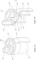
- Figures 4a and 4b are perspective views of exterior and cross-section of a heater assembly 120 connected to a seal joint 410.
- Said seal joint 410 forms part of the air flow passage 140, extending from an air inlet end 440 towards a cartridge end 420.
- the cartridge end 420 is configured to cooperate sealingly with a corresponding connection at the housing 105 so to complete the air flow passage 140.
- the connection between the seal joint 410 to the heater assembly 120 as shown in Figure 4a and 4b , as well as the connection between said seal joint 140 and the housing 105, are both effected by an interference fit in order to provide sealed connections.
- the removable seal also prevents dirt and dust from collecting in the air flow passage 140 and the heater element.
- the tab portion 330 also prevents accidental connection of the cartridge onto the control body 200 prior to its removal because the tab potion 330 would otherwise be in the way of connection. More specifically, the tab portion 330 prevents the heater element being energised before the removable seal is removed.
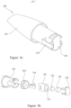
- Figure 5b illustrates an exploded view of the exemplary cartridge of Figure 3 .
- the first portion of the storage compartment is manufactured integrally with the cartridge housing 105 by an injection moulding process.
- the heater assembly 120 is first produced by moulding the heater element with the heater assembly 120, which forms integrally with the second portion of the storage compartment 135.
- the heater assembly 120 comprises electrical contact pads for providing electrical connection to the control circuitry 220.
- a retention material 139 and capillary material 136 are then inserted into the second portion 135 of the storage compartment before said second portion 135 is closed off by an end cap 138.
- the retention material 139 is a fibrous material provided to contain any incoming liquid substrate from the first portion 130, before it is drawn towards the capillary material and be consumed at the heater element.
- the end cap 138 attaches sealingly onto the second portion 135 by an interference fit to keep the capillary material contained in the second portion, as well as prevent leakage and evaporation of liquid substrate from the second portion 135 of the storage compartment.
- the removable seal is then positioned over the heater element to seal it in place.
- a mechanical sealing means 340 is used in this exemplary embodiment, the seal portion 320 of the removable seal 310 may be secured onto the heater element by other cap sealing mechanisms such as induction sealing or glued sealing.
- the seal joint 410 may then installed onto the heater assembly 120 by interference fit, to form the example as shown in Figure 4a and 4b .
- the use of a seal joint 410 is particularly beneficial because the heater element is fully exposed during the application of cap seal, thus providing sufficient free space for an induction sealer or a heat sealer to operate on the cap seal.
- the cartridge and liquid storage compartment may have a different cross-sectional shape and the heater assembly may have a different shape and configuration.
Landscapes
- Chemical & Material Sciences (AREA)
- Chemical Kinetics & Catalysis (AREA)
- General Chemical & Material Sciences (AREA)
- Containers And Packaging Bodies Having A Special Means To Remove Contents (AREA)
- Nozzles (AREA)
- Catching Or Destruction (AREA)
Priority Applications (1)
| Application Number | Priority Date | Filing Date | Title |
|---|---|---|---|
| EP24179275.3A EP4420543A3 (en) | 2017-09-18 | 2018-08-08 | A cartridge for an aerosol-generating system |
Applications Claiming Priority (3)
| Application Number | Priority Date | Filing Date | Title |
|---|---|---|---|
| EP17191636 | 2017-09-18 | ||
| EP18752151.3A EP3684203B1 (en) | 2017-09-18 | 2018-08-08 | A cartridge for an aerosol-generating system |
| PCT/EP2018/071551 WO2019052748A1 (en) | 2017-09-18 | 2018-08-08 | CARTRIDGE FOR AEROSOL GENERATION SYSTEM |
Related Parent Applications (2)
| Application Number | Title | Priority Date | Filing Date |
|---|---|---|---|
| EP18752151.3A Division-Into EP3684203B1 (en) | 2017-09-18 | 2018-08-08 | A cartridge for an aerosol-generating system |
| EP18752151.3A Division EP3684203B1 (en) | 2017-09-18 | 2018-08-08 | A cartridge for an aerosol-generating system |
Related Child Applications (2)
| Application Number | Title | Priority Date | Filing Date |
|---|---|---|---|
| EP24179275.3A Division EP4420543A3 (en) | 2017-09-18 | 2018-08-08 | A cartridge for an aerosol-generating system |
| EP24179275.3A Division-Into EP4420543A3 (en) | 2017-09-18 | 2018-08-08 | A cartridge for an aerosol-generating system |
Publications (3)
| Publication Number | Publication Date |
|---|---|
| EP4176741A1 EP4176741A1 (en) | 2023-05-10 |
| EP4176741B1 true EP4176741B1 (en) | 2024-07-10 |
| EP4176741C0 EP4176741C0 (en) | 2024-07-10 |
Family
ID=59895241
Family Applications (3)
| Application Number | Title | Priority Date | Filing Date |
|---|---|---|---|
| EP22215573.1A Active EP4176741B1 (en) | 2017-09-18 | 2018-08-08 | A cartridge for an aerosol-generating system |
| EP24179275.3A Pending EP4420543A3 (en) | 2017-09-18 | 2018-08-08 | A cartridge for an aerosol-generating system |
| EP18752151.3A Active EP3684203B1 (en) | 2017-09-18 | 2018-08-08 | A cartridge for an aerosol-generating system |
Family Applications After (2)
| Application Number | Title | Priority Date | Filing Date |
|---|---|---|---|
| EP24179275.3A Pending EP4420543A3 (en) | 2017-09-18 | 2018-08-08 | A cartridge for an aerosol-generating system |
| EP18752151.3A Active EP3684203B1 (en) | 2017-09-18 | 2018-08-08 | A cartridge for an aerosol-generating system |
Country Status (13)
| Country | Link |
|---|---|
| US (2) | US12295415B2 (pl) |
| EP (3) | EP4176741B1 (pl) |
| JP (4) | JP7254779B2 (pl) |
| KR (2) | KR102618375B1 (pl) |
| CN (2) | CN116982739A (pl) |
| BR (1) | BR112020003506B1 (pl) |
| IL (2) | IL272286B2 (pl) |
| MX (2) | MX2020002695A (pl) |
| MY (1) | MY205447A (pl) |
| PH (1) | PH12020500083A1 (pl) |
| PL (2) | PL4176741T3 (pl) |
| UA (1) | UA127587C2 (pl) |
| WO (1) | WO2019052748A1 (pl) |
Families Citing this family (27)
| Publication number | Priority date | Publication date | Assignee | Title |
|---|---|---|---|---|
| WO2018086999A1 (en) * | 2016-11-14 | 2018-05-17 | Philip Morris Products S.A. | Aerosol-generating system having variable airflow |
| UA126674C2 (uk) | 2017-02-24 | 2023-01-11 | Філіп Морріс Продактс С.А. | Виконаний литтям під тиском тримач для елемента, що генерує аерозоль, в системі, що генерує аерозоль |
| CA3047676A1 (en) | 2017-02-24 | 2018-08-30 | Philip Morris Products S.A. | An aerosol-generating system and a cartridge for an aerosol-generating system having a two-part liquid storage compartment |
| UA127587C2 (uk) | 2017-09-18 | 2023-10-25 | Філіп Морріс Продактс С.А. | Картридж для генеруючої аерозоль системи |
| DE102017123868B4 (de) | 2017-10-13 | 2019-05-09 | Hauni Maschinenbau Gmbh | Verdampfereinheit für einen Inhalator, insbesondere für ein elektronisches Zigarettenprodukt |
| US11259370B2 (en) | 2017-12-08 | 2022-02-22 | Altria Client Services Llc | Multi-component aerosol-generating device with impact absorbing part |
| GB201720849D0 (en) * | 2017-12-14 | 2018-01-31 | Nicoventures Holdings Ltd | Vapour provision systems |
| CN111936000B (zh) * | 2018-04-26 | 2024-05-28 | 菲利普莫里斯生产公司 | 具有与液体供应隔离的加热器元件的加热器组件 |
| DE102019103987A1 (de) * | 2019-02-18 | 2020-08-20 | Hauni Maschinenbau Gmbh | Verdampfervorrichtung für einen Inhalator, Verbrauchseinheit, Inhalator und Herstellungsverfahren |
| KR102397449B1 (ko) * | 2019-07-23 | 2022-05-12 | 주식회사 케이티앤지 | 에어로졸 생성 장치 |
| WO2021044220A1 (en) * | 2019-09-04 | 2021-03-11 | Sucipto Kokadir | Cartridge with separable components for the evaporation and inhalation of a liquid medium |
| GB201913479D0 (en) * | 2019-09-18 | 2019-10-30 | Nicoventures Trading Ltd | A consumable artcile for use with an apparatus for heating aerosolisable material |
| WO2021123234A1 (en) * | 2019-12-19 | 2021-06-24 | Jt International Sa | Aerosol generation device |
| IL293919B2 (en) | 2019-12-19 | 2025-08-01 | Philip Morris Products Sa | A cartridge for an aerosol-generating system, an aerosol-generating system including a cartridge, and a method of manufacturing a heater assembly and cartridge for an aerosol-generating system |
| EP3864981A1 (en) | 2020-02-13 | 2021-08-18 | Nerudia Limited | Smoking substitute component |
| EP4110106A1 (en) * | 2020-02-28 | 2023-01-04 | JT International SA | Airflow chimney |
| CN115605100A (zh) * | 2020-05-15 | 2023-01-13 | 菲利普莫里斯生产公司(Ch) | 具有多隔室液体贮存器的气溶胶生成制品 |
| US20230210188A1 (en) * | 2020-05-15 | 2023-07-06 | Philip Morris Products S.A. | Aerosol-generating article comprising a liquid reservoir and a transferrable sealing member |
| WO2022034053A1 (en) * | 2020-08-14 | 2022-02-17 | Jt International Sa | Capsule with an airflow path for an electronic cigarette |
| JP7627774B2 (ja) * | 2021-02-18 | 2025-02-06 | フィリップ・モーリス・プロダクツ・ソシエテ・アノニム | 区画壁を有するエアロゾル発生装置 |
| CN115299655A (zh) * | 2021-05-07 | 2022-11-08 | 深圳市合元科技有限公司 | 雾化器及电子雾化装置 |
| KR102637144B1 (ko) * | 2021-06-23 | 2024-02-16 | 주식회사 케이티앤지 | 에어로졸 생성 장치 및 그의 동작 방법 |
| KR102708760B1 (ko) * | 2021-06-23 | 2024-09-24 | 주식회사 케이티앤지 | 에어로졸 생성 장치 및 그의 동작 방법 |
| CN113729308A (zh) * | 2021-10-15 | 2021-12-03 | 北京温致科技有限公司 | 吸嘴组件、加热器和气溶胶生成装置 |
| KR102615473B1 (ko) * | 2021-10-28 | 2023-12-19 | 주식회사 케이티앤지 | 가향 카트리지를 포함하는 에어로졸 발생 장치 |
| CN216651318U (zh) * | 2021-11-22 | 2022-06-03 | 深圳市华诚达精密工业有限公司 | 加热雾化装置及其电子雾化器 |
| CN115299640A (zh) * | 2022-01-25 | 2022-11-08 | 深圳市合元科技有限公司 | 气溶胶生成装置 |
Family Cites Families (94)
| Publication number | Priority date | Publication date | Assignee | Title |
|---|---|---|---|---|
| US5167242A (en) | 1990-06-08 | 1992-12-01 | Kabi Pharmacia Aktiebolaq | Nicotine-impermeable container and method of fabricating the same |
| SE9900215D0 (sv) | 1999-01-26 | 1999-01-26 | Pharmacia & Upjohn Ab | New use |
| US8991402B2 (en) | 2007-12-18 | 2015-03-31 | Pax Labs, Inc. | Aerosol devices and methods for inhaling a substance and uses thereof |
| AT507187B1 (de) | 2008-10-23 | 2010-03-15 | Helmut Dr Buchberger | Inhalator |
| EP2340729A1 (en) | 2009-12-30 | 2011-07-06 | Philip Morris Products S.A. | An improved heater for an electrically heated aerosol generating system |
| AT508244B1 (de) * | 2010-03-10 | 2010-12-15 | Helmut Dr Buchberger | Inhalatorkomponente |
| CA2797975C (en) | 2010-04-30 | 2017-06-06 | Blec, Llc | Electronic smoking device |
| EP2460424A1 (en) | 2010-12-03 | 2012-06-06 | Philip Morris Products S.A. | An aerosol generating system with leakage prevention |
| AU2012214085B2 (en) | 2011-02-11 | 2015-07-09 | Nicoventures Trading Limited | Inhaler component |
| US8528569B1 (en) | 2011-06-28 | 2013-09-10 | Kyle D. Newton | Electronic cigarette with liquid reservoir |
| UA67598U (en) | 2011-08-26 | 2012-02-27 | Дмитрий Юрьевич Рогов | Electronic cigarette |
| US9351522B2 (en) | 2011-09-29 | 2016-05-31 | Robert Safari | Cartomizer e-cigarette |
| RU2489948C2 (ru) | 2011-11-17 | 2013-08-20 | Общество с ограниченной ответственностью "Научно-производственное объединение ЗДОРОВЬЕ" ("НПО ЗДОРОВЬЕ") | Дымообразующая композиция для электронных устройств, имитирующих табакокурение, способ ее получения и применения |
| US9326547B2 (en) | 2012-01-31 | 2016-05-03 | Altria Client Services Llc | Electronic vaping article |
| EP2836090B1 (en) | 2012-04-12 | 2019-03-06 | JT International SA | Aerosol-generating devices |
| KR101690401B1 (ko) | 2012-04-26 | 2017-01-09 | 폰템 홀딩스 1 비.브이. | 밀봉된 카트리지를 갖는 전자 담배 |
| CN104023571B (zh) * | 2012-06-05 | 2017-02-08 | 惠州市吉瑞科技有限公司 | 电子烟及其吸杆 |
| WO2013184951A2 (en) * | 2012-06-06 | 2013-12-12 | Aerodesigns, Inc. | Aerosol dispenser with replaceable cartridge |
| US10004259B2 (en) | 2012-06-28 | 2018-06-26 | Rai Strategic Holdings, Inc. | Reservoir and heater system for controllable delivery of multiple aerosolizable materials in an electronic smoking article |
| US9674894B2 (en) | 2012-12-28 | 2017-06-06 | Philip Morris Products S.A. | Heating assembly for an aerosol generating system |
| WO2014110119A1 (en) | 2013-01-08 | 2014-07-17 | L. Perrigo Company | Electronic cigarette |
| CN203314099U (zh) | 2013-04-03 | 2013-12-04 | 刘秋明 | 一种电子烟 |
| CN203341008U (zh) | 2013-06-06 | 2013-12-18 | 深圳市康尔科技有限公司 | 防漏雾化器 |
| CN203341007U (zh) | 2013-06-06 | 2013-12-18 | 深圳市康尔科技有限公司 | 按压式雾化器 |
| UA116828C2 (uk) | 2013-07-15 | 2018-05-10 | Ніковенчерз Холдінгс Лімітед | Електронний пристрій для одержання пари |
| CN103462224B (zh) | 2013-08-31 | 2015-10-14 | 卓尔悦(常州)电子科技有限公司 | 电子烟雾化器 |
| CN103932401B (zh) | 2013-09-29 | 2015-09-30 | 深圳麦克韦尔股份有限公司 | 电子烟 |
| JP6707447B2 (ja) * | 2013-12-05 | 2020-06-10 | フィリップ・モーリス・プロダクツ・ソシエテ・アノニム | 低抵抗気流経路を備えたエアロゾル発生物品 |
| PL3513673T3 (pl) | 2013-12-23 | 2024-07-08 | Juul Labs International Inc. | Sposoby, układy i urządzenie do odparowywania |
| US10076139B2 (en) | 2013-12-23 | 2018-09-18 | Juul Labs, Inc. | Vaporizer apparatus |
| US9861132B2 (en) | 2013-12-31 | 2018-01-09 | Shenzhen First Union Technology Co., Ltd. | Atomizer and electronic cigarette having same |
| GB201401524D0 (en) | 2014-01-29 | 2014-03-12 | Batmark Ltd | Aerosol-forming member |
| US10015990B2 (en) | 2014-02-10 | 2018-07-10 | Phillip Morris Products S.A. | Aerosol-generating system comprising a device and a cartridge, in which the device ensures electrical contact with the cartridge |
| KR20230167768A (ko) | 2014-02-10 | 2023-12-11 | 필립모리스 프로덕츠 에스.에이. | 히터 조립체를 포함하고 있는 에어로졸 발생 시스템용 카트리지 |
| KR20240032162A (ko) | 2014-02-10 | 2024-03-08 | 필립모리스 프로덕츠 에스.에이. | 히터 조립체를 구비한 에어로졸 발생 시스템용 및 유체 투과성 히터를 구비한 에어로졸 발생 시스템용 카트리지 |
| WO2015117701A1 (en) | 2014-02-10 | 2015-08-13 | Philip Morris Products S.A. | Fluid permeable heater assembly for an aerosol-generating system and method for assembling a fluid permeable heater for an aerosol-generating system |
| WO2015117705A2 (en) | 2014-02-10 | 2015-08-13 | Philip Morris Products S.A. | Cartridge for an aerosol-generating system |
| KR102650793B1 (ko) | 2014-02-10 | 2024-03-26 | 필립모리스 프로덕츠 에스.에이. | 유체 투과성 히터 조립체를 구비한 에어로졸 발생 시스템 |
| GB201413036D0 (en) * | 2014-02-28 | 2014-09-03 | Beyond Twenty Ltd | Beyond 9 |
| WO2015143662A1 (zh) | 2014-03-27 | 2015-10-01 | 深圳麦克韦尔股份有限公司 | 电子烟 |
| SG11201606430QA (en) | 2014-04-30 | 2016-09-29 | Philip Morris Products Sa | A container having a heater for an aerosol-generating device, and aerosol-generating device |
| TWI660685B (zh) * | 2014-05-21 | 2019-06-01 | 瑞士商菲利浦莫里斯製品股份有限公司 | 電熱式氣溶膠產生系統及用於此系統中之匣筒 |
| TWI661782B (zh) | 2014-05-21 | 2019-06-11 | Philip Morris Products S. A. | 電熱式氣溶膠產生系統、電熱式氣溶膠產生裝置及產生氣溶膠之方法 |
| US9955726B2 (en) | 2014-05-23 | 2018-05-01 | Rai Strategic Holdings, Inc. | Sealed cartridge for an aerosol delivery device and related assembly method |
| GB201410562D0 (en) | 2014-06-13 | 2014-07-30 | Nicoventures Holdings Ltd | Aerosol provision system |
| GB2527597B (en) * | 2014-06-27 | 2016-11-23 | Relco Induction Dev Ltd | Electronic Vapour Inhalers |
| CN203969207U (zh) * | 2014-07-08 | 2014-12-03 | 深圳市康尔科技有限公司 | 顶部注液底部换发热组件的电子烟 |
| WO2016004576A1 (zh) * | 2014-07-08 | 2016-01-14 | 深圳市康尔科技有限公司 | 顶部注液底部换发热组件的电子烟 |
| JP6697437B2 (ja) | 2014-07-11 | 2020-05-20 | フィリップ・モーリス・プロダクツ・ソシエテ・アノニム | 保護箔を備えるエアロゾル形成カートリッジ |
| JP6734838B2 (ja) | 2014-07-11 | 2020-08-05 | フィリップ・モーリス・プロダクツ・ソシエテ・アノニム | たばこ含有材料を含むエアロゾル形成カートリッジ |
| RU2685285C2 (ru) | 2014-07-11 | 2019-04-17 | Филип Моррис Продактс С.А. | Картридж, образующий аэрозоль, который содержит источник жидкого никотина |
| US9675118B2 (en) | 2014-08-29 | 2017-06-13 | Shenzhen Smoore Technology Limited | Electronic cigarette and atomizer assembly mounting base thereof |
| EP3760059B1 (en) | 2014-09-17 | 2022-10-26 | Fontem Holdings 4 B.V. | Device for storing and vaporizing liquid media |
| US20170295846A1 (en) | 2014-09-19 | 2017-10-19 | Huizhou Kimree Technology Co., Ltd. | Vaporization assembly and electronic cigarette |
| DE102014114133A1 (de) | 2014-09-29 | 2016-03-31 | Aie Investments S.A. | Elektrische Zigarette |
| JP6748075B2 (ja) | 2014-10-20 | 2020-08-26 | ニューメリカル・デザイン・インコーポレイテッド | 液体の気化のためのマイクロ流体を基礎とする装置及び方法 |
| KR101924744B1 (ko) | 2014-11-10 | 2018-12-03 | 니뽄 다바코 산교 가부시키가이샤 | 비연소형 향미 흡인기 |
| EP3220759A1 (en) * | 2014-11-17 | 2017-09-27 | McNeil AB | Disposable cartridge for use in an electronic nicotine delivery system |
| GB2533135B (en) | 2014-12-11 | 2020-11-11 | Nicoventures Holdings Ltd | Aerosol provision systems |
| TWI674071B (zh) | 2014-12-15 | 2019-10-11 | 瑞士商菲利浦莫里斯製品股份有限公司 | 氣溶膠產生系統及用於在電熱式氣溶膠產生系統內導引氣流的方法 |
| JP6689855B2 (ja) | 2014-12-15 | 2020-04-28 | フィリップ・モーリス・プロダクツ・ソシエテ・アノニム | 移動可能なカートリッジを備えたエアロゾル発生システム |
| CA2970045A1 (en) | 2014-12-15 | 2016-06-23 | Philip Morris Products S.A. | An aerosol-generating system using the venturi effect to deliver substrate to a heating element |
| CN107105770B (zh) | 2014-12-23 | 2019-12-13 | 惠州市吉瑞科技有限公司 | 电子烟 |
| CN104738816B (zh) | 2015-02-04 | 2024-08-02 | 深圳市合元科技有限公司 | 雾化器和电子烟以及适于更换的储液器件 |
| US10172388B2 (en) | 2015-03-10 | 2019-01-08 | Rai Strategic Holdings, Inc. | Aerosol delivery device with microfluidic delivery component |
| WO2016145612A1 (zh) | 2015-03-17 | 2016-09-22 | 惠州市吉瑞科技有限公司 | 一种雾化组件及电子烟 |
| EP2921065A1 (en) | 2015-03-31 | 2015-09-23 | Philip Morris Products S.a.s. | Extended heating and heating assembly for an aerosol generating system |
| EP3075271B2 (en) * | 2015-04-02 | 2022-09-14 | Fontem Holdings 1 B.V. | Electronic smoking device with liquid reservoir including an actuator |
| CN204617067U (zh) | 2015-04-17 | 2015-09-09 | 刘翔 | 带多种雾化器的电子烟套件 |
| EP3406285B1 (en) | 2015-04-22 | 2021-06-02 | Altria Client Services LLC | Pod assembly, dispensing body, and e-vapor apparatus including the same |
| UA125169C2 (uk) | 2015-04-23 | 2022-01-26 | Олтріа Клайєнт Сервісиз Ллк | Єдиний нагрівальний елемент і нагрівач, картридж і електронний випаровувальний пристрій з єдиним нагрівальним елементом |
| JP6924156B2 (ja) | 2015-06-12 | 2021-08-25 | フィリップ・モーリス・プロダクツ・ソシエテ・アノニム | エアロゾル発生システムのためのカートリッジ |
| US10206429B2 (en) | 2015-07-24 | 2019-02-19 | Rai Strategic Holdings, Inc. | Aerosol delivery device with radiant heating |
| KR102661604B1 (ko) * | 2015-09-11 | 2024-04-29 | 필립모리스 프로덕츠 에스.에이. | 카트리지 및 카트리지를 포함하는 에어로졸 형성 물품용 시스템 |
| GB2542838B (en) * | 2015-10-01 | 2022-01-12 | Nicoventures Trading Ltd | Aerosol provision system |
| EP3155907B1 (en) * | 2015-10-15 | 2018-06-06 | Fontem Holdings 1 B.V. | Electronic cigarette with multicameral liquid reservoir |
| CN205337599U (zh) | 2015-10-22 | 2016-06-29 | 深圳麦克韦尔股份有限公司 | 电子烟及其雾化组件和雾化元件 |
| CN205512340U (zh) | 2016-01-11 | 2016-08-31 | 常州聚为智能科技有限公司 | 雾化头及其电子烟 |
| GB201602831D0 (en) | 2016-02-18 | 2016-04-06 | British American Tobacco Co | Flavour delivery device |
| DE202016100917U1 (de) | 2016-02-22 | 2016-03-09 | Türk & Hillinger GmbH | Luft- und/oder Aerosolerhitzer |
| WO2017153827A1 (en) * | 2016-03-07 | 2017-09-14 | Wallbrooke Investments Ltd. | Inductive heating apparatus and related method |
| DE102016002665A1 (de) * | 2016-03-08 | 2017-09-14 | Hauni Maschinenbau Gmbh | Elektronisches Zigarettenprodukt und Kartusche für ein elektronisches Zigarettenprodukt |
| US10231486B2 (en) * | 2016-03-10 | 2019-03-19 | Pax Labs, Inc. | Vaporization device having integrated games |
| CN105559151B (zh) | 2016-03-21 | 2019-05-24 | 湖南中烟工业有限责任公司 | 一种超声波雾化器及电子烟 |
| US10952471B2 (en) | 2016-05-31 | 2021-03-23 | Altria Client Services Llc | Aerosol-generating device with integral heater assembly |
| CN105876873B (zh) | 2016-06-30 | 2018-12-07 | 湖南中烟工业有限责任公司 | 一种组合式超声雾化器及其雾化方法、电子烟 |
| US10080387B2 (en) | 2016-09-23 | 2018-09-25 | Rai Strategic Holdings, Inc. | Aerosol delivery device with replaceable wick and heater assembly |
| CN206197017U (zh) * | 2016-10-12 | 2017-05-31 | 深圳市艾维普思科技股份有限公司 | 电子烟 |
| CN206423562U (zh) * | 2016-11-28 | 2017-08-22 | 深圳市艾维普思科技股份有限公司 | 电子烟及其双层储油结构 |
| CN206603236U (zh) | 2017-01-10 | 2017-11-03 | 深圳市艾维普思科技股份有限公司 | 电子烟 |
| EP3569075A4 (en) | 2017-02-08 | 2020-09-02 | Japan Tobacco, Inc. | CARTRIDGE AND INHALER |
| UA126674C2 (uk) | 2017-02-24 | 2023-01-11 | Філіп Морріс Продактс С.А. | Виконаний литтям під тиском тримач для елемента, що генерує аерозоль, в системі, що генерує аерозоль |
| CA3047676A1 (en) | 2017-02-24 | 2018-08-30 | Philip Morris Products S.A. | An aerosol-generating system and a cartridge for an aerosol-generating system having a two-part liquid storage compartment |
| UA127587C2 (uk) | 2017-09-18 | 2023-10-25 | Філіп Морріс Продактс С.А. | Картридж для генеруючої аерозоль системи |
-
2018
- 2018-08-08 UA UAA202001404A patent/UA127587C2/uk unknown
- 2018-08-08 BR BR112020003506-8A patent/BR112020003506B1/pt active IP Right Grant
- 2018-08-08 IL IL272286A patent/IL272286B2/en unknown
- 2018-08-08 KR KR1020207006952A patent/KR102618375B1/ko active Active
- 2018-08-08 WO PCT/EP2018/071551 patent/WO2019052748A1/en not_active Ceased
- 2018-08-08 PL PL22215573.1T patent/PL4176741T3/pl unknown
- 2018-08-08 EP EP22215573.1A patent/EP4176741B1/en active Active
- 2018-08-08 CN CN202310969479.9A patent/CN116982739A/zh active Pending
- 2018-08-08 MX MX2020002695A patent/MX2020002695A/es unknown
- 2018-08-08 EP EP24179275.3A patent/EP4420543A3/en active Pending
- 2018-08-08 JP JP2020515922A patent/JP7254779B2/ja active Active
- 2018-08-08 IL IL302436A patent/IL302436B2/en unknown
- 2018-08-08 EP EP18752151.3A patent/EP3684203B1/en active Active
- 2018-08-08 MY MYPI2020000389A patent/MY205447A/en unknown
- 2018-08-08 KR KR1020237043818A patent/KR20240005117A/ko active Pending
- 2018-08-08 CN CN201880055055.9A patent/CN111031824B/zh active Active
- 2018-08-08 PL PL18752151.3T patent/PL3684203T3/pl unknown
- 2018-11-08 US US16/184,322 patent/US12295415B2/en active Active
-
2020
- 2020-01-10 PH PH12020500083A patent/PH12020500083A1/en unknown
- 2020-03-10 MX MX2024004908A patent/MX2024004908A/es unknown
-
2023
- 2023-01-10 JP JP2023001599A patent/JP7454715B2/ja active Active
-
2024
- 2024-03-11 JP JP2024037000A patent/JP7784462B2/ja active Active
-
2025
- 2025-03-21 US US19/086,459 patent/US20250212955A1/en active Pending
- 2025-12-01 JP JP2025210078A patent/JP2026020390A/ja active Pending
Also Published As
Similar Documents
| Publication | Publication Date | Title |
|---|---|---|
| US20250212955A1 (en) | Cartridge with first compartment in fluid communication with second compartment | |
| EP3585190B1 (en) | Moulded mounting for an aerosol-generating element in an aerosol-generating system | |
| AU2018224736B2 (en) | An aerosol-generating system and a cartridge for an aerosol generating system having a two-part liquid storage compartment | |
| HK40092269A (en) | A cartridge for an aerosol-generating system | |
| HK40092269B (en) | A cartridge for an aerosol-generating system | |
| HK40111801A (en) | A cartridge for an aerosol-generating system | |
| RU2781999C2 (ru) | Генерирующая аэрозоль система (варианты) и картридж для генерирующей аэрозоль системы | |
| HK40027659B (en) | A cartridge for an aerosol-generating system | |
| HK40027659A (en) | A cartridge for an aerosol-generating system | |
| RU2779428C2 (ru) | Картридж для генерирующей аэрозоль системы | |
| HK40016012B (en) | Moulded mounting for an aerosol-generating element in an aerosol-generating system | |
| HK40016012A (en) | Moulded mounting for an aerosol-generating element in an aerosol-generating system | |
| HK40015461B (en) | An aerosol-generating system and a cartridge for an aerosol generating system having a two-part liquid storage compartment | |
| HK40015461A (en) | An aerosol-generating system and a cartridge for an aerosol generating system having a two-part liquid storage compartment |
Legal Events
| Date | Code | Title | Description |
|---|---|---|---|
| PUAI | Public reference made under article 153(3) epc to a published international application that has entered the european phase |
Free format text: ORIGINAL CODE: 0009012 |
|
| STAA | Information on the status of an ep patent application or granted ep patent |
Free format text: STATUS: THE APPLICATION HAS BEEN PUBLISHED |
|
| AC | Divisional application: reference to earlier application |
Ref document number: 3684203 Country of ref document: EP Kind code of ref document: P |
|
| AK | Designated contracting states |
Kind code of ref document: A1 Designated state(s): AL AT BE BG CH CY CZ DE DK EE ES FI FR GB GR HR HU IE IS IT LI LT LU LV MC MK MT NL NO PL PT RO RS SE SI SK SM TR |
|
| STAA | Information on the status of an ep patent application or granted ep patent |
Free format text: STATUS: REQUEST FOR EXAMINATION WAS MADE |
|
| 17P | Request for examination filed |
Effective date: 20230719 |
|
| RBV | Designated contracting states (corrected) |
Designated state(s): AL AT BE BG CH CY CZ DE DK EE ES FI FR GB GR HR HU IE IS IT LI LT LU LV MC MK MT NL NO PL PT RO RS SE SI SK SM TR |
|
| REG | Reference to a national code |
Ref country code: HK Ref legal event code: DE Ref document number: 40092269 Country of ref document: HK |
|
| GRAP | Despatch of communication of intention to grant a patent |
Free format text: ORIGINAL CODE: EPIDOSNIGR1 |
|
| STAA | Information on the status of an ep patent application or granted ep patent |
Free format text: STATUS: GRANT OF PATENT IS INTENDED |
|
| RIC1 | Information provided on ipc code assigned before grant |
Ipc: A24F 40/30 20200101ALN20240116BHEP Ipc: A24F 40/10 20200101ALN20240116BHEP Ipc: A24F 40/485 20200101ALI20240116BHEP Ipc: A24F 40/42 20200101AFI20240116BHEP |
|
| INTG | Intention to grant announced |
Effective date: 20240201 |
|
| GRAS | Grant fee paid |
Free format text: ORIGINAL CODE: EPIDOSNIGR3 |
|
| GRAA | (expected) grant |
Free format text: ORIGINAL CODE: 0009210 |
|
| STAA | Information on the status of an ep patent application or granted ep patent |
Free format text: STATUS: THE PATENT HAS BEEN GRANTED |
|
| AC | Divisional application: reference to earlier application |
Ref document number: 3684203 Country of ref document: EP Kind code of ref document: P |
|
| AK | Designated contracting states |
Kind code of ref document: B1 Designated state(s): AL AT BE BG CH CY CZ DE DK EE ES FI FR GB GR HR HU IE IS IT LI LT LU LV MC MK MT NL NO PL PT RO RS SE SI SK SM TR |
|
| REG | Reference to a national code |
Ref country code: CH Ref legal event code: EP |
|
| REG | Reference to a national code |
Ref country code: DE Ref legal event code: R096 Ref document number: 602018071773 Country of ref document: DE |
|
| U01 | Request for unitary effect filed |
Effective date: 20240710 |
|
| U07 | Unitary effect registered |
Designated state(s): AT BE BG DE DK EE FI FR IT LT LU LV MT NL PT SE SI Effective date: 20240716 |
|
| U1N | Appointed representative for the unitary patent procedure changed after the registration of the unitary effect |
Representative=s name: REDDIE & GROSE LLP; GB |
|
| U20 | Renewal fee for the european patent with unitary effect paid |
Year of fee payment: 7 Effective date: 20240925 |
|
| PG25 | Lapsed in a contracting state [announced via postgrant information from national office to epo] |
Ref country code: NO Free format text: LAPSE BECAUSE OF FAILURE TO SUBMIT A TRANSLATION OF THE DESCRIPTION OR TO PAY THE FEE WITHIN THE PRESCRIBED TIME-LIMIT Effective date: 20241010 |
|
| PG25 | Lapsed in a contracting state [announced via postgrant information from national office to epo] |
Ref country code: GR Free format text: LAPSE BECAUSE OF FAILURE TO SUBMIT A TRANSLATION OF THE DESCRIPTION OR TO PAY THE FEE WITHIN THE PRESCRIBED TIME-LIMIT Effective date: 20241011 |
|
| PG25 | Lapsed in a contracting state [announced via postgrant information from national office to epo] |
Ref country code: IS Free format text: LAPSE BECAUSE OF FAILURE TO SUBMIT A TRANSLATION OF THE DESCRIPTION OR TO PAY THE FEE WITHIN THE PRESCRIBED TIME-LIMIT Effective date: 20241110 |
|
| PG25 | Lapsed in a contracting state [announced via postgrant information from national office to epo] |
Ref country code: HR Free format text: LAPSE BECAUSE OF FAILURE TO SUBMIT A TRANSLATION OF THE DESCRIPTION OR TO PAY THE FEE WITHIN THE PRESCRIBED TIME-LIMIT Effective date: 20240710 |
|
| PG25 | Lapsed in a contracting state [announced via postgrant information from national office to epo] |
Ref country code: ES Free format text: LAPSE BECAUSE OF FAILURE TO SUBMIT A TRANSLATION OF THE DESCRIPTION OR TO PAY THE FEE WITHIN THE PRESCRIBED TIME-LIMIT Effective date: 20240710 Ref country code: RS Free format text: LAPSE BECAUSE OF FAILURE TO SUBMIT A TRANSLATION OF THE DESCRIPTION OR TO PAY THE FEE WITHIN THE PRESCRIBED TIME-LIMIT Effective date: 20241010 |
|
| PG25 | Lapsed in a contracting state [announced via postgrant information from national office to epo] |
Ref country code: RS Free format text: LAPSE BECAUSE OF FAILURE TO SUBMIT A TRANSLATION OF THE DESCRIPTION OR TO PAY THE FEE WITHIN THE PRESCRIBED TIME-LIMIT Effective date: 20241010 Ref country code: NO Free format text: LAPSE BECAUSE OF FAILURE TO SUBMIT A TRANSLATION OF THE DESCRIPTION OR TO PAY THE FEE WITHIN THE PRESCRIBED TIME-LIMIT Effective date: 20241010 Ref country code: IS Free format text: LAPSE BECAUSE OF FAILURE TO SUBMIT A TRANSLATION OF THE DESCRIPTION OR TO PAY THE FEE WITHIN THE PRESCRIBED TIME-LIMIT Effective date: 20241110 Ref country code: HR Free format text: LAPSE BECAUSE OF FAILURE TO SUBMIT A TRANSLATION OF THE DESCRIPTION OR TO PAY THE FEE WITHIN THE PRESCRIBED TIME-LIMIT Effective date: 20240710 Ref country code: GR Free format text: LAPSE BECAUSE OF FAILURE TO SUBMIT A TRANSLATION OF THE DESCRIPTION OR TO PAY THE FEE WITHIN THE PRESCRIBED TIME-LIMIT Effective date: 20241011 Ref country code: ES Free format text: LAPSE BECAUSE OF FAILURE TO SUBMIT A TRANSLATION OF THE DESCRIPTION OR TO PAY THE FEE WITHIN THE PRESCRIBED TIME-LIMIT Effective date: 20240710 |
|
| PG25 | Lapsed in a contracting state [announced via postgrant information from national office to epo] |
Ref country code: SM Free format text: LAPSE BECAUSE OF FAILURE TO SUBMIT A TRANSLATION OF THE DESCRIPTION OR TO PAY THE FEE WITHIN THE PRESCRIBED TIME-LIMIT Effective date: 20240710 |
|
| PG25 | Lapsed in a contracting state [announced via postgrant information from national office to epo] |
Ref country code: MC Free format text: LAPSE BECAUSE OF FAILURE TO SUBMIT A TRANSLATION OF THE DESCRIPTION OR TO PAY THE FEE WITHIN THE PRESCRIBED TIME-LIMIT Effective date: 20240710 |
|
| PG25 | Lapsed in a contracting state [announced via postgrant information from national office to epo] |
Ref country code: CZ Free format text: LAPSE BECAUSE OF FAILURE TO SUBMIT A TRANSLATION OF THE DESCRIPTION OR TO PAY THE FEE WITHIN THE PRESCRIBED TIME-LIMIT Effective date: 20240710 |
|
| PG25 | Lapsed in a contracting state [announced via postgrant information from national office to epo] |
Ref country code: SK Free format text: LAPSE BECAUSE OF FAILURE TO SUBMIT A TRANSLATION OF THE DESCRIPTION OR TO PAY THE FEE WITHIN THE PRESCRIBED TIME-LIMIT Effective date: 20240710 |
|
| PLBE | No opposition filed within time limit |
Free format text: ORIGINAL CODE: 0009261 |
|
| STAA | Information on the status of an ep patent application or granted ep patent |
Free format text: STATUS: NO OPPOSITION FILED WITHIN TIME LIMIT |
|
| 26N | No opposition filed |
Effective date: 20250411 |
|
| PG25 | Lapsed in a contracting state [announced via postgrant information from national office to epo] |
Ref country code: IE Free format text: LAPSE BECAUSE OF NON-PAYMENT OF DUE FEES Effective date: 20240808 |
|
| U20 | Renewal fee for the european patent with unitary effect paid |
Year of fee payment: 8 Effective date: 20250827 |
|
| PGFP | Annual fee paid to national office [announced via postgrant information from national office to epo] |
Ref country code: PL Payment date: 20250806 Year of fee payment: 8 |
|
| PGFP | Annual fee paid to national office [announced via postgrant information from national office to epo] |
Ref country code: GB Payment date: 20250820 Year of fee payment: 8 |
|
| PGFP | Annual fee paid to national office [announced via postgrant information from national office to epo] |
Ref country code: CH Payment date: 20250901 Year of fee payment: 8 |
|
| PGFP | Annual fee paid to national office [announced via postgrant information from national office to epo] |
Ref country code: RO Payment date: 20250804 Year of fee payment: 8 |
|
| PG25 | Lapsed in a contracting state [announced via postgrant information from national office to epo] |
Ref country code: CY Free format text: LAPSE BECAUSE OF FAILURE TO SUBMIT A TRANSLATION OF THE DESCRIPTION OR TO PAY THE FEE WITHIN THE PRESCRIBED TIME-LIMIT; INVALID AB INITIO Effective date: 20180808 |