EP4172097B1 - Kompakte und tragbare hebeanordnung, umbausatz für eine hebeanordnung und verfahren zur montage solch eines umbausatzes - Google Patents
Kompakte und tragbare hebeanordnung, umbausatz für eine hebeanordnung und verfahren zur montage solch eines umbausatzes Download PDFInfo
- Publication number
- EP4172097B1 EP4172097B1 EP21736997.4A EP21736997A EP4172097B1 EP 4172097 B1 EP4172097 B1 EP 4172097B1 EP 21736997 A EP21736997 A EP 21736997A EP 4172097 B1 EP4172097 B1 EP 4172097B1
- Authority
- EP
- European Patent Office
- Prior art keywords
- lifting
- hoist
- lifting arrangement
- arrangement
- suspension bolt
- Prior art date
- Legal status (The legal status is an assumption and is not a legal conclusion. Google has not performed a legal analysis and makes no representation as to the accuracy of the status listed.)
- Active
Links
Images




Classifications
-
- B—PERFORMING OPERATIONS; TRANSPORTING
- B66—HOISTING; LIFTING; HAULING
- B66C—CRANES; LOAD-ENGAGING ELEMENTS OR DEVICES FOR CRANES, CAPSTANS, WINCHES, OR TACKLES
- B66C11/00—Trolleys or crabs, e.g. operating above runways
- B66C11/02—Trolleys or crabs, e.g. operating above runways with operating gear or operator's cabin suspended, or laterally offset, from runway or track
- B66C11/04—Underhung trolleys
- B66C11/06—Underhung trolleys running on monorails
-
- B—PERFORMING OPERATIONS; TRANSPORTING
- B66—HOISTING; LIFTING; HAULING
- B66C—CRANES; LOAD-ENGAGING ELEMENTS OR DEVICES FOR CRANES, CAPSTANS, WINCHES, OR TACKLES
- B66C1/00—Load-engaging elements or devices attached to lifting or lowering gear of cranes or adapted for connection therewith for transmitting lifting forces to articles or groups of articles
- B66C1/10—Load-engaging elements or devices attached to lifting or lowering gear of cranes or adapted for connection therewith for transmitting lifting forces to articles or groups of articles by mechanical means
- B66C1/108—Load-engaging elements or devices attached to lifting or lowering gear of cranes or adapted for connection therewith for transmitting lifting forces to articles or groups of articles by mechanical means for lifting parts of wind turbines
-
- B—PERFORMING OPERATIONS; TRANSPORTING
- B66—HOISTING; LIFTING; HAULING
- B66C—CRANES; LOAD-ENGAGING ELEMENTS OR DEVICES FOR CRANES, CAPSTANS, WINCHES, OR TACKLES
- B66C11/00—Trolleys or crabs, e.g. operating above runways
- B66C11/16—Rope, cable, or chain drives for trolleys; Combinations of such drives with hoisting gear
-
- B—PERFORMING OPERATIONS; TRANSPORTING
- B66—HOISTING; LIFTING; HAULING
- B66D—CAPSTANS; WINCHES; TACKLES, e.g. PULLEY BLOCKS; HOISTS
- B66D3/00—Portable or mobile lifting or hauling appliances
- B66D3/12—Chain or like hand-operated tackles with or without power transmission gearing between operating member and lifting rope, chain or cable
-
- B—PERFORMING OPERATIONS; TRANSPORTING
- B66—HOISTING; LIFTING; HAULING
- B66D—CAPSTANS; WINCHES; TACKLES, e.g. PULLEY BLOCKS; HOISTS
- B66D3/00—Portable or mobile lifting or hauling appliances
- B66D3/12—Chain or like hand-operated tackles with or without power transmission gearing between operating member and lifting rope, chain or cable
- B66D3/16—Chain or like hand-operated tackles with or without power transmission gearing between operating member and lifting rope, chain or cable operated by an endless chain passing over a pulley or a sprocket
-
- B—PERFORMING OPERATIONS; TRANSPORTING
- B66—HOISTING; LIFTING; HAULING
- B66D—CAPSTANS; WINCHES; TACKLES, e.g. PULLEY BLOCKS; HOISTS
- B66D3/00—Portable or mobile lifting or hauling appliances
- B66D3/18—Power-operated hoists
-
- B—PERFORMING OPERATIONS; TRANSPORTING
- B66—HOISTING; LIFTING; HAULING
- B66D—CAPSTANS; WINCHES; TACKLES, e.g. PULLEY BLOCKS; HOISTS
- B66D3/00—Portable or mobile lifting or hauling appliances
- B66D3/18—Power-operated hoists
- B66D3/26—Other details, e.g. housings
-
- B—PERFORMING OPERATIONS; TRANSPORTING
- B66—HOISTING; LIFTING; HAULING
- B66C—CRANES; LOAD-ENGAGING ELEMENTS OR DEVICES FOR CRANES, CAPSTANS, WINCHES, OR TACKLES
- B66C2700/00—Cranes
- B66C2700/01—General aspects of mobile cranes, overhead travelling cranes, gantry cranes, loading bridges, cranes for building ships on slipways, cranes for foundries or cranes for public works
- B66C2700/012—Trolleys or runways
- B66C2700/014—Devices for trolleys running on monorails
- B66C2700/015—Arrangements which are easily displaceable or dismountable
Definitions
- the present disclosure relates to a lifting arrangement, such as a hoist, and especially to a chain hoist.
- hoists In the field of lifting equipment, there are hoists in many different designs and for different purposes. Hoists are generally arranged to aid heavy lifting in any range from less than 100 kg to several tons. A hoist can be arranged in a ceiling area by a static arrangement, such as a hook, or by a movable arrangement, such as a traverse.
- a traverse can be a simple arrangement including a single beam in one direction, or a more complex unit including a multi-beam arrangement, which then allows for lifting and moving in three dimensions in the room.
- a challenge in the field is, for example during maintenance, to combine a heavy lifting arrangement in a narrow space, where the need of moving the heavy equipment around, and the safety for the operator.
- Examples of such narrow spaces may be for instance in the machine room of a windmill, engine rooms in ships and industrial ventilations units and many other areas where large industrial machinery is used. In such areas, it is a challenge to fit traverse beams which allows the heavy equipment to be lifted and moved around as needed, and where the operators and service personnel have difficulty to physically fit.
- the equipment to be lifted may have a load of 1000 kg.
- a way to solve the above problems is by using hoists with a low headroom.
- a low headroom means that the distance between the bottom of the beam and the lifting point of the load hook is as short as possible. More technically, the headroom may be defined by the Hmin and D2 values wherein the Hmin measurement is the measurement taken from the bottom surface of the beam to the inner surface of the hook of which load is hung and the D2 measurement is measured from the surface of the flange of the beam on which wheels of the trolley are arranged to the lowest point of the lifting arrangement.
- a low headroom potentially allows the lifting arrangement to lift the equipment higher, which is necessary where the space is narrow.
- a way to solve this is to provide a lifting arrangement having an elongated trolley.
- the elongated trolley thus comprises a section where the load may be lifted having the lesser Hmin value and another section where the chain hoist and extra load chain is arranged having the much larger D2 value. In that way the lifting section may be less affected by the large equipment.
- hoists are very big and bulky, and does not solve the problem with the large D2 value. Due to their size, they often weigh more than 70 kilograms.
- a further disadvantage with the above described solutions is that the chain hoists available are expensive since the trollies used on the lifting arrangement are specialized. They typically need a lot of extra load chain since the available products require a large mass of load chain, since the chain is lead through the lifting arrangement in many instances and over many bends. Further, they are heavy and difficult to mount for one person. Thus, at least two persons may be needed, and still it is an awkward and a potentially dangerous operation from an ergonomic and a working environment point of view.
- a lifting operation e.g. when performing maintenance, repair and service in a machine room on a ship or the nacelle of a windmill.
- the ceiling is close to machinery, which means that the vertical distance that is available is narrow.
- the development project originated with a request for a low headroom chain hoist with a headroom minimum of 150 mm or less and be able to lift a load of 1000 kg. Furthermore, a number of additional requirements were desired; a maximum weight of 15 kg for the entire arrangement, and that one person should be able to mount it and take it down alone.
- the arrangement must be able to lift the heavy load in a secure way.
- the arrangement must be light enough for installation by one person, since a traverse beam usually is arranged high in a ceiling, above the head. Furthermore, during the operation of lifting and moving the equipment, the physical strain on the operating personnel must be kept to a minimum.
- the product preferably should be portable and easy for one person to bring along. This is due to several factors. For instance, the maintenance intervals in some industrial sites, such as windmills are generally long, and the lifting arrangements are not used very often, which mean that it is more economic if the arrangement can be portable so that it can be used in many windmills.
- the lifting arrangement according to the invention can be used in any place where the headroom is low and there is a standard beam.
- a further objective is to provide a lifting arrangement which is light, portable, has low headroom and is easy to mount and which enables mounting and release by one person at the time when it is needed.
- a further objective is to provide a conversion kit which may retroactively be installed on a standard trolley.
- a further object is to provide a method for mounting the conversion kit onto a trolley of the lifting arrangement.
- a further object is to provide a method for installation of the lifting arrangement onto a beam.
- the head room which states the possible height the load can be elevated in relation to the beam is set by the Hmin measurement and the D2 measurement of the lifting arrangement.
- the Hmin measurement is the distance between the bottom of the beam and the lifting point of the load hook and the D2 measurement is the distance from the lowest point of the structure to the surface of the flange of the beam that the wheels of the trolley rests on.
- any terms, including relative terms, such as “up”, “down”, “below”, “above”, or the like is in relation to the orientation of the lifting arrangement when in use.
- “Up” or the upper side of the arrangement is in the direction of the ceiling.
- “down”, “lower”, or “bottom” is thus in the direction towards the floor.
- the respective side of the lifting arrangement is defined as located towards a housing or a cover plate. In this particular lifting arrangement, the side is parallel to the extension of the beam.
- the centre plane is the vertical plane that runs in the centre of the lifting arrangement along a centre axis. Typically, the direction of the centre axis is the horizontal extension of the beam. The centre is located in between the two sides. In this lifting arrangement the centre axis is an axis extending from the "front" of the lifting arrangement to the "rear”.
- the centre plane may also be referred to as the symmetry plane.
- “Longitudinally” in relation to the lifting arrangement is defined as the direction of the elongation of the symmetry plane of the lifting arrangement.
- the challenge is thus to decrease the Hmin value, as well as the D2 value as much as possible in order to increase the lifting height, and to decrease the weight of the lifting arrangement itself, so that one person can handle it.
- the problems of the prior art are solved by a detachable hoist conversion kit according to claim 1.
- the lifting arrangement comprises a body and lifting means for vertical lift, such as a chain, rope, wire rope or fibre rope and a load connecting means, such as a hook, for releasably engaging the load to be lifted.
- the lifting means passes through the body between a hoisting location and a lifting location.
- the body comprises a first body side plate and a second body side plate for symmetrical arrangement around a body symmetry plane.
- a suspension bolt is arranged for connecting the first and the second body side plates to each other.
- There is a hoist actuating unit operating the lifting arrangement to perform the lifting and lowering.
- the actuating unit is used for actuating a rotation and thus driving the lifting means in a lifting or lowering direction.
- the inventive hoist conversion kit which is arranged to be detachably arranged to the body and which has a guiding unit which comprises a holder, and an external guide wheel arranged within the holder.
- the external guide wheel is arranged for guiding the lifting means from its lifting location from which lifting location vertical lift is enabled and substantially longitudinally through the body directly to an internal guide wheel included in the hoist actuating unit, and wherein the guiding unit is arranged on the suspension bolt.
- any standard chain hoist with standard chain and standard dimensions may be used as the base.
- a chain hoist which already is small in size may be used.
- the body of the lifting arrangement is held together by a suspension bolt.
- a suspension bolt For a compact arrangement there may be provided one single suspension bolt.
- This suspension bolt is used for arranging the holder with the external guiding wheel. This in turn results in fewer parts and shorter distance between the hoist actuating unit to the low headroom lifting position by using the parts already available in the chain hoist.
- the hoist actuating unit may be a standard unit which may be arranged to the body or in the close vicinity of the body.
- the hoist actuating unit is arranged so that the internal guide wheel is arranged at a horizontal position which is different from a horizontal position of the external guide wheel, as seen in the body symmetry plane.
- the hoist conversion kit may thus be adapted to be arranged so as to meet the requirements of the Hmin and D2 measurements, by arranging the hoist actuating unit and the guiding means at a position horizontally separate in relation to each other. In that way, the risk that the hoist actuating unit, the lifting means and the load connecting means are arranged too close is prevented.
- the lifting means may thus be led through the lifting arrangement longitudinally, between the external guide wheel and the internal guide wheel, from the hoist location to its lifting location. If desired, the lifting means may be led through the lifting arrangement substantially horizontally.
- the guiding unit and the hoist actuating unit be arranged as close as possible, given the physical restrictions of the body, the surroundings, and the suspension bolt.
- the lowest point of the structure of the lifting unit may preferably be higher up than Hmin. If this is not the case, the lowest point of the structure could restrict the product from achieving Hmin when lifting, depending on the size and format of the object being lifted.
- a pair of covers may be arranged to the respective body side plates.
- the body side plates may be prepared for attaching the covers.
- the hoist actuating unit does not need to be hung, since a hanging hoist actuating unit adds to the D2 value.
- the hoist actuating unit may be fixedly arranged in at least one of the covers in order to prevent the hoist actuating unit to rotate, spin, or rattle within the covers. This may be done by fastening means, such as screws or clips.
- the covers may be of a shape that corresponds to the shape of the hoist actuating unit.
- the hoist actuating unit may typically be substantially round in shape. It is possible that the actuating unit may be fixed in the cover by a press fit or interference fit.
- At least one of the covers may be detachably connected to the body.
- the body may be made from aluminium.
- the suspension bolt may be from aluminium.
- the use of a lightweight metal such as aluminium may reduce the weight of the lifting arrangement and still maintain the safety and strength requirements of a chain hoist made by cast iron or steel.
- the total weight of the lifting arrangement may be adapted so that one person can handle the arrangement and install the lifting arrangement at the time when it is needed.
- selected parts may be of other lightweight material, such as plastic, or reinforced plastic.
- the weight may be between 10 kilograms and 15 kilograms.
- the lifting arrangement according to the invention is designed to meet all the local and regional standards for an approved lifting arrangement for the set load limitations.
- the hoist actuating unit may be arranged so that the internal guide wheel is arranged at a vertical position different from that of the external guide wheel. This further enables a more compact design since the hoist actuating unit may be arranged closer to the external guide wheel.
- the internal guide wheel and the external guide wheels may be arranged in different horizontal planes.
- the internal guide wheel and the external guide wheel may be arranged in different vertical planes perpendicular to the symmetry plane.
- the guide wheels are arranged in the same centre plane. This may result in a lifting arrangement which is more compact in the longitudinal direction. It may also be more stable since the weight of the lifting arrangement may be concentrated towards the centre of the lifting arrangement.
- the position of the external and internal guide wheels relative to each other may be set so that the lifting arrangement runs in a straight line between the internal and external guide wheels.
- the exit from the internal guide wheel may be arranged so that the lifting arrangement does not bend or hit any obstacles when lead towards the external guide wheel.
- the lowest measuring point of the D2 value is not lower than the lowest measuring point of the Hmin value.
- the lowest vertical measuring point of the D2 value is preferably the same or higher up than the lowest measuring point of the Hmin value.
- the lifting arrangement may be provided with a trolley for movement in the longitudinal direction of a beam.
- the beam may be a travers beam, in the form of an I-beam or the like.
- the trolley may comprise a first set and a second set of symmetrically arranged wheels for rolling movement on a respective flange of the beam.
- the wheels may be arranged within the first and the second body side plate respectively.
- the wheels may be made from steel.
- the wheels may alternatively be made from lightweight materials, such as plastic or reinforced plastic or another suitable compound.
- the reinforcement may be a fibre material such as glass fibre.
- Lifting arrangements such as chain hoists may be arranged to be used on a traverse comprising one or several beams, which enables the chain hoist to move along the length of the traverse beam.
- the beam may be an I-beam, or another type of beam, having flanges or grooves.
- a chain hoist of that type may thus be equipped with a trolley having a set of wheels which, when arranged on the beam, are allowed to move along the length of said beam. This is an advantage since a trolley may provide movement to the lifting arrangement.
- the trolley may be of a type that moves at the lateral flanges along the extension of the beam.
- the trolley may typically comprise two sets of wheels which may be arranged on either side of the body, either directly or via an adaptor arm.
- the trolley may alternatively comprise at least one wheel, or a roller arranged in a separate groove of the beam, or the ceiling.
- the first and second set of wheels may comprise at least two wheels per set. In that way the weight of the lifting arrangement may be evenly spread out over the length of the beam. It may also provide stability and precision to the lifting arrangement.
- the lifting means is a chain.
- the hoist actuating unit comprises torque applying means, such as a chain, key, a slot, a groove, or the like, for the enablement to apply a torque by mechanical means.
- the torque receiving means may directly or indirectly rotate a centre axis of the hoist actuating unit, such as by apply the rotation with an electric screwdriver.
- the hoist actuating unit comprises gears in order to increase the gearing by the internal guide wheel.
- the hoist actuating unit may be a chain hoist. It can be any type of a chain hoist.
- the hoist actuating unit may be a manual chain block. This may be an advantage since the manual chain block may not require heavy driving motors or the like.
- the chain hoist may be driven by a motor or a similar electrical arrangement. If the current weight requirements allow, this may be an option.
- the manual chain block typically comprises a manoeuvring chain for applying torque to the hoist actuating unit.
- the manoeuvring chain is arranged at a torque wheel within the hoist actuating unit and when the chain is being pulled, the torque wheel rotates and actuates a rotation on the internal guide wheel. This motion results in the hoist of the lifting means.
- One of the covers may thus comprise a cut-out slot around part of its circumference for allowing the manoeuvring chain to run through.
- the external guide wheel and the internal guide wheel are sprocket wheels, arranged to guide said chain.
- the sprocket wheel arranged within the hoist actuating unit is called an internal sprocket wheel.
- the guide wheel outside the hoist actuating unit is called external sprocket wheel.
- conventional lift arrangements which are arranged for providing low head room, there are commonly several external sprocket wheels for leading the chain through the body.
- the hoist actuating unit is a winch, for manoeuvring a metal wire or a rope.
- the external and internal guide wheels are adapted for winching wires or ropes.
- Each of the first and second side plates may comprise a bolt receiving hole provided at least partially through each of said body side plates and which has a shape corresponding to the cross section of the suspension bolt, into which bolt receiving hole the suspension bolt is arranged. This may provide a flexible arrangement of the suspension bolt, as it can slide and therefore the operating width of the lifting arrangement can be varied.
- the holder is arranged on the suspension bolt.
- this may be done by an external fastening arrangement such as a clamp or screw or the like.
- an external fastening arrangement such as a clamp or screw or the like.
- this may be done by providing the holder with a hole into which the suspension bolt is arranged.
- the suspension bolt has a cross section substantially the same as the hole of the holder.
- the suspension bolt has a cross section comprising at least one flat surface along its longitudinal direction, and the hole having a substantially corresponding cross section comprising a corresponding flat surface, in order to prevent rotation of the holder in relation to the suspension bolt.
- the hole may be a partial hole partially surrounding the suspension bolt.
- the suspension bolt is either square, rectangular, triangular, or oval in cross section. This is an advantage since with a suspension bolt which has a shape that restrict the movement of the holder, any additional fasteners are not required. Further, on a bolt having a square cross section, or a cross sectional shape with more surfaces, the load applied on the suspension bolt is distributed over the whole bolt, which in turn decreases the risk of failure.
- the lifting arrangement further comprises spacer plates to be arranged to the covers on either side towards any of the body side plates, in order to adjust the operating width of the lifting arrangement.
- This operating width may generally be determined by the width of the beam.
- the spacer plate(s) may also be arranged to ensure that the chain runs centrally in the body. This may be due to the adjustment of the centre of gravity so that the weight is evenly distributed between the side plates.
- the hoist conversion kit may be preinstalled in the lifting arrangement such that the lifting arrangement may be provided in two halves, and thus installed for use by bringing the two halves together around the flanges of the beam and connecting the two halves by the suspension bolt.
- first and second covers may be incorporated in the body. This may be done by casting the first body side plate with an included first cover. In a similar manner, the second body side plate may be cast with an included second cover.
- the hoist actuating unit is preinstalled to the body, in order to facilitate installation by one person.
- the lifting arrangement may thus be easily installed by arranging only two or three parts, namely the first body side plate including the hoist actuating unit, and the second body side plates and the suspension bolt including the holder. When not in use, the lifting arrangement may be dismounted, stored, and carried in a case.
- a detachable hoist conversion kit for custom adaptation of a lifting arrangement such as a chain hoist.
- the lifting arrangement typically comprises a body, which comprises a first body side plate, a second body side plate and a suspension bolt arranged to connect the first and second body side plates to each other.
- the hoist conversion kit comprises a guiding unit which comprises a holder, adapted to be arranged on the suspension bolt, and an external guide wheel, arranged on the holder.
- the external guide wheel is arranged for internally guiding lifting means, such as a chain or a wire, in its lifting location within the body, and from which location vertical lift is enabled.
- the conversion kit further comprises a first and a second cover, to house a hoist actuating unit operating the lifting arrangement.
- the actuating unit being used for driving the lifting means in a lifting or lowering direction and has an internal guide wheel arranged to lead the lifting means through the lifting arrangement between the hoist actuating unit and the external guide wheel.
- This hoist conversion kit may be used to convert almost any standard chain hoist to a low head room chain hoist.
- this conversion kit may be used to retrofit a hoist actuating unit in any way, to an existing chain hoist body in order to adapt the chain hoist to predetermined requirements.
- the holder comprises a hole having a cross section substantially the same as the cross section of the suspension bolt.
- the hole and the cross section of the suspension bolt have at least one flat surface in order to prevent rotation of the holder when arranged on the suspension bolt.
- a method for installing a lifting arrangement onto a traverse beam includes:
- the method further comprises:
- This method allows a simple installation of the lifting arrangement to be installed by one person only. With this conversion kit and method, there is no need to move spacers from one side of the side plate to the other depending on the width of the beam. Since the installation is conducted by bringing the two halves together from each flange side of a beam, there is no need for an open end of the beam, i.e. no need to preassemble the complete lifting arrangement and then slide it on to the beam from an open end, if there is one, which is today the most common way to install the lifting arrangement onto a beam with the current solutions. Because of the compact design and low weight of the lifting arrangement, neither is there any need for any lifting gear, to lift the lifting arrangement up to the beam. Also, the load chain is lead through the lifting arrangement longitudinally and therefore the chain doesn't interact with any of the side plates. And no other bolts needed than the suspension bolt to connect the two side plates.
- the lifting arrangement may be portable. It can also easily be taken down and split into three pieces, to greatly reduce volume when transported, namely the first side plate with one cover and hoist actuating unit, second side plate with cover, and suspension bolt and guiding unit.
- Fig. 1 shows a lifting arrangement arranged on a beam 2.
- the lifting arrangement 1 comprises wheels that are arranged on a respective side of the beam on respective flanges 2a.
- the measurements to consider especially for the present invention are the measurements relating to the lifting height and the height of the lifting arrangement 1 in relation to a beam on which the lifting arrangement 1 is arranged.
- the Hmin measurement is the measurement taken from the bottom surface of the beam to the inner surface of the hook of which load is hung.
- the D2 measurement is measured from the surface of the flange 2a of the beam 2 on which the wheels are arranged to the lowest point of the lifting arrangement 1.
- the Hmin value and the D2 value should be low.
- the headroom is mostly important in narrow spaces where the lifting arrangement should take as little space as possible.
- the lifting arrangement 1 comprises a trolley 20 which is arranged to move a long a longitudinal length of a beam (not shown).
- the trolley comprises a body 10 which comprises a first body side plate 11 and a second body side plate 12.
- On the side plates 11, 12 are arranged a set of wheels 21a, 21b, 22a, 22b.
- the wheels are arranged in pairs on a respective side plate 11, 12 and arranged to rest on a respective flange 2a, 2b of the beam (see Fig. 6 ).
- the beam may be an I-beam or the like.
- the side plates 11, 12 are arranged substantially symmetrically around the longitudinal axis A of the beam, and around a symmetry plane BP which is the vertical plane of said axis A.
- the side plates 11, 12 are connected to each other by a suspension bolt 30 which may hold each side plate 11, 12 by fastening means (see fig. 5 ) such as a securing pin or retaining screw (311, 312).
- the invention comprises a detachable hoist conversion kit 50, which allows the lifting arrangement 1 be adapted for the requirements of Hmin and D2.
- the purpose of the conversion kit is to provide the necessary parts in order to arrange, lead and hoist a lifting means 5, such as a chain (not shown) in a compact manner.
- a hoist actuating unit 55 which are arranged to hoist the lifting means 5 (see Fig. 7 ).
- the hoist unit 55 is fixedly arranged in at least one cover 57, 58.
- the cover may be provided in two parts a first cover 57 and a second cover 58, each to be arranged directly or indirectly to a respective body side plate 11, 12.
- spacer plate 59a, b to be arranged between a side plate and the cover 57, 58. This may be done so that the width can be adjusted depending on the size of the beam.
- the cover 57, 58 is arranged to fix and position the hoist actuating unit 55.
- the hoist actuating unit 55 may be arranged in a number of ways depending on the requirements. For instance, the hoisting may be done by applying a torque manually by a chain arrangement (not shown). Alternatively, the hoisting may be done by applying a torque by a torque screw either by hand power or by using an electrical torque tool. A further alternative may be arranging a motor so that the hoist actuating unit is driven by the motor. However, additional part such as a motor may add weight to the lifting arrangement.
- the lifting arrangement 1 generally comprises a load connecting means 6, such as a hook, on which the load is hung.
- the suspension bolt 30 is seen. It is clear from this view that the suspension bolt connects the first and the second body side plates 11, 12. Further, it can be seen that the second body side plate 12 comprises a bolt receiving hole 121, in which the suspension bolt 30 is inserted. In this arrangement the suspension bolt 30 is square in cross section. A similar bolt receiving hole 111 having a similar cross section is provided in the first body side plate 11. The holder may be provided with a stop screw so that the holder 512 is prevented from sliding sideways on the suspension bolt. Here, further parts of the hoist conversion kit are seen. On the suspension bolt 30, a holder 512 is arranged. Due to the square suspension bolt 30, the receiving hole in the holder 512 may be of a similar cross section.
- This holder 512 holds an external guide wheel 511 around which the lifting means 5 is led.
- An internal guide wheel 56 is provided within the hoist actuating unit 55.
- the lifting means 5 is thus led by the external guide wheel 511 through the lifting arrangement towards the internal guide wheel 56.
- the lifting means 5 may be either wound on a drum if the space does not allow any hanging lifting means, or, alternatively, the lifting means hangs freely as it is hoisted.
- the internal guide wheel 56 is arranged horizontally away from the external guide wheel 511. This is due to providing a lifting arrangement with a low D2 value.
- the hoisting arrangement may be provided below the lifting chain. It may also be that large motors are arranged which does not fit to a compact arrangement. This adds to the D2 value.
- the external guide wheel 511 leads the chain to the hoist actuating unit 55 which is arranged at a horizontal distance from the external guide wheel 511.
- the hoist actuating unit may also be arranged at a vertical distance so that lifting arrangement 1 meets the D2 requirements.
- each part of the lifting arrangement 1 is shown in more detail.
- the guiding unit 51 which includes the holder 512 and the external guide wheel 511 are provided on the suspension bolt 30. Commonly, it is arranged as close to the middle i.e. as close to the symmetry plane as possible so that the load is arranged evenly on the part. This reduces any instability, and thus unnecessary wear on the arrangement.
- the first cover is provided with a cut-out slot 571 for the manoeuvring chain (not shown) to be arranged.
- the manoeuvring chain allows the person who operates the lifting arrangement 1 to manually hoist the load.
- the lifting means is a chain.
- the guiding wheels may thus be sprocket wheels in order to safely guide the chain.
- the spacer plates 59 a, b is provided with holes.
- the body is provided with corresponding holes, so that the spacer plates may be fastened.
- the hoist actuating unit may be provided with corresponding holes for screws for fixing the hoist actuating unit 55 in the first cover to avoid the hoist actuating unit 55 from turning, and thus damaging both the lifting means 5 and the internal guide wheel 56 that it goes through when the load chain leaves the hoist actuating unit 55, if excess force is put on the manoeuvring chain.
- two of the standard threaded holes in the cover of the chain hoist, for fixing the cover of the chain hoist to the body of the chain hoist are used for this purpose.
- the second cover 58 and the first cover may be fixed to the body 10.
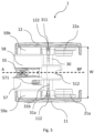
- Fig 5 is a bottom view of the lifting arrangement 1.
- the first and second body side plates 11, 12 are arranged substantially symmetrically around the symmetry plane BP.
- the suspension bolt 30 is provided with pre-drilled holes 31a, b.
- securing pins that goes through adjustment holes 112, 122 in the respective body side plates 11,12, one in each side plate, and down into one of the pre-drilled holes 31a, b in the suspension bolt. These holes are provided so that the width may be easily adjusted upon installation, and they also stop the side plates from moving along the suspension bolt. There may be several pre-drilled holes 31 for the most common widths of the beam 2. And thus, the width may easily be adjusted upon installation.
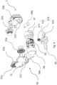
- Fig. 6 shows the lifting arrangement 1 as divided in two halves. Here, the hoist conversion kit is arranged for the specific requirements.
- the suspension bolt 30 is arranged in the bolt receiving hole 111 of the first side plate 11.
- the holder 512 is arranged onto the suspension bolt 30.
- the hoist actuating unit 55 is arranged within the first cover 57, which is arranged onto the first body side plate 11.
- the second cover 58 is arranged to the second side plate 12 by fastening elements 581a-), and similarly the first cover is arranged to the first body side plate.
- the person may grab a half in each hand, bring the two halves together around a beam 2 so that the wheels rest on the respective flanges (2a, 2b), at the same time bring the halves so that the suspension bolt 30 is inserted into the second bolt receiving hole 121 of the second body side plate 12, and the actuating unit 55 is arranged within the second cover 58.
- the adjustment screws are arranged in order to fix the suspension bolt. This is an ergonomic way to provide a lifting arrangement 1 which may be able to hoist a load of 1000 kg.
- the body is preferably made from cast aluminium. In that way, the weight may be kept low and the lifting arrangement 1 may be handled by one single person.
- Fig 7 is a cross sectional view of a lifting arrangement 1 according to the invention.
- the hoist actuating unit 50 is arranged to the right in the picture.
- the hoist actuating unit 50 is located in a cover 57.
- Inside the hoist actuating unit is the internal guide wheel 56.
- the external and internal guide wheels are arranged so that the chain is lead substantially horizontally, at a slight angle. In this way, the lifting arrangement can be kept compact since the hoist actuating unit is arranged as high as possible, and at the same time as close to the external guide wheel as possible.
- the lifting means may have a two fall chain, which doubles the capacity. This means that the free end of the chain is anchored in an anchoring point 514 of the lifting arrangement 1. In this embodiment an anchoring point 514 is located on the holder 512.
- the lifting arrangement 1 By providing the lifting arrangement 1 with such an anchoring point 514 for the chain 5, the hook is arranged on a bend of the chain, and the lifting arrangement may lift the double load compared to if there were no two fall chain and the hook 6 would be arranged directly on the free chain end, which can be viewed in fig. 3 .
- the maximum load is set by the requirements on the hoist actuating unit 50.
- the holder 512 is arranged on the suspension bolt 30.
- the holder 512 is arranged so that the external guide wheel 511 is located so that any collision of the chain and the suspension bolt 30 is prevented.
- the external guide wheel 511 may be arranged in order to keep the centre of gravity as close to the centre of the lifting arrangement 1 as possible.
Landscapes
- Engineering & Computer Science (AREA)
- Mechanical Engineering (AREA)
- Carriers, Traveling Bodies, And Overhead Traveling Cranes (AREA)
- Load-Engaging Elements For Cranes (AREA)
- Lift-Guide Devices, And Elevator Ropes And Cables (AREA)
- Medicines That Contain Protein Lipid Enzymes And Other Medicines (AREA)
Claims (13)
- Lösbarer Hebezeug-Umrüstsatz (50) zur spezifischen Anpassung einer Hubanordnung (1) wie etwa eines Kettenzugs, wobei eine solche Hubanordnung einen Körper (10) mit einer ersten Körperseitenplatte (11), einer zweiten Körperseitenplatte (12), einem Aufhängebolzen (30), der zum Verbinden der ersten und der zweiten Körperseitenplatte (11, 12) angeordnet ist, Hebemittel (5) wie etwa eine Kette, ein Faserseil oder ein Draht, und eine Hebezeugbetätigungseinheit (55) aufweist, die die Hubanordnung betätigt und zum Antreiben der der Hebemittel (5) in einer Anhebe- oder Absenkrichtung verwendet wird, wobei die Hebezeugbetätigungseinheit ein inneres Führungsrad (56) aufweist, das dazu angeordnet ist, das Hebemittel (5) in Längsrichtung durch die Hubanordnung (1) zu führen,
wobei der Hebezeug-Umrüstsatz (50) Folgendes umfasst:eine Führungseinheit (51), die Folgendes umfasst:- einen Halter (512), der zur Anordnung an dem Aufhängebolzen (30) ausgeführt ist, und- ein äußeres Führungsrad (511),wobei das äußere Führungsrad (511) dazu ausgestaltet ist, das Hebemittel (5) intern von der Hebezeugbetätigungseinheit (55) in Längsrichtung durch den Körper zu seiner Anhebestelle (LL), von der aus ein vertikaler Hub möglich ist, zu führen, wobei Längsrichtung als die Richtung der Verlängerung der Symmetrieebene der Hebeanordnung definiert ist, dadurch gekennzeichnet, dass das äußere Führungsrad (511) in dem Halter (512) angeordnet ist, und wobeider Halter (512) ein Loch (513) umfasst, dessen Querschnitt im Wesentlichen gleich dem Querschnitt des Aufhängebolzens (30) ist, und wobei das Loch (513) und der Querschnitt des Aufhängebolzens mindestens eine ebene Fläche aufweisen, um ein Drehen des Halters (512) zu verhindern, wenn dieser an dem Aufhängebolzen (30) angeordnet ist, oderder Halter (512) dazu ausgeführt ist, mittels einer äußeren Befestigungsanordnung wie einer Klammer oder Schraube oder dergleichen an dem Aufhängebolzen (30) angeordnet zu werden. - Lösbarer Hebezeug-Umrüstsatz nach Anspruch 1, ferner umfassend Distanzplatten (59) zum Verstellen der Betriebsbreite (W) der Hubanordnung.
- Hubanordnung (1) zum Anheben einer Last, umfassend einen Körper (10),ein Hebemittel (5) zum vertikalen Anheben wie eine Kette, ein Seil, ein Drahtseil oder ein Faserseil, das durch den Körper zwischen einer Hochhebestelle (HL) und einer Anhebestelle (LL) verläuft,ein Lastverbindungsmittel (6) wie einen Haken zur lösbaren Ineingriffnahme der zu hebenden Last, wobei der Körper (10) Folgendes umfasst:eine erste Körperseitenplatte (11) und eine zweite Körperseitenplatte (12) zur symmetrischen Anordnung um eine Körpersymmetrieebene (BP) herum, wobei sich die Körpersymmetrieebene in einer Längsrichtung in Bezug auf die Hubanordnung erstreckt,einen Aufhängebolzen (30) mit mindestens einer ebenen Fläche, um eine Drehung des Halters (512) zu verhindern, wenn er an dem Aufhängebolzen (30) angeordnet ist, um die erste und die zweite Körperseitenplatte (11, 12) miteinander zu verbinden,eine Hebezeugbetätigungseinheit (55), die die Hubanordnung zum Durchführen des Anhebens und Absenkens betätigt, wobei die Betätigungseinheit (55) zum Betätigen einer Drehung und damit zum Antreiben des Hebemittels (5) in einer Anhebe- oder Absenkrichtung dient, undeinen Hebezeug-Umrüstsatz (50) nach einem der Ansprüche 1 - 2, der dazu angeordnet ist, lösbar an dem Körper (10) angeordnet zu sein,wobei das äußere Führungsrad (511) zum Führen des Hebemittels (5) von seiner Anhebestelle (LL), von der ein vertikales Anheben möglich ist, in Längsrichtung durch den Körper direkt zu einem inneren Führungsrad (56) angeordnet ist, das in der Hebezeugbetätigungseinheit (55) enthalten ist, undwobei die Führungseinheit (51) an dem Aufhängebolzen angeordnet ist.
- Hubanordnung (1) nach Anspruch 3, ferner umfassend: eine erste Abdeckung (57) und eine zweite Abdeckung (58), die zur Aufnahme der Hebezeugbetätigungseinheit (55) angeordnet sind, oder eine erste Fixierungsplatte (57) und eine zweite Fixierungsplatte (58), die zur Fixierung der Hebezeugbetätigungseinheit (55) angeordnet sind, wobei die erste Abdeckung (57) und die zweite Abdeckung (58) oder die erste Fixierungsplatte (57) und die zweite Fixierungsplatte (58) jeweils zum direkten oder indirekten Anordnen an einer jeweiligen Körperseitenplatte (11, 12) angeordnet sind.
- Hubanordnung (1) nach Anspruch 4, wobei die erste (57) und die zweite Abdeckung (58) in den Körper integriert sind.
- Hubanordnung (1) nach einem der Ansprüche 4 oder 5, wobei die Hubanordnung mit einer Laufkatze (20) zur Bewegung entlang der Richtung (A) eines Balkens versehen ist, wobei die Laufkatze (20) einen ersten Satz (21) und einen zweiten Satz (22) symmetrisch angeordneter Räder (21, 22) zur Rollbewegung an einem jeweiligen Flansch des Balkens umfasst.
- Hubanordnung nach Anspruch 6, wobei der erste (21) und der zweite (22) Satz Räder mindestens zwei Räder pro Satz umfassen.
- Hubanordnung (1) nach einem der vorhergehenden Ansprüche 3 - 7, wobei das Hebemittel eine Kette ist und die Hebezeugbetätigungseinheit ein Kettenzug ist.
- Hubanordnung (1) nach Anspruch 8, wobei das äußere Führungsrad (511) und das innere Führungsrad (56) Kettenräder sind, die zur Führung der Kette angeordnet sind.
- Hubanordnung (1) nach Anspruch 6, wobei die erste (11) und die zweite Seitenplatte (12) jeweils ein Bolzenaufnahmeloch (111, 121) umfassen, das mindestens teilweise durch jede der Körperseitenplatten (11, 12) hindurch vorgesehen ist und eine dem Querschnitt des Aufhängebolzens (30) entsprechende Form aufweist, und wobei der Aufhängebolzen (30) in diesem Bolzenaufnahmeloch (111, 112) angeordnet ist.
- Hubanordnung (1) nach einem der Ansprüche 3 - 10, wobei der Hebezeug-Umrüstsatz (50) ferner Distanzplatten umfasst, die zwischen mindestens einer der Abdeckungen und der entsprechenden Seite zu einer beliebigen der Körperseitenplatten hin anzuordnen sind, um die Betriebsbreite (W) der Hubanordnung zu verstellen.
- Verfahren zum Anpassen einer Hubanordnung (1) nach Anspruch 4 durch Verwendung eines Hebezeug-Umrüstsatzes (50) nach einem der Ansprüche 1 - 2, wobei die Hubanordnung (1) mit einer Laufkatze zur Bewegung in der Längsrichtung eines Balkens versehen ist, wobei das Verfahren die folgenden Schritte umfasst:- Bereitstellen des Körpers (10) der Hubanordnung (1), wobei der Körper die erste und die zweite Körperseitenplatte umfasst,- Bereitstellung der Hebezeugbetätigungseinheit (55) der Hubanordnung,- Bereitstellen von Hebemitteln (5) wie einer Kette, eines Seils, eines Drahtseils oder eines Faserseils für das vertikale Anheben,- Bereitstellen des Aufhängebolzens (30), um die erste und die zweite Körperseitenplatte (11, 12) miteinander zu verbinden,- Bereitstellen des Hebezeug-Umrüstsatzes (50) nach einem der Ansprüche 1 - 2,- Anordnen des Halters (512) mit dem äußeren Führungsrad (511) durch Einführen des Aufhängebolzens (30) in das entsprechende Loch (513) des Halters (512) und Befestigen des Aufhängebolzens (30),- Anordnen der Hebezeugbetätigungseinheit in mindestens einer der Abdeckungen, um zu verhindern, dass sich die Hebezeugbetätigungseinheit in der Abdeckung dreht,- Anordnen des Hebemittels (5) so, dass es von der Hebezeugbetätigungseinheit (55) über das äußere Führungsrad (511) geführt wird,- Anordnen der ersten Abdeckung (57) und der zweiten Abdeckung (58) an der ersten Körperseitenplatte (11) bzw. der zweiten Körperseitenplatte (12), so dass sie fest verbunden sind, wobei die Abdeckungen (57, 58) so angeordnet sind, dass tiefste vertikale Punkte (VC1, VC2) der ersten und der zweiten Abdeckung (57, 58) so angeordnet sind, dass sie einem vorbestimmten Soll-D2-Wert entsprechen, wobei der D2-Wert der Abstand von dem tiefsten Punkt der Struktur zu der Oberfläche des Flanschs des Balkens ist, auf dem die Räder der Laufkatze ruhen,- vor dem Anordnen der Abdeckungen (57, 58) gegebenenfalls Anordnen von Distanzplatten (59) zwischen einer oder beiden der ersten und der zweiten Abdeckung und den Körperseitenplatten (11, 12), um die Betriebsbreite (W) der Hubanordnung zu verstellen.
- Verfahren zum Installieren einer Hubanordnung (1) nach Anspruch 10 an einem Querträger (2), wobei das Verfahren die folgenden Schritte umfasst:a. Bereitstellen der Hubanordnung (1), die eine Laufkatze (20) umfasst, die in zwei Hälften auseinandergebaut ist, wobei die erste Hälfte die erste Körperseitenplatte (11) umfasst, wobei die erste Abdeckung (57) an der ersten Körperseitenplatte (11) angeordnet ist, einschließlich der darin angeordneten Hebezeugbetätigungseinheit (55) und den Aufhängebolzen (30), an dem der Halter (512) angeordnet ist, und wobei ein erstes Ende des Aufhängebolzens (30) in ein erstes Bolzenaufnahmeloch (111) in der ersten Körperseitenplatte (11) eingeführt ist und die zweite Hälfte die zweite Körperseitenplatte (12) und die zweite Abdeckung (58) umfasst,b. Anordnen der ersten Hälfte um den Träger herum, so dass der erste Satz Räder (21) auf einem ersten Flansch (2a) ruht,c. Anordnen der zweiten Hälfte um die zweite Seite des Trägers (2), Einführen eines zweiten Endes (32) des Aufhängebolzens (30) in das zweite Bolzenaufnahmeloch (121) in der zweiten Körperseitenplatte (12), so dass der zweite Satz Räder auf dem zweiten Flansch (2b) ruht,d. Verstellen der Betriebsbreite durch Verstellen der Seitenplatten (11, 12) an dem Aufhängebolzen,e. Arretieren der Körperseitenplatten (1) in ihrer Position, indem der Aufhängebolzen (30) durch Befestigungsmittel (311) wie Sicherungsstifte oder Halteschrauben in seiner Position befestigt wird.
Applications Claiming Priority (2)
| Application Number | Priority Date | Filing Date | Title |
|---|---|---|---|
| SE2050763A SE544420C2 (en) | 2020-06-25 | 2020-06-25 | Compact and portable lifting arrangement, conversion kit for a lifting arrangement, and a method to assemble such conversion kit |
| PCT/EP2021/067104 WO2021259979A1 (en) | 2020-06-25 | 2021-06-23 | Compact and portable lifting arrangement, conversion kit for a lifting arrangement, and a method to assemble such conversion kit |
Publications (3)
| Publication Number | Publication Date |
|---|---|
| EP4172097A1 EP4172097A1 (de) | 2023-05-03 |
| EP4172097B1 true EP4172097B1 (de) | 2025-03-26 |
| EP4172097C0 EP4172097C0 (de) | 2025-03-26 |
Family
ID=76744806
Family Applications (1)
| Application Number | Title | Priority Date | Filing Date |
|---|---|---|---|
| EP21736997.4A Active EP4172097B1 (de) | 2020-06-25 | 2021-06-23 | Kompakte und tragbare hebeanordnung, umbausatz für eine hebeanordnung und verfahren zur montage solch eines umbausatzes |
Country Status (4)
| Country | Link |
|---|---|
| EP (1) | EP4172097B1 (de) |
| ES (1) | ES3025139T3 (de) |
| SE (1) | SE544420C2 (de) |
| WO (1) | WO2021259979A1 (de) |
Family Cites Families (13)
| Publication number | Priority date | Publication date | Assignee | Title |
|---|---|---|---|---|
| US2734717A (en) * | 1956-02-14 | campbell | ||
| US3033383A (en) * | 1958-06-19 | 1962-05-08 | Manning Maxwell & Moore Inc | Integrated trolley hoist |
| DE2728740C3 (de) * | 1977-06-25 | 1981-01-29 | Heinrich De Fries Gmbh, 4000 Duesseldorf | Kettenzuglaufkatze |
| DE3710346A1 (de) * | 1987-03-28 | 1988-10-13 | Stahl R Foerdertech Gmbh | Einschienenhaengekatze |
| US5170995A (en) * | 1989-04-04 | 1992-12-15 | Mannesmann Aktiengesellschaft | Easily disassemblable compact hoist |
| US5074423A (en) * | 1989-05-26 | 1991-12-24 | Ingersoll-Rand Company | Low-profile lifting apparatus |
| DE4321758C2 (de) * | 1993-06-30 | 1997-04-10 | Stahl R Foerdertech Gmbh | Einschienenhängekatze mit niedriger Bauhöhe und kurzen Anfahrmaßen |
| DE9319603U1 (de) * | 1993-12-22 | 1995-04-20 | J. D. Neuhaus Hebezeuge Gmbh & Co, 58455 Witten | Laufkatze |
| DE19629785C1 (de) * | 1996-07-24 | 1998-05-07 | Stahl R Foerdertech Gmbh | In der Breite stufenlos verstellbares Katzfahrwerk |
| DE19849995A1 (de) * | 1998-10-30 | 2000-05-11 | Stahl R Foerdertech Gmbh | Hebezeug für Einschienenhängekatze mit niedriger Bauhöhe |
| KR100693379B1 (ko) * | 2004-12-28 | 2007-03-09 | 주식회사 고려호이스트 | 방폭 및 로우헤드형 체인 호이스트 |
| JP3190794U (ja) * | 2014-03-10 | 2014-05-29 | 株式会社神内電機製作所 | ホイスト |
| CN206955470U (zh) * | 2017-04-25 | 2018-02-02 | 浙江手牌起重葫芦有限公司 | 船用超低净空葫芦组合式手动单轨小车 |
-
2020
- 2020-06-25 SE SE2050763A patent/SE544420C2/en unknown
-
2021
- 2021-06-23 EP EP21736997.4A patent/EP4172097B1/de active Active
- 2021-06-23 ES ES21736997T patent/ES3025139T3/es active Active
- 2021-06-23 WO PCT/EP2021/067104 patent/WO2021259979A1/en not_active Ceased
Also Published As
| Publication number | Publication date |
|---|---|
| ES3025139T3 (en) | 2025-06-06 |
| SE2050763A1 (en) | 2021-12-26 |
| EP4172097C0 (de) | 2025-03-26 |
| EP4172097A1 (de) | 2023-05-03 |
| WO2021259979A1 (en) | 2021-12-30 |
| SE544420C2 (en) | 2022-05-17 |
Similar Documents
| Publication | Publication Date | Title |
|---|---|---|
| US7735808B2 (en) | Method and system for performing operations on a wind turbine | |
| CA2997664C (en) | Wind turbine blade removal and installation system and method | |
| US20110042634A1 (en) | Tether hoist systems and apparatuses | |
| CN113184687B (zh) | 一种用于装配式建筑组合板体的适应调整吊装设备 | |
| CN106458549A (zh) | 钢索吊车 | |
| KR20120127393A (ko) | 연결 가능성이 있는 케이블 윈치 | |
| RU2679791C2 (ru) | Подъемник с трубчатым двигателем и раздельным креплением двигателя | |
| CN110615350A (zh) | 一种单点吊装平衡调节装置 | |
| KR20220062580A (ko) | 크레인을 포함하는 결합체와, 크레인에 장착하기 위해 배치된 하중 안내 장치 및 상기 결합체에 사용하기 위한 하중 안내 장치 | |
| WO2000035800A1 (en) | Elevator | |
| CN211444809U (zh) | 一种杠杆式垂直起重机 | |
| WO2021259979A1 (en) | Compact and portable lifting arrangement, conversion kit for a lifting arrangement, and a method to assemble such conversion kit | |
| CN113942927A (zh) | 一种吊装装置 | |
| JP3190794U (ja) | ホイスト | |
| CN220317182U (zh) | 一种建筑结构吊杆装置 | |
| CN219156275U (zh) | 一种钢构横梁的安装举升装置 | |
| CN118324008A (zh) | 一种钢结构吊装装置及施工方法 | |
| CN216737284U (zh) | 一种吊装设备 | |
| CN215854667U (zh) | 一种农业机械设备安装用提升装置 | |
| CN112194019A (zh) | 一种放线滑车自动化拆装维修装置 | |
| CN221680536U (zh) | 一种链条式线缆盘具起吊装置 | |
| CN211078252U (zh) | 一种装配式建筑起重吊 | |
| CN111470407B (zh) | 称杆式吊装组件及吊装设备和吊装方法 | |
| CN220564150U (zh) | 一种锅炉安装用吊运装置 | |
| CN224147615U (zh) | 一种变电站设备基础预埋件吊装平衡架 |
Legal Events
| Date | Code | Title | Description |
|---|---|---|---|
| STAA | Information on the status of an ep patent application or granted ep patent |
Free format text: STATUS: UNKNOWN |
|
| STAA | Information on the status of an ep patent application or granted ep patent |
Free format text: STATUS: THE INTERNATIONAL PUBLICATION HAS BEEN MADE |
|
| PUAI | Public reference made under article 153(3) epc to a published international application that has entered the european phase |
Free format text: ORIGINAL CODE: 0009012 |
|
| STAA | Information on the status of an ep patent application or granted ep patent |
Free format text: STATUS: REQUEST FOR EXAMINATION WAS MADE |
|
| 17P | Request for examination filed |
Effective date: 20230124 |
|
| AK | Designated contracting states |
Kind code of ref document: A1 Designated state(s): AL AT BE BG CH CY CZ DE DK EE ES FI FR GB GR HR HU IE IS IT LI LT LU LV MC MK MT NL NO PL PT RO RS SE SI SK SM TR |
|
| DAV | Request for validation of the european patent (deleted) | ||
| DAX | Request for extension of the european patent (deleted) | ||
| STAA | Information on the status of an ep patent application or granted ep patent |
Free format text: STATUS: EXAMINATION IS IN PROGRESS |
|
| 17Q | First examination report despatched |
Effective date: 20240725 |
|
| GRAP | Despatch of communication of intention to grant a patent |
Free format text: ORIGINAL CODE: EPIDOSNIGR1 |
|
| STAA | Information on the status of an ep patent application or granted ep patent |
Free format text: STATUS: GRANT OF PATENT IS INTENDED |
|
| INTG | Intention to grant announced |
Effective date: 20241022 |
|
| GRAS | Grant fee paid |
Free format text: ORIGINAL CODE: EPIDOSNIGR3 |
|
| GRAA | (expected) grant |
Free format text: ORIGINAL CODE: 0009210 |
|
| STAA | Information on the status of an ep patent application or granted ep patent |
Free format text: STATUS: THE PATENT HAS BEEN GRANTED |
|
| AK | Designated contracting states |
Kind code of ref document: B1 Designated state(s): AL AT BE BG CH CY CZ DE DK EE ES FI FR GB GR HR HU IE IS IT LI LT LU LV MC MK MT NL NO PL PT RO RS SE SI SK SM TR |
|
| REG | Reference to a national code |
Ref country code: GB Ref legal event code: FG4D |
|
| REG | Reference to a national code |
Ref country code: CH Ref legal event code: EP |
|
| REG | Reference to a national code |
Ref country code: DE Ref legal event code: R096 Ref document number: 602021028158 Country of ref document: DE |
|
| REG | Reference to a national code |
Ref country code: IE Ref legal event code: FG4D |
|
| U01 | Request for unitary effect filed |
Effective date: 20250326 |
|
| U07 | Unitary effect registered |
Designated state(s): AT BE BG DE DK EE FI FR IT LT LU LV MT NL PT RO SE SI Effective date: 20250401 |
|
| REG | Reference to a national code |
Ref country code: ES Ref legal event code: FG2A Ref document number: 3025139 Country of ref document: ES Kind code of ref document: T3 Effective date: 20250606 |
|
| U20 | Renewal fee for the european patent with unitary effect paid |
Year of fee payment: 5 Effective date: 20250516 |
|
| PG25 | Lapsed in a contracting state [announced via postgrant information from national office to epo] |
Ref country code: RS Free format text: LAPSE BECAUSE OF FAILURE TO SUBMIT A TRANSLATION OF THE DESCRIPTION OR TO PAY THE FEE WITHIN THE PRESCRIBED TIME-LIMIT Effective date: 20250626 |
|
| PGFP | Annual fee paid to national office [announced via postgrant information from national office to epo] |
Ref country code: MC Payment date: 20250522 Year of fee payment: 5 |
|
| PGFP | Annual fee paid to national office [announced via postgrant information from national office to epo] |
Ref country code: GB Payment date: 20250515 Year of fee payment: 5 |
|
| PGFP | Annual fee paid to national office [announced via postgrant information from national office to epo] |
Ref country code: NO Payment date: 20250516 Year of fee payment: 5 |
|
| PG25 | Lapsed in a contracting state [announced via postgrant information from national office to epo] |
Ref country code: HR Free format text: LAPSE BECAUSE OF FAILURE TO SUBMIT A TRANSLATION OF THE DESCRIPTION OR TO PAY THE FEE WITHIN THE PRESCRIBED TIME-LIMIT Effective date: 20250326 |
|
| PG25 | Lapsed in a contracting state [announced via postgrant information from national office to epo] |
Ref country code: GR Free format text: LAPSE BECAUSE OF FAILURE TO SUBMIT A TRANSLATION OF THE DESCRIPTION OR TO PAY THE FEE WITHIN THE PRESCRIBED TIME-LIMIT Effective date: 20250627 |
|
| PGFP | Annual fee paid to national office [announced via postgrant information from national office to epo] |
Ref country code: TR Payment date: 20250616 Year of fee payment: 5 |
|
| PGFP | Annual fee paid to national office [announced via postgrant information from national office to epo] |
Ref country code: CZ Payment date: 20250617 Year of fee payment: 5 |
|
| PGFP | Annual fee paid to national office [announced via postgrant information from national office to epo] |
Ref country code: IE Payment date: 20250515 Year of fee payment: 5 |
|
| PG25 | Lapsed in a contracting state [announced via postgrant information from national office to epo] |
Ref country code: SM Free format text: LAPSE BECAUSE OF FAILURE TO SUBMIT A TRANSLATION OF THE DESCRIPTION OR TO PAY THE FEE WITHIN THE PRESCRIBED TIME-LIMIT Effective date: 20250326 |
|
| PGFP | Annual fee paid to national office [announced via postgrant information from national office to epo] |
Ref country code: ES Payment date: 20250701 Year of fee payment: 5 |
|
| PGFP | Annual fee paid to national office [announced via postgrant information from national office to epo] |
Ref country code: CH Payment date: 20250701 Year of fee payment: 5 |
|
| PG25 | Lapsed in a contracting state [announced via postgrant information from national office to epo] |
Ref country code: SK Free format text: LAPSE BECAUSE OF FAILURE TO SUBMIT A TRANSLATION OF THE DESCRIPTION OR TO PAY THE FEE WITHIN THE PRESCRIBED TIME-LIMIT Effective date: 20250326 |
|
| PG25 | Lapsed in a contracting state [announced via postgrant information from national office to epo] |
Ref country code: IS Free format text: LAPSE BECAUSE OF FAILURE TO SUBMIT A TRANSLATION OF THE DESCRIPTION OR TO PAY THE FEE WITHIN THE PRESCRIBED TIME-LIMIT Effective date: 20250726 |
|
| PLBE | No opposition filed within time limit |
Free format text: ORIGINAL CODE: 0009261 |
|
| STAA | Information on the status of an ep patent application or granted ep patent |
Free format text: STATUS: NO OPPOSITION FILED WITHIN TIME LIMIT |
|
| REG | Reference to a national code |
Ref country code: CH Ref legal event code: L10 Free format text: ST27 STATUS EVENT CODE: U-0-0-L10-L00 (AS PROVIDED BY THE NATIONAL OFFICE) Effective date: 20260211 |
|
| 26N | No opposition filed |
Effective date: 20260105 |