EP4168673B1 - Hubkolbenpumpe zum fördern eines mediums - Google Patents
Hubkolbenpumpe zum fördern eines mediums Download PDFInfo
- Publication number
- EP4168673B1 EP4168673B1 EP21733091.9A EP21733091A EP4168673B1 EP 4168673 B1 EP4168673 B1 EP 4168673B1 EP 21733091 A EP21733091 A EP 21733091A EP 4168673 B1 EP4168673 B1 EP 4168673B1
- Authority
- EP
- European Patent Office
- Prior art keywords
- reciprocating piston
- auxiliary
- cylinder
- drive
- pump
- Prior art date
- Legal status (The legal status is an assumption and is not a legal conclusion. Google has not performed a legal analysis and makes no representation as to the accuracy of the status listed.)
- Active
Links
Images

Classifications
-
- F—MECHANICAL ENGINEERING; LIGHTING; HEATING; WEAPONS; BLASTING
- F04—POSITIVE - DISPLACEMENT MACHINES FOR LIQUIDS; PUMPS FOR LIQUIDS OR ELASTIC FLUIDS
- F04B—POSITIVE-DISPLACEMENT MACHINES FOR LIQUIDS; PUMPS
- F04B15/00—Pumps adapted to handle specific fluids, e.g. by selection of specific materials for pumps or pump parts
- F04B15/02—Pumps adapted to handle specific fluids, e.g. by selection of specific materials for pumps or pump parts the fluids being viscous or non-homogeneous
-
- F—MECHANICAL ENGINEERING; LIGHTING; HEATING; WEAPONS; BLASTING
- F04—POSITIVE - DISPLACEMENT MACHINES FOR LIQUIDS; PUMPS FOR LIQUIDS OR ELASTIC FLUIDS
- F04B—POSITIVE-DISPLACEMENT MACHINES FOR LIQUIDS; PUMPS
- F04B3/00—Machines or pumps with pistons coacting within one cylinder, e.g. multi-stage
- F04B3/003—Machines or pumps with pistons coacting within one cylinder, e.g. multi-stage with two or more pistons reciprocating one within another, e.g. one piston forning cylinder of the other
-
- F—MECHANICAL ENGINEERING; LIGHTING; HEATING; WEAPONS; BLASTING
- F04—POSITIVE - DISPLACEMENT MACHINES FOR LIQUIDS; PUMPS FOR LIQUIDS OR ELASTIC FLUIDS
- F04B—POSITIVE-DISPLACEMENT MACHINES FOR LIQUIDS; PUMPS
- F04B13/00—Pumps specially modified to deliver fixed or variable measured quantities
- F04B13/02—Pumps specially modified to deliver fixed or variable measured quantities of two or more fluids at the same time
-
- F—MECHANICAL ENGINEERING; LIGHTING; HEATING; WEAPONS; BLASTING
- F04—POSITIVE - DISPLACEMENT MACHINES FOR LIQUIDS; PUMPS FOR LIQUIDS OR ELASTIC FLUIDS
- F04B—POSITIVE-DISPLACEMENT MACHINES FOR LIQUIDS; PUMPS
- F04B15/00—Pumps adapted to handle specific fluids, e.g. by selection of specific materials for pumps or pump parts
- F04B15/04—Pumps adapted to handle specific fluids, e.g. by selection of specific materials for pumps or pump parts the fluids being hot or corrosive
-
- F—MECHANICAL ENGINEERING; LIGHTING; HEATING; WEAPONS; BLASTING
- F04—POSITIVE - DISPLACEMENT MACHINES FOR LIQUIDS; PUMPS FOR LIQUIDS OR ELASTIC FLUIDS
- F04B—POSITIVE-DISPLACEMENT MACHINES FOR LIQUIDS; PUMPS
- F04B19/00—Machines or pumps having pertinent characteristics not provided for in, or of interest apart from, groups F04B1/00 - F04B17/00
- F04B19/20—Other positive-displacement pumps
- F04B19/22—Other positive-displacement pumps of reciprocating-piston type
-
- F—MECHANICAL ENGINEERING; LIGHTING; HEATING; WEAPONS; BLASTING
- F04—POSITIVE - DISPLACEMENT MACHINES FOR LIQUIDS; PUMPS FOR LIQUIDS OR ELASTIC FLUIDS
- F04B—POSITIVE-DISPLACEMENT MACHINES FOR LIQUIDS; PUMPS
- F04B49/00—Control, e.g. of pump delivery, or pump pressure of, or safety measures for, machines, pumps, or pumping installations, not otherwise provided for, or of interest apart from, groups F04B1/00 - F04B47/00
- F04B49/12—Control, e.g. of pump delivery, or pump pressure of, or safety measures for, machines, pumps, or pumping installations, not otherwise provided for, or of interest apart from, groups F04B1/00 - F04B47/00 by varying the length of stroke of the working members
- F04B49/123—Control, e.g. of pump delivery, or pump pressure of, or safety measures for, machines, pumps, or pumping installations, not otherwise provided for, or of interest apart from, groups F04B1/00 - F04B47/00 by varying the length of stroke of the working members by changing the eccentricity of one element relative to another element
- F04B49/125—Control, e.g. of pump delivery, or pump pressure of, or safety measures for, machines, pumps, or pumping installations, not otherwise provided for, or of interest apart from, groups F04B1/00 - F04B47/00 by varying the length of stroke of the working members by changing the eccentricity of one element relative to another element by changing the eccentricity of the actuation means, e.g. cams or cranks, relative to the driving means, e.g. driving shafts
-
- F—MECHANICAL ENGINEERING; LIGHTING; HEATING; WEAPONS; BLASTING
- F04—POSITIVE - DISPLACEMENT MACHINES FOR LIQUIDS; PUMPS FOR LIQUIDS OR ELASTIC FLUIDS
- F04B—POSITIVE-DISPLACEMENT MACHINES FOR LIQUIDS; PUMPS
- F04B5/00—Machines or pumps with differential-surface pistons
- F04B5/02—Machines or pumps with differential-surface pistons with double-acting pistons
-
- F—MECHANICAL ENGINEERING; LIGHTING; HEATING; WEAPONS; BLASTING
- F04—POSITIVE - DISPLACEMENT MACHINES FOR LIQUIDS; PUMPS FOR LIQUIDS OR ELASTIC FLUIDS
- F04B—POSITIVE-DISPLACEMENT MACHINES FOR LIQUIDS; PUMPS
- F04B53/00—Component parts, details or accessories not provided for in, or of interest apart from, groups F04B1/00 - F04B23/00 or F04B39/00 - F04B47/00
- F04B53/14—Pistons, piston-rods or piston-rod connections
- F04B53/142—Intermediate liquid-piston between a driving piston and a driven piston
-
- F—MECHANICAL ENGINEERING; LIGHTING; HEATING; WEAPONS; BLASTING
- F04—POSITIVE - DISPLACEMENT MACHINES FOR LIQUIDS; PUMPS FOR LIQUIDS OR ELASTIC FLUIDS
- F04B—POSITIVE-DISPLACEMENT MACHINES FOR LIQUIDS; PUMPS
- F04B53/00—Component parts, details or accessories not provided for in, or of interest apart from, groups F04B1/00 - F04B23/00 or F04B39/00 - F04B47/00
- F04B53/14—Pistons, piston-rods or piston-rod connections
- F04B53/143—Sealing provided on the piston
-
- F—MECHANICAL ENGINEERING; LIGHTING; HEATING; WEAPONS; BLASTING
- F04—POSITIVE - DISPLACEMENT MACHINES FOR LIQUIDS; PUMPS FOR LIQUIDS OR ELASTIC FLUIDS
- F04B—POSITIVE-DISPLACEMENT MACHINES FOR LIQUIDS; PUMPS
- F04B53/00—Component parts, details or accessories not provided for in, or of interest apart from, groups F04B1/00 - F04B23/00 or F04B39/00 - F04B47/00
- F04B53/18—Lubricating
Definitions
- the invention relates to a reciprocating piston pump for conveying a medium.
- the reciprocating piston pump has at least one pump module and a drive.
- the drive is designed to drive the at least one pump module so that the at least one pump module pumps a medium during operation. See DE102016210728 A1 with a pump that is at least structurally similar.
- the reciprocating piston pump is used to supply devices with power, whereby the power is transmitted via a medium that is pressurized by the reciprocating piston pump when pumping. During operation, the reciprocating piston pump generates a pressure in the medium of more than 160 bar.
- the reciprocating piston pump and the devices to be supplied are connected, for example, to a hydraulic circuit to transmit the power.
- the at least one pump module has a cylinder head, a cylinder and a reciprocating piston, wherein the reciprocating piston has a reciprocating piston base with a reciprocating piston base surface.
- the cylinder head, the cylinder and the reciprocating piston base form a delivery volume. In other words, the cylinder head, the cylinder and the reciprocating piston base enclose the delivery volume.
- the reciprocating piston is designed to convert a drive movement of the drive into a delivery stroke movement and a suction stroke movement of the reciprocating piston in the cylinder along a longitudinal axis. Accordingly, the delivery volume is not constant: The delivery volume is reduced when the reciprocating piston approaches the cylinder head during the delivery stroke movement. At the same time, a pressure in a medium located in the delivery volume increases. The delivery volume is increased when the reciprocating piston moves away from the cylinder head during the suction stroke movement. At the same time, a pressure in a medium located in the delivery volume decreases.
- the cylinder head, the cylinder and the piston are designed to convert the delivery stroke movement into a conveyance of a medium from the delivery volume by reducing the delivery volume. Usually they are also designed to convert the suction stroke movement into a suction of a medium into the delivery volume by increasing the delivery volume.
- the design of the cylinder head includes, for example, a cylinder head control, which ensures that a medium flows into the delivery volume during the suction stroke movement and that a medium flows out of the delivery volume during the delivery stroke movement.
- the cylinder head control has, for example, an inflow and an outflow valve.
- the design of the cylinder and piston includes, for example, that they seal tightly against one another, so that the pressure in a medium in the delivery volume increases during the delivery stroke movement and decreases during the suction stroke movement.
- the reciprocating piston pump is designed to pump media that have a lower viscosity than lubricating media.
- Such media include HFA and HFC media, water-glycol mixtures and also water. It is therefore also designed to pump media that are corrosive. It is also designed to pump media with particles, i.e. media that are abrasive.
- the reciprocating piston pump is designed to generate pressures during the delivery stroke movement at which media are no longer suitable for lubricating contact surfaces between the cylinder and the reciprocating piston and bearings in the drive.
- Such pressures are, for example, more than 150 bar.
- these contact surfaces and bearings must be lubricated with a lubricant that is different from the media, and a media separation between the media on the one hand and the lubricant on the other must be implemented.
- the media separation must ensure that no leakage of the medium into the lubricant medium occurs. Leakage of the medium into the lubricant medium leads to a deterioration of the lubricating properties of the lubricant medium, which means that lubrication of the contact surfaces and bearings is no longer guaranteed and the contact surfaces and bearings are damaged. Conversely, a slight leakage of the lubricant medium into the medium is tolerable.
- the media separation is implemented by a stuffing box seal between the piston and the cylinder.
- the stuffing box seal In order for the stuffing box seal to seal the cylinder and the piston sufficiently tightly, the stuffing box seal must be saturated with the medium.
- ensuring that the medium is saturated with the medium also inevitably leads to the medium leaking into the lubricating medium, so that the lubricating medium must be replaced at intervals depending on the concentration of the medium in the lubricating medium.
- Another disadvantage is that the sealing surface of the stuffing box seal is large and requires correspondingly high friction forces, which must be applied by the drive. Furthermore, the sealing surface cannot be controlled.
- an elastomer seal is used. In order to reduce wear on the elastomer seal, it must be cooled. The medium is used for this purpose, but this requires a small amount of leakage past the elastomer seal. This means that even when an elastomer seal is used, the medium penetrates into the lubricating medium. Furthermore, the frequency of the delivery stroke and suction stroke movement is limited to a maximum frequency due to the viscoelastic properties of the elastomer seal.
- the piston and the delivery volume are separated from each other by a membrane.
- the delivery volume is formed by the cylinder head, the cylinder and the membrane. This implementation ensures complete media separation, which is why no leakage occurs.
- the membrane follows the delivery stroke and suction stroke movement of the piston. However, the membrane rubs against the piston and the cylinder, causing it to wear out and eventually have to be replaced.
- the object of the present invention is to provide a reciprocating piston pump with a media separation which at least reduces the disadvantages of the prior art.
- the reciprocating piston pump has an auxiliary reciprocating piston.
- the auxiliary reciprocating piston is arranged between the drive and the reciprocating piston and has an auxiliary reciprocating piston base with an auxiliary reciprocating piston base surface.
- the cylinder, the reciprocating piston and the auxiliary reciprocating piston base form a lubricating volume for a lubricating medium for lubricating contact surfaces between the cylinder on the one hand and the reciprocating piston and the auxiliary reciprocating piston on the other hand.
- the cylinder, the reciprocating piston and the auxiliary reciprocating piston base enclose the lubricating volume.
- the cylinder, the reciprocating piston and the auxiliary reciprocating piston are designed to convert the drive movement into an auxiliary delivery stroke movement and into an auxiliary suction stroke movement of the auxiliary reciprocating piston in the cylinder along the longitudinal axis and the auxiliary delivery stroke movement of the auxiliary reciprocating piston into the delivery stroke movement of the reciprocating piston via a lubricating medium in the lubricating volume.
- both the reciprocating piston and the auxiliary reciprocating piston move over sections of the cylinder that were previously in direct contact with a lubricating medium, whereby the contact surfaces between the cylinder and the reciprocating piston on the one hand and the cylinder and the auxiliary reciprocating piston on the other hand are lubricated with the lubricating medium.
- the auxiliary piston bottom area is smaller than the reciprocating piston bottom area, so that during the auxiliary delivery stroke movement, a pressure of a lubricating medium in the lubricating volume is greater than a pressure of a medium in the delivery volume.
- the pressure in the lubricating medium is greater than the pressure in the medium because the auxiliary piston bottom area is smaller than the reciprocating piston bottom area.
- the pressure in the lubricating medium in the lubricating volume is greater than the pressure in the medium in the delivery volume, leakage only occurs from the lubricating volume into the delivery volume and towards the drive. While leakage towards the drive is not a problem, leakage into the delivery volume is tolerable. In any case, no medium penetrates the lubricant, so the lubricating properties of the lubricant do not deteriorate.
- the cylinder has an inner cylinder surface concentric to the longitudinal axis with a cylinder radius
- the reciprocating piston has an outer cylinder surface concentric to the longitudinal axis with a reciprocating piston radius
- the auxiliary reciprocating piston has an auxiliary reciprocating piston outer cylinder surface concentric to the longitudinal axis with an auxiliary reciprocating piston radius. It is further provided that both the reciprocating piston radius and the auxiliary reciprocating piston radius match the cylinder radius.
- the cylinder radius has a first value over a first distance along the longitudinal axis and a second value over a second distance along the longitudinal axis that is smaller than the first value. Then the reciprocating piston radius has a value that matches the first value and the auxiliary reciprocating piston radius has a value that matches the second value.
- the first distance extends over the delivery and suction stroke movement of the reciprocating piston and the second distance extends over the auxiliary delivery and auxiliary suction stroke movement of the auxiliary reciprocating piston.
- the reciprocating piston radius and the auxiliary reciprocating piston radius are the same.
- the cylinder radius has the same value over the first and second sections and the reciprocating piston radius and the auxiliary reciprocating piston radius have a value that matches the value.
- the pressure in the lubricating medium in the lubricating volume is higher than the pressure in the medium in the delivery volume.
- a reduction in the auxiliary piston base area compared to the piston base area is implemented in a further embodiment by the piston having a relief piston and the auxiliary piston in the auxiliary piston base having a relief cylinder to match the relief piston and in that the relief cylinder has a relief volume and/or is connected to a relief volume.
- the relief piston is a shaft.
- the lubrication volume decreases, which is why the piston distance between the reciprocating piston and the auxiliary reciprocating piston becomes smaller and the auxiliary delivery stroke movement is greater than the delivery stroke movement.
- the reduction in the piston distance causes the relief piston to move into the relief cylinder. This increases the pressure in the relief volume.
- the relief volume is formed, for example, by the relief piston and the relief cylinder. This increase in pressure counteracts the reduction in the auxiliary piston base area compared to the piston base area. It is therefore advantageous to choose the relief volume as large as possible.
- the relief volume is preferably the environment, so that there is practically no increase in pressure in the relief volume.
- the auxiliary reciprocating piston has a relief line which connects the relief cylinder with the environment.
- the relief piston and the relief cylinder limit a piston distance between the reciprocating piston and the auxiliary reciprocating piston along the longitudinal axis to a maximum piston distance.
- the limitation of the piston distance means that the lubrication volume is also limited to a maximum lubricating medium volume. Without limiting the piston distance, there is a possibility that the reciprocating piston will hit the cylinder head during the delivery stroke movement and the reciprocating piston pump will be damaged.
- the reciprocating piston pump has a bearing and that the bearing is arranged between the drive and the auxiliary reciprocating piston. Furthermore, the bearing is designed to convert the drive movement of the drive into the auxiliary delivery stroke movement and the auxiliary suction stroke movement of the auxiliary reciprocating piston.
- the drive has a drive shaft. It is also provided that the drive shaft has a drive eccentric with an eccentric sliding surface and the auxiliary piston has an auxiliary piston sliding surface.
- the Eccentric sliding surface and the auxiliary piston sliding surface the bearing.
- the drive shaft and the auxiliary piston are designed to convert the drive movement of the drive shaft in the form of a rotation via the bearing into the auxiliary delivery stroke movement and the auxiliary suction stroke movement.
- the drive shaft without a drive eccentric is usually designed as a crankshaft with a crank pin, whereby the crank pin is arranged rotatably in the drive eccentric.
- a rotary movement of the drive eccentric is prevented by an eccentric shape of the eccentric sliding surface in conjunction with the resting auxiliary piston sliding surface.
- An alternative to this is a drive shaft with an eccentric pin, whereby the eccentric pin is arranged rotatably in the drive eccentric.
- the eccentric sliding surface and the auxiliary piston sliding surface have a common contact surface, via which the rotation of the drive shaft is converted into the auxiliary delivery and suction stroke movement.
- the eccentric and auxiliary piston sliding surfaces form the bearing.
- the common contact surface must be lubricated with a lubricant to reduce wear on the eccentric and auxiliary piston sliding surfaces.
- the bearing is designed for a lubricant that is also suitable for the contact surfaces between the cylinder on the one hand and the reciprocating piston and auxiliary piston on the other.
- the auxiliary reciprocating piston has an auxiliary reciprocating piston lubrication line, and the auxiliary reciprocating piston lubrication line connects the lubrication volume and the auxiliary reciprocating piston sliding surface to supply the bearing with a lubricating medium.
- the bearing is lubricated with the lubricating medium, which is also used to lubricate the contact surfaces between the cylinder on the one hand and the reciprocating piston and the auxiliary reciprocating piston on the other.
- a lubricating medium is supplied to the bearing at a pressure that is established in the delivery volume during the delivery stroke movement.
- the auxiliary piston lubricating medium line is preferably a channel in the auxiliary reciprocating piston. In this case, there is no separate lubricating medium line.
- the auxiliary piston lubrication line has at least one check valve.
- the check valve prevents the lubricant from leaking out of the bearing. Without the check valve, this leakage would occur during the suction stroke movement, for example.
- the reciprocating piston pump has a longitudinal slide valve for controlling the supply of a lubricating medium into the lubricating volume.
- the longitudinal slide valve has at least one cylinder opening in the cylinder for supplying a lubricating medium into the lubricating volume.
- the at least one cylinder opening is a groove, pocket and/or bore. The function of a valve is inherently achieved either by the delivery and suction stroke movement of the reciprocating piston or by the auxiliary delivery and auxiliary suction stroke movement of the auxiliary piston past the at least one cylinder opening in the cylinder.
- the auxiliary piston lubrication line described above is also implemented.
- the contact surfaces between the cylinder on the one hand and the piston and the auxiliary piston on the other hand, but also the bearing are lubricated with a lubricating medium that can be supplied via the longitudinal slide valve.
- the at least one cylinder opening releases a supply of a lubricating medium to the lubricating volume when the reciprocating piston is in the region of a reversal point from the suction stroke movement to the delivery stroke movement.
- a pressure in the lubricating volume is at its lowest, so that the supply of a lubricating medium is most effective.
- the drive shaft has a drive lubrication line.
- the drive lubrication line therefore extends both through the drive shaft itself and through the drive eccentric of the drive shaft.
- the drive shaft also has a rotary slide valve for controlling the supply of a lubricant to the bearing.
- the rotary slide valve has a drive shaft recess in the drive shaft via a Angular range of rotation of the drive shaft, so that a lubricant is only supplied to the bearing over the angular range.
- the drive lubrication line is a channel in the drive shaft and in the drive eccentric. Then there is no separate lubricant line.
- the rotary slide valve is usually formed by the drive shaft recess and the drive lubrication line in the eccentric. The rotary slide valve also ensures that a lubricant is supplied to contact surfaces between the drive shaft and the drive eccentric.
- the drive lubrication line has at least one check valve.
- the check valve prevents the lubricant in the bearing from running off.
- the auxiliary piston lubrication line described above is also implemented.
- not only the bearing, but also the contact surfaces between the cylinder on the one hand and the piston and the auxiliary piston on the other hand are lubricated with a lubricating medium which can be supplied via the drive lubrication line.
- the reciprocating piston pump has a lubricating pump for supplying the at least one pump module and/or the drive with a lubricating medium.
- the reciprocating piston pump is designed to supply a lubricating medium from the lubricating pump to the longitudinal slide valve and in embodiments with the previously described drive lubrication line, it is designed to supply a lubricating medium from the lubricating pump to the drive lubrication line.
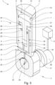
- Fig. 1 shows a first embodiment of a reciprocating piston pump 1 for conveying a medium. It has a pump module 2, a drive 3, a bearing 4 and a lubricating pump 5.
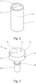
- the pump module 2 has a cylinder head 6, a cylinder 7, see also Fig. 2 , a reciprocating piston 8, see also Fig. 3 , and an auxiliary piston 9, see also Fig. 4a, 4b , on.
- the cylinder 7 has a cylinder inner surface 11 concentric with a longitudinal axis 10 and with a cylinder radius 12.
- the reciprocating piston 8 has a reciprocating piston base 13 with a reciprocating piston base surface 14 and a reciprocating piston outer surface 15 concentric with the longitudinal axis 10 and with a reciprocating piston radius 16.
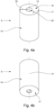
- the auxiliary reciprocating piston 9 is arranged between the drive 3 and the reciprocating piston 8, has an auxiliary reciprocating piston base 17 with an auxiliary reciprocating piston base surface 18, an auxiliary reciprocating piston outer surface 19 concentric with the longitudinal axis 10 and with an auxiliary reciprocating piston radius 20 and an auxiliary reciprocating piston sliding surface 21.
- the reciprocating piston radius 16 and the auxiliary reciprocating piston radius 20 are the same and match the cylinder radius 12.
- the lifting piston 8 has a relief lifting piston 22 and the auxiliary lifting piston 9 in the auxiliary lifting piston base 17 has a relief cylinder 23 matching the relief lifting piston 22.
- the relief cylinder 23 is connected to the environment as a relief volume via a relief line 24.
- the relief lifting piston 22 is a shaft in this embodiment.
- the relief piston 22 and the relief cylinder 23 limit a piston distance 25 between the lifting piston 8 and the auxiliary lifting piston 9 along the longitudinal axis 10 to a maximum piston distance.
- the relief piston 22 has a ring 26 and the relief cylinder 23 has a groove 27 that matches the ring 26.
- the lifting piston 8 and the auxiliary lifting piston 9 can be moved relative to one another along the longitudinal axis 10 in accordance with the ring 26 and the groove 7.
- the drive 3 has a drive shaft 28 and the drive shaft 28 has a drive eccentric 29 with an eccentric sliding surface 30.
- the drive shaft 28 without the drive eccentric 29 is designed as a crankshaft with a crank pin 31, wherein the crank pin 31 is arranged rotatably in the drive eccentric 29.
- a rotary movement of the drive eccentric 29 is prevented by an eccentric shape of the eccentric sliding surface 30 in conjunction with the auxiliary piston sliding surface 21 resting thereon.
- the eccentric sliding surface 30 and the auxiliary lifting piston sliding surface 21 form the bearing 4.
- the bearing 4 is arranged between the drive 3 and the auxiliary lifting piston 9.
- the drive shaft 28 with the drive eccentric 29 and the auxiliary lifting piston 9 are designed to convert a drive movement 32 of the drive shaft 28 in the form of a rotation via the bearing 4 into an auxiliary delivery stroke movement 33 and into an auxiliary suction stroke movement 34 of the auxiliary lifting piston 9 in the cylinder 7 along the longitudinal axis 10.
- the bearing 4 is thus designed to convert the drive movement 32 into the auxiliary delivery stroke movement 33 and into the auxiliary suction stroke movement 34.
- the cylinder head 6, the cylinder 7 and the piston base 9 form a delivery volume 35. Furthermore, the cylinder 7, the piston 8 and the auxiliary piston base 17 form a lubrication volume 36 for a lubricating medium for lubricating contact surfaces between the cylinder 7 on the one hand and the piston 8 and the auxiliary piston 9 on the other.
- the contact surfaces in this embodiment are, on the one hand, the cylinder inner surface 11 and the piston outer surface 15 and, on the other hand, the cylinder inner surface 11 and the auxiliary piston outer surface 19.
- the cylinder 7, the reciprocating piston 8 and the auxiliary reciprocating piston 9 are designed to convert the drive movement 32 into the auxiliary delivery stroke movement 33 and into the auxiliary suction stroke movement 34 of the auxiliary piston 9 in the cylinder 7 along the longitudinal axis 10 and also the auxiliary delivery stroke movement 33 of the Auxiliary lifting piston 9 is to be converted into a delivery stroke movement 37 of the lifting piston 8 in the cylinder 7 along the longitudinal axis 10 via a lubricating medium in the lubricating volume 36.
- the cylinder 7, the lifting piston 8 and the auxiliary lifting piston 9 are further designed to convert the auxiliary suction stroke movement 34 of the auxiliary piston 9 into a suction stroke movement 3 of the lifting piston 8 in the cylinder 7 along the longitudinal axis 10 via a lubricating medium in the lubricating volume 36.
- the reciprocating piston 8 is designed to convert the drive movement 32 of the drive 3 into the delivery stroke movement 37 and the suction stroke movement 38 of the reciprocating piston 8 in the cylinder 7 along the longitudinal axis 10.
- the cylinder head 6, the cylinder 7 and the reciprocating piston 8 are designed to convert the delivery stroke movement 37 of the reciprocating piston 8 into a delivery of a medium from the delivery volume 35 by reducing the delivery volume 35.
- the cylinder head 6 has a cylinder head control which ensures that a medium flows into the delivery volume 35 during the suction stroke movement 38 and that a medium flows out of the delivery volume 35 during the delivery stroke movement 37.
- the cylinder head control has an inflow and an outflow valve. Neither the cylinder head control nor the inflow and outflow valve are shown.
- the cylinder head 6, the cylinder 7 and the reciprocating piston 8 are also designed to convert the suction stroke movement 38 into a suction of a medium into the delivery volume 35 by increasing the delivery volume 35.
- the auxiliary piston base surface 18 is smaller than the piston base surface 14 because the auxiliary piston base surface 18, in contrast to the piston base surface 14, lacks a cross-sectional area of the relief cylinder 23.
- a pressure of a lubricant in the lubricant volume 36 is greater than a pressure of a medium in the delivery volume 35, which results from the delivery stroke movement 37 of the piston 8.
- the auxiliary piston 9 has an auxiliary piston lubrication line 39.
- the auxiliary piston lubrication line 39 connects the lubrication volume 36 and the auxiliary piston sliding surface 21 to one another to supply the bearing 4 with a lubricating medium.
- the auxiliary piston lubrication line 39 is a channel in the auxiliary piston 9.
- the drive eccentric 29 has an auxiliary lubrication line which connects the eccentric sliding surface 30 with contact surfaces between the crank pin 31 and the drive eccentric 29, so that these contact surfaces are also supplied with a lubricant during operation.
- this auxiliary lubrication line is not shown here.
- the reciprocating piston pump 1 also has a longitudinal slide valve 40 for controlling the supply of a lubricating medium into the lubricating volume 36.
- the longitudinal slide valve 40 has a cylinder opening 41 in the cylinder 7 for supplying a lubricating medium into the lubricating volume 36.
- the cylinder opening 41 is a bore. The cylinder opening enables the supply of a lubricating medium into the lubricating volume 36 when the reciprocating piston 8 is in the region of a reversal point from the suction stroke movement 38 to the delivery stroke movement 37.
- the lubrication pump 5 is designed to supply the pump module 2 and the drive 3 with a lubricating medium and the reciprocating piston pump 1 is designed to supply a lubricating medium from the lubrication pump 5 to the longitudinal slide valve 40.
- the auxiliary reciprocating piston lubrication line 39 not only supplies the contact surfaces between the cylinder 7 on the one hand and the reciprocating piston 8 and the auxiliary reciprocating piston 9 on the other hand, but also the bearing 4 with a lubricating medium for lubrication.
- the bearing 4 is supplied from the lubrication volume 36 via the auxiliary reciprocating piston lubrication line 39.
- Fig. 5 shows a second embodiment of a reciprocating piston pump 1 for conveying a medium. Only the differences to the first embodiment are described below. Otherwise, the statements for the first embodiment apply analogously to the second embodiment.
- the reciprocating piston pump 1 does not have the described longitudinal slide valve 40. Instead, the drive shaft 28 has a drive lubrication line 42.
- the drive lubrication line 42 therefore extends through the drive shaft 28 itself as well as through the drive eccentric 29.
- the part of the drive lubrication line 42 in the drive eccentric 29 therefore corresponds to that of the auxiliary lubrication line in the first embodiment.
- the drive shaft 28 has a rotary slide valve 43 for controlling the supply of a lubricating medium into the bearing 4.
- the rotary slide valve 43 has a drive shaft recess 44 in the drive shaft 28. over an angular range of rotation of the drive shaft 28, whereby a lubricant is only supplied to the bearing 4 over the angular range.
- the drive lubrication line 42 is a channel in the drive shaft 28 and in the drive eccentric 29.
- the rotary slide valve 43 is formed by the drive shaft recess 44 and the drive lubrication line 42 in the eccentric 29.
- the rotary slide valve 43 also ensures that a lubricant is supplied to contact surfaces between the drive shaft 28 and the drive eccentric 29.
- the lubrication pump 5 is designed to supply the pump module 2 and the drive 3 with a lubricating medium
- the reciprocating piston pump 1 is designed to supply a lubricating medium from the lubrication pump 5 to the drive lubrication line 42.
- the reciprocating piston pump 1 not only the bearing 4 is supplied with a lubricating medium through the drive lubrication line 42 and the auxiliary reciprocating piston lubrication line 39, but also the contact surfaces between the cylinder 7 on the one hand and the reciprocating piston 8 and the auxiliary reciprocating piston 9 on the other.
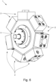
- Fig. 6 shows a third embodiment of a reciprocating piston pump 1. In contrast to the first and second embodiments, it has a plurality of pump modules 2. Otherwise, the reciprocating piston pump 1 is designed like the reciprocating piston pump described in the first or second embodiment.
Landscapes
- Engineering & Computer Science (AREA)
- Mechanical Engineering (AREA)
- General Engineering & Computer Science (AREA)
- Details Of Reciprocating Pumps (AREA)
- Reciprocating Pumps (AREA)
Description
- Die Erfindung betrifft eine Hubkolbenpumpe zum Fördern eines Mediums.
- Die Hubkolbenpumpe weist zum einen mindestens ein Pumpmodul und zum anderen einen Antrieb auf. Der Antrieb ist ausgebildet, das mindestens eine Pumpmodul anzutreiben, sodass das mindestens eine Pumpmodul im Betrieb ein Medium fördert. Siehe
DE102016210728 A1 mit einer zumindest strukturell ähnlichen Pumpe. - Die Hubkolbenpumpe dient der Versorgung von Geräten mit Leistung, wobei die Leistung über ein Medium übertragen wird, das von der Hubkolbenpumpe dazu beim Fördern unter Druck gesetzt wird. Die Hubkolbenpumpe erzeugt im Betrieb einen Druck im Medium von mehr als 160 bar. Die Hubkolbenpumpe und zu versorgende Geräte werden zum Beispiel an einen hydraulischen Kreis zur Übertragung der Leistung angeschlossen.
- Das mindestens eine Pumpmodul weist einen Zylinderkopf, einen Zylinder und einen Hubkolben auf, wobei der Hubkolben einen Hubkolben-Boden mit einer Hubkolben-Bodenfläche aufweist. Der Zylinderkopf, der Zylinder und der Hubkolben-Boden bilden ein Fördervolumen. Mit anderen Worten umschließen der Zylinderkopf, der Zylinder und der Hubkolben-Boden das Fördervolumen.
- Der Hubkolben ist ausgebildet, eine Antriebsbewegung des Antriebs in eine Förderhubbewegung und in eine Saughubbewegung des Hubkolbens im Zylinder entlang einer Längsachse umzusetzen. Demnach ist das Fördervolumen nicht konstant: Das Fördervolumen wird verringert, wenn sich der Hubkolben während der Förderhubbewegung dem Zylinderkopf nähert. Gleichzeitig steigt ein Druck in einem Medium, welches sich im Fördervolumen befindet, an. Das Fördervolumen wird vergrößert, wenn sich der Hubkolben während der Saughubbewegung vom Zylinderkopf entfernt. Gleichzeitig sinkt ein Druck in einem Medium, welches sich im Fördervolumen befindet, ab.
- Der Zylinderkopf, der Zylinder und der Hubkolben sind ausgebildet, die Förderhubbewegung in eine Förderung eines Mediums aus dem Fördervolumen durch eine Verringerung des Fördervolumens umzusetzen. Für gewöhnlich sind sie auch ausgebildet, die Saughubbewegung in eine Ansaugung eines Mediums in das Fördervolumen durch eine Vergrößerung des Fördervolumens umzusetzen.
- Die Ausbildung des Zylinderkopfes umfasst zum Beispiel eine Zylinderkopf-Steuerung, welche ein Einströmen eines Mediums in das Fördervolumen während der Saughubbewegung und ein Ausströmen eines Mediums aus dem Fördervolumen während der Förderhubbewegung gewährleistet. Die Zylinderkopf-Steuerung weist dazu zum Beispiel ein Einström- und ein Ausström-Ventil auf. Die Ausbildung von Zylinder und Hubkolben umfasst zum Beispiel, dass diese dicht miteinander abschließen, sodass bei der Förderhubbewegung ein Druck in einem Medium im Fördervolumen ansteigt und bei der Saughubbewegung absinkt.
- Die Hubkolbenpumpe ist zur Förderung von Medien bestimmt, die eine geringere Viskosität als Schmiermedien aufweisen. Solche Medien sind zum Beispiel HFA- und HFC-Medien, Wasser-Glykol-Mischungen und auch Wasser. Sie ist demnach auch zur Förderung von Medien bestimmt, die korrosiv sind. Weiter ist sie zur Förderung von Medien mit Partikeln bestimmt, also Medien, die abrasiv sind.
- Weiter ist die Hubkolbenpumpe zur Erzeugung von Drücken bei der Förderhubbewegung bestimmt, bei welchen Medien nicht mehr zum Schmieren von Kontaktflächen zwischen Zylinder und Hubkolben und von Lagern im Antrieb geeignet sind. Solche Drücke liegen zum Beispiel bei mehr als 150 bar.
- Aufgrund der Medien und der Drücke müssen diese Kontaktflächen und Lager mit einem von den Medien verschiedenen Schmiermedium geschmiert werden und eine Medientrennung zwischen den Medien einerseits und dem Schmiermedium andererseits ist umzusetzen. Die Medientrennung muss gewährleisten, dass keine Leckage des Mediums in das Schmiermedium auftritt. Eine Leckage des Mediums in das Schmiermedium führt zur einer Verschlechterung von Schmiereigenschaften des Schmiermediums, wodurch die Schmierung von den Kontaktflächen und der Lager nicht mehr gewährleistet ist und die Kontaktflächen und die Lager beschädigt werden. Umgekehrt ist eine geringfügige Leckage des Schmiermediums in das Medium tolerierbar.
- Aus dem Stand der Technik sind verschiedene Umsetzungen der Medientrennung bekannt.
- Eine Umsetzung der Medientrennung erfolgt durch eine Stopfbuchsendichtung zwischen dem Hubkolben und dem Zylinder. Damit die Stopfbuchsendichtung den Zylinder und den Hubkolben ausreichend dicht miteinander abschließt, muss die Stopfbuchsendichtung mit dem Medium durchtränkt sein. Eine Gewährleistung der Durchtränkung mit dem Medium führt jedoch auch zwangsläufig zu einer Leckage des Mediums in das Schmiermedium, sodass das Schmiermedium in Abständen entsprechend der Konzentration des Mediums im Schmiermedium ausgetauscht werden muss. Ein weiterer Nachteil ist, dass eine Dichtfläche der Stopfbuchsendichtung groß ist und entsprechend hohe Reibkräfte erfordert, die vom Antrieb aufgebracht werden müssen. Weiter ist die Dichtfläche nicht kontrollierbar.
- Bei einer anderen Umsetzung wird eine Elastomer-Dichtung verwendet. Um Verschleiß der Elastomer-Dichtung zu reduzieren, muss diese gekühlt werden. Dazu wird das Medium verwendet, was jedoch eine geringe Leckage an der Elastomer-Dichtung vorbei erfordert. Somit kommt es auch bei der Verwendung einer Elastomer-Dichtung zum Eindringen des Mediums in das Schmiermedium. Weiter ist eine Frequenz der Förderhub- und der Saughubbewegung auf eine Maximalfrequenz aufgrund viskoelastischer Eigenschaften der Elastomer-Dichtung beschränkt.
- Bei einer weiteren Umsetzung sind der Hubkolben und das Fördervolumen durch eine Membran voneinander getrennt. Das Fördervolumen wird hier durch den Zylinderkopf, den Zylinder und die Membran gebildet. Diese Umsetzung gewährleistet eine vollständige Medientrennung, weshalb keine Leckage auftritt. Die Membran folgt der Förderhub- und Saughubbewegung des Hubkolbens. Jedoch reibt die Membran am Hubkolben und am Zylinder, wodurch sie verschleißt und schließlich ersetzt werden muss.
- Aufgabe der vorliegenden Erfindung ist die Angabe einer Hubkolbenpumpe mit einer Medientrennung, welche die aufgezeigten Nachteile aus dem Stand der Technik zumindest reduziert.
- Die Aufgabe ist durch eine Hubkolbenpumpe mit den Merkmalen von Patentanspruch 1 gelöst.
- Die Hubkolbenpumpe weist einen Hilfshubkolben auf. Der Hilfshubkolben ist zwischen dem Antrieb und dem Hubkolben angeordnet und weist einen Hilfshubkolben-Boden mit einer Hilfshubkolben-Bodenfläche auf.
- Der Zylinder, der Hubkolben und der Hilfshubkolben-Boden bilden ein Schmiervolumen für ein Schmiermedium zum Schmieren von Kontaktflächen zwischen einerseits dem Zylinder und andererseits dem Hubkolben und dem Hilfshubkolben. Mit anderen Worten umschließen der Zylinder, der Hubkolben und der Hilfshubkolben-Boden das Schmiervolumen.
- Der Zylinder, der Hubkolben und der Hilfshubkolben sind ausgebildet, die Antriebsbewegung in eine Hilfsförderhubbewegung und in eine Hilfssaughubbewegung des Hilfshubkolbens im Zylinder entlang der Längsachse und die Hilfsförderhubbewegung des Hilfshubkolbens über ein Schmiermedium im Schmiervolumen in die Förderhubbewegung des Hubkolbens umzusetzen.
- Dadurch, dass das Schmiervolumen neben dem Zylinder auch durch den Hubkolben und den Hilfshubkolben-Boden gebildet wird, ist ein Schmiermedium in unmittelbaren Kontakt mit dem Zylinder. Durch die Förder- und Saughubbewegung des Hubkolbens und durch die Hilfsförder- und Hilfssaughubbewegung des Hilfskolbens bewegen sich sowohl der Hubkolben als auch der Hilfshubkolben über Abschnitte des Zylinders, welche zuvor in unmittelbaren Kontakt mit einem Schmiermedium waren, wodurch die Kontaktflächen zwischen einerseits dem Zylinder und dem Hubkolben und andererseits dem Zylinder und dem Hilfshubkolben mit dem Schmiermedium geschmiert werden.
- Die Hilfshubkolben-Bodenfläche ist kleiner als die Hubkolben-Bodenfläche, sodass bei der Hilfsförderhubbewegung ein Druck eines Schmiermediums im Schmiervolumen größer ist als ein Druck eines Mediums im Fördervolumen. Mit anderen Worten ist der Druck im Schmiermedium größer als der Druck im Medium, weil die Hilfshubkolben-Bodenfläche kleiner als die Hubkolbenbodenfläche ist.
- Dadurch, dass der Druck im Schmiermedium im Schmiervolumen größer ist als der Druck im Medium im Fördervolumen, tritt eine Leckage nur vom Schmiervolumen zum einen in das Fördervolumen und zum anderen in Richtung Antrieb auf. Während die Leckage in Richtung Antrieb unproblematisch ist, ist die Leckage in das Fördervolumen tolerierbar. Jedenfalls dringt kein Medium in das Schmiermittel ein, sodass sich Schmiereigenschaften des Schmiermittels nicht verschlechtern.
- Im Vergleich mit den ersten beiden beschriebenen Umsetzungen der Medientrennung tritt keine Leckage des Mediums in das Schmiermedium mehr auf. Auch ist im Vergleich mit der ersten Umsetzung die Reibleistung reduziert und ist im Vergleich mit der zweiten Umsetzung die Maximalfrequenz höher. Im Vergleich zur dritten Umsetzung der Medientrennung ist der Verschleiß reduziert und somit sind die Wartungsintervalle verlängert.
- In einer Ausgestaltung der Hubkolbenpumpe ist vorgesehen, dass der Zylinder eine zur Längsachse konzentrische Zylinder-Innenmantelfläche mit einem Zylinder-Radius aufweist, dass der Hubkolben eine zur Längsachse konzentrische Hubkolben-Außenmantelfläche mit einem Hubkolben-Radius aufweist und dass der Hilfshubkolben eine zur Längsachse konzentrische Hilfshubkolben-Außenmantelfläche mit einem Hilfshubkolben-Radius aufweist. Weiter ist vorgesehen, dass sowohl der Hubkolben-Radius als auch der Hilfshubkolben-Radius passend zum Zylinder-Radius sind.
- Zum Beispiel hat der Zylinder-Radius über eine erste Strecke entlang der Längsachse einen ersten Wert und über eine zweite Strecke entlang der Längsachse einen zweiten Wert, der kleiner ist als der erste Wert. Dann hat der Hubkolben-Radius einen Wert passend zum ersten Wert und der Hilfshubkolben-Radius einen Wert passend zum zweiten Wert. Die erste Strecke erstreckt sich dabei über die Förder- und Saughubbewegung des Hubkolbens und die zweite Strecke erstreckt sich über die Hilfsförder- und Hilfssaughubbewegung des Hilfshubkolbens.
- Vorzugsweise sind der Hubkolben-Radius und der Hilfshubkolben-Radius jedoch gleich. Dann hat der Zylinder-Radius über die erste und zweite Strecke den gleichen Wert und haben der Hubkolben-Radius und der Hilfshubkolben-Radius ein zu dem Wert passenden Wert.
- Wenn die Hilfsförderhubbewegung des Hilfshubkolbens über ein Schmiermedium im Schmiervolumen in die Förderhubbewegung des Hubkolbens umgesetzt wird, dann ist ein Druck im Schmiermedium im Schmiervolumen höher als ein Druck im Medium im Fördervolumen. Das wird dadurch erreicht, dass die Hilfshubkolben-Bodenfläche kleiner ist als die Hubkolben-Bodenfläche. Eine Verkleinerung der Hilfshubkolben-Bodenfläche gegenüber der Hubkolben-Bodenfläche ist in einer weiteren Ausgestaltung umgesetzt, indem der Hubkolben einen Entlastungshubkolben und der Hilfshubkolben im Hilfshubkolben-Boden einen Entlastungszylinder passend zum Entlastungshubkolben aufweist und indem der Entlastungszylinder ein Entlastungsvolumen aufweist und/oder mit einem Entlastungsvolumen verbunden ist. Vorzugsweise ist der Entlastungshubkolben ein Schaft.
- Da eine sehr geringe Leckage zwischen einerseits dem Zylinder und andererseits dem Hubkolben und dem Hilfshubkolben nicht zu vermeiden ist, nimmt das Schmiervolumen ab, weshalb ein Kolbenabstand zwischen dem Hubkolben und dem Hilfshubkolben geringer wird und die Hilfsförderhubbewegung größer als die Förderhubbewegung ist. Die Verringerung des Kolbenabstands bewirkt eine Bewegung des Entlastungskolbens hinein in den Entlastungszylinder. Dadurch steigt ein Druck im Entlastungsvolumen an. Das Entlastungsvolumen wird zum Beispiel durch den Entlastungskolben und den Entlastungszylinder gebildet. Dieser Anstieg des Drucks wirkt der Verkleinerung der Hilfskolben-Bodenfläche gegenüber den Kolbenboden-Fläche entgegen. Deshalb ist es vorteilhaft, das Entlastungsvolumen möglichst groß zu wählen. Vorzugsweise ist das Entlastungsvolumen die Umgebung, sodass praktisch kein Anstieg des Drucks im Entlastungsvolumen stattfindet. Dazu weist der Hilfshubkolben eine Entlastungsleitung auf, welche den Entlastungszylinder mit der Umgebung verbindet.
- In einer Weiterbildung der vorstehenden Ausgestaltung ist vorgesehen, dass der Entlastungshubkolben und der Entlastungszylinder einen Kolbenabstand zwischen dem Hubkolben und dem Hilfshubkolben entlang der Längsachse auf einen Maximalkolbenabstand begrenzen. Die Begrenzung des Kolbenabstands bewirkt, dass das Schmiervolumen ebenfalls auf ein Maximalschmiermediumvolumen begrenzt ist. Ohne Begrenzung des Kolbenabstands besteht die Möglichkeit, dass der Hubkolben während der Förderhubbewegung an den Zylinderkopf stößt und die Hubkolbenpumpe beschädigt wird.
- In einer weiteren Ausgestaltung ist vorgesehen, dass die Hubkolbenpumpe ein Lager aufweist und dass das Lager zwischen dem Antrieb und dem Hilfshubkolben angeordnet ist. Weiter ist das Lager ausgebildet, die Antriebsbewegung des Antriebs in die Hilfsförderhubbewegung und in die Hilfssaughubbewegung des Hilfshubkolbens umzusetzen.
- In einer Weiterbildung der vorstehenden Ausgestaltung ist vorgesehen, dass der Antrieb eine Antriebswelle aufweist. Weiter ist vorgesehen, dass die Antriebswelle einen Antriebsexzenter mit einer Exzenter-Gleitfläche und der Hilfshubkolben eine Hilfshubkolben-Gleitfläche aufweist. Dabei bilden die Exzenter-Gleitfläche und die Hilfshubkolben-Gleitfläche das Lager. Weiter sind die Antriebswelle und der Hilfshubkolben ausgebildet, die Antriebsbewegung der Antriebswelle in Form einer Rotation über das Lager in die Hilfsförderhubbewegung und in die Hilfssaughubbewegung umzusetzen. Die Antriebswelle ohne Antriebsexzenter ist für gewöhnliche als Kurbelwelle mit einem Hubzapfen ausgebildet, wobei der Hubzapfen drehbar im Antriebsexzenter angeordnet ist. Eine Drehbewegung des Antriebsexzenters wird durch eine exzentrische Form der Exzenter-Gleitfläche in Verbindung mit der aufliegenden Hilfshubkolben-Gleitfläche verhindert. Eine Alternative dazu ist eine Antriebswelle mit einem Exzenter-Zapfen, wobei der Exzenter-Zapfen drehbar im Antriebsexzenter angeordnet ist.
- Die Exzenter-Gleitfläche und die Hilfshubkolben-Gleitfläche haben eine gemeinsame Kontaktfläche, über welche die Rotation der Antriebswelle in die Hilfsförder- und Hilfssaughubbewegung umgesetzt wird. In diesem Sinne bilden die Exzenter- und die Hilfshubkolben-Gleitfläche das Lager. Die gemeinsame Kontaktfläche muss mit einem Schmiermedium geschmiert werden, um Verschleiß der Exzenter- und der Hilfshubkolben-Gleitfläche zu reduzieren. Das Lager ist für ein Schmiermedium ausgebildet, das auch für die Kontaktflächen zwischen einerseits dem Zylinder und andererseits dem Hubkolben und dem Hilfshubkolben geeignet ist.
- Wenn die Hubkolbenpumpe das zuvor beschriebene Lager aufweist, dann ist eine ausreichende Versorgung des Lagers mit einem Schmiermittel zu gewährleisten. Deshalb ist in einer weiteren Ausgestaltung vorgesehen, dass der Hilfshubkolben eine Hilfshubkolben-Schmierleitung aufweist, dass die Hilfshubkolben-Schmierleitung das Schmiervolumen und die Hilfshubkolben-Gleitfläche zur Versorgung des Lagers mit einem Schmiermedium verbindet. Demnach wird das Lager mit dem Schmiermedium geschmiert, mit welchem auch die Kontaktflächen zwischen einerseits dem Zylinder und andererseits dem Hubkolben und dem Hilfshubkolben geschmiert werden. Dabei wird dem Lager ein Schmiermedium mit einem Druck zugeführt, der sich im Fördervolumen bei der Förderhubbewegung einstellt. Vorzugsweise ist die Hilfskolben-Schmiermediumleitung ein Kanal im Hilfshubkolben. Dann gibt es keine separate Schmiermediumleitung.
- In einer Weiterbildung der vorstehenden Ausgestaltung ist vorgesehen, dass die Hilfshubkolben-Schmierleitung mindestens ein Rückschlagventil aufweist. Das Rückschlagventil vermindert ein Ablaufen eines sich im Lager befindenden Schmiermediums. Das Ablaufen würde ohne das Rückschlagventil zum Beispiel bei der Saughubbewegung auftreten.
- In einer weiteren Ausgestaltung weist die Hubkolbenpumpe ein Längsschieberventil zur Steuerung der Zuführung eines Schmiermediums in das Schmiervolumen auf. Dabei weist das Längsschieberventil mindestens eine Zylinder-Öffnung im Zylinder zur Zuführung eines Schmiermediums in das Schmiervolumen auf. Vorzugsweise ist die mindestens eine Zylinder-Öffnung eine Nut, Tasche und/oder Bohrung. Die Funktion eines Ventils ergibt sich inhärent entweder durch die Förder- und Saughubbewegung des Hubkolbens oder durch die Hilfsförder- und Hilfssaughubbewegung des Hilfskolbens an der mindestens einen Zylinder-Öffnung im Zylinder vorbei.
- In einer besonders bevorzugten Weiterbildung der vorstehenden Ausgestaltung ist zusätzlich die zuvor beschriebene Hilfshubkolben-Schmierleitung umgesetzt. Bei dieser Weiterbildung werden nicht nur die Kontaktflächen zwischen einerseits dem Zylinder und andererseits dem Hubkolben und dem Hilfshubkolben, sondern wird auch das Lager mit einem Schmiermedium geschmiert, welches über das Längsschieberventil zuführbar ist.
- In einer Weiterbildung der vorstehenden Ausgestaltung ist vorgesehen, dass die mindestens eine Zylinder-Öffnung eine Zuführung von einem Schmiermedium zum Schmiervolumen dann freigibt, wenn der Hubkolben im Bereich eines Umkehrpunkts von der Saughubbewegung hin zur Förderhubbewegung ist. In dem Bereich des Umkehrpunkts ist ein Druck im Schmiervolumen am geringsten, sodass die Zuführung eines Schmiermediums am effektivsten ist.
- Wenn die Hubkolbenpumpe das zuvor beschriebene Lager aufweist, dann ist eine ausreichende Versorgung des Lagers mit einem Schmiermittel zu gewährleisten. Alternativ oder zusätzlich zu der zuvor beschriebenen Ausgestaltung mit der Hilfshubkolben-Schmierleitung ist in der folgenden Ausgestaltung vorgesehen, dass die Antriebswelle eine Antrieb-Schmierleitung aufweist. Die Antrieb-Schmierleitung erstreckt sich demnach sowohl durch die Antriebswelle selbst als auch durch den Antriebsexzenter der Antriebswelle. Weiter weist die Antriebswelle ein Drehschieberventil zur Steuerung der Zuführung eines Schmiermediums in das Lager auf. Dabei weist das Drehschieberventil eine Antriebswellen-Ausnehmung in der Antriebswelle über einen Winkelbereich einer Rotation der Antriebswelle auf, sodass nur über den Winkelbereich eine Zuführung von einem Schmiermedium in das Lager erfolgt. Vorzugsweise ist die Antrieb-Schmierleitung ein Kanal in der Antriebswelle und im Antriebsexzenter. Dann gibt es keine separate Schmiermediumleitung. Das Drehschieberventil wir dabei für gewöhnlich von der Antriebswellen-Ausnehmung und der Antrieb-Schmierleitung im Exzenter gebildet. Auch gewährleistet das Drehschieberventil eine Zuführung eines Schmiermittels an Kontaktflächen zwischen der Antriebswelle und dem Antriebsexzenter.
- In einer Weiterbildung der vorstehenden Ausgestaltung ist vorgesehen, dass die Antrieb-Schmierleitung mindestens ein Rückschlagventil aufweist. Das Rückschlagventil vermindert ein Ablaufen eines sich im Lager befindenden Schmiermediums.
- In einer besonders bevorzugten Weiterbildung der vorstehenden Ausgestaltung ist zusätzlich die zuvor beschriebene Hilfshubkolben-Schmierleitung umgesetzt. Bei dieser Weiterbildung wird nicht nur das Lager, sondern werden auch die Kontaktflächen zwischen einerseits dem Zylinder und andererseits dem Hubkolben und dem Hilfshubkolben mit einem Schmiermedium geschmiert, welches über die Antrieb-Schmierleitung zuführbar ist.
- In einer weiteren Ausgestaltung weist die Hubkolbenpumpe eine Schmierpumpe zur Versorgung des mindestens einen Pumpmoduls und/oder des Antriebs mit einem Schmiermedium auf. Dabei ist die Hubkolbenpumpe bei Ausgestaltungen mit dem zuvor beschriebenen Längsschieberventil zur Zuführung eines Schmiermediums von der Schmierpumpe zum Längsschieberventil und bei Ausgestaltungen mit der zuvor beschriebenen Antrieb-Schmierleitung zur Zuführung eines Schmiermediums von der Schmierpumpe zur Antrieb-Schmierleitung ausgebildet.
- Im Einzelnen ist eine Vielzahl von Möglichkeiten gegeben, die Hubkolbenpumpe auszugestalten und weiterzubilden. Dazu wird verwiesen sowohl auf die dem Patentanspruch 1 nachgeordneten Patentansprüche als auch auf die nachfolgende Beschreibung von Ausführungsbeispielen in Verbindung mit der Zeichnung. In der Zeichnung zeigt
- Fig. 1
- eine abstrahierte perspektivische Schnittdarstellung eines ersten Ausführungsbeispiels einer Hubkolbenpumpe,
- Fig. 2
- eine abstrahierte perspektivische Darstellung eines Zylinders des ersten Ausführungsbeispiels,
- Fig. 3
- eine abstrahierte perspektivische Darstellung eines Hubkolbens des ersten Ausführungsbeispiels,
- Fig. 4a, 4b
- zwei unterschiedliche abstrahierte perspektivische Darstellungen eines Hilfshubkolbens des ersten Ausführungsbeispiels,
- Fig. 5
- eine abstrahierte perspektivische Schnittdarstellung eines zweiten Ausführungsbeispiels einer Hubkolbenpumpe und
- Fig. 6
- eine perspektivische Darstellung eines dritten Ausführungsbeispiels einer Hubkolbenpumpe.
-
Fig. 1 zeigt ein erstes Ausführungsbeispiel einer Hubkolbenpumpe 1 zum Fördern eines Mediums. Sie weist ein Pumpmodul 2, einen Antrieb 3, ein Lager 4 und eine Schmierpumpe 5 auf. - Das Pumpmodul 2 weist einen Zylinderkopf 6, einen Zylinder 7, siehe auch
Fig. 2 , einen Hubkolben 8, siehe auchFig. 3 , und einen Hilfshubkolben 9, siehe auchFig. 4a, 4b , auf. - Der Zylinder 7 weist eine zu einer Längsachse 10 konzentrische Zylinder-Innenmantelfläche 11 mit einem Zylinder-Radius 12 auf. Der Hubkolben 8 weist einen Hubkolben-Boden 13 mit einer Hubkolben-Bodenfläche 14 und eine zur Längsachse 10 konzentrische Hubkolben-Außenmantelfläche 15 mit einem Hubkolben-Radius 16 auf. Der Hilfshubkolben 9 ist zwischen dem Antrieb 3 und dem Hubkolben 8 angeordnet, weist einen Hilfshubkolben-Boden 17 mit einer Hilfshubkolben-Bodenfläche 18, eine zur Längsachse 10 konzentrische Hilfshubkolben-Außenfläche 19 mit einem Hilfshubkolben-Radius 20 und eine Hilfshubkolben-Gleitfläche 21 auf. Der Hubkolben-Radius 16 und der Hilfshubkolben-Radius 20 sind gleich und passend zum Zylinder-Radius 12.
- Der Hubkolben 8 weist einen Entlastungshubkolben 22 und der Hilfshubkolben 9 im Hilfshubkolben-Boden 17 einen Entlastungszylinder 23 passend zum Entlastungshubkolben 22 auf. Der Entlastungszylinder 23 ist über eine Entlastungsleitung 24 mit der Umgebung als Entlastungsvolumen verbunden. Der Entlastungshubkolben 22 ist in diesem Ausführungsbeispiel ein Schaft.
- Der Entlastungshubkolben 22 und der Entlastungszylinder 23 begrenzen einen Kolbenabstand 25 zwischen dem Hubkolben 8 und den Hilfshubkolben 9 entlang der Längsachse 10 auf einen Maximalkolbenabstand. Dazu weist der Entlastungshubkolben 22 einen Ring 26 und der Entlastungszylinder 23 eine zum Ring 26 passende Nut 27 auf. Der Hubkolben 8 und der Hilfshubkolben 9 sind entsprechend dem Ring 26 und der Nut 7 entlang der Längsachse 10 relativ zueinander bewegbar.
- Der Antrieb 3 weist eine Antriebswelle 28 und die Antriebswelle 28 einen Antriebsexzenter 29 mit einer Exzenter-Gleitfläche 30 auf. Die Antriebswelle 28 ohne Antriebsexzenter 29 ist als Kurbelwelle mit einem Hubzapfen 31 ausgebildet, wobei der Hubzapfen 31 drehbar im Antriebsexzenter 29 angeordnet ist. Eine Drehbewegung des Antriebsexzenters 29 wird durch eine exzentrische Form der Exzenter-Gleitfläche 30 in Verbindung mit der aufliegenden Hilfshubkolben-Gleitfläche 21 verhindert.
- Die Exzenter-Gleitfläche 30 und die Hilfshubkolben-Gleitfläche 21 bilden das Lager 4. Das Lager 4 ist zwischen dem Antrieb 3 und dem Hilfshubkolben 9 angeordnet. Die Antriebswelle 28 mit dem Antriebsexzenter 29 und der Hilfshubkolben 9 sind ausgebildet, eine Antriebsbewegung 32 der Antriebswelle 28 in Form einer Rotation über das Lager 4 in eine Hilfsförderhubbewegung 33 und in eine Hilfssaughubbewegung 34 des Hilfshubkolbens 9 im Zylinder 7 entlang der Längsachse 10 umzusetzen. Somit ist das Lager 4 ausgebildet, die Antriebsbewegung 32 in die Hilfsförderhubbewegung 33 und in die Hilfssaughubbewegung 34 umzusetzen.
- Der Zylinderkopf 6, der Zylinder 7 und der Hubkolben-Boden 9 bilden ein Fördervolumen 35. Weiter bilden der Zylinder 7, der Hubkolben 8 und der Hilfshubkolben-Boden 17 ein Schmiervolumen 36 für ein Schmiermedium zum Schmieren von Kontaktflächen zwischen einerseits dem Zylinder 7 und andererseits dem Hubkolben 8 und dem Hilfshubkolben 9. Die Kontaktflächen sind in diesem Ausführungsbeispiel zum einen die Zylinder-Innenmantelfläche 11 und die Hubkolben-Außenmantelfläche 15 und zu anderen die Zylinder-Innenmantelfläche 11 und die Hilfshubkolben-Außenmantelfläche 19.
- Der Zylinder 7, der Hubkolben 8 und der Hilfshubkolben 9 sind ausgebildet, die Antriebsbewegung 32 in die Hilfsförderhubbewegung 33 und in die Hilfssaughubbewegung 34 des Hilfskolbens 9 im Zylinder 7 entlang der Längsachse 10 umzusetzen und auch die Hilfsförderhubbewegung 33 des Hilfshubkolbens 9 über ein Schmiermedium im Schmiervolumen 36 in eine Förderhubbewegung 37 des Hubkolbens 8 im Zylinder 7 entlang der Längsachse 10 umzusetzen. Im vorliegenden Ausführungsbeispiel sind weiter der Zylinder 7, der Hubkolben 8 und der Hilfshubkolben 9 ausgebildet, die Hilfssaughubbewegung 34 des Hilfskolbens 9 über ein Schmiermedium im Schmiervolumen 36 in eine Saughubbewegung 3 des Hubkolbens 8 im Zylinder 7 entlang der Längsachse 10 umzusetzen.
- Insofern ist der Hubkolben 8 ausgebildet, die Antriebsbewegung 32 des Antriebs 3 in die Förderhubbewegung 37 und in die Saughubbewegung 38 des Hubkolbens 8 im Zylinder 7 entlang der Längsachse 10 umzusetzen.
- Der Zylinderkopf 6, der Zylinder 7 und der Hubkolben 8 sind ausgebildet, die Förderhubbewegung 37 des Hubkolbens 8 in eine Förderung eines Mediums aus dem Fördervolumen 35 durch eine Verringerung des Fördervolumens 35 umzusetzen. Dazu weist der Zylinderkopf 6 eine Zylinderkopf-Steuerung, welche ein Einströmen eines Mediums in das Fördervolumen 35 während der Saughubbewegung 38 und ein Ausströmen eines Mediums aus dem Fördervolumen 35 während der Förderhubbewegung 37 gewährleistet, auf. Die Zylinderkopf-Steuerung weist dazu ein Einström- und ein Ausström-Ventil auf. Weder die Zylinderkopf-Steuerung noch das Einström- und das Ausström-Ventil sind dargestellt. Der Zylinderkopf 6, der Zylinder 7 und der Hubkolben 8 sind in diesem Ausführungsbeispiel auch ausgebildet, die Saughubbewegung 38 in eine Ansaugung eines Mediums in das Fördervolumen 35 durch eine Vergrößerung des Fördervolumens 35 umzusetzen.
- Die Hilfshubkolben-Bodenfläche 18 ist kleiner als die Hubkolben-Bodenfläche 14, da der Hilfshubkolben-Bodenfläche 18 im Gegensatz zur Hubkolben-bodenfläche 14 eine Querschnittsfläche des Entlastungszylinders 23 fehlt. Dadurch ist bei der Hilfsförderhubbewegung 33 des Hilfshubkolbens 9 ein Druck eines Schmiermittels im Schmiermittelvolumen 36 größer als ein Druck eines Mediums im Fördervolumen 35, der sich durch die Förderhubbewegung 37 des Hubkolbens 8 ergibt.
- Der Hilfshubkolben 9 weist eine Hilfshubkolben-Schmierleitung 39 auf. Die Hilfshubkolben-Schmierleitung 39 verbindet das Schmiervolumen 36 und die Hilfshubkolben-Gleitfläche 21 miteinander zur Versorgung des Lagers 4 mit einem Schmiermedium. Die Hilfshubkolben-Schmierleitung 39 ist ein Kanal im Hilfshubkolben 9. Vorzugsweise weist der Antriebsexzenter 29 eine Hilfs-Schmierleitung auf, welche die Exzenter-Gleitfläche 30 mit Kontaktflächen zwischen dem Hubzapfen 31 und dem Antriebsexzenter 29 verbindet, sodass diese Kontaktflächen ebenfalls mit einem Schmiermedium im Betrieb versorgt werden. Diese Hilfs-Schmierleitung ist hier jedoch nicht eingezeichnet.
- Die Hubkolbenpumpe 1 weist weiter ein Längsschieberventil 40 zur Steuerung der Zuführung eines Schmiermediums in das Schmiervolumen 36 auf. Das Längsschieberventil 40 weist eine Zylinder-Öffnung 41 im Zylinder 7 zur Zuführung eines Schmiermediums in das Schmiervolumen 36 auf. Die Zylinder-Öffnung 41 ist eine Bohrung. Die Zylinder-Öffnung gibt die Zuführung von einem Schmiermedium in das Schmiervolumen 36 dann frei, wenn der Hubkolben 8 im Bereich eines Umkehrpunkts von der Saughubbewegung 38 hin zur Förderhubbewegung 37 ist.
- Die Schmierpumpe 5 ist zur Versorgung des Pumpmoduls 2 und des Antriebs 3 mit einem Schmiermedium ausgebildet und die Hubkolbenpumpe 1 ist zur Zuführung eines Schmiermediums von der Schmierpumpe 5 zum Längsschieberventil 40 ausgebildet. Durch die Hilfshubkolben-Schmierleitung 39 werden im Betrieb der Hubkolbenpumpe 1 nicht nicht nur die Kontaktflächen zwischen einerseits dem Zylinder 7 und andererseits dem Hubkolben 8 und dem Hilfshubkolben 9, sondern wird auch das Lager 4 mit einem Schmiermedium zum Schmieren versorgt. Die Versorgung des Lagers 4 erfolgt dabei aus dem Schmiervolumen 36 über die Hilfshubkolben-Schmierleitung 39.
-
Fig. 5 zeigt ein zweites Ausführungsbeispiel einer Hubkolbenpumpe 1 zum Fördern eines Mediums. Im Folgenden werden nur die Unterschiede zum ersten Ausführungsbeispiel beschrieben. Ansonsten gelten die Ausführungen zum ersten für das zweite Ausführungsbeispiel analog. - Im Gegensatz zum ersten Ausführungsbeispiel weist im zweiten Ausführungsbeispiel die Hubkolbenpumpe 1 nicht das beschriebene Längsschieberventil 40 auf. Stattdessen weist die Antriebswelle 28 eine Antrieb-Schmierleitung 42 auf. Die Antrieb-Schmierleitung 42 erstreckt sich demnach durch die Antriebswelle 28 selbst als auch durch den Antriebsexzenter 29. Der Teil der Antrieb-Schmierleitung 42 im Antriebsexzenter 29 entspricht demnach dem der Hilfs-Schmierleitung im ersten Ausführungsbeispiel.
- Weiter weist die Antriebswelle 28 ein Drehschieberventil 43 zur Steuerung der Zuführung eines Schmiermediums in das Lager 4 auf. Das Drehschieberventil 43 weist in der Antriebswelle 28 eine Antriebswellen-Ausnehmung 44 über einen Winkelbereich einer Rotation der Antriebswelle 28 auf, wodurch nur über den Winkelbereich eine Zuführung von einem Schmiermedium in das Lager 4 erfolgt. Die Antrieb-Schmierleitung 42 ist in dieser Ausführung ein Kanal in der Antriebswelle 28 und in dem Antriebsexzenter 29. Das Drehschieberventil 43 wir dabei von der Antriebswellen-Ausnehmung 44 und der Antrieb-Schmierleitung 42 im Exzenter 29 gebildet. Auch gewährleistet das Drehschieberventil 43 eine Zuführung eines Schmiermittels an Kontaktflächen zwischen der Antriebswelle 28 und dem Antriebsexzenter 29.
- Die Schmierpumpe 5 ist zur Versorgung des Pumpmoduls 2 und des Antriebs 3 mit einem Schmiermedium ausgebildet und die Hubkolbenpumpe 1 ist zur Zuführung eines Schmiermediums von der Schmierpumpe 5 zur Antrieb-Schmierleitung 42 ausgebildet. Durch die Antrieb-Schmierleitung 42 und die Hilfshubkolben-Schmierleitung 39 wird im Betrieb der Hubkolbenpumpe 1 nicht nicht nur das Lager 4, sondern werden auch die Kontaktflächen zwischen einerseits dem Zylinder 7 und andererseits dem Hubkolben 8 und dem Hilfshubkolben 9 mit einem Schmiermedium zum Schmieren versorgt. Die Versorgung der Kontaktflächen zwischen einerseits dem Zylinder 7 und andererseits dem Hubkolben 8 und dem Hilfshubkolben 9 und auch die Versorgung des Schmiervolumens 36 mit einem Schmiermedium erfolgen dabei über die Hilfshubkolben-Schmierleitung 39 und über das Lager 4 aus der Antrieb-Schmierleitung 42.
-
Fig. 6 zeigt ein drittes Ausführungsbeispiel einer Hubkolbenpumpe 1. Im Gegensatz zum ersten und zweiten Ausführungsbeispiel weist sie eine Mehrzahl an Pumpmodulen 2 auf. Ansonsten ist die Hubkolbenpumpe 1 wie die im ersten oder zweiten Ausführungsbeispiel beschriebene Hubkolbenpumpe ausgebildet. -
- 1
- Hubkolbenpumpe
- 2
- Pumpmodul
- 3
- Antrieb
- 4
- Lager
- 5
- Schmierpumpe
- 6
- Zylinderkopf
- 7
- Zylinder
- 8
- Hubkolben
- 9
- Hilfshubkolben
- 10
- Längsachse
- 11
- Zylinder-Innenmantelfläche
- 12
- Zylinder-Radius
- 13
- Hubkolben-Boden
- 14
- Hubkolben-Bodenfläche
- 15
- Hubkolben-Außenmantelfläche
- 16
- Hubkolben-Radius
- 17
- Hilfshubkolben-Boden
- 18
- Hilfshubkolben-Bodenfläche
- 19
- Hilfshubkolben-Außenmantelfläche
- 20
- Hilfshubkolben-Radius
- 21
- Hilfshubkolben-Gleitfläche
- 22
- Entlastungshubkolben
- 23
- Entlastungszylinder
- 24
- Entlastungsleitung
- 25
- Kolbenabstand
- 26
- Ring
- 27
- Nut
- 28
- Antriebswelle
- 29
- Antriebsexzenter
- 30
- Exzenter-Gleitfläche
- 31
- Hubzapfen
- 32
- Antriebsbewegung
- 33
- Hilfsförderhubbewegung
- 34
- Hilfssaughubbewegung
- 35
- Fördervolumen
- 36
- Schmiervolumen
- 37
- Förderhubbewegung
- 38
- Saughubbewegung
- 39
- Hilfshubkolben-Schmierleitung
- 40
- Längsschieberventil
- 41
- Zylinder-Öffnung
- 42
- Antrieb-Schmierleitung
- 43
- Drehschieberventil
- 44
- Antriebswellen-Ausnehmung
Claims (13)
- Hubkolbenpumpe (1) zum Fördern eines Mediums mit mindestens einem Pumpmodul (2) und einem Antrieb (3),wobei das mindestens eine Pumpmodul (2) einen Zylinderkopf (6), einen Zylinder (7) und einen Hubkolben (8) aufweist,wobei der Hubkolben (8) einen Hubkolben-Boden (13) mit einer Hubkolben-Bodenfläche (14) aufweist,wobei der Zylinderkopf (6), der Zylinder (7) und der Hubkolben-Boden (13) ein Fördervolumen (35) bilden,wobei der Hubkolben (8) ausgebildet ist, eine Antriebsbewegung (32) des Antriebs (3) in eine Förderhubbewegung (37) und in eine Saughubbewegung (38) des Hubkolbens (8) im Zylinder (7) entlang einer Längsachse (10) umzusetzen undwobei der Zylinderkopf (6), der Zylinder (7) und der Hubkolben (8) ausgebildet sind, die Förderhubbewegung (37) in eine Förderung eines Mediums aus dem Fördervolumen (35) durch eine Verringerung des Fördervolumens (35) umzusetzen,wobei die Hubkolbenpumpe (1) einen Hilfshubkolben (9) aufweist, der Hilfshubkolben (9) zwischen dem Antrieb (3) und dem Hubkolben (8) angeordnet ist und einen Hilfshubkolben-Boden (17) mit einer Hilfshubkolben-Bodenfläche (18) aufweist,dadurch gekennzeichnet, dass der Zylinder (7), der Hubkolben (8) und der Hilfshubkolben-Boden (17) ein Schmiervolumen (36) für ein Schmiermedium zum Schmieren von Kontaktflächen zwischen einerseits dem Zylinder (7) und andererseits dem Hubkolben (8) und dem Hilfshubkolben (9) bilden,dass der Zylinder (7), der Hubkolben (8) und der Hilfshubkolben (9) ausgebildet sind, die Antriebsbewegung (32) in eine Hilfsförderhubbewegung (33) und in eine Hilfssaughubbewegung (34) des Hilfshubkolbens (9) im Zylinder (7) entlang der Längsachse (10) und die Hilfsförderhubbewegung (33) des Hilfshubkolbens (9) über ein Schmiermedium im Schmiervolumen in die Förderhubbewegung (37) des Hubkolbens (8) umzusetzen unddass die Hilfshubkolben-Bodenfläche (18) kleiner als die Hubkolben-Bodenfläche (14) ist, sodass bei der Hilfsförderhubbewegung (33) ein Druck eines Schmiermediums im Schmiervolumen (36) größer ist als ein Druck eines Mediums im Fördervolumen (35).
- Hubkolbenpumpe (1) nach Anspruch 1, dadurch gekennzeichnet,dass der Zylinder (7) eine zur Längsachse (10) konzentrische Zylinder-Innenmantelfläche (11) mit einem Zylinder-Radius (12) aufweist,dass der Hubkolben (8) eine zur Längsachse (10) konzentrische Hubkolben-Außenmantelfläche (15) mit einem Hubkolben-Radius (16) aufweist,dass der Hilfshubkolben (9) eine zur Längsachse (10) konzentrische Hilfshubkolben-Außenmantelfläche (19) mit einem Hilfshubkolben-Radius (20) aufweist unddass sowohl der Hubkolben-Radius (16) als auch der Hilfshubkolben-Radius (20) passend zum Zylinder-Radius (12) sind und vorzugsweise der Hubkolben-Radius (16) und der Hilfshubkolben-Radius (20) gleich sind.
- Hubkolbenpumpe (1) nach Anspruch 1 oder 2, dadurch gekennzeichnet, dass der Hubkolben (8) einen Entlastungshubkolben (22) und der Hilfshubkolben (9) im Hilfshubkolben-Boden (17) einen Entlastungszylinder (23) passend zum Entlastungshubkolben (22) aufweist, dass der Entlastungszylinder (23) ein Entlastungsvolumen aufweist und/oder mit einem Entlastungsvolumen verbunden ist und dass der Entlastungshubkolben (22) vorzugsweise ein Schaft ist.
- Hubkolbenpumpe (1) nach Anspruch 3, dadurch gekennzeichnet, dass der Entlastungshubkolben (22) und der Entlastungszylinder (23) einen Kolbenabstand (25) zwischen dem Hubkolben (8) und dem Hilfshubkolben (9) entlang der Längsachse (10) auf einen Maximalkolbenabstand begrenzen.
- Hubkolbenpumpe (1) nach einem der Ansprüche 1 bis 4, dadurch gekennzeichnet, dass die Hubkolbenpumpe (1) ein Lager (4) aufweist, dass das Lager (4) zwischen dem Antrieb (3) und dem Hilfshubkolben (9) angeordnet und ausgebildet ist, die Antriebsbewegung (32) in die Hilfsförderhubbewegung (33) und in die Hilfssaughubbewegung (34) umzusetzen.
- Hubkolbenpumpe (1) nach Anspruch 5, dadurch gekennzeichnet, dass der Antrieb (3) eine Antriebswelle (28) aufweist, dass die Antriebswelle (28) einen Antriebsexzenter (29) mit einer Exzenter-Gleitfläche (30) aufweist, dass der Hilfshubkolben (9) eine Hilfshubkolben-Gleitfläche (21) aufweist, dass die Exzenter-Gleitfläche (30) und die Hilfshubkolben-Gleitfläche (21) das Lager (4) bilden und dass die Antriebswelle (28) und der Hilfshubkolben (9) ausgebildet sind, die Antriebsbewegung (32) der Antriebswelle (28) in Form einer Rotation über das Lager (4) in die Hilfsförderhubbewegung (33) und in die Hilfssaughubbewegung (34) umzusetzen.
- Hubkolbenpumpe (1) nach Anspruch 5 oder 6, dadurch gekennzeichnet, dass der Hilfshubkolben (9) eine Hilfshubkolben-Schmierleitung (39) aufweist, dass die Hilfshubkolben-Schmierleitung (39) das Schmiervolumen (36) und die Hilfshubkolben-Gleitfläche (21) zur Versorgung des Lagers (4) mit einem Schmiermedium verbindet und dass die Hilfskolben-Schmiermediumleitung (39) vorzugsweise ein Kanal im Hilfshubkolben (9) ist.
- Hubkolbenpumpe (1) nach Anspruch 7, dadurch gekennzeichnet, dass die Hilfshubkolben-Schmierleitung (39) mindestens ein Rückschlagventil aufweist.
- Hubkolbenpumpe (1) nach einem der Ansprüche 1 bis 8, dadurch gekennzeichnet, dass die Hubkolbenpumpe (1) ein Längsschieberventil (40) zur Steuerung der Zuführung eines Schmiermediums in das Schmiervolumen (36) aufweist, dass das Längsschieberventil (40) mindestens eine Zylinder-Öffnung (41) im Zylinder (7) zur Zuführung eines Schmiermediums in das Schmiervolumen (36) aufweist und dass die mindestens eine Zylinder-Öffnung (41) vorzugsweise eine Nut, Tasche und/oder Bohrung ist.
- Hubkolbenpumpe (1) nach Anspruch 9, dadurch gekennzeichnet, dass die mindestens eine Zylinder-Öffnung (41) eine Zuführung von einem Schmiermedium zum Schmiervolumen (36) dann freigibt, wenn der Hubkolben (8) im Bereich eines Umkehrpunkts von der Saughubbewegung (38) hin zur Förderhubbewegung (37) ist.
- Hubkolbenpumpe (1) nach einem der Ansprüche 6 bis 10, dadurch gekennzeichnet, dass die Antriebswelle (28) eine Antrieb-Schmierleitung (42) und ein Drehschieberventil (43) zur Steuerung der Zuführung eines Schmiermediums in das Lager (4) aufweist, dass das Drehschieberventil (43) eine Antriebswellen-Ausnehmung (44) in der Antriebswelle (28) über einen Winkelbereich einer Rotation der Antriebswelle (28) aufweist, sodass nur über den Winkelbereich eine Zuführung von einem Schmiermedium in das Lager (4) erfolgt und dass die Antrieb-Schmierleitung (42) vorzugsweise ein Kanal in der Antriebswelle (28) und im Antriebsexzenter (29) ist.
- Hubkolbenpumpe (1) nach Anspruch 11, dadurch gekennzeichnet, dass die Antrieb-Schmierleitung (42) mindestens ein Rückschlagventil aufweist.
- Hubkolbenpumpe (1) nach einem der Ansprüche 9 bis 12, dadurch gekennzeichnet, dass die Hubkolbenpumpe (1) eine Schmierpumpe (5) zur Versorgung des mindestens einen Pumpmoduls (2) und/oder des Antriebs (3) mit einem Schmiermedium aufweist und dass die Hubkolbenpumpe (1) zur Zuführung eines Schmiermediums von der Schmierpumpe (5) zum Längsschieberventil (40) und/oder zur Antrieb-Schmierleitung (42) ausgebildet ist.
Applications Claiming Priority (2)
| Application Number | Priority Date | Filing Date | Title |
|---|---|---|---|
| DE102020116294.4A DE102020116294A1 (de) | 2020-06-19 | 2020-06-19 | Hubkolbenpumpe zum Fördern eines Mediums |
| PCT/EP2021/065610 WO2021254869A1 (de) | 2020-06-19 | 2021-06-10 | Hubkolbenpumpe zum fördern eines mediums |
Publications (3)
| Publication Number | Publication Date |
|---|---|
| EP4168673A1 EP4168673A1 (de) | 2023-04-26 |
| EP4168673C0 EP4168673C0 (de) | 2024-11-20 |
| EP4168673B1 true EP4168673B1 (de) | 2024-11-20 |
Family
ID=76502718
Family Applications (1)
| Application Number | Title | Priority Date | Filing Date |
|---|---|---|---|
| EP21733091.9A Active EP4168673B1 (de) | 2020-06-19 | 2021-06-10 | Hubkolbenpumpe zum fördern eines mediums |
Country Status (8)
| Country | Link |
|---|---|
| US (1) | US12372077B2 (de) |
| EP (1) | EP4168673B1 (de) |
| CN (1) | CN115956160B (de) |
| AU (1) | AU2021292365B2 (de) |
| DE (1) | DE102020116294A1 (de) |
| ES (1) | ES3010667T3 (de) |
| PL (1) | PL4168673T3 (de) |
| WO (1) | WO2021254869A1 (de) |
Families Citing this family (1)
| Publication number | Priority date | Publication date | Assignee | Title |
|---|---|---|---|---|
| CN115868445B (zh) * | 2022-12-06 | 2023-08-18 | 江苏瑞沃农业发展集团有限公司 | 一种水产养殖增氧机 |
Family Cites Families (11)
| Publication number | Priority date | Publication date | Assignee | Title |
|---|---|---|---|---|
| DE3545631A1 (de) * | 1984-10-16 | 1986-08-21 | Breinlich, Richard, Dr., 7120 Bietigheim-Bissingen | Anordnung, geeignet auch fuer pumpen und motoren mit sehr hohen drucken oder mit nicht schmierendem fluid |
| CN2057226U (zh) * | 1989-12-01 | 1990-05-16 | 能源部西安热工研究所 | 耐腐蚀柱塞计量泵 |
| AU2003281906A1 (en) * | 2003-02-11 | 2004-09-06 | Ganser-Hydromag Ag | High pressure pump |
| US20060060611A1 (en) * | 2004-09-23 | 2006-03-23 | Wolf-Dieter Wichmann | Metering pump, nozzle holder and system for the direct metering |
| DE102011086347A1 (de) * | 2011-11-15 | 2013-05-16 | Robert Bosch Gmbh | Pumpenelement eines Hydraulikaggregats einer Fahrzeugbremsanlage |
| DE102016210728A1 (de) * | 2016-06-16 | 2017-12-21 | Robert Bosch Gmbh | Förderpumpe für kryogene Kraftstoffe und Kraftstofffördersystem |
| US20180073502A1 (en) * | 2016-09-09 | 2018-03-15 | Bio-Chem Fluidics, Inc. | Reciprocating piston pump and method of manufacture |
| DE102016220840A1 (de) * | 2016-10-24 | 2018-04-26 | Robert Bosch Gmbh | Förderpumpe, insbesondere für kryogene Kraftstoffe |
| DE102018201742A1 (de) * | 2018-02-05 | 2019-08-08 | Robert Bosch Gmbh | Kraftstofffördereinrichtung für kryogene Kraftstoffe |
| JP7448546B2 (ja) | 2019-01-17 | 2024-03-12 | エスケー ケミカルズ カンパニー リミテッド | ポリエステルフィルムおよびその製造方法 |
| FR3107573B1 (fr) * | 2020-02-21 | 2022-02-25 | Air Liquide | Appareil de compression et station de remplissage comprenant un tel appareil |
-
2020
- 2020-06-19 DE DE102020116294.4A patent/DE102020116294A1/de active Pending
-
2021
- 2021-06-10 US US18/068,141 patent/US12372077B2/en active Active
- 2021-06-10 ES ES21733091T patent/ES3010667T3/es active Active
- 2021-06-10 WO PCT/EP2021/065610 patent/WO2021254869A1/de not_active Ceased
- 2021-06-10 EP EP21733091.9A patent/EP4168673B1/de active Active
- 2021-06-10 PL PL21733091.9T patent/PL4168673T3/pl unknown
- 2021-06-10 AU AU2021292365A patent/AU2021292365B2/en active Active
- 2021-06-10 CN CN202180050593.0A patent/CN115956160B/zh active Active
Also Published As
| Publication number | Publication date |
|---|---|
| US20240141890A1 (en) | 2024-05-02 |
| CN115956160B (zh) | 2025-08-08 |
| AU2021292365A1 (en) | 2023-02-02 |
| WO2021254869A1 (de) | 2021-12-23 |
| US12372077B2 (en) | 2025-07-29 |
| EP4168673C0 (de) | 2024-11-20 |
| AU2021292365B2 (en) | 2026-01-29 |
| DE102020116294A1 (de) | 2021-12-23 |
| CN115956160A (zh) | 2023-04-11 |
| EP4168673A1 (de) | 2023-04-26 |
| ES3010667T3 (en) | 2025-04-04 |
| PL4168673T3 (pl) | 2025-05-26 |
Similar Documents
| Publication | Publication Date | Title |
|---|---|---|
| EP1592887B1 (de) | Hochdruckpumpe | |
| DE2826045A1 (de) | Kolbenpumpe | |
| DE2843658A1 (de) | Oelfilmlager | |
| DE102015210815A1 (de) | Rollenstößel für eine Kolbenpumpe, Kolbenpumpe | |
| DE60300051T2 (de) | Wellendichtung | |
| DE1804529A1 (de) | Fluessigkeitsmotor oder Pumpe | |
| EP4168673B1 (de) | Hubkolbenpumpe zum fördern eines mediums | |
| DE102014220746B3 (de) | Kraftstoffpumpe | |
| EP1769176B1 (de) | Dichtungsanordnung | |
| DE3921790A1 (de) | Hydrostatische verdraengermaschine | |
| EP0400693A2 (de) | Höchstdruckpumpe | |
| DE1600658A1 (de) | Kolbenringanordnung | |
| DE968651C (de) | Schiefscheibentriebwerk | |
| EP1651866B1 (de) | Exzentertriebwerk für volumetrisch wirkende pumpen oder motoren | |
| DE2801363C2 (de) | ||
| WO2016198365A1 (de) | Vorrichtung zum übertragen eines drehmoments von einer antriebseinrichtung auf eine walze in einem walzgerüst | |
| DE676147C (de) | Pumpe zum Foerdern von fluessigen Brennstoffen | |
| DE1453628A1 (de) | Vorrichtung zum Ausgleich der Lagerdruecke in Radialkolbenmaschinen | |
| DE10205495B4 (de) | Kraftstoffpumpe, insbesondere für Brennkraftmaschinen mit Kraftstoff-Direkteinspritzung | |
| DE1003040B (de) | Axialkolbenpumpe oder -motor mit umlaufender Zylindertrommel | |
| DE19701392A1 (de) | Radialkolbenpumpe | |
| EP3730792A1 (de) | Flügelzellenpumpe mit druckausgleichsverbindung | |
| DE2234169A1 (de) | Kolbenpumpe | |
| DE69100144T2 (de) | Drückflüssigkeitsvorrichtung mit einer besonderen Anordnung der Flüssigkeitszufuhrkanäle für den Zylinder. | |
| AT236719B (de) | Vorrichtung bestehend aus der Kombination von zwei axial gegeneinander beweglichen, koaxial angeordneten Maschinenteilen, z. B. Dichtungsanordnung |
Legal Events
| Date | Code | Title | Description |
|---|---|---|---|
| STAA | Information on the status of an ep patent application or granted ep patent |
Free format text: STATUS: UNKNOWN |
|
| STAA | Information on the status of an ep patent application or granted ep patent |
Free format text: STATUS: THE INTERNATIONAL PUBLICATION HAS BEEN MADE |
|
| PUAI | Public reference made under article 153(3) epc to a published international application that has entered the european phase |
Free format text: ORIGINAL CODE: 0009012 |
|
| STAA | Information on the status of an ep patent application or granted ep patent |
Free format text: STATUS: REQUEST FOR EXAMINATION WAS MADE |
|
| 17P | Request for examination filed |
Effective date: 20221214 |
|
| AK | Designated contracting states |
Kind code of ref document: A1 Designated state(s): AL AT BE BG CH CY CZ DE DK EE ES FI FR GB GR HR HU IE IS IT LI LT LU LV MC MK MT NL NO PL PT RO RS SE SI SK SM TR |
|
| DAV | Request for validation of the european patent (deleted) | ||
| DAX | Request for extension of the european patent (deleted) | ||
| GRAP | Despatch of communication of intention to grant a patent |
Free format text: ORIGINAL CODE: EPIDOSNIGR1 |
|
| STAA | Information on the status of an ep patent application or granted ep patent |
Free format text: STATUS: GRANT OF PATENT IS INTENDED |
|
| INTG | Intention to grant announced |
Effective date: 20240711 |
|
| GRAS | Grant fee paid |
Free format text: ORIGINAL CODE: EPIDOSNIGR3 |
|
| GRAA | (expected) grant |
Free format text: ORIGINAL CODE: 0009210 |
|
| STAA | Information on the status of an ep patent application or granted ep patent |
Free format text: STATUS: THE PATENT HAS BEEN GRANTED |
|
| AK | Designated contracting states |
Kind code of ref document: B1 Designated state(s): AL AT BE BG CH CY CZ DE DK EE ES FI FR GB GR HR HU IE IS IT LI LT LU LV MC MK MT NL NO PL PT RO RS SE SI SK SM TR |
|
| REG | Reference to a national code |
Ref country code: GB Ref legal event code: FG4D Free format text: NOT ENGLISH |
|
| REG | Reference to a national code |
Ref country code: CH Ref legal event code: EP |
|
| REG | Reference to a national code |
Ref country code: DE Ref legal event code: R081 Ref document number: 502021005876 Country of ref document: DE Owner name: HAUHINCO MASCHINENFABRIK GMBH & CO. KG, DE Free format text: FORMER OWNER: ANMELDERANGABEN UNKLAR / UNVOLLSTAENDIG, 80297 MUENCHEN, DE Ref country code: DE Ref legal event code: R081 Ref document number: 502021005876 Country of ref document: DE Owner name: HAUHINCO MASCHINENFABRIK G. HAUSHERR, JOCHUMS , DE Free format text: FORMER OWNER: ANMELDERANGABEN UNKLAR / UNVOLLSTAENDIG, 80297 MUENCHEN, DE |
|
| REG | Reference to a national code |
Ref country code: DE Ref legal event code: R081 Ref document number: 502021005876 Country of ref document: DE Owner name: HAUHINCO MASCHINENFABRIK GMBH & CO. KG, DE Free format text: FORMER OWNER: HAUHINCO MASCHINENFABRIK G. HAUSHERR, JOCHUMS GMBH & CO. KG, 45549 SPROCKHOEVEL, DE |
|
| REG | Reference to a national code |
Ref country code: DE Ref legal event code: R096 Ref document number: 502021005876 Country of ref document: DE |
|
| REG | Reference to a national code |
Ref country code: IE Ref legal event code: FG4D Free format text: LANGUAGE OF EP DOCUMENT: GERMAN |
|
| U01 | Request for unitary effect filed |
Effective date: 20241220 |
|
| RAP4 | Party data changed (patent owner data changed or rights of a patent transferred) |
Owner name: HAUHINCO MASCHINENFABRIK GMBH & CO. KG |
|
| U07 | Unitary effect registered |
Designated state(s): AT BE BG DE DK EE FI FR IT LT LU LV MT NL PT RO SE SI Effective date: 20250109 |
|
| REG | Reference to a national code |
Ref country code: ES Ref legal event code: FG2A Ref document number: 3010667 Country of ref document: ES Kind code of ref document: T3 Effective date: 20250404 |
|
| PG25 | Lapsed in a contracting state [announced via postgrant information from national office to epo] |
Ref country code: HR Free format text: LAPSE BECAUSE OF FAILURE TO SUBMIT A TRANSLATION OF THE DESCRIPTION OR TO PAY THE FEE WITHIN THE PRESCRIBED TIME-LIMIT Effective date: 20241120 Ref country code: IS Free format text: LAPSE BECAUSE OF FAILURE TO SUBMIT A TRANSLATION OF THE DESCRIPTION OR TO PAY THE FEE WITHIN THE PRESCRIBED TIME-LIMIT Effective date: 20250320 |
|
| PG25 | Lapsed in a contracting state [announced via postgrant information from national office to epo] |
Ref country code: GR Free format text: LAPSE BECAUSE OF FAILURE TO SUBMIT A TRANSLATION OF THE DESCRIPTION OR TO PAY THE FEE WITHIN THE PRESCRIBED TIME-LIMIT Effective date: 20250221 |
|
| PG25 | Lapsed in a contracting state [announced via postgrant information from national office to epo] |
Ref country code: RS Free format text: LAPSE BECAUSE OF FAILURE TO SUBMIT A TRANSLATION OF THE DESCRIPTION OR TO PAY THE FEE WITHIN THE PRESCRIBED TIME-LIMIT Effective date: 20250220 |
|
| PG25 | Lapsed in a contracting state [announced via postgrant information from national office to epo] |
Ref country code: SM Free format text: LAPSE BECAUSE OF FAILURE TO SUBMIT A TRANSLATION OF THE DESCRIPTION OR TO PAY THE FEE WITHIN THE PRESCRIBED TIME-LIMIT Effective date: 20241120 |
|
| PGFP | Annual fee paid to national office [announced via postgrant information from national office to epo] |
Ref country code: PL Payment date: 20250624 Year of fee payment: 5 |
|
| PGFP | Annual fee paid to national office [announced via postgrant information from national office to epo] |
Ref country code: GB Payment date: 20250618 Year of fee payment: 5 |
|
| PGFP | Annual fee paid to national office [announced via postgrant information from national office to epo] |
Ref country code: NO Payment date: 20250624 Year of fee payment: 5 |
|
| PG25 | Lapsed in a contracting state [announced via postgrant information from national office to epo] |
Ref country code: SK Free format text: LAPSE BECAUSE OF FAILURE TO SUBMIT A TRANSLATION OF THE DESCRIPTION OR TO PAY THE FEE WITHIN THE PRESCRIBED TIME-LIMIT Effective date: 20241120 |
|
| PGFP | Annual fee paid to national office [announced via postgrant information from national office to epo] |
Ref country code: TR Payment date: 20250623 Year of fee payment: 5 |
|
| PGFP | Annual fee paid to national office [announced via postgrant information from national office to epo] |
Ref country code: CZ Payment date: 20250620 Year of fee payment: 5 |
|
| U20 | Renewal fee for the european patent with unitary effect paid |
Year of fee payment: 5 Effective date: 20250623 |
|
| PLBE | No opposition filed within time limit |
Free format text: ORIGINAL CODE: 0009261 |
|
| STAA | Information on the status of an ep patent application or granted ep patent |
Free format text: STATUS: NO OPPOSITION FILED WITHIN TIME LIMIT |
|
| PGFP | Annual fee paid to national office [announced via postgrant information from national office to epo] |
Ref country code: ES Payment date: 20250731 Year of fee payment: 5 |
|
| PGFP | Annual fee paid to national office [announced via postgrant information from national office to epo] |
Ref country code: CH Payment date: 20250701 Year of fee payment: 5 |
|
| 26N | No opposition filed |
Effective date: 20250821 |
|
| PG25 | Lapsed in a contracting state [announced via postgrant information from national office to epo] |
Ref country code: MC Free format text: LAPSE BECAUSE OF FAILURE TO SUBMIT A TRANSLATION OF THE DESCRIPTION OR TO PAY THE FEE WITHIN THE PRESCRIBED TIME-LIMIT Effective date: 20241120 |