EP4167347A1 - Complexe métal-résine, dispositif de refroidissement, procédé de fabrication de complexe métal-résine et structure de soupape de sécurité - Google Patents
Complexe métal-résine, dispositif de refroidissement, procédé de fabrication de complexe métal-résine et structure de soupape de sécurité Download PDFInfo
- Publication number
- EP4167347A1 EP4167347A1 EP21825767.3A EP21825767A EP4167347A1 EP 4167347 A1 EP4167347 A1 EP 4167347A1 EP 21825767 A EP21825767 A EP 21825767A EP 4167347 A1 EP4167347 A1 EP 4167347A1
- Authority
- EP
- European Patent Office
- Prior art keywords
- metal
- resin
- component
- fragile portion
- resin component
- Prior art date
- Legal status (The legal status is an assumption and is not a legal conclusion. Google has not performed a legal analysis and makes no representation as to the accuracy of the status listed.)
- Withdrawn
Links
- 229920005989 resin Polymers 0.000 title claims abstract description 243
- 239000011347 resin Substances 0.000 title claims abstract description 243
- 238000001816 cooling Methods 0.000 title claims description 44
- 238000000034 method Methods 0.000 title claims description 33
- 238000004519 manufacturing process Methods 0.000 title claims description 13
- 229910052751 metal Inorganic materials 0.000 claims abstract description 89
- 239000002184 metal Substances 0.000 claims abstract description 89
- 239000000463 material Substances 0.000 claims description 25
- 239000000853 adhesive Substances 0.000 claims description 10
- 230000001070 adhesive effect Effects 0.000 claims description 10
- 239000007788 liquid Substances 0.000 claims description 5
- 230000000149 penetrating effect Effects 0.000 claims description 2
- 239000007864 aqueous solution Substances 0.000 description 16
- 238000005304 joining Methods 0.000 description 8
- QPLDLSVMHZLSFG-UHFFFAOYSA-N Copper oxide Chemical compound [Cu]=O QPLDLSVMHZLSFG-UHFFFAOYSA-N 0.000 description 7
- HEMHJVSKTPXQMS-UHFFFAOYSA-M Sodium hydroxide Chemical compound [OH-].[Na+] HEMHJVSKTPXQMS-UHFFFAOYSA-M 0.000 description 6
- PPBRXRYQALVLMV-UHFFFAOYSA-N Styrene Chemical compound C=CC1=CC=CC=C1 PPBRXRYQALVLMV-UHFFFAOYSA-N 0.000 description 6
- 239000002253 acid Substances 0.000 description 6
- 230000002378 acidificating effect Effects 0.000 description 6
- 230000008569 process Effects 0.000 description 6
- 229920002725 thermoplastic elastomer Polymers 0.000 description 6
- PXHVJJICTQNCMI-UHFFFAOYSA-N Nickel Chemical compound [Ni] PXHVJJICTQNCMI-UHFFFAOYSA-N 0.000 description 5
- GRYLNZFGIOXLOG-UHFFFAOYSA-N Nitric acid Chemical compound O[N+]([O-])=O GRYLNZFGIOXLOG-UHFFFAOYSA-N 0.000 description 5
- PTFCDOFLOPIGGS-UHFFFAOYSA-N Zinc dication Chemical compound [Zn+2] PTFCDOFLOPIGGS-UHFFFAOYSA-N 0.000 description 5
- 229910017604 nitric acid Inorganic materials 0.000 description 5
- 239000011701 zinc Substances 0.000 description 5
- JPVYNHNXODAKFH-UHFFFAOYSA-N Cu2+ Chemical compound [Cu+2] JPVYNHNXODAKFH-UHFFFAOYSA-N 0.000 description 4
- HCHKCACWOHOZIP-UHFFFAOYSA-N Zinc Chemical compound [Zn] HCHKCACWOHOZIP-UHFFFAOYSA-N 0.000 description 4
- 239000003513 alkali Substances 0.000 description 4
- 239000002826 coolant Substances 0.000 description 4
- 239000012530 fluid Substances 0.000 description 4
- 150000001457 metallic cations Chemical class 0.000 description 4
- 239000000203 mixture Substances 0.000 description 4
- 239000000126 substance Substances 0.000 description 4
- 229910052725 zinc Inorganic materials 0.000 description 4
- RYGMFSIKBFXOCR-UHFFFAOYSA-N Copper Chemical compound [Cu] RYGMFSIKBFXOCR-UHFFFAOYSA-N 0.000 description 3
- VEXZGXHMUGYJMC-UHFFFAOYSA-N Hydrochloric acid Chemical compound Cl VEXZGXHMUGYJMC-UHFFFAOYSA-N 0.000 description 3
- FYYHWMGAXLPEAU-UHFFFAOYSA-N Magnesium Chemical compound [Mg] FYYHWMGAXLPEAU-UHFFFAOYSA-N 0.000 description 3
- KWYUFKZDYYNOTN-UHFFFAOYSA-M Potassium hydroxide Chemical compound [OH-].[K+] KWYUFKZDYYNOTN-UHFFFAOYSA-M 0.000 description 3
- 229910052782 aluminium Inorganic materials 0.000 description 3
- XAGFODPZIPBFFR-UHFFFAOYSA-N aluminium Chemical compound [Al] XAGFODPZIPBFFR-UHFFFAOYSA-N 0.000 description 3
- 239000002585 base Substances 0.000 description 3
- 239000011651 chromium Substances 0.000 description 3
- 239000010949 copper Substances 0.000 description 3
- 229910052802 copper Inorganic materials 0.000 description 3
- 230000004927 fusion Effects 0.000 description 3
- 150000002500 ions Chemical class 0.000 description 3
- 229910052749 magnesium Inorganic materials 0.000 description 3
- 239000011777 magnesium Substances 0.000 description 3
- 238000002203 pretreatment Methods 0.000 description 3
- 230000009467 reduction Effects 0.000 description 3
- 238000000926 separation method Methods 0.000 description 3
- 238000004381 surface treatment Methods 0.000 description 3
- 239000011135 tin Substances 0.000 description 3
- NLHHRLWOUZZQLW-UHFFFAOYSA-N Acrylonitrile Chemical compound C=CC#N NLHHRLWOUZZQLW-UHFFFAOYSA-N 0.000 description 2
- 229910000838 Al alloy Inorganic materials 0.000 description 2
- QGZKDVFQNNGYKY-UHFFFAOYSA-N Ammonia Chemical compound N QGZKDVFQNNGYKY-UHFFFAOYSA-N 0.000 description 2
- KAKZBPTYRLMSJV-UHFFFAOYSA-N Butadiene Chemical compound C=CC=C KAKZBPTYRLMSJV-UHFFFAOYSA-N 0.000 description 2
- VYZAMTAEIAYCRO-UHFFFAOYSA-N Chromium Chemical compound [Cr] VYZAMTAEIAYCRO-UHFFFAOYSA-N 0.000 description 2
- 229910000881 Cu alloy Inorganic materials 0.000 description 2
- VTLYFUHAOXGGBS-UHFFFAOYSA-N Fe3+ Chemical compound [Fe+3] VTLYFUHAOXGGBS-UHFFFAOYSA-N 0.000 description 2
- KRHYYFGTRYWZRS-UHFFFAOYSA-N Fluorane Chemical compound F KRHYYFGTRYWZRS-UHFFFAOYSA-N 0.000 description 2
- XEEYBQQBJWHFJM-UHFFFAOYSA-N Iron Chemical compound [Fe] XEEYBQQBJWHFJM-UHFFFAOYSA-N 0.000 description 2
- 229910013724 M(OH)2 Inorganic materials 0.000 description 2
- 229910000861 Mg alloy Inorganic materials 0.000 description 2
- KFSLWBXXFJQRDL-UHFFFAOYSA-N Peracetic acid Chemical compound CC(=O)OO KFSLWBXXFJQRDL-UHFFFAOYSA-N 0.000 description 2
- FAPWRFPIFSIZLT-UHFFFAOYSA-M Sodium chloride Chemical compound [Na+].[Cl-] FAPWRFPIFSIZLT-UHFFFAOYSA-M 0.000 description 2
- QAOWNCQODCNURD-UHFFFAOYSA-N Sulfuric acid Chemical compound OS(O)(=O)=O QAOWNCQODCNURD-UHFFFAOYSA-N 0.000 description 2
- ATJFFYVFTNAWJD-UHFFFAOYSA-N Tin Chemical compound [Sn] ATJFFYVFTNAWJD-UHFFFAOYSA-N 0.000 description 2
- 230000008901 benefit Effects 0.000 description 2
- 230000015572 biosynthetic process Effects 0.000 description 2
- 239000003795 chemical substances by application Substances 0.000 description 2
- 229910052804 chromium Inorganic materials 0.000 description 2
- 150000001875 compounds Chemical class 0.000 description 2
- ORTQZVOHEJQUHG-UHFFFAOYSA-L copper(II) chloride Chemical compound Cl[Cu]Cl ORTQZVOHEJQUHG-UHFFFAOYSA-L 0.000 description 2
- QTMDXZNDVAMKGV-UHFFFAOYSA-L copper(ii) bromide Chemical compound [Cu+2].[Br-].[Br-] QTMDXZNDVAMKGV-UHFFFAOYSA-L 0.000 description 2
- 230000000694 effects Effects 0.000 description 2
- 229920001971 elastomer Polymers 0.000 description 2
- 229910001447 ferric ion Inorganic materials 0.000 description 2
- 238000001746 injection moulding Methods 0.000 description 2
- 150000007522 mineralic acids Chemical class 0.000 description 2
- 229910052759 nickel Inorganic materials 0.000 description 2
- BASFCYQUMIYNBI-UHFFFAOYSA-N platinum Chemical compound [Pt] BASFCYQUMIYNBI-UHFFFAOYSA-N 0.000 description 2
- 238000005498 polishing Methods 0.000 description 2
- 238000007788 roughening Methods 0.000 description 2
- 229920001187 thermosetting polymer Polymers 0.000 description 2
- 229910052718 tin Inorganic materials 0.000 description 2
- 230000001988 toxicity Effects 0.000 description 2
- 231100000419 toxicity Toxicity 0.000 description 2
- 238000005406 washing Methods 0.000 description 2
- XLYOFNOQVPJJNP-UHFFFAOYSA-N water Substances O XLYOFNOQVPJJNP-UHFFFAOYSA-N 0.000 description 2
- 239000013585 weight reducing agent Substances 0.000 description 2
- 238000003466 welding Methods 0.000 description 2
- NWZSZGALRFJKBT-KNIFDHDWSA-N (2s)-2,6-diaminohexanoic acid;(2s)-2-hydroxybutanedioic acid Chemical compound OC(=O)[C@@H](O)CC(O)=O.NCCCC[C@H](N)C(O)=O NWZSZGALRFJKBT-KNIFDHDWSA-N 0.000 description 1
- LJGHYPLBDBRCRZ-UHFFFAOYSA-N 3-(3-aminophenyl)sulfonylaniline Chemical compound NC1=CC=CC(S(=O)(=O)C=2C=C(N)C=CC=2)=C1 LJGHYPLBDBRCRZ-UHFFFAOYSA-N 0.000 description 1
- 229920000178 Acrylic resin Polymers 0.000 description 1
- 239000004925 Acrylic resin Substances 0.000 description 1
- 229910001369 Brass Inorganic materials 0.000 description 1
- 229910000906 Bronze Inorganic materials 0.000 description 1
- 229920000049 Carbon (fiber) Polymers 0.000 description 1
- JJLJMEJHUUYSSY-UHFFFAOYSA-L Copper hydroxide Chemical compound [OH-].[OH-].[Cu+2] JJLJMEJHUUYSSY-UHFFFAOYSA-L 0.000 description 1
- 239000005750 Copper hydroxide Substances 0.000 description 1
- 239000005751 Copper oxide Substances 0.000 description 1
- 229910021590 Copper(II) bromide Inorganic materials 0.000 description 1
- 229910021592 Copper(II) chloride Inorganic materials 0.000 description 1
- YCKRFDGAMUMZLT-UHFFFAOYSA-N Fluorine atom Chemical compound [F] YCKRFDGAMUMZLT-UHFFFAOYSA-N 0.000 description 1
- 239000004640 Melamine resin Substances 0.000 description 1
- 229920000877 Melamine resin Polymers 0.000 description 1
- SCKXCAADGDQQCS-UHFFFAOYSA-N Performic acid Chemical compound OOC=O SCKXCAADGDQQCS-UHFFFAOYSA-N 0.000 description 1
- 229930182556 Polyacetal Natural products 0.000 description 1
- 239000004721 Polyphenylene oxide Substances 0.000 description 1
- 239000004734 Polyphenylene sulfide Substances 0.000 description 1
- 239000004372 Polyvinyl alcohol Substances 0.000 description 1
- 229920001328 Polyvinylidene chloride Polymers 0.000 description 1
- BQCADISMDOOEFD-UHFFFAOYSA-N Silver Chemical compound [Ag] BQCADISMDOOEFD-UHFFFAOYSA-N 0.000 description 1
- RTAQQCXQSZGOHL-UHFFFAOYSA-N Titanium Chemical compound [Ti] RTAQQCXQSZGOHL-UHFFFAOYSA-N 0.000 description 1
- 229920001807 Urea-formaldehyde Polymers 0.000 description 1
- 238000004378 air conditioning Methods 0.000 description 1
- 229910001854 alkali hydroxide Inorganic materials 0.000 description 1
- 229910052783 alkali metal Inorganic materials 0.000 description 1
- 150000008044 alkali metal hydroxides Chemical class 0.000 description 1
- 150000001340 alkali metals Chemical class 0.000 description 1
- 229910052784 alkaline earth metal Inorganic materials 0.000 description 1
- 150000001336 alkenes Chemical class 0.000 description 1
- 229910045601 alloy Inorganic materials 0.000 description 1
- 239000000956 alloy Substances 0.000 description 1
- JGDITNMASUZKPW-UHFFFAOYSA-K aluminium trichloride hexahydrate Chemical compound O.O.O.O.O.O.Cl[Al](Cl)Cl JGDITNMASUZKPW-UHFFFAOYSA-K 0.000 description 1
- 229940009861 aluminum chloride hexahydrate Drugs 0.000 description 1
- 150000001408 amides Chemical class 0.000 description 1
- -1 amine compound Chemical class 0.000 description 1
- 229910021529 ammonia Inorganic materials 0.000 description 1
- 238000002048 anodisation reaction Methods 0.000 description 1
- 239000003963 antioxidant agent Substances 0.000 description 1
- 230000003078 antioxidant effect Effects 0.000 description 1
- 239000010951 brass Substances 0.000 description 1
- 239000010974 bronze Substances 0.000 description 1
- 239000004917 carbon fiber Substances 0.000 description 1
- 238000006243 chemical reaction Methods 0.000 description 1
- 229910017052 cobalt Inorganic materials 0.000 description 1
- 239000010941 cobalt Substances 0.000 description 1
- GUTLYIVDDKVIGB-UHFFFAOYSA-N cobalt atom Chemical compound [Co] GUTLYIVDDKVIGB-UHFFFAOYSA-N 0.000 description 1
- 229910001956 copper hydroxide Inorganic materials 0.000 description 1
- 229910000431 copper oxide Inorganic materials 0.000 description 1
- 229910000365 copper sulfate Inorganic materials 0.000 description 1
- KUNSUQLRTQLHQQ-UHFFFAOYSA-N copper tin Chemical compound [Cu].[Sn] KUNSUQLRTQLHQQ-UHFFFAOYSA-N 0.000 description 1
- XTVVROIMIGLXTD-UHFFFAOYSA-N copper(II) nitrate Chemical compound [Cu+2].[O-][N+]([O-])=O.[O-][N+]([O-])=O XTVVROIMIGLXTD-UHFFFAOYSA-N 0.000 description 1
- ARUVKPQLZAKDPS-UHFFFAOYSA-L copper(II) sulfate Chemical compound [Cu+2].[O-][S+2]([O-])([O-])[O-] ARUVKPQLZAKDPS-UHFFFAOYSA-L 0.000 description 1
- 238000002425 crystallisation Methods 0.000 description 1
- 238000007599 discharging Methods 0.000 description 1
- 239000002270 dispersing agent Substances 0.000 description 1
- 238000001035 drying Methods 0.000 description 1
- 239000000806 elastomer Substances 0.000 description 1
- 239000003822 epoxy resin Substances 0.000 description 1
- 239000000945 filler Substances 0.000 description 1
- 239000003063 flame retardant Substances 0.000 description 1
- 239000011737 fluorine Substances 0.000 description 1
- 229910052731 fluorine Inorganic materials 0.000 description 1
- 239000003365 glass fiber Substances 0.000 description 1
- PCHJSUWPFVWCPO-UHFFFAOYSA-N gold Chemical compound [Au] PCHJSUWPFVWCPO-UHFFFAOYSA-N 0.000 description 1
- 229910052737 gold Inorganic materials 0.000 description 1
- 239000010931 gold Substances 0.000 description 1
- IKDUDTNKRLTJSI-UHFFFAOYSA-N hydrazine monohydrate Substances O.NN IKDUDTNKRLTJSI-UHFFFAOYSA-N 0.000 description 1
- XLYOFNOQVPJJNP-UHFFFAOYSA-M hydroxide Chemical compound [OH-] XLYOFNOQVPJJNP-UHFFFAOYSA-M 0.000 description 1
- 230000006872 improvement Effects 0.000 description 1
- 150000007529 inorganic bases Chemical class 0.000 description 1
- 150000002484 inorganic compounds Chemical class 0.000 description 1
- 229910010272 inorganic material Inorganic materials 0.000 description 1
- 229910052742 iron Inorganic materials 0.000 description 1
- 239000011133 lead Substances 0.000 description 1
- 239000000314 lubricant Substances 0.000 description 1
- 239000010721 machine oil Substances 0.000 description 1
- 229910001437 manganese ion Inorganic materials 0.000 description 1
- WPBNNNQJVZRUHP-UHFFFAOYSA-L manganese(2+);methyl n-[[2-(methoxycarbonylcarbamothioylamino)phenyl]carbamothioyl]carbamate;n-[2-(sulfidocarbothioylamino)ethyl]carbamodithioate Chemical compound [Mn+2].[S-]C(=S)NCCNC([S-])=S.COC(=O)NC(=S)NC1=CC=CC=C1NC(=S)NC(=O)OC WPBNNNQJVZRUHP-UHFFFAOYSA-L 0.000 description 1
- 150000002739 metals Chemical class 0.000 description 1
- VNWKTOKETHGBQD-UHFFFAOYSA-N methane Chemical compound C VNWKTOKETHGBQD-UHFFFAOYSA-N 0.000 description 1
- 238000001000 micrograph Methods 0.000 description 1
- JRZJOMJEPLMPRA-UHFFFAOYSA-N olefin Natural products CCCCCCCC=C JRZJOMJEPLMPRA-UHFFFAOYSA-N 0.000 description 1
- 239000005011 phenolic resin Substances 0.000 description 1
- 239000000049 pigment Substances 0.000 description 1
- 239000004014 plasticizer Substances 0.000 description 1
- 229910052697 platinum Inorganic materials 0.000 description 1
- 229920002492 poly(sulfone) Polymers 0.000 description 1
- 229920006122 polyamide resin Polymers 0.000 description 1
- 229920005668 polycarbonate resin Polymers 0.000 description 1
- 239000004431 polycarbonate resin Substances 0.000 description 1
- 229920000647 polyepoxide Polymers 0.000 description 1
- 229920000728 polyester Polymers 0.000 description 1
- 229920001225 polyester resin Polymers 0.000 description 1
- 239000004645 polyester resin Substances 0.000 description 1
- 229920000570 polyether Polymers 0.000 description 1
- 229920001721 polyimide Polymers 0.000 description 1
- 239000009719 polyimide resin Substances 0.000 description 1
- 229920001470 polyketone Polymers 0.000 description 1
- 229920005672 polyolefin resin Polymers 0.000 description 1
- 229920006324 polyoxymethylene Polymers 0.000 description 1
- 229920000069 polyphenylene sulfide Polymers 0.000 description 1
- 229920005990 polystyrene resin Polymers 0.000 description 1
- 229920005749 polyurethane resin Polymers 0.000 description 1
- 229920002451 polyvinyl alcohol Polymers 0.000 description 1
- 239000004800 polyvinyl chloride Substances 0.000 description 1
- 229920000915 polyvinyl chloride Polymers 0.000 description 1
- 239000005033 polyvinylidene chloride Substances 0.000 description 1
- 239000000843 powder Substances 0.000 description 1
- 238000010248 power generation Methods 0.000 description 1
- 230000005855 radiation Effects 0.000 description 1
- 230000001105 regulatory effect Effects 0.000 description 1
- 239000005060 rubber Substances 0.000 description 1
- 150000003839 salts Chemical class 0.000 description 1
- 238000007493 shaping process Methods 0.000 description 1
- 229910052709 silver Inorganic materials 0.000 description 1
- 239000004332 silver Substances 0.000 description 1
- 239000011780 sodium chloride Substances 0.000 description 1
- 239000010935 stainless steel Substances 0.000 description 1
- 229910001220 stainless steel Inorganic materials 0.000 description 1
- 238000006467 substitution reaction Methods 0.000 description 1
- 230000003746 surface roughness Effects 0.000 description 1
- 239000003017 thermal stabilizer Substances 0.000 description 1
- 229920002803 thermoplastic polyurethane Polymers 0.000 description 1
- 229920005992 thermoplastic resin Polymers 0.000 description 1
- 239000010936 titanium Substances 0.000 description 1
- 229910052719 titanium Inorganic materials 0.000 description 1
- 229920006337 unsaturated polyester resin Polymers 0.000 description 1
Images

Classifications
-
- F—MECHANICAL ENGINEERING; LIGHTING; HEATING; WEAPONS; BLASTING
- F28—HEAT EXCHANGE IN GENERAL
- F28F—DETAILS OF HEAT-EXCHANGE AND HEAT-TRANSFER APPARATUS, OF GENERAL APPLICATION
- F28F3/00—Plate-like or laminated elements; Assemblies of plate-like or laminated elements
- F28F3/12—Elements constructed in the shape of a hollow panel, e.g. with channels
-
- H—ELECTRICITY
- H01—ELECTRIC ELEMENTS
- H01M—PROCESSES OR MEANS, e.g. BATTERIES, FOR THE DIRECT CONVERSION OF CHEMICAL ENERGY INTO ELECTRICAL ENERGY
- H01M10/00—Secondary cells; Manufacture thereof
- H01M10/60—Heating or cooling; Temperature control
- H01M10/65—Means for temperature control structurally associated with the cells
- H01M10/655—Solid structures for heat exchange or heat conduction
- H01M10/6554—Rods or plates
-
- F—MECHANICAL ENGINEERING; LIGHTING; HEATING; WEAPONS; BLASTING
- F28—HEAT EXCHANGE IN GENERAL
- F28F—DETAILS OF HEAT-EXCHANGE AND HEAT-TRANSFER APPARATUS, OF GENERAL APPLICATION
- F28F21/00—Constructions of heat-exchange apparatus characterised by the selection of particular materials
- F28F21/08—Constructions of heat-exchange apparatus characterised by the selection of particular materials of metal
-
- B—PERFORMING OPERATIONS; TRANSPORTING
- B29—WORKING OF PLASTICS; WORKING OF SUBSTANCES IN A PLASTIC STATE IN GENERAL
- B29C—SHAPING OR JOINING OF PLASTICS; SHAPING OF MATERIAL IN A PLASTIC STATE, NOT OTHERWISE PROVIDED FOR; AFTER-TREATMENT OF THE SHAPED PRODUCTS, e.g. REPAIRING
- B29C67/00—Shaping techniques not covered by groups B29C39/00 - B29C65/00, B29C70/00 or B29C73/00
- B29C67/004—Closing perforations or small holes, e.g. using additional moulding material
-
- F—MECHANICAL ENGINEERING; LIGHTING; HEATING; WEAPONS; BLASTING
- F16—ENGINEERING ELEMENTS AND UNITS; GENERAL MEASURES FOR PRODUCING AND MAINTAINING EFFECTIVE FUNCTIONING OF MACHINES OR INSTALLATIONS; THERMAL INSULATION IN GENERAL
- F16K—VALVES; TAPS; COCKS; ACTUATING-FLOATS; DEVICES FOR VENTING OR AERATING
- F16K17/00—Safety valves; Equalising valves, e.g. pressure relief valves
- F16K17/02—Safety valves; Equalising valves, e.g. pressure relief valves opening on surplus pressure on one side; closing on insufficient pressure on one side
- F16K17/14—Safety valves; Equalising valves, e.g. pressure relief valves opening on surplus pressure on one side; closing on insufficient pressure on one side with fracturing member
-
- F—MECHANICAL ENGINEERING; LIGHTING; HEATING; WEAPONS; BLASTING
- F16—ENGINEERING ELEMENTS AND UNITS; GENERAL MEASURES FOR PRODUCING AND MAINTAINING EFFECTIVE FUNCTIONING OF MACHINES OR INSTALLATIONS; THERMAL INSULATION IN GENERAL
- F16K—VALVES; TAPS; COCKS; ACTUATING-FLOATS; DEVICES FOR VENTING OR AERATING
- F16K51/00—Other details not peculiar to particular types of valves or cut-off apparatus
-
- F—MECHANICAL ENGINEERING; LIGHTING; HEATING; WEAPONS; BLASTING
- F28—HEAT EXCHANGE IN GENERAL
- F28F—DETAILS OF HEAT-EXCHANGE AND HEAT-TRANSFER APPARATUS, OF GENERAL APPLICATION
- F28F21/00—Constructions of heat-exchange apparatus characterised by the selection of particular materials
- F28F21/06—Constructions of heat-exchange apparatus characterised by the selection of particular materials of plastics material
- F28F21/065—Constructions of heat-exchange apparatus characterised by the selection of particular materials of plastics material the heat-exchange apparatus employing plate-like or laminated conduits
-
- H—ELECTRICITY
- H01—ELECTRIC ELEMENTS
- H01M—PROCESSES OR MEANS, e.g. BATTERIES, FOR THE DIRECT CONVERSION OF CHEMICAL ENERGY INTO ELECTRICAL ENERGY
- H01M10/00—Secondary cells; Manufacture thereof
- H01M10/60—Heating or cooling; Temperature control
- H01M10/61—Types of temperature control
- H01M10/613—Cooling or keeping cold
-
- H—ELECTRICITY
- H01—ELECTRIC ELEMENTS
- H01M—PROCESSES OR MEANS, e.g. BATTERIES, FOR THE DIRECT CONVERSION OF CHEMICAL ENERGY INTO ELECTRICAL ENERGY
- H01M10/00—Secondary cells; Manufacture thereof
- H01M10/60—Heating or cooling; Temperature control
- H01M10/65—Means for temperature control structurally associated with the cells
- H01M10/653—Means for temperature control structurally associated with the cells characterised by electrically insulating or thermally conductive materials
-
- H—ELECTRICITY
- H01—ELECTRIC ELEMENTS
- H01M—PROCESSES OR MEANS, e.g. BATTERIES, FOR THE DIRECT CONVERSION OF CHEMICAL ENERGY INTO ELECTRICAL ENERGY
- H01M10/00—Secondary cells; Manufacture thereof
- H01M10/60—Heating or cooling; Temperature control
- H01M10/65—Means for temperature control structurally associated with the cells
- H01M10/655—Solid structures for heat exchange or heat conduction
- H01M10/6556—Solid parts with flow channel passages or pipes for heat exchange
-
- H—ELECTRICITY
- H01—ELECTRIC ELEMENTS
- H01M—PROCESSES OR MEANS, e.g. BATTERIES, FOR THE DIRECT CONVERSION OF CHEMICAL ENERGY INTO ELECTRICAL ENERGY
- H01M50/00—Constructional details or processes of manufacture of the non-active parts of electrochemical cells other than fuel cells, e.g. hybrid cells
- H01M50/30—Arrangements for facilitating escape of gases
- H01M50/342—Non-re-sealable arrangements
- H01M50/3425—Non-re-sealable arrangements in the form of rupturable membranes or weakened parts, e.g. pierced with the aid of a sharp member
-
- F—MECHANICAL ENGINEERING; LIGHTING; HEATING; WEAPONS; BLASTING
- F28—HEAT EXCHANGE IN GENERAL
- F28D—HEAT-EXCHANGE APPARATUS, NOT PROVIDED FOR IN ANOTHER SUBCLASS, IN WHICH THE HEAT-EXCHANGE MEDIA DO NOT COME INTO DIRECT CONTACT
- F28D15/00—Heat-exchange apparatus with the intermediate heat-transfer medium in closed tubes passing into or through the conduit walls ; Heat-exchange apparatus employing intermediate heat-transfer medium or bodies
- F28D15/02—Heat-exchange apparatus with the intermediate heat-transfer medium in closed tubes passing into or through the conduit walls ; Heat-exchange apparatus employing intermediate heat-transfer medium or bodies in which the medium condenses and evaporates, e.g. heat pipes
-
- F—MECHANICAL ENGINEERING; LIGHTING; HEATING; WEAPONS; BLASTING
- F28—HEAT EXCHANGE IN GENERAL
- F28D—HEAT-EXCHANGE APPARATUS, NOT PROVIDED FOR IN ANOTHER SUBCLASS, IN WHICH THE HEAT-EXCHANGE MEDIA DO NOT COME INTO DIRECT CONTACT
- F28D21/00—Heat-exchange apparatus not covered by any of the groups F28D1/00 - F28D20/00
- F28D2021/0019—Other heat exchangers for particular applications; Heat exchange systems not otherwise provided for
- F28D2021/0028—Other heat exchangers for particular applications; Heat exchange systems not otherwise provided for for cooling heat generating elements, e.g. for cooling electronic components or electric devices
- F28D2021/0029—Heat sinks
-
- F—MECHANICAL ENGINEERING; LIGHTING; HEATING; WEAPONS; BLASTING
- F28—HEAT EXCHANGE IN GENERAL
- F28F—DETAILS OF HEAT-EXCHANGE AND HEAT-TRANSFER APPARATUS, OF GENERAL APPLICATION
- F28F2265/00—Safety or protection arrangements; Arrangements for preventing malfunction
- F28F2265/12—Safety or protection arrangements; Arrangements for preventing malfunction for preventing overpressure
-
- F—MECHANICAL ENGINEERING; LIGHTING; HEATING; WEAPONS; BLASTING
- F28—HEAT EXCHANGE IN GENERAL
- F28F—DETAILS OF HEAT-EXCHANGE AND HEAT-TRANSFER APPARATUS, OF GENERAL APPLICATION
- F28F2275/00—Fastening; Joining
- F28F2275/02—Fastening; Joining by using bonding materials; by embedding elements in particular materials
-
- H—ELECTRICITY
- H01—ELECTRIC ELEMENTS
- H01L—SEMICONDUCTOR DEVICES NOT COVERED BY CLASS H10
- H01L23/00—Details of semiconductor or other solid state devices
- H01L23/34—Arrangements for cooling, heating, ventilating or temperature compensation ; Temperature sensing arrangements
- H01L23/36—Selection of materials, or shaping, to facilitate cooling or heating, e.g. heatsinks
- H01L23/373—Cooling facilitated by selection of materials for the device or materials for thermal expansion adaptation, e.g. carbon
- H01L23/3735—Laminates or multilayers, e.g. direct bond copper ceramic substrates
-
- H—ELECTRICITY
- H01—ELECTRIC ELEMENTS
- H01L—SEMICONDUCTOR DEVICES NOT COVERED BY CLASS H10
- H01L23/00—Details of semiconductor or other solid state devices
- H01L23/34—Arrangements for cooling, heating, ventilating or temperature compensation ; Temperature sensing arrangements
- H01L23/36—Selection of materials, or shaping, to facilitate cooling or heating, e.g. heatsinks
- H01L23/373—Cooling facilitated by selection of materials for the device or materials for thermal expansion adaptation, e.g. carbon
- H01L23/3736—Metallic materials
-
- H—ELECTRICITY
- H01—ELECTRIC ELEMENTS
- H01L—SEMICONDUCTOR DEVICES NOT COVERED BY CLASS H10
- H01L23/00—Details of semiconductor or other solid state devices
- H01L23/34—Arrangements for cooling, heating, ventilating or temperature compensation ; Temperature sensing arrangements
- H01L23/36—Selection of materials, or shaping, to facilitate cooling or heating, e.g. heatsinks
- H01L23/373—Cooling facilitated by selection of materials for the device or materials for thermal expansion adaptation, e.g. carbon
- H01L23/3737—Organic materials with or without a thermoconductive filler
-
- H—ELECTRICITY
- H01—ELECTRIC ELEMENTS
- H01M—PROCESSES OR MEANS, e.g. BATTERIES, FOR THE DIRECT CONVERSION OF CHEMICAL ENERGY INTO ELECTRICAL ENERGY
- H01M2200/00—Safety devices for primary or secondary batteries
- H01M2200/20—Pressure-sensitive devices
-
- Y—GENERAL TAGGING OF NEW TECHNOLOGICAL DEVELOPMENTS; GENERAL TAGGING OF CROSS-SECTIONAL TECHNOLOGIES SPANNING OVER SEVERAL SECTIONS OF THE IPC; TECHNICAL SUBJECTS COVERED BY FORMER USPC CROSS-REFERENCE ART COLLECTIONS [XRACs] AND DIGESTS
- Y02—TECHNOLOGIES OR APPLICATIONS FOR MITIGATION OR ADAPTATION AGAINST CLIMATE CHANGE
- Y02E—REDUCTION OF GREENHOUSE GAS [GHG] EMISSIONS, RELATED TO ENERGY GENERATION, TRANSMISSION OR DISTRIBUTION
- Y02E60/00—Enabling technologies; Technologies with a potential or indirect contribution to GHG emissions mitigation
- Y02E60/10—Energy storage using batteries
Definitions
- the present invention relates to a metal-resin complex, a cooling device, a method for manufacturing a metal-resin complex, and a safety valve structure.
- a means for cooling an object that generates heat during operation such as a CPU mounted on a computer or a secondary battery mounted on an electric vehicle (hereinafter, also referred to a heat-emitting body)
- various types of cooling devices using a liquid coolant such as water
- a cooling device having a channel for a coolant to flow inside a casing made of a material with a high degree of radiation performance such as metal is known (for example, Japanese Patent Application Laid-Open ( JP-A) No. 2015-210032 ).
- the cooling device described in JP-A No. 2015-210032 is made from metal components that are joined to each other by welding so as to withstand the inner pressure applied by the coolant flowing internally and to prevent leakage of the coolant.
- one approach is to partly replace metal components configuring the cooling device with a resin.
- the present invention aims to provide a metal-resin complex and a cooling device, which include a portion made of a metal and a portion made of a resin and exhibit a high level of safety.
- the present invention aims to provide a method for manufacturing the metal-resin complex and a safety valve structure.
- the means for solving the problem includes the following embodiments.
- a metal-resin complex and a cooling device which include a portion made of a metal and a portion made of a resin and exhibit a high level of safety.
- the present invention aims to provide a method for manufacturing the metal-resin complex and a safety valve structure.
- a numerical range indicated using “to” includes the numerical values before and after “to” as a minimum value and a maximum value, respectively.
- the upper limit value or the lower limit value stated in one numerical range may be replaced with the upper limit value or the lower limit value of another numerical range stated in a stepwise manner. Further, in the numerical range stated in the present disclosure, the upper limit value or the lower limit value of the numerical range may be replaced with the value shown in the examples.
- each component may contain a plurality of substances corresponding thereto.
- the content of each component refers to the total content of the plurality of substances present in the composition, unless otherwise specified.
- the metal-resin complex according to the present invention is a metal-resin complex comprising, comprising a space surrounded by a metal component and a resin component, the resin component comprising at least one fragile portion.
- the "fragile portion" disposed at the resin component refers to a portion that is openable by brakeage, separation or the like, when an inner pressure in a space surrounded by the metal component and the resin component exceeds a predetermined level.
- the fragile portion may be a portion having a greater degree of stress concentration than a portion around the fragile portion, a portion having a lower degree of strength than a portion around the fragile portion, or the like.
- Examples of a state that the fragile portion has a lower degree of strength than a portion around the fragile portion include a state in which the fragile portion is breakable due to a low degree of strength of the fragile portion in itself; and a state in which the fragile portion is separable from a portion around the fragile portion due to a low degree of strength at a portion at which the fragile portion and the portion around the fragile portion are joined together.
- the metal-resin complex has a metal component and a resin component. Therefore, the metal-resin complex is more adaptable to demand for increasingly complicated shape, reduced weight, reduced production cost and the like, as compared with a configuration being made of metal in its entirety.
- the metal-resin complex has at least one fragile portion at the resin component. Therefore, it is possible to reduce an inner pressure of the space of the metal-resin complex, which has been increased for some reason, by opening the fragile portion prior to causing breakage of other portions. As a result, it is possible to minimize the occurrence of accidents such as breakage or separation of components of the metal-resin complex, short-circuit of components nearby the metal-resin complex, or scattering of a content inside the space of the metal-resin complex.
- the state of the fragile portion being opened is not particularly limited, as long as an inner pressure of a space surrounded by the metal component and the resin component can be reduced, and may be an embodiment in which the fragile portion breaks in itself; an embodiment in which the fragile portion does not break but separates from the resin component around the fragile portion; and the like.
- Examples of the specific configuration of the fragile portion in the resin component includes a configuration in which the fragile portion is fused with a portion other than the fragile portion; and a configuration in which the fragile portion has a smaller thickness than a portion other than the fragile portion.
- the fragile portion provided at the resin component may be the same component as the resin component around the fragile portion, or may be a different component from the resin component around the fragile portion. From the viewpoint of simplifying the production process of the fragile portion, the fragile portion is preferably the same component as the resin component around the fragile portion.
- Exemplary cases in which the fragile portion is the same component as the resin component around the fragile portion include a case in which the fragile portion has a smaller thickness than the resin component around the fragile portion.
- Exemplary cases in which the fragile portion is a different component from the resin component around the fragile portion include a case in which the fragile portion is a component that plugs a through hole formed at the resin component and is fused with the resin component around the fragile portion.
- the material for the component as the fragile portion may be the same or different from the material for the resin component around the fragile portion. Further, the material for the component as the fragile portion may be a material other than a resin.
- the material for the component as the fragile portion is preferably the same as the material for the resin component around the fragile portion.
- the means for joining the fragile portion to the resin component around the fragile portion is not particularly limited.
- the fragile portion may be joined to the resin component around the fragile portion by means of welding, or with adhesives, screws, clicks or the like.
- the number and the position of the fragile portion in the metal-resin complex are not particularly limited, and may be selected depending on the purpose of the metal-resin complex.
- the fragile portion is preferably disposed at a position apart from an object that is disposed outside the metal-resin complex (for example, a heat-emitting body).
- the shape of the metal-resin complex is not particularly limited, and may be selected depending on the purpose or the like of the metal-resin complex.
- the metal-resin complex When the metal-resin complex is used as a cooling device for a heat-emitting body, from the viewpoint of cooling performance, the metal-resin complex preferably has a shape that provides an enough area to contact the heat-emitting body.
- the metal-resin complex may have a shape having a pair of principal planes (planes with the largest area) facing each other and a side plane that has an enough thickness to allow a fluid to flow though a space inside the metal-resin complex (for example, a plate shape).
- at least a portion at which the metal-resin complex contacts the heat-emitting body is preferably a metal component in view of the cooling performance.
- the shape of the principal planes are not particularly limited, and may be rectangular, round or other shapes.
- the area of the principal plane is not particularly limited, and may be selected depending on the purpose or the like of the metal-resin complex.
- the area of the principal plane may be in a range of from 50 cm 2 to 5,000 cm 2 .
- the thickness of the metal-resin complex may be in a range of from 1 mm to 50 mm.
- the resin component preferably has a panel shape.
- the resin component may have a concave-convex structure or the like at a surface thereof, in addition to the fragile portion.
- the resin component may have a concave-convex structure that corresponds to a channel disposed at a space inside the metal-resin complex as described later.
- the metal component and the resin component configuring the metal-resin complex may be in direct contact with each other, or an adhesive may exist between the metal component and the resin component.
- the material for the metal component is not particularly limited, and may be selected depending on the purpose of the metal-resin complex, or the like.
- the material for the metal component include iron, copper, nickel, gold, silver, platinum, cobalt, zinc, lead, tin, titanium, chromium, aluminum, magnesium, manganese, and alloys containing these metals (such as stainless steel, brass and bronze).
- the metal is preferably aluminum, aluminum alloy, magnesium, magnesium alloy, copper and copper alloy, more preferably copper and copper alloy.
- the metal is preferably aluminum, aluminum alloy, magnesium and magnesium alloy.
- the metal component preferably has a concave-convex structure, more preferably a concave-convex structure formed by surface treatment, at a surface of at least a portion to contact the resin component.
- the metal component has a concave-convex structure at a surface
- melted resin as the material for the resin component penetrates a concave-convex structure at a surface of the metal component, thereby improving the joining strength.
- an adhesive when used to join the metal component and the resin component, the adhesive penetrates a concave-convex structure at a surface of the metal component, thereby improving the joining strength.
- the method for performing the surface treatment to the metal component is not particularly limited, and may be selected from the known methods.
- Examples of the method include a method using laser light as described in Japanese Patent No. 4020957 ; a method of immersing a surface of the metal component in an aqueous solution of an inorganic base such as NaOH or an inorganic acid such as HCl or HNO 3 ; a method of subjecting a surface of the metal component to anodization as described in Japanese Patent No. 4541153 ; a substitution crystallization method in which a surface of the metal component is etched with an aqueous solution including an acid-based etchant (preferably an inorganic acid, ferric ion or cupric ion) and optionally including manganese ions, aluminum chloride hexahydrate, sodium chloride or the like, as described in International Publication No.
- an acid-based etchant preferably an inorganic acid, ferric ion or cupric ion
- a treatment with an acid-based etchant is preferred.
- Specific examples of the treatment with an acid-based etchant include a method in which the following processes (1) to (4) are performed in this order.
- the metal component In order to remove a film formed of an oxide, a hydroxide or the like from a surface of the metal component, the metal component is subjected to pre-treatment.
- the pre-treatment is generally performed by mechanical polishing or chemical polishing.
- the metal component is significantly contaminated with machine oil or the like at a surface to be joined to the resin component, it is possible to perform a treatment with an alkali aqueous solution containing sodium hydroxide, potassium hydroxide or the like, or a treatment for defatting.
- the metal component after being subjected to the pretreatment is immersed in a zinc ion-containing alkali aqueous solution to form a zinc-containing film at a surface thereof.
- the Zn ion-containing alkali aqueous solution contains an alkali hydroxide (MOH or M(OH) 2 ) and zinc ions (Zn 2+ ) at a mass ratio (MOH or M(OH) 2 / Zn 2+ ) of from 1 to 100.
- the M in MOH refers to an alkali metal or an alkali earth metal.
- the metal component is treated with an acid-based etchant containing an acid and at least one of ferric ions or cupric ions.
- an acid-based etchant containing an acid and at least one of ferric ions or cupric ions.
- the zinc-containing film is dissolved, and a micron-scale concave-convex structure is formed on a surface of the metal component.
- the metal component is cleansed, generally by performing water-washing and drying.
- the after-treatment may include ultrasonic washing for desmutting.
- the surface treatment may be performed twice or more.
- the metal component may be subjected to a process for forming a micron-scale concave-convex structure (base roughened surface) by performing the processes (1) to (4), and subsequently a process for forming a nano-scale concave-convex structure (fine roughened surface).
- Examples of the method for forming a fine roughened surface after forming a base roughened surface to the metal component include a method of contacting the metal component with an oxidizable acidic aqueous solution.
- the oxidizable acidic aqueous solution contains metallic cations having a standard electrode potential E 0 of greater than -0.2 and 0.8 or less, preferably greater than 0 and 0.5 or less.
- the oxidizable acidic aqueous solution preferably does not contain metallic cations having a standard electrode potential E 0 of -0.2 or less.
- Examples of the metallic cations having a standard electrode potential E 0 of greater than - 0.2 and 0.8 or less include Pb 2+ , Sn 2+ , Ag + , Hg 2+ and Cu 2+ .
- Pb 2+ Pb 2+
- Sn 2+ Sn 2+
- Ag + Ag +
- Hg 2+ Hg 2+
- Cu 2+ is preferred in view of scarcity of the metal, and in view of safety or toxicity of a metal salt thereof.
- Examples of the compound that generates Cu 2+ include inorganic compounds such as copper hydroxide, copper(II) oxide, copper(II) chloride, copper(II) bromide, copper sulfate and copper nitrate. From the viewpoint of safety, toxicity and efficiency of formation of a dendritic layer, copper oxide is preferred.
- the oxidizable acidic aqueous solution includes nitric acid or a mixture of nitric acid with any one of hydrochloric acid, hydrofluoric acid or sulfuric acid. It is also possible to use a percarboxylic acid aqueous solution such as peracetic acid or performic acid.
- the concentration of nitric acid in the aqueous solution may be, for example, from 10% by mass to 40% by mass, preferably from 15% by mass to 38% by mass, more preferably from 20% by mass to 35% by mass.
- the concentration of coper ions in the aqueous solutions may be, for example, from 1% by mass to 15% by mass, preferably from 2% by mass to 12% by mass, more preferably from 2% by mass to 8% by mass.
- the temperature at which the metal component having a base roughened surface with an oxidizable acidic aqueous solution is not particularly limited. From the viewpoint of completing the roughening at a reasonable pace while suppressing an exothermic reaction, the temperature may be, for example, from ordinary temperature to 60°C, preferably from 30°C to 50°C.
- the time for the treatment may be, for example, from 1 minute to 15 minutes, preferably from 2 minutes to 10 minutes.
- the state of the concave-convex structure formed at a surface of the metal component is not particularly limited, as long as the metal component exhibits a sufficient degree of joining strength with the resin component.
- the average diameter of the concave portions in the concave-convex structure may be, for example, from 5 nm to 250 ⁇ m, preferably from 10 nm to 150 ⁇ m, more preferably from 15 nm to 100 ⁇ m.
- the average depth of the concave portions in the concave-convex structure may be, for example, from 5 nm to 250 ⁇ m, preferably from 10 nm to 150 ⁇ m, more preferably from 15 nm to 100 ⁇ m.
- the metal component tends to be joined to the resin component more tightly.
- the average diameter or the average depth of the concave portions in the concave-convex structure may be measured using an electron microscope or a laser microscope. Specifically, the average diameter and the average depth of the concave portions may be given as an arithmetic average value of the values measured at arbitrarily selected 50 concave portions that are shown in micrographs of a surface and a cross-section of a surface of the metal component.
- the metal component may have a plated layer.
- the plated layer imparts various functions to the metal component, such as electrical conductivity, weldability or anticorrosivity.
- a plated layer that imparts electrical conductivity to the metal component has an effect of suppressing the occurrence of contact resistance, which is caused by formation of an insulating film at a surface of the metal component.
- the material for the plated layer is not particularly limited, and may be selected from known materials such as tin (Sn), zinc (Zi), nickel (Ni) and chromium (Cr).
- the thickness of the plated layer is not particularly limited, and may be selected from a range of 10 nm to 2,000 ⁇ m, for example.
- the metal component When the metal component has a plated layer, the metal component may have a plated layer at the entirety of a surface thereof, or may have at a portion of a surface thereof.
- the metal component preferably has a plated layer at at least a portion that is not in contact with the resin component.
- the metal component preferably does not have a plated layer at a portion that is in contact with the resin component.
- the resin component used in the metal-resin complex includes a resin.
- the type of the resin is not particularly limited, and may be selected depending on the purpose or the like of the metal-resin complex.
- thermoplastic resins such as polyolefin resin, polyvinyl chloride, polyvinylidene chloride, polystyrene resin, AS (acrylonitrile/styrene) resin, ABS (acrylonitrile/butadiene/styrene) resin, polyester resin, poly(meth)acrylic resin, polyvinyl alcohol, polycarbonate resin, polyamide resin, polyimide resin, polyether resin, polyacetal resin, fluorine resin, polysulfone resin, polyphenylene sulfide resin and polyketone resin;
- thermoplastic resins such as polyolefin resin, polyvinyl chloride, polyvinylidene chloride, polystyrene resin, AS (acrylonitrile/styrene) resin, ABS (acrylonitrile/butadiene/styrene) resin, polyester resin, poly(meth)acrylic resin, polyvinyl alcohol, polycarbonate resin, polyamide resin, polyimide resin, polyether resin, polyacetal
- the resin component may include a single kind of resin, or may include two or more kinds thereof.
- the number of the resin component that configures the metal-resin complex may be one or two or more. When two or more resin components are used, each of the resin components may be joined with the metal component or at least one of the resin components may not be joined with the metal component.
- the metal resin complex may have a first resin component and a second resin component, wherein the first resin component is joined with the metal component and the second resin component is joined with the first resin component.
- the method for joining the resin components is not particularly limited, and may be performed by fusing, or by means of an adhesive or a fastening means such as a screw.
- the type of the resin included in the resin components may be the same or different from each other.
- Exemplary configurations of the metal-resin complex having two or more resin components include a configuration having a metal component that configures one of the principal planes, a resin component that configures the other one of the principal planes, and another resin component that is disposed between metal component and the resin component as the principal planes and joins the same.
- the resin component may include a component other than a resin.
- the component other than a resin examples include a filler such as glass fiber, carbon fiber and inorganic powder, a thermal stabilizer, an antioxidant, a pigment, a weathering agent, a fire retardant, a plasticizer, a dispersant, a lubricant, a releasing agent and an antistat.
- the content of the resin with respect to the total mixture thereof is preferably 10% by mass or more, more preferably 20% by mass or more, further preferably 30% by mass or more.
- the metal-resin complex is not particularly limited.
- the metal-resin complex is suitably used for cooling a heat-emitting body, such as CPUs for computers and secondary batteries for electric vehicles.
- the metal-resin complex is suitably used for various purposes that require temperature control, such as air conditioning systems, boiler systems and power-generation systems.
- the cooling device according to the present invention is a cooling device, comprising the metal-resin complex as described above, and a channel for a liquid to flow through that is disposed inside the space of the metal-resin complex.
- the cooling device has a metal component and a resin component. Therefore, the cooling device is more adaptable to demand for complicated shape, weight reduction, production cost reduction and the like, as compared with a cooling device that is made of metal in its entirety.
- Fig. 1 illustrates an exemplary configuration of the cooling device in a state of cooling a heat-emitting body.
- a cooling device 1 shown in Fig. 1 has a plate shape formed from a metal component 2 and a resin component 3, and cools a heat-emitting body 4 (for example, a secondary battery) disposed on the cooling device 1.
- a fragile portion 5 is disposed at the resin component 2.
- an inner pressure of a space inside the cooling device 1 exceeds a predetermined level, the fragile portion 5 is opened and the pressure in the space is reduced.
- occurrence of accidents such as separation of the metal component 2 from the resin component 3 at an interface thereof or scattering of a liquid flowing inside the space can be minimized.
- the channel disposed inside the space may be a part of the metal component or the resin component that configures the cooling device.
- Providing a channel as a part of the metal component has the advantage that a channel having an ability to dissipate heat, in addition to an ability to control the flowage, can be obtained.
- Providing a channel as a part of the resin component has the advantage that a channel can be formed with a high degree of freedom in shaping, which enables the channel to perform highly-precise flowage control.
- the cooling device may have at least one of a channel as a part of the metal component and a channel as a part of the resin component, or may have both of the same.
- the cooling device may have a channel that is a different component from the metal component or the resin component that configures the cooling device.
- the shape of the channel disposed inside the space is not particularly limited, and may be selected depending on the type of the heat-emitting body to be cooled, or the like.
- the cooling device may have a channel such that a flow rate of a fluid is regulated to be greater at an edge portion than a central portion of the space. In that case, the cooling device can cool the edge portion of the space in an intensive manner, thereby cooling the heat-emitting body in an efficient manner.
- the "edge portion of a space” refers to at least a portion of the periphery of a region corresponding to the space, or an adjacent area thereof, when a cooling device is observed from a direction perpendicular to a plane that contacts a heat-emitting body.
- the "central portion of a space” refers to a central portion of a region corresponding to the space, when a cooling device is observed from a direction perpendicular to a plane that contacts a heat-emitting body.
- the cooling device may have an opening for introducing a fluid into the space and an opening for discharging a fluid from the space.
- the location of the openings are not particularly limited, and may be selected depending on the shape, purpose or the like of the cooling device.
- a joint component that connects an inside of the casing and an external pipe may be provided.
- the material for the joint component is not particularly limited, and may be metal or resin.
- the cooling device may have a cover component that covers a heat-emitting body disposed on the cooling device.
- the material for the cover component is not particularly limited, and may be metal or resin.
- the method for manufacturing a metal-resin complex according to the present invention is a method for manufacturing the metal-resin complex as described above, wherein the resin component has a through hole that penetrates from an inside to an outside of the space, and the fragile portion is formed by fusing a resin that plugs the through hole with the resin component.
- the method it is possible to form a fragile portion that plugs a through hole disposed at the resin component.
- the method for fusing the fragile portion with the resin component is not particularly limited, and may be performed by a known process such as injection molding or laser fusing.
- the strength of fusion between the fragile portion and the resin component is preferably smaller than the strength of the components surrounding the space.
- the strength of fusion between the fragile portion and the resin component can be adjusted by selecting the type of resin that configures the resin component and the fragile portion, selecting the configuration of the fused portion, or the like.
- the safety valve structure according to the present invention is a safety valve structure, comprising:
- a pressure inside the space is reduced by opening the second resin component when the inner pressure in the closed space exceeds a predetermined level. In that way, it is possible to minimize the occurrence of breakage of the space in its entirety, scattering of the content of the space, and the like.
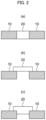
- the configuration in which the first resin component and the second resin component are fused together is not particularly limited.
- Examples of the configuration include a configuration in which the second resin component 20 plugs the inside of the through hole disposed at the first resin component 10, as shown in Fig. 2 (a) ; a configuration in which the second resin component 20 plugs an inlet of the through hole disposed at the first resin component 10, as shown in Fig. 2 (b) ; and a configuration in which the second resin component 20 plugs a portion of the inside and an inlet of the through hole disposed at the first resin component 10, as shown in Fig. 2 (c) .
- the method for fusing the first resin component with the second resin component is not particularly limited, and may be performed by a known process such as injection molding or laser fusing.
- the material for the first resin component and the second resin component is not particularly limited, and may be selected from the exemplary materials for the resin component as described above.
- the material for the first resin component may be the same or different from the material for the second resin component. From the viewpoint of ease of fusion, the material for the first resin component is preferably the same as the material for the second resin component.
- the safety valve structure may configure a portion of the metal-resin complex as described above.
- the first resin component and the second resin component may configure the resin component and the fragile portion of the metal-resin complex, respectively.
Applications Claiming Priority (2)
| Application Number | Priority Date | Filing Date | Title |
|---|---|---|---|
| JP2020103294 | 2020-06-15 | ||
| PCT/JP2021/021757 WO2021256328A1 (fr) | 2020-06-15 | 2021-06-08 | Complexe métal-résine, dispositif de refroidissement, procédé de fabrication de complexe métal-résine et structure de soupape de sécurité |
Publications (1)
| Publication Number | Publication Date |
|---|---|
| EP4167347A1 true EP4167347A1 (fr) | 2023-04-19 |
Family
ID=79267944
Family Applications (1)
| Application Number | Title | Priority Date | Filing Date |
|---|---|---|---|
| EP21825767.3A Withdrawn EP4167347A1 (fr) | 2020-06-15 | 2021-06-08 | Complexe métal-résine, dispositif de refroidissement, procédé de fabrication de complexe métal-résine et structure de soupape de sécurité |
Country Status (6)
| Country | Link |
|---|---|
| US (1) | US20230168050A1 (fr) |
| EP (1) | EP4167347A1 (fr) |
| JP (1) | JPWO2021256328A1 (fr) |
| KR (1) | KR20220143089A (fr) |
| CN (1) | CN115298504A (fr) |
| WO (1) | WO2021256328A1 (fr) |
Families Citing this family (1)
| Publication number | Priority date | Publication date | Assignee | Title |
|---|---|---|---|---|
| DE102017001683A1 (de) * | 2017-02-22 | 2018-08-23 | Carl Freudenberg Kg | Energiespeichersystem |
Family Cites Families (20)
| Publication number | Priority date | Publication date | Assignee | Title |
|---|---|---|---|---|
| US5325913A (en) * | 1993-06-25 | 1994-07-05 | The United States Of America As Represented By The Secretary Of The Navy | Module cooling system |
| US6085831A (en) * | 1999-03-03 | 2000-07-11 | International Business Machines Corporation | Direct chip-cooling through liquid vaporization heat exchange |
| US7841577B2 (en) | 2002-12-16 | 2010-11-30 | Corona International Corporation | Composite of aluminum material and synthetic resin molding and process for producing the same |
| JP4635483B2 (ja) * | 2003-09-29 | 2011-02-23 | 日産自動車株式会社 | 電池収納ケース、電池モジュール、および、組電池 |
| US8534348B2 (en) * | 2005-09-01 | 2013-09-17 | Molex Incorporated | Heat pipe and method for manufacturing same |
| JP4020957B2 (ja) | 2005-12-19 | 2007-12-12 | ヤマセ電気株式会社 | 異種材料との接合部を有する金属材料及びレーザーを用いてのその加工方法 |
| JP5058593B2 (ja) | 2006-12-28 | 2012-10-24 | Ykk株式会社 | 金属と樹脂の複合体の製造方法 |
| WO2009031632A1 (fr) | 2007-09-05 | 2009-03-12 | Taisei Plas Co., Ltd. | Procede de production de composite metal-resine |
| TW200912237A (en) * | 2007-09-13 | 2009-03-16 | Univ Tamkang | Thermal spreader with enhancement of support strength and capillarity |
| WO2010050011A1 (fr) * | 2008-10-29 | 2010-05-06 | 三菱重工業株式会社 | Système d'élément électrique |
| JP2010269534A (ja) * | 2009-05-22 | 2010-12-02 | Taisei Plas Co Ltd | 金属を含む接着複合体とその製造方法 |
| EP3425391A1 (fr) | 2011-11-04 | 2019-01-09 | inRegen | Tests de puissance et de criblage de médicaments |
| JP6021370B2 (ja) * | 2012-03-22 | 2016-11-09 | 株式会社東芝 | 電池および組電池 |
| JP2013197021A (ja) * | 2012-03-22 | 2013-09-30 | Toshiba Corp | 組電池および電池 |
| JP5967206B2 (ja) * | 2012-09-21 | 2016-08-10 | 株式会社村田製作所 | 電子機器 |
| IN2015DN00995A (fr) | 2013-07-18 | 2015-06-12 | Mitsui Chemicals Inc | |
| JP5704735B1 (ja) | 2014-04-27 | 2015-04-22 | 関東精密株式会社 | 水冷式プレート型冷却ユニット |
| JP6406892B2 (ja) * | 2014-06-20 | 2018-10-17 | 古河電気工業株式会社 | 冷却装置 |
| JPWO2016117711A1 (ja) * | 2015-01-23 | 2017-11-02 | 古河電気工業株式会社 | 金属部材と樹脂モールドとの複合体および樹脂モールドとの複合体形成用金属部材 |
| JP7111579B2 (ja) * | 2018-10-22 | 2022-08-02 | 帝人株式会社 | ポリカーボネート樹脂組成物およびそれからなる樹脂金属複合成形体 |
-
2021
- 2021-06-08 JP JP2022531703A patent/JPWO2021256328A1/ja not_active Ceased
- 2021-06-08 KR KR1020227032138A patent/KR20220143089A/ko active Search and Examination
- 2021-06-08 US US17/922,753 patent/US20230168050A1/en active Pending
- 2021-06-08 CN CN202180021109.1A patent/CN115298504A/zh active Pending
- 2021-06-08 EP EP21825767.3A patent/EP4167347A1/fr not_active Withdrawn
- 2021-06-08 WO PCT/JP2021/021757 patent/WO2021256328A1/fr unknown
Also Published As
| Publication number | Publication date |
|---|---|
| JPWO2021256328A1 (fr) | 2021-12-23 |
| CN115298504A (zh) | 2022-11-04 |
| US20230168050A1 (en) | 2023-06-01 |
| WO2021256328A1 (fr) | 2021-12-23 |
| KR20220143089A (ko) | 2022-10-24 |
Similar Documents
| Publication | Publication Date | Title |
|---|---|---|
| EP4167347A1 (fr) | Complexe métal-résine, dispositif de refroidissement, procédé de fabrication de complexe métal-résine et structure de soupape de sécurité | |
| EP2793312A1 (fr) | Borne, procédé de fabrication de borne, et structure de connexion câble-borne | |
| DE112011105871B4 (de) | Akkumulatorherstellungsverfahren und Akkumulator | |
| JP5056091B2 (ja) | アルミ電解コンデンサ及びアルミ電解コンデンサ用リード線の製造方法 | |
| WO2023030445A1 (fr) | Système de transmission d'énergie électrique pour véhicule, et appareil de charge et véhicule électrique | |
| US20220124943A1 (en) | Cooling device and method for manufacturing cooling device | |
| WO2006134665A1 (fr) | Élément doté d’un revêtement composé principalement d’étain, procédé de formation du revêtement et procédé de soudage | |
| WO2016011913A1 (fr) | Contact de commutateur à revêtement d'alliage métallique réfractaire et son procédé de préparation | |
| US9999148B2 (en) | Electronics housing and manufacturing method of electronics housing | |
| JP2012064880A (ja) | 樹脂封止金属部品、それに用いるリードフレーム、及び金属部品の製造方法 | |
| KR20190129326A (ko) | 벤팅 장치 및 그의 제조 방법 | |
| US9743531B2 (en) | Electronic apparatus and manufacturing method of electronic apparatus | |
| TWI787330B (zh) | 熱管及熱管的製造方法 | |
| JP2014164966A (ja) | 端子の製造方法、その製造方法に用いる端子材、その製造方法により製造された端子、電線の終端接続構造体およびその製造方法、ならびに、端子用の銅または銅合金板材 | |
| CN107621192A (zh) | 可钎焊金属板材料,以及具有由该材料制成的构件的热交换器 | |
| JP2021190665A (ja) | 冷却装置 | |
| JP7453846B2 (ja) | 金属樹脂接合体の製造方法及び金型 | |
| US20230417493A1 (en) | Temperature control unit and method for manufacturing temperature control unit | |
| WO2018221161A1 (fr) | Fil électrique, fil électrique doté de borne, faisceau, et procédé de fabrication de fil électrique | |
| KR102114839B1 (ko) | 전자파 차폐 및 방열 복합시트를 위한 코어-쉘 구조의 금속수산화물 제조방법 | |
| JP6820294B2 (ja) | 端子付き電線 | |
| CN100517806C (zh) | 防爆膜的制备方法 | |
| WO2023171729A1 (fr) | Unité de barre omnibus, moteur pour véhicule électrique et procédé de fabrication de barre omnibus | |
| JP2014195068A (ja) | 冷却器およびその製造方法 | |
| US11764547B2 (en) | Method for manufacturing surge absorbing device |
Legal Events
| Date | Code | Title | Description |
|---|---|---|---|
| STAA | Information on the status of an ep patent application or granted ep patent |
Free format text: STATUS: THE INTERNATIONAL PUBLICATION HAS BEEN MADE |
|
| PUAI | Public reference made under article 153(3) epc to a published international application that has entered the european phase |
Free format text: ORIGINAL CODE: 0009012 |
|
| STAA | Information on the status of an ep patent application or granted ep patent |
Free format text: STATUS: REQUEST FOR EXAMINATION WAS MADE |
|
| 17P | Request for examination filed |
Effective date: 20220916 |
|
| AK | Designated contracting states |
Kind code of ref document: A1 Designated state(s): AL AT BE BG CH CY CZ DE DK EE ES FI FR GB GR HR HU IE IS IT LI LT LU LV MC MK MT NL NO PL PT RO RS SE SI SK SM TR |
|
| RAP3 | Party data changed (applicant data changed or rights of an application transferred) |
Owner name: MITSUI CHEMICALS, INC. |
|
| DAV | Request for validation of the european patent (deleted) | ||
| DAX | Request for extension of the european patent (deleted) | ||
| STAA | Information on the status of an ep patent application or granted ep patent |
Free format text: STATUS: THE APPLICATION HAS BEEN WITHDRAWN |
|
| 18W | Application withdrawn |
Effective date: 20231228 |