EP4166929A1 - Wasserqualitätsanalysegerät und wasserqualitätsanalyseverfahren - Google Patents
Wasserqualitätsanalysegerät und wasserqualitätsanalyseverfahren Download PDFInfo
- Publication number
- EP4166929A1 EP4166929A1 EP21823112.4A EP21823112A EP4166929A1 EP 4166929 A1 EP4166929 A1 EP 4166929A1 EP 21823112 A EP21823112 A EP 21823112A EP 4166929 A1 EP4166929 A1 EP 4166929A1
- Authority
- EP
- European Patent Office
- Prior art keywords
- absorbance
- turbidity
- wavelength
- oxidation reaction
- correction
- Prior art date
- Legal status (The legal status is an assumption and is not a legal conclusion. Google has not performed a legal analysis and makes no representation as to the accuracy of the status listed.)
- Pending
Links
- XLYOFNOQVPJJNP-UHFFFAOYSA-N water Substances O XLYOFNOQVPJJNP-UHFFFAOYSA-N 0.000 title claims description 178
- 238000004458 analytical method Methods 0.000 title claims description 16
- 238000012937 correction Methods 0.000 claims abstract description 137
- 238000002835 absorbance Methods 0.000 claims abstract description 119
- 238000005259 measurement Methods 0.000 claims abstract description 119
- 238000007254 oxidation reaction Methods 0.000 claims abstract description 72
- 239000012086 standard solution Substances 0.000 claims abstract description 70
- 238000004364 calculation method Methods 0.000 claims abstract description 47
- 238000012545 processing Methods 0.000 claims abstract description 32
- 238000001514 detection method Methods 0.000 claims abstract description 27
- IJGRMHOSHXDMSA-UHFFFAOYSA-N Atomic nitrogen Chemical compound N#N IJGRMHOSHXDMSA-UHFFFAOYSA-N 0.000 claims description 56
- 229910052757 nitrogen Inorganic materials 0.000 claims description 28
- 229910052698 phosphorus Inorganic materials 0.000 claims description 20
- 239000011574 phosphorus Substances 0.000 claims description 20
- OAICVXFJPJFONN-UHFFFAOYSA-N Phosphorus Chemical compound [P] OAICVXFJPJFONN-UHFFFAOYSA-N 0.000 claims description 17
- 230000001590 oxidative effect Effects 0.000 claims description 17
- 239000007800 oxidant agent Substances 0.000 claims description 12
- 230000001678 irradiating effect Effects 0.000 claims description 8
- USHAGKDGDHPEEY-UHFFFAOYSA-L potassium persulfate Chemical compound [K+].[K+].[O-]S(=O)(=O)OOS([O-])(=O)=O USHAGKDGDHPEEY-UHFFFAOYSA-L 0.000 claims description 7
- 239000007788 liquid Substances 0.000 description 20
- 239000012895 dilution Substances 0.000 description 18
- 238000010790 dilution Methods 0.000 description 18
- MWUXSHHQAYIFBG-UHFFFAOYSA-N Nitric oxide Chemical compound O=[N] MWUXSHHQAYIFBG-UHFFFAOYSA-N 0.000 description 15
- 239000003153 chemical reaction reagent Substances 0.000 description 14
- 239000011259 mixed solution Substances 0.000 description 12
- 238000010521 absorption reaction Methods 0.000 description 10
- 230000003287 optical effect Effects 0.000 description 10
- 238000010586 diagram Methods 0.000 description 9
- 239000000243 solution Substances 0.000 description 8
- HEMHJVSKTPXQMS-UHFFFAOYSA-M Sodium hydroxide Chemical compound [OH-].[Na+] HEMHJVSKTPXQMS-UHFFFAOYSA-M 0.000 description 6
- VEXZGXHMUGYJMC-UHFFFAOYSA-N Hydrochloric acid Chemical compound Cl VEXZGXHMUGYJMC-UHFFFAOYSA-N 0.000 description 4
- 238000012886 linear function Methods 0.000 description 4
- 238000000034 method Methods 0.000 description 4
- 229910001392 phosphorus oxide Inorganic materials 0.000 description 4
- VSAISIQCTGDGPU-UHFFFAOYSA-N tetraphosphorus hexaoxide Chemical compound O1P(O2)OP3OP1OP2O3 VSAISIQCTGDGPU-UHFFFAOYSA-N 0.000 description 4
- 229910017464 nitrogen compound Inorganic materials 0.000 description 3
- 150000002830 nitrogen compounds Chemical class 0.000 description 3
- 239000002245 particle Substances 0.000 description 3
- -1 phosphorus compound Chemical class 0.000 description 3
- 238000003756 stirring Methods 0.000 description 3
- CIWBSHSKHKDKBQ-JLAZNSOCSA-N Ascorbic acid Chemical compound OC[C@H](O)[C@H]1OC(=O)C(O)=C1O CIWBSHSKHKDKBQ-JLAZNSOCSA-N 0.000 description 2
- YZCKVEUIGOORGS-OUBTZVSYSA-N Deuterium Chemical compound [2H] YZCKVEUIGOORGS-OUBTZVSYSA-N 0.000 description 2
- NHNBFGGVMKEFGY-UHFFFAOYSA-N Nitrate Chemical compound [O-][N+]([O-])=O NHNBFGGVMKEFGY-UHFFFAOYSA-N 0.000 description 2
- QAOWNCQODCNURD-UHFFFAOYSA-N Sulfuric acid Chemical compound OS(O)(=O)=O QAOWNCQODCNURD-UHFFFAOYSA-N 0.000 description 2
- 238000000354 decomposition reaction Methods 0.000 description 2
- 229910052805 deuterium Inorganic materials 0.000 description 2
- 238000002474 experimental method Methods 0.000 description 2
- NBIIXXVUZAFLBC-UHFFFAOYSA-K phosphate Chemical compound [O-]P([O-])([O-])=O NBIIXXVUZAFLBC-UHFFFAOYSA-K 0.000 description 2
- 229940085991 phosphate ion Drugs 0.000 description 2
- 238000007781 pre-processing Methods 0.000 description 2
- 239000002699 waste material Substances 0.000 description 2
- 229910052724 xenon Inorganic materials 0.000 description 2
- FHNFHKCVQCLJFQ-UHFFFAOYSA-N xenon atom Chemical compound [Xe] FHNFHKCVQCLJFQ-UHFFFAOYSA-N 0.000 description 2
- 239000005995 Aluminium silicate Substances 0.000 description 1
- QGZKDVFQNNGYKY-UHFFFAOYSA-O Ammonium Chemical compound [NH4+] QGZKDVFQNNGYKY-UHFFFAOYSA-O 0.000 description 1
- IOVCWXUNBOPUCH-UHFFFAOYSA-M Nitrite anion Chemical compound [O-]N=O IOVCWXUNBOPUCH-UHFFFAOYSA-M 0.000 description 1
- 230000002378 acidificating effect Effects 0.000 description 1
- 235000012211 aluminium silicate Nutrition 0.000 description 1
- 229960005070 ascorbic acid Drugs 0.000 description 1
- 235000010323 ascorbic acid Nutrition 0.000 description 1
- 239000011668 ascorbic acid Substances 0.000 description 1
- 238000004140 cleaning Methods 0.000 description 1
- 150000001875 compounds Chemical class 0.000 description 1
- 238000007865 diluting Methods 0.000 description 1
- 230000000694 effects Effects 0.000 description 1
- NLYAJNPCOHFWQQ-UHFFFAOYSA-N kaolin Chemical compound O.O.O=[Al]O[Si](=O)O[Si](=O)O[Al]=O NLYAJNPCOHFWQQ-UHFFFAOYSA-N 0.000 description 1
- QSHDDOUJBYECFT-UHFFFAOYSA-N mercury Chemical compound [Hg] QSHDDOUJBYECFT-UHFFFAOYSA-N 0.000 description 1
- 229910052753 mercury Inorganic materials 0.000 description 1
- VLAPMBHFAWRUQP-UHFFFAOYSA-L molybdic acid Chemical compound O[Mo](O)(=O)=O VLAPMBHFAWRUQP-UHFFFAOYSA-L 0.000 description 1
- 229940005654 nitrite ion Drugs 0.000 description 1
- 125000001477 organic nitrogen group Chemical group 0.000 description 1
- 150000003018 phosphorus compounds Chemical class 0.000 description 1
- 239000010865 sewage Substances 0.000 description 1
- WFKWXMTUELFFGS-UHFFFAOYSA-N tungsten Chemical compound [W] WFKWXMTUELFFGS-UHFFFAOYSA-N 0.000 description 1
- 229910052721 tungsten Inorganic materials 0.000 description 1
- 239000010937 tungsten Substances 0.000 description 1
- 239000002351 wastewater Substances 0.000 description 1
Images


Classifications
-
- G—PHYSICS
- G01—MEASURING; TESTING
- G01N—INVESTIGATING OR ANALYSING MATERIALS BY DETERMINING THEIR CHEMICAL OR PHYSICAL PROPERTIES
- G01N21/00—Investigating or analysing materials by the use of optical means, i.e. using sub-millimetre waves, infrared, visible or ultraviolet light
- G01N21/17—Systems in which incident light is modified in accordance with the properties of the material investigated
- G01N21/25—Colour; Spectral properties, i.e. comparison of effect of material on the light at two or more different wavelengths or wavelength bands
- G01N21/31—Investigating relative effect of material at wavelengths characteristic of specific elements or molecules, e.g. atomic absorption spectrometry
- G01N21/33—Investigating relative effect of material at wavelengths characteristic of specific elements or molecules, e.g. atomic absorption spectrometry using ultraviolet light
-
- G—PHYSICS
- G01—MEASURING; TESTING
- G01N—INVESTIGATING OR ANALYSING MATERIALS BY DETERMINING THEIR CHEMICAL OR PHYSICAL PROPERTIES
- G01N21/00—Investigating or analysing materials by the use of optical means, i.e. using sub-millimetre waves, infrared, visible or ultraviolet light
- G01N21/75—Systems in which material is subjected to a chemical reaction, the progress or the result of the reaction being investigated
- G01N21/77—Systems in which material is subjected to a chemical reaction, the progress or the result of the reaction being investigated by observing the effect on a chemical indicator
- G01N21/82—Systems in which material is subjected to a chemical reaction, the progress or the result of the reaction being investigated by observing the effect on a chemical indicator producing a precipitate or turbidity
-
- G—PHYSICS
- G01—MEASURING; TESTING
- G01N—INVESTIGATING OR ANALYSING MATERIALS BY DETERMINING THEIR CHEMICAL OR PHYSICAL PROPERTIES
- G01N31/00—Investigating or analysing non-biological materials by the use of the chemical methods specified in the subgroup; Apparatus specially adapted for such methods
- G01N31/005—Investigating or analysing non-biological materials by the use of the chemical methods specified in the subgroup; Apparatus specially adapted for such methods investigating the presence of an element by oxidation
-
- G—PHYSICS
- G01—MEASURING; TESTING
- G01N—INVESTIGATING OR ANALYSING MATERIALS BY DETERMINING THEIR CHEMICAL OR PHYSICAL PROPERTIES
- G01N33/00—Investigating or analysing materials by specific methods not covered by groups G01N1/00 - G01N31/00
- G01N33/18—Water
- G01N33/182—Water specific anions in water
-
- G—PHYSICS
- G01—MEASURING; TESTING
- G01N—INVESTIGATING OR ANALYSING MATERIALS BY DETERMINING THEIR CHEMICAL OR PHYSICAL PROPERTIES
- G01N21/00—Investigating or analysing materials by the use of optical means, i.e. using sub-millimetre waves, infrared, visible or ultraviolet light
- G01N21/17—Systems in which incident light is modified in accordance with the properties of the material investigated
- G01N21/25—Colour; Spectral properties, i.e. comparison of effect of material on the light at two or more different wavelengths or wavelength bands
- G01N21/27—Colour; Spectral properties, i.e. comparison of effect of material on the light at two or more different wavelengths or wavelength bands using photo-electric detection ; circuits for computing concentration
- G01N21/274—Calibration, base line adjustment, drift correction
-
- G—PHYSICS
- G01—MEASURING; TESTING
- G01N—INVESTIGATING OR ANALYSING MATERIALS BY DETERMINING THEIR CHEMICAL OR PHYSICAL PROPERTIES
- G01N2201/00—Features of devices classified in G01N21/00
- G01N2201/12—Circuits of general importance; Signal processing
- G01N2201/121—Correction signals
Definitions
- the present invention relates to a water quality analyzer and a water quality analysis method capable of measuring a total nitrogen concentration in sample water.
- a water quality analyzer such as a total nitrogen total phosphorus meter is provided with a reactor for oxidation reaction of a component in sample water.
- Sample water after oxidation reaction in the reactor is supplied to a measurement cell, and the sample water in the measurement cell is irradiated with measurement light from a light source.
- the measurement light having passed through the sample water in the measurement cell is detected by a detector, and the absorbance of a target component in the sample water is calculated based on detection intensity in the detector (see, for example, Patent Document 1 below).
- Patent Document 1 JP 2016-80441 A
- the form of the turbidity component may change. Specifically, it is considered that the absorbance depending on particle size also changes as particle size of a turbidity component changes with the oxidation reaction. In this case, if the correction coefficient is not changed according to a change amount of the particle size of the turbidity component, an error may occur in the corrected absorbance.
- a decomposition amount of an oxidant used in the oxidation reaction may be affected by a turbidity component.
- a turbidity component in a case where a turbidity component is contained in sample water, it is conceivable that the turbidity component inhibits decomposition of the oxidant, and a residual amount of the oxidant after the oxidation reaction increases. Since an oxidant such as potassium peroxodisulfate has absorption at a measurement wavelength, in a case where a residual amount of this type of oxidant increases, the absorbance at the measurement wavelength may increase.
- the present invention has been made in view of the above circumstances, and an object of the present invention is to provide a water quality analyzer and a water quality analysis method capable of appropriately correcting absorbance when measuring a total nitrogen concentration in sample water containing a turbidity component.
- a first aspect of the present invention is a water quality analyzer capable of measuring a total nitrogen concentration in sample water containing a turbidity component, the water quality analyzer including an oxidation reaction unit, a light source, a detector, an absorbance calculation unit, a correction calculation unit, a storage unit, a turbidity component detection processing unit, and a correction coefficient update processing unit.
- the oxidation reaction unit causes a component in the sample water to undergo an oxidation reaction.
- the light source irradiates the sample water after the oxidation reaction in the oxidation reaction unit with measurement light.
- the detector detects intensity at a plurality of wavelengths of measurement light having passed through the sample water.
- the absorbance calculation unit calculates absorbance at each wavelength based on intensity of a plurality of wavelengths detected by the detector.
- the correction calculation unit corrects absorbance by performing calculation using a correction formula based on the absorbance at each wavelength calculated by the absorbance calculation unit.
- the storage unit stores a correction coefficient included in the correction formula.
- the turbidity component detection processing unit supplies a turbidity standard solution to the oxidation reaction unit, and irradiates the turbidity standard solution after the oxidation reaction with measurement light from the light source, so as to cause the detector to detect intensity at a plurality of the wavelengths of the measurement light having passed through the turbidity standard solution.
- the correction coefficient update processing unit causes the absorbance calculation unit to calculate absorbance at each wavelength based on the intensity at a plurality of the wavelengths detected by the turbidity component detection processing unit, and updates the correction coefficient stored in the storage unit based on the calculated absorbance at each wavelength.
- a second aspect of the present invention is a water quality analysis method capable of measuring a total nitrogen concentration in sample water containing a turbidity component.
- the water quality analysis method includes the steps of oxidizing a component in the sample water, irradiating the sample water after the oxidation reaction with measurement light, detecting intensity at a plurality of wavelengths of measurement light having passed through the sample water, calculating absorbance at each wavelength based on the detected intensity at a plurality of the wavelengths, correcting absorbance by performing calculation using a correction formula based on the calculated absorbance at each wavelength, storing a correction coefficient included in the correction formula, causing a component in a turbidity standard solution to undergo an oxidation reaction, irradiating the turbidity standard solution after the oxidation reaction with measurement light, detecting intensity at a plurality of the wavelengths of measurement light that has passed through the turbidity standard solution, and calculating absorbance at each wavelength based on the detected intensity at a plurality of the wavelengths, and updating the stored correction
- a correction coefficient stored in the storage unit can be updated to an appropriate value based on detection intensity of measurement light having passed through the turbidity standard solution after an oxidation reaction, so that absorbance can be appropriately corrected when a total nitrogen concentration in the sample water containing a turbidity component is measured.
- FIG. 1 is a schematic diagram illustrating a configuration example of a water quality analyzer according to an embodiment of the present invention.
- the water quality analyzer according to the present embodiment is a total nitrogen total phosphorus meter capable of measuring a total nitrogen concentration (TN concentration) and a total phosphorus concentration (TP concentration) of sample water, and only a configuration related to a flow path of liquid such as sample water is illustrated in FIG. 1 .
- TN concentration total nitrogen concentration
- TP concentration total phosphorus concentration
- Sample water is sewage, river water, factory wastewater, or the like, and contains various components such as a nitrogen compound and a phosphorus compound.
- Anitrogen compound in the sample water is present as, for example, a nitrate ion, a nitrite ion, an ammonium ion, and organic nitrogen.
- a nitrogen oxide nitrate ion
- a nitrogen oxide is generated by oxidizing all nitrogen compounds in the sample water, and the concentration of the nitrogen oxides is measured.
- a phosphorus compound in the sample water is present as, for example, a phosphate ion, hydrolyzable phosphorus, and organic phosphorus.
- a phosphorus oxide phosphate ion
- a phosphorus oxide is generated by oxidizing all phosphorus compounds in the sample water, and the concentration of the phosphorus oxide is measured.
- the sample water contains a turbidity component in addition to a target component to be measured, such as a nitrogen oxide or a phosphorus oxide.
- the turbidity component is a component other than the target component, and is a component that generates turbidity in the sample water.
- the water quality analyzer includes, for example, a first multi-port valve 1, a second multi-port valve 2, a syringe 3, a reactor (reactor) 4, a measurement cell 5, a stirring pump 6, a discharge pump 7, a first switching valve 8, a second switching valve 9, and the like. These units are connected to each other via a pipe.
- the first multi-port valve 1 and the second multi-port valve 2 include, for example, an eight-port valve, and include one common port and eight ports (first to eighth ports) selectively communicable with the common port.
- ports of the first multi-port valve 1 and the second multi-port valve 2 are indicated by numbers "1" to "8" in association with the first to eighth ports, respectively.
- the common port of the first multi-port valve 1 is connected to the first port of the second multi-port valve 2.
- the common port of the second multi-port valve 2 is connected to the syringe 3.
- the syringe 3 is provided with, for example, a cylindrical body 31 and a plunger 32, and suction operation to the syringe 3 and discharge operation from the syringe 3 can be performed as the plunger 32 inserted into the cylindrical body 31 is displaced.
- a turbidity standard solution storage portion 10 storing a turbidity standard solution is connected to the first port of the first multi-port valve 1.
- the turbidity standard solution in the turbidity standard solution storage portion 10 may be stirred by a stirring device (not illustrated).
- a stirring device not illustrated.
- suction operation by the syringe 3 is performed in a state in which the first port of the first multi-port valve 1 communicates with the common port and the first port of the second multi-port valve 2 communicates with the common port, the turbidity standard solution can be supplied into the syringe 3.
- the turbidity standard solution is a solution containing a component to be a reference in determining turbidity.
- a kaolin solution can be exemplified, but the turbidity standard solution is not limited to this, and any other turbidity standard solution can be stored in the turbidity standard solution storage portion 10.
- Sample water is supplied online from a sample water supply source such as a drainage facility to the second port of the first multi-port valve 1 via piping. Therefore, when suction operation by the syringe 3 is performed in a state in which the second port of the first multi-port valve 1 communicates with the common port and the first port of the second multi-port valve 2 communicates with the common port, the sample water can be supplied into the syringe 3 online.
- a sample supplied online is supplied to the second port after predetermined preprocessing is performed by, for example, a preprocessing device (not illustrated).
- a preprocessing device not illustrated.
- the present invention is not limited to the online configuration, and sample water collected in advance and set in the water quality analyzer may be configured to be supplied offline.
- Reagent storage portions 21 to 26 in which different reagents are stored are connected to the second to seventh ports of the second multi-port valve 2. By causing any of these ports to communicate with the common port and performing suction operation by the syringe 3, a reagent can be supplied into the syringe 3 and mixed with sample water.
- the reagents stored in the reagent storage portions 21 to 26 include sulfuric acid, molybdic acid, ascorbic acid, sodium hydroxide, potassium peroxodisulfate, and hydrochloric acid, but are not limited to these, and any other reagent can be stored in the reagent storage portions 21 to 26.
- a dilution water storage portion 12 is connected to the sixth port of the first multi-port valve 1.
- Dilution water used for diluting sample water, cleaning the reactor 4 or the measurement cell 5, or the like is stored in the dilution water storage portion 12.
- the dilution water for example, pure water can be used.
- a mixed solution of sample water, a reagent, and dilution water can be generated in the syringe 3.
- the mixed solution in the syringe 3 is stirred by driving of the stirring pump 6.
- the reactor 4 is connected to the fourth port of the first multi-port valve 1, and when discharge operation by the syringe 3 is performed in a state where the fourth port communicates with the common port and the first port of the second multi-port valve 2 communicates with the common port, the mixed solution in the syringe 3 can be supplied to the reactor 4.
- liquid inside is irradiated with an ultraviolet ray from a light source 41.
- various components such as a nitrogen compound and a phosphorus compound in the sample water can be oxidized by irradiating the mixed solution with an ultraviolet ray from the light source 41. That is, the reactor 4 constitutes an oxidation reaction unit that causes a component in the sample water to undergo an oxidation reaction.
- the reagent in the mixed solution can function as an oxidant.
- the oxidant for example, potassium peroxodisulfate may be used.
- an oxidation reaction in the reactor 4 is not limited to the configuration in which the oxidation reaction is performed by irradiation with an ultraviolet ray, and the oxidation reaction may be performed in another mode such as control of pressure and temperature.
- the turbidity standard solution in the syringe 3 can also be supplied to the reactor 4.
- a reagent for example, potassium peroxodisulfate
- a reagent for example, potassium peroxodisulfate
- the turbidity standard solution may be brought into an alkaline atmosphere by suctioning of a reagent such as sodium hydroxide into the syringe 3.
- a reagent such as sodium hydroxide
- the turbidity standard solution is supplied to the reactor 4, the turbidity standard solution is irradiated with an ultraviolet ray from the light source 41.
- the light source 41 for example, a low-pressure mercury lamp can be used, but the light source 41 is not limited to this.
- Another type of the light source 41 such as an excimer laser, a deuterium lamp, a xenon lamp, or a Hg-Zn-Pb lamp may be used.
- Liquid in the reactor 4 is heated by, for example, a heater (not illustrated). At this time, the temperature of the liquid in the reactor 4 is controlled to be a preset temperature based on a detection signal from a temperature sensor (not illustrated) that detects the temperature of the liquid.
- Liquid after an oxidation reaction in the reactor 4 is supplied into the syringe 3 by suction operation by the syringe 3.
- the measurement cell 5 is connected to the seventh port of the first multi-port valve 1, and when discharge operation by the syringe 3 is performed in a state where the seventh port and the common port communicate with each other and the first port of the second multi-port valve 2 and the common port communicate with each other, the liquid after an oxidation reaction in the syringe 3 can be supplied to the measurement cell 5.
- Liquid (mixed solution or turbidity standard liquid) after an oxidation reaction in the measurement cell 5 is irradiated with measurement light from a light source 51.
- a light source 51 for example, a xenon lamp that emits white light can be used, but the light source 51 is not limited to this, and another type of the light source 51 such as a deuterium lamp or a tungsten lamp may be used.
- a reagent such as hydrochloric acid may be sucked into the syringe 3 to cause the liquid after an oxidation reaction to be in an acidic atmosphere, and then the liquid may be supplied to the measurement cell 5.
- Measurement light transmitted through the measurement cell 5 is detected by a detector 52 such as a photodiode.
- a detector 52 such as a photodiode.
- the measurement light passing through the mixed solution is detected by the detector 52 so that the total nitrogen concentration or the total phosphorus concentration in sample water can be measured based on a detection signal of the detection.
- the liquid in the measurement cell 5 is heated by, for example, a heater (not illustrated). At this time, the temperature of the liquid in the measurement cell 5 is controlled to be a preset temperature based on a detection signal from a temperature sensor (not illustrated) that detects the temperature of the liquid.
- dilution water can also be individually flown into the reactor 4 and the measurement cell 5. That is, the inside of the reactor 4 can be cleaned by individually sucking dilution water into the syringe 3 and allowing the dilution water to flow into the reactor 4 from the syringe 3. Further, the inside of the measurement cell 5 can be cleaned by individually sucking dilution water into the syringe 3 and allowing the dilution water to flow from the syringe 3 into the measurement cell 5.
- a span solution storage portion 11 is connected to the third port of the first multi-port valve 1.
- the span solution storage portion 11 stores a span solution used when span calibration is performed.
- the span solution can be supplied from the span solution storage portion 11 into the syringe 3.
- the seventh port of the first multi-port valve 1 and the common port are made to communicate with each other, and discharge operation by the syringe 3 is performed, so that the span solution can be supplied into the measurement cell 5 to perform span calibration.
- Two standard sample storage portions 13 and 14 are connected to the eighth port of the first multi-port valve 1 via the first switching valve 8.
- a standard sample is stored in each of the standard sample storage portions 13 and 14, a standard sample for measuring the total nitrogen concentration is stored in the standard sample storage portion 13 on the one hand, and a standard sample for measuring the total phosphorus concentration is stored in the standard sample storage portion 14 on the other.
- the first switching valve 8 can selectively allow one of two of the standard sample storage portions 13 and 14 to communicate with the eighth port by switching a flow path.
- a standard sample can be supplied from one of two of the standard sample storage portions 13 and 14 into the syringe 3. After the above, the standard sample can be supplied into the measurement cell 5 by causing the seventh port of the first multi-port valve 1 and the common port to communicate with each other and performing discharge operation by the syringe 3.
- the liquid in the measurement cell 5 is discharged to the outside of the device. Further, the liquid in the reactor 4 is also discharged to the outside of the device by driving of the discharge pump 7.
- the fifth port of the first multi-port valve 1 communicates with a waste liquid destination and a drain destination via the second switching valve 9.
- the second switching valve 9 can selectively guide the liquid in the device to either the waste liquid destination or the drain destination by switching a flow path.
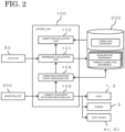
- FIG. 2 is a block diagram illustrating an electrical configuration of the water quality analyzer of FIG. 1 .
- Operation of the water quality analyzer is controlled by a control unit 100 including, for example, a central processing unit (CPU).
- a control unit 100 including, for example, a central processing unit (CPU).
- CPU central processing unit
- a storage unit 200, an operation unit 300, and the like are electrically connected to the control unit 100.
- the control unit 100 When the CPU executes a program, the control unit 100 functions as an absorbance calculation unit 101, a correction calculation unit 102, a turbidity component detection processing unit 103, a correction coefficient update processing unit 104, and the like.
- the storage unit 200 includes, for example, a random access memory (RAM), a read only memory (ROM), or a hard disk, and stores data necessary for operation of the water quality analyzer.
- the operation unit 300 includes, for example, a touch panel, a keyboard, or a mouse, and is operated by the user.
- the absorbance calculation unit 101 calculates the absorbance based on a detection signal from the detector 52.
- a half mirror, an optical filter (none of which are illustrated), and the like are provided between the light source 51 and the detector 52.
- Measurement light (white light) emitted from the light source 51 is divided into a plurality of rays of light by the half mirror before or after passing through the measurement cell 5, and each ray of light enters the detector 52 after passing through different optical filters.
- Each optical filter transmits only light of a specific wavelength.
- an optical filter that transmits a measurement wavelength for example, 220 nm
- an optical filter that transmits a turbidity correction wavelength for example, 275 nm
- the measurement light emitted from the light source 51 is divided into two rays of light by the half mirror and passes through different optical filters, so that light of each of the measurement wavelength and the turbidity correction wavelength is incident on the detector 52.
- the detector 52 can detect the intensity at two wavelengths (measurement wavelength and turbidity correction wavelength) of the measurement light having passed through sample water in the measurement cell 5.
- the measurement light is divided into three or more rays of light by providing a plurality of half mirrors, and these rays of light pass through three or more optical filters and enter the detector 52. That is, the detector 52 only needs to be able to detect intensities at a plurality of wavelengths.
- the absorbance calculation unit 101 calculates absorbance at each wavelength based on intensity of a plurality of (for example, two) wavelengths detected by the detector 52.
- the measurement wavelength is a wavelength corresponding to the total nitrogen in sample water, and nitrogen oxide (target component) in the sample water has absorption at the measurement wavelength.
- the turbidity correction wavelength is a wavelength corresponding to a turbidity component in sample water, and a turbidity component in the sample water has absorption at the measurement wavelength and the turbidity correction wavelength.
- the turbidity correction wavelength is longer than the measurement wavelength.
- the absorbance at each wavelength calculated by the absorbance calculation unit 101 is stored in the storage unit 200.
- the absorbance at the measurement wavelength is stored in the storage unit 200 as measurement absorbance.
- the absorbance at the turbidity correction wavelength is stored in the storage unit 200 as turbidity correction absorbance.
- the correction calculation unit 102 performs calculation using Correction formulas (1) and (2) below based on the absorbance at each wavelength (measurement wavelength and turbidity correction wavelength) to correct the absorbance.
- A is the absorbance after correction.
- B is the absorbance at the measurement wavelength (measurement absorbance).
- C is the absorbance at the turbidity correction wavelength (turbidity correction absorbance) corrected and converted into the absorbance corresponding to the measurement wavelength.
- D is the absorbance at the turbidity correction wavelength (turbidity correction absorbance).
- k is a proportional term of the correction coefficient.
- m is a constant term of the correction coefficient.
- the correction calculation unit 102 can remove the influence of absorption by a turbidity component and accurately calculate the absorbance of a target component by performing calculation of substituting the measurement absorbance B and the turbidity correction absorbance D as variables into Correction formulas (1) and (2).
- the correction coefficients k and m are stored in the storage unit 200.
- a series of operation for updating the correction coefficients k and m stored in the storage unit 200 can be performed so that the correction coefficients k and m can be updated to appropriate values.
- the turbidity component detection processing unit 103 supplies the turbidity standard solution from the turbidity standard solution storage portion 10 to the reactor 4, irradiates the turbidity standard solution with an ultraviolet ray from the light source 41 to perform an oxidation reaction on the turbidity standard solution, supplies the turbidity standard solution after the oxidation reaction to the measurement cell 5, and irradiates the turbidity standard solution with measurement light from the light source 51.
- intensity at the measurement wavelength and the turbidity correction wavelength of the measurement light having passed through the turbidity standard solution after the oxidation reaction is detected by the detector 52.
- the turbidity correction calibration As described above, in the turbidity correction calibration, operation of the first multi-port valve 1, the second multi-port valve 2, the syringe 3, the light sources 41 and 51, and the like are appropriately controlled by the turbidity component detection processing unit 103.
- the turbidity correction calibration is started based on, for example, operation of the operation unit 300 by the user.
- an operation screen may be displayed on a display unit (not illustrated), and the user may perform input on the operation screen by operating the operation unit 300.
- the correction coefficient update processing unit 104 causes the absorbance calculation unit 101 to calculate the measurement absorbance and the turbidity correction absorbance based on intensity at the measurement wavelength and the turbidity correction wavelength detected by the turbidity component detection processing unit 103. Then, the correction coefficient update processing unit 104 updates the correction coefficients k and m stored in the storage unit 200 based on the calculated measurement absorbance and turbidity correction absorbance.
- FIG. 3 is a diagram for describing a specific mode of the turbidity correction calibration.
- a case in which a plurality of sets of absorbance data are acquired with the measurement absorbance and the turbidity correction absorbance calculated by one time of measurement using the turbidity standard solution as one set of absorbance data, and then the correction coefficients k and m are updated based on the absorbance data will be described.
- one time of measurement using the turbidity standard solution means operation of detecting the measurement absorbance and the turbidity correction absorbance based on intensity at the measurement wavelength and the turbidity correction wavelength obtained by supplying the turbidity standard solution to the reactor 4 and irradiating the turbidity standard solution after an oxidation reaction with measurement light from the light source 51.
- a plurality of sets of absorbance data are acquired by performing measurement using each turbidity standard solution once or a plurality of times using a plurality of types of the turbidity standard solution having different concentrations.
- the turbidity standard solution having different concentrations can be generated by supplying dilution water in the dilution water storage portion 12 into the syringe 3 to dilute the turbidity standard solution.
- a plurality of sets of acquired absorbance data are plotted on a graph in which the vertical axis represents the measurement absorbance (220 nm) and the horizontal axis represents the turbidity correction absorbance (275 nm).
- the measurement absorbance plotted on the graph may be a value obtained by subtracting the absorbance at a zero point (zero absorbance) obtained by zero calibration from the measurement absorbance calculated by measurement using the turbidity standard solution.
- the correction coefficient update processing unit 104 updates the correction coefficients k and m by overwriting the correction coefficients k and m stored in the storage unit 200 with the correction coefficients k and m newly obtained.
- other calculation may be performed in addition to the calculation using the least squares method or instead of the calculation using the least squares method. In this case, the calculation may be performed such that the value of the constant term m becomes "0".
- a plurality of times of measurement may be performed using one kind of the turbidity standard solution, or only one time of measurement may be performed. In a case where measurement is performed only once, a straight line connecting a point of an obtained set of absorbance data and the origin may be obtained as a linear function.
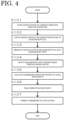
- FIG. 4 is a flowchart showing an example of a water quality analysis method using the water quality analyzer of FIG. 1 .
- the sample water (mixed solution) is supplied to the reactor 4 to cause a component in the sample water to undergo an oxidation reaction in the reactor 4 (step S101).
- the sample water after the oxidation reaction is supplied to the measurement cell 5 (step S102), and the sample water in the measurement cell 5 is irradiated with measurement light from the light source 51 (step S103).
- the measurement light having passed through the sample water is detected by the detector 52 (step S104).
- the detector 52 detects intensity of a plurality of (for example, two) wavelengths.
- the absorbance calculation unit 101 calculates the absorbance at each wavelength based on the intensity at each wavelength (step S105).
- the correction calculation unit 102 reads the correction coefficient from the storage unit 200 (step S 106), and performs calculation using Correction formulas (1) and (2) based on the calculated absorbance at each wavelength, so that the absorbance is corrected (step S107).
- the correction coefficient included in Correction formulas (1) and (2) are stored in the storage unit 200 in advance.
- FIG. 5 is a flowchart showing an example of the turbidity correction calibration.
- the turbidity standard solution is supplied to the reactor 4 to cause a component in the turbidity standard solution to undergo an oxidation reaction in the reactor 4 (step S201).
- the turbidity standard solution after the oxidation reaction is supplied to the measurement cell 5 (step S202), and the turbidity standard solution in the measurement cell 5 is irradiated with measurement light from the light source 51 (step S203).
- the measurement light that has passed through the turbidity standard solution is detected by the detector 52 (step S204).
- the detector 52 detects intensity of a plurality of (for example, two) wavelengths.
- the absorbance calculation unit 101 calculates the absorbance at each wavelength based on the intensity at each wavelength (step S205).
- the correction coefficient update processing unit 104 updates the correction coefficient stored in the storage unit 200 based on the calculated absorbance at each wavelength (step S206).
- the configuration may be such that at least one of the steps illustrated in FIGS. 4 and 5 is manually performed by an operator.
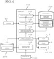
- FIG. 6 is a block diagram illustrating a variation of the water quality analyzer.
- the configuration in which the turbidity correction calibration is started based on operation of the operation unit 300 by the user is described.
- the turbidity correction calibration is automatically started according to a preset schedule.
- the similar configurations are denoted by the same reference numerals in the diagram, and detailed description of them is omitted.
- control unit 100 functions as a schedule setting processing unit 105 when the CPU executes a program.
- the schedule setting processing unit 105 sets the start date and time of the turbidity correction calibration as a schedule on the basis of operation of the operation unit 300 by the user, and stores the set schedule in the storage unit 200.
- an operation screen for the user to set the schedule may be displayed on a display unit (not illustrated).
- the turbidity component detection processing unit 103 automatically starts supply of the turbidity standard solution to the reactor 4 based on the schedule stored in the storage unit 200, so as to execute the turbidity correction calibration at a frequency corresponding to the schedule.
- the schedule of the turbidity correction calibration is not limited to the configuration in which the user operates the operation unit 300, and may be automatically set based on operation time of the water quality analyzer or the like.
- the turbidity correction wavelength may be a wavelength corresponding to the total phosphorus in sample water.
- the "wavelength corresponding to the total phosphorus in sample water” is a wavelength at which phosphorus oxide (target component) in the sample water has absorption, and is, for example, 880 nm.
- an optical filter that transmits the measurement wavelength for example, 880 nm
- the water quality analyzer is a total nitrogen total phosphorus meter
- the present invention is also applicable to a total nitrogen meter. That is, the present invention can be applied to a total nitrogen meter that can measure the total nitrogen concentration but cannot measure the total phosphorus concentration.
- the water quality analyzer is not limited to the configuration including two of the multi-port valves 1 and 2, and may have a configuration including only one multi-port valve or a configuration including three or more multi-port valves. Further, the type and number of valves, pipes, and the like are optional, and are not limited to those in the configuration as in the above embodiment. For example, it is also possible to employ a configuration in which the reactor 4 also functions as the measurement cell 5.
- a water quality analyzer is a water quality analyzer capable of measuring a total nitrogen concentration in sample water containing a turbidity component.
- the water quality analyzer may include:
- a correction coefficient stored in the storage unit can be updated to an appropriate value based on detection intensity of measurement light having passed through the turbidity standard solution after an oxidation reaction, so that absorbance can be appropriately corrected when a total nitrogen concentration in the sample water containing a turbidity component is measured.
- the plurality of the wavelengths may include a measurement wavelength corresponding to total nitrogen in the sample water and a turbidity correction wavelength longer than the measurement wavelength.
- intensity at two wavelengths of the measurement wavelength corresponding to the total nitrogen in the sample water and the turbidity correction wavelength longer than the measurement wavelength is detected by the detector, and a correction coefficient stored in the storage unit can be updated to an appropriate value based on the detected intensity.
- the correction coefficient may include a proportional term multiplied by absorbance at the turbidity correction wavelength.
- the absorbance at the turbidity correction wavelength can be updated to an appropriate value, the absorbance can be appropriately corrected when the total nitrogen concentration in the sample water containing a turbidity component is measured.
- the turbidity correction wavelength may be a wavelength corresponding to total phosphorus in the sample water.
- the measurement wavelength at the time of measuring the total phosphorus concentration can be used as the turbidity correction wavelength.
- the turbidity component detection processing unit may automatically start supply of a turbidity standard solution to the oxidation reaction unit.
- supply of the turbidity standard solution to the oxidation reaction unit can be automatically started, and the correction coefficient stored in the storage unit can be automatically updated.
- the oxidation reaction unit may perform an oxidation reaction using potassium peroxodisulfate as an oxidant.
- the absorbance can be appropriately corrected in the water quality analyzer capable of measurement using potassium peroxodisulfate as an oxidant.
- a component in the sample water may undergo an oxidation reaction as the sample water is irradiated with an ultraviolet ray.
- the absorbance can be appropriately corrected in the water quality analyzer capable of performing measurement using ultraviolet absorptiometry or the like.
- a water quality analysis method is a water quality analysis method capable of measuring a total nitrogen concentration in sample water containing a turbidity component.
- the water quality analysis method includes the steps of
- a correction coefficient included in the correction coefficient can be updated to an appropriate value based on detection intensity of measurement light having passed through the turbidity standard solution after the oxidation reaction, so that absorbance can be appropriately corrected when a total nitrogen concentration in the sample water containing a turbidity component is measured.
Applications Claiming Priority (2)
| Application Number | Priority Date | Filing Date | Title |
|---|---|---|---|
| JP2020102236 | 2020-06-12 | ||
| PCT/JP2021/005250 WO2021250944A1 (ja) | 2020-06-12 | 2021-02-12 | 水質分析計及び水質分析方法 |
Publications (1)
| Publication Number | Publication Date |
|---|---|
| EP4166929A1 true EP4166929A1 (de) | 2023-04-19 |
Family
ID=78847173
Family Applications (1)
| Application Number | Title | Priority Date | Filing Date |
|---|---|---|---|
| EP21823112.4A Pending EP4166929A1 (de) | 2020-06-12 | 2021-02-12 | Wasserqualitätsanalysegerät und wasserqualitätsanalyseverfahren |
Country Status (4)
| Country | Link |
|---|---|
| EP (1) | EP4166929A1 (de) |
| JP (1) | JPWO2021250944A1 (de) |
| CN (1) | CN115917294A (de) |
| WO (1) | WO2021250944A1 (de) |
Families Citing this family (1)
| Publication number | Priority date | Publication date | Assignee | Title |
|---|---|---|---|---|
| CN117517231B (zh) * | 2024-01-03 | 2024-04-12 | 杭州泽天春来科技股份有限公司 | 总氮水质在线分析仪的分析方法、系统及可读介质 |
Family Cites Families (8)
| Publication number | Priority date | Publication date | Assignee | Title |
|---|---|---|---|---|
| JPS64461A (en) * | 1987-03-09 | 1989-01-05 | Minoru Tada | Instrument for measuring nitrogen compound in water |
| JPH0797079B2 (ja) * | 1989-01-28 | 1995-10-18 | 株式会社堀場製作所 | Uv法による全窒素測定方法 |
| US5420432A (en) * | 1991-03-19 | 1995-05-30 | Welsh Water Enterprises Limited | Organic pollutant monitor |
| SE509036C2 (sv) * | 1993-06-29 | 1998-11-30 | Foss Tecator Ab | Förfarande för mätning av kemiska och fysikaliska parametrar för att karakterisera och klassificera vattensuspensioner |
| JP4044399B2 (ja) * | 2002-09-03 | 2008-02-06 | 東亜ディーケーケー株式会社 | 全窒素・全りん測定装置および試料水導入装置 |
| TW200930814A (en) * | 2007-10-18 | 2009-07-16 | Unilever Nv | Method for producing a foaming agent |
| US9588050B2 (en) * | 2012-02-17 | 2017-03-07 | Shimadzu Corporation | Total nitrogen measurement apparatus |
| JP6394263B2 (ja) | 2014-10-14 | 2018-09-26 | 株式会社島津製作所 | 水質分析計 |
-
2021
- 2021-02-12 CN CN202180041580.7A patent/CN115917294A/zh active Pending
- 2021-02-12 EP EP21823112.4A patent/EP4166929A1/de active Pending
- 2021-02-12 WO PCT/JP2021/005250 patent/WO2021250944A1/ja unknown
- 2021-02-12 JP JP2022530024A patent/JPWO2021250944A1/ja active Pending
Also Published As
| Publication number | Publication date |
|---|---|
| CN115917294A (zh) | 2023-04-04 |
| JPWO2021250944A1 (de) | 2021-12-16 |
| WO2021250944A1 (ja) | 2021-12-16 |
Similar Documents
| Publication | Publication Date | Title |
|---|---|---|
| US11703494B2 (en) | Measuring device | |
| EP4166929A1 (de) | Wasserqualitätsanalysegerät und wasserqualitätsanalyseverfahren | |
| CN107533043B (zh) | 水质分析装置 | |
| US10317385B2 (en) | Calibration method for water hardness measurement | |
| JP6965502B2 (ja) | 水質分析計 | |
| JP6665751B2 (ja) | 水質分析計 | |
| US10627384B1 (en) | Water quality analyzer | |
| US10345321B2 (en) | Automatic analyzer and method | |
| JP6730579B2 (ja) | 分析装置 | |
| JP4259402B2 (ja) | 全リン測定装置 | |
| US9513227B2 (en) | Method for quantitative determination of oxidant and apparatus for quantitative determination of oxidant | |
| JP2004279339A (ja) | 濃度測定装置 | |
| WO2020152896A1 (ja) | 水質分析計及び水質分析方法 | |
| WO2004011928A1 (ja) | 水中微量成分の測定方法及び装置 | |
| EP3635369B1 (de) | Kolorimetrischer analysator mit verbesserter fehlererkennung | |
| JP2004184132A (ja) | 水質分析装置 | |
| JP2004257916A (ja) | 全リン測定方法及び装置 | |
| US10677717B2 (en) | Colorimetric analyzer with reagent diagnostics | |
| JP2001124757A (ja) | 3態窒素分析システムにおけるシステムの自己診断方法 | |
| US20220136961A1 (en) | Method for calibrating a photometric analyzer | |
| Niculescu et al. | Accuracy Improvement for the Biochemistry Assays by Using Total Dissolved Solids and Turbidimetry Measurements | |
| JP2011117747A (ja) | シリカ濃度測定装置及びシリカ濃度測定方法 | |
| KR20200102318A (ko) | 물 샘플 분석 기기 | |
| CN112304880A (zh) | 测试、验证、校准或调整自动分析设备的方法 | |
| CN111344573A (zh) | 水质分析仪 |
Legal Events
| Date | Code | Title | Description |
|---|---|---|---|
| STAA | Information on the status of an ep patent application or granted ep patent |
Free format text: STATUS: THE INTERNATIONAL PUBLICATION HAS BEEN MADE |
|
| PUAI | Public reference made under article 153(3) epc to a published international application that has entered the european phase |
Free format text: ORIGINAL CODE: 0009012 |
|
| STAA | Information on the status of an ep patent application or granted ep patent |
Free format text: STATUS: REQUEST FOR EXAMINATION WAS MADE |
|
| 17P | Request for examination filed |
Effective date: 20221222 |
|
| AK | Designated contracting states |
Kind code of ref document: A1 Designated state(s): AL AT BE BG CH CY CZ DE DK EE ES FI FR GB GR HR HU IE IS IT LI LT LU LV MC MK MT NL NO PL PT RO RS SE SI SK SM TR |
|
| DAV | Request for validation of the european patent (deleted) | ||
| DAX | Request for extension of the european patent (deleted) |