EP4160218B1 - Automatisches analysegerät - Google Patents
Automatisches analysegerät Download PDFInfo
- Publication number
- EP4160218B1 EP4160218B1 EP21817738.4A EP21817738A EP4160218B1 EP 4160218 B1 EP4160218 B1 EP 4160218B1 EP 21817738 A EP21817738 A EP 21817738A EP 4160218 B1 EP4160218 B1 EP 4160218B1
- Authority
- EP
- European Patent Office
- Prior art keywords
- probe
- reagent
- specimen
- liquid
- vessel
- Prior art date
- Legal status (The legal status is an assumption and is not a legal conclusion. Google has not performed a legal analysis and makes no representation as to the accuracy of the status listed.)
- Active
Links
Images


Classifications
-
- G—PHYSICS
- G01—MEASURING; TESTING
- G01N—INVESTIGATING OR ANALYSING MATERIALS BY DETERMINING THEIR CHEMICAL OR PHYSICAL PROPERTIES
- G01N35/00—Automatic analysis not limited to methods or materials provided for in any single one of groups G01N1/00 - G01N33/00; Handling materials therefor
- G01N35/10—Devices for transferring samples or any liquids to, in, or from, the analysis apparatus, e.g. suction devices, injection devices
- G01N35/1009—Characterised by arrangements for controlling the aspiration or dispense of liquids
- G01N35/1011—Control of the position or alignment of the transfer device
-
- G—PHYSICS
- G01—MEASURING; TESTING
- G01N—INVESTIGATING OR ANALYSING MATERIALS BY DETERMINING THEIR CHEMICAL OR PHYSICAL PROPERTIES
- G01N35/00—Automatic analysis not limited to methods or materials provided for in any single one of groups G01N1/00 - G01N33/00; Handling materials therefor
- G01N35/10—Devices for transferring samples or any liquids to, in, or from, the analysis apparatus, e.g. suction devices, injection devices
- G01N35/1002—Reagent dispensers
-
- G—PHYSICS
- G01—MEASURING; TESTING
- G01N—INVESTIGATING OR ANALYSING MATERIALS BY DETERMINING THEIR CHEMICAL OR PHYSICAL PROPERTIES
- G01N35/00—Automatic analysis not limited to methods or materials provided for in any single one of groups G01N1/00 - G01N33/00; Handling materials therefor
- G01N35/10—Devices for transferring samples or any liquids to, in, or from, the analysis apparatus, e.g. suction devices, injection devices
- G01N35/1009—Characterised by arrangements for controlling the aspiration or dispense of liquids
- G01N2035/1025—Fluid level sensing
-
- G—PHYSICS
- G01—MEASURING; TESTING
- G01N—INVESTIGATING OR ANALYSING MATERIALS BY DETERMINING THEIR CHEMICAL OR PHYSICAL PROPERTIES
- G01N35/00—Automatic analysis not limited to methods or materials provided for in any single one of groups G01N1/00 - G01N33/00; Handling materials therefor
- G01N35/10—Devices for transferring samples or any liquids to, in, or from, the analysis apparatus, e.g. suction devices, injection devices
- G01N2035/1027—General features of the devices
- G01N2035/1048—General features of the devices using the transfer device for another function
- G01N2035/1058—General features of the devices using the transfer device for another function for mixing
Definitions
- the present invention relates to an automatic analyzer according to claim 1.
- Examples of an automatic analyzer that analyzes components of blood, urine, spinal fluid, and the like of a patient include (a) a biochemical automatic analyzer that measures an amount of transmitted light or scattered light obtained by irradiating a reaction liquid of a specimen and a reagent with light, and (b) an immune automatic analyzer in which a reagent added with a label reacts with a specimen and an amount of light emitted from the label is measured.
- a technique for preventing liquid scattering when a liquid is discharged from a probe to a reaction vessel is disclosed in these automatic analyzers (see PTL 1).
- US 4586546 A discloses an automatic analyzer from which the pre-characterising part of claim 1 starts out.
- a probe discharges a liquid while the probe is immersed in a liquid of several millimeters.
- a liquid level above a tip end of the probe and a liquid flow around the tip end of the probe are poor, and it is not clear whether the liquid can be stirred efficiently by a discharge operation.
- an automatic analyzer as set forth in the appended claims.
- the automatic analyzer after a probe starts to discharge a specimen to a vessel, the probe is lifted while discharging the specimen or a reagent and, as a height of a liquid level of a liquid in the vessel is raised, a distance between the liquid level in the vessel and a tip end of the probe is gradually increased, wherein the liquid in the vessel is the total discharge amount of the specimen and the reagent.
- stirring is efficiently performed by a discharge operation.
- FIG. 1 is a block diagram schematically illustrating an overall configuration of an automatic analyzer 10 according to a first embodiment.
- the automatic analyzer 10 mainly includes an analysis unit 1 that analyzes a mixed liquid of a liquid specimen and a reagent, a computer 3 (a control unit) that controls the analysis unit 1, and an analysis control unit 8.
- the analysis control unit 8 controls an operation of each mechanism of the analysis unit 1. Details will be described later.
- the computer 3 is connected to the analysis control unit 8, an A/D converter 7, and the like via an interface 9.
- the computer 3 sends a command to the analysis control unit 8 or the like and controls an operation of each mechanism.
- A/D-converted data (a photometric value) acquired from the analysis unit 1 is sent to the computer 3.
- the computer 3 executes calculation processing using the acquired data (the photometric value). That is, the computer 3 can control each mechanism of the analysis unit 1 via the analysis control unit 8, and can perform data calculation processing.
- the interface 9 is connected to a printer 4 for printing, a memory 6 that is a recording device, a keyboard 2 for inputting an operation command and the like, and a display device 5 implemented by a CRT display, a liquid crystal display or the like.
- the memory 6 includes, for example, a hard disk memory or an external memory.
- the memory 6 records information such as an analysis parameter, an analysis item request, a calibration result, and an analysis result.
- FIG. 2 is a plan view schematically illustrating a configuration of the analysis unit 1.
- the analysis unit 1 mainly includes sample racks 25, a reagent disk 21, and a reaction disk (an incubator) 15.
- the sample rack 25 holds a specimen vessel 24.
- the reagent disk 21 holds a reagent vessel 22.
- the reaction disk 15 holds a reaction vessel 14 on its circumference.
- the analysis unit 1 further includes a dispensing mechanism 11, a dispensing mechanism washing unit 26, a reaction vessel washing unit 27, a light source 12, and a spectroscopic detector 13.
- the sample rack 25 is movable in a horizontal direction, and a plurality of the specimen vessels 24 for holding biological samples (hereinafter referred to as specimens) such as blood are placed on the sample rack 25.
- the reagent disk 21 can intermittently rotate clockwise and counterclockwise, and a plurality of the reagent vessels 22 corresponding to analysis items of the automatic analyzer 10 are placed on the reagent disk 21.
- FIG. 2 the reagent disk 21 is illustrated in a manner of being partially cut away.
- the reagent disk 21 has a circular shape in a plan view.
- two reagent vessels 22 are arranged in a radial direction of the reagent disk 21 (two reference numerals 22 at two ends are illustrated). That is, two circular rows of the reagent vessels 22 arranged in a manner of surrounding the center of the reagent disk 21 are concentrically disposed in the reagent disk 21.
- Reagents in the two reagent vessels 22 arranged in the radial direction may be reagents of different types.
- the reaction disk 15 can intermittently rotate clockwise and counterclockwise, and a plurality of the reaction vessels 14 in which a specimen and a reagent reacts with each other are placed on a circumference of the reaction disk 15.
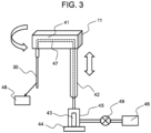
- the dispensing mechanism 11 aspirates a specimen from the specimen vessel 24 placed on the sample rack 25, aspirates a reagent from the reagent vessel 22 in the reagent disk 21, and discharges and dispenses an aspirated liquid into the reaction vessel 14 in the reaction disk 15.
- the dispensing mechanism 11 does not only indicate a tip end portion of a vessel constituting a flow path for aspirating and discharging a liquid, but also indicates a vessel around the entire flow path from a pump (for example, a syringe) for aspirating and discharging a liquid to the tip end portion.
- FIG. 2 illustrates a vertical rotation operation unit (a movement unit) of the dispensing mechanism 11.
- the vertical rotation operation unit is an operation unit that changes a position where a liquid is aspirated and discharged.
- the light source 12 is disposed in the vicinity of an outer periphery of the reaction disk 15, and emits light to the reaction vessel 14.
- the spectroscopic detector 13 is disposed at an opposite side to the light source 12 with the reaction vessel 14 interposed between the spectroscopic detector 13 and the light source 12, and optically measures light absorbance of light emitted from the light source 12 to a specimen, a reagent, or a mixed liquid of a specimen and a reagent in a reaction vessel.
- the light source 12 emits light to each of the plurality of reaction vessels 14 that are moved accompanying with a rotational movement of the reaction disk 15.
- the spectroscopic detector 13 detects light transmitted through a specimen, a reagent, or a mixed liquid of a specimen and a reagent stored in each of the reaction vessels 14 for each wavelength of a test item.
- An analog signal such as an intensity of light detected by the spectroscopic detector 13 is input to the A/D converter 7 (see FIG. 1 ).
- the A/D converter 7 generates standard data or test data based on an input digital signal, and the generated data are sent to the computer 3.
- the analysis unit 1 may include a stirring mechanism that stirs a liquid in a reaction vessel.
- the stirring mechanism include a method in which a spatula is immersed in a solution in the reaction vessel 14 and the spatula is rotated to physically stir the solution, and a method in which ultrasonic waves are radiated to the solution to generate a swirling flow.
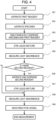
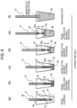
- the analysis control unit 8 controls the dispensing probe 30 to perform the discharge operation and the lifting operation until discharging of a liquid at a specified amount is completed (until P3).
- the analysis control unit 8 controls a lifting speed of the dispensing probe 30 so that the distance Da between the tip end of the dispensing probe 30 and the liquid level of the reaction liquid 36 in the reaction vessel 14 increases with an elapsed time until discharging of a liquid at a specified amount is completed (until P3).
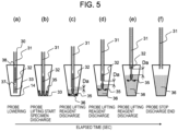
- a height position 35 (see FIG. 5 ) at which the discharged liquid arrives in the reaction liquid 36 also gradually changes by increasing the distance Da between the tip end of the dispensing probe 30 and the height of the liquid level of the reaction liquid 36 with an elapsed time.
- a liquid flow can be given to the entire reaction liquid 36, and an effect of efficiently stirring the discharged specimen 33 and reagent 32 by the discharge operation is obtained.
- a position at which the dispensing probe 30 is lowered into the reaction vessel 14 before the start of discharging is preferably in the vicinity of the bottom of the reaction vessel 14, that is, about several millimeters from the bottom of the reaction vessel 14.
- the analysis control unit 8 controls the dispensing probe 30 to be lowered to the vicinity of the bottom of the reaction vessel 14 and controls the start of the discharge operation, so that an influence of scattering can be reduced, and an effect of improving analysis performance is obtained.
- the automatic analyzer 10 When the specimen 33 and the reagent 32 that are different liquids are simultaneously discharged, the automatic analyzer 10 according to the first embodiment gradually changes an arrival position of a height of the discharged liquid in the reaction liquid 36 by increasing the distance Da between the tip end of the dispensing probe 30 and the liquid level of the reaction liquid 36 with an elapsed time. As a result, a large liquid flow is given to the entire reaction liquid, and the specimen 33 and the reagent 32 are efficiently stirred at the time of discharging.
- a time required for a subsequent additional stirring operation pipette stirring or the like
- processing capacity is improved.
- an additional stirring mechanism (stirring using ultrasonic waves or the like) is not necessary, which leads to space saving of a device.
- the dispensing probe 30 is lowered to the vicinity of a bottom portion of the reaction vessel 14 to start discharging, so that a position to which a scattered liquid adheres due to the segmented air 38 between the specimen 33 and the reagent 32 can be restricted to the vicinity of the bottom portion of the reaction vessel 14.
- the lifting operation of the probe is started at the same time as or several milliseconds after the start of discharging, so that the reagent 32 is discharged from a high position while the dispensing probe 30 is raised, and thus the scattered liquid adhering to the reaction vessel 14 is buried in the reaction liquid 36 due to the rise of the liquid level of the reaction liquid 36.
- an influence of scattering on measurement data can be reduced, and analysis performance can be improved.
- the automatic analyzer 10 may have a configuration of an automatic analyzer and a dispensing flow as will be described below.
- the dispensing probe 30 aspirates the specimen 33 from the specimen vessel 24 and discharges the specimen 33 to the reaction vessel 14. Subsequently, the tip end of the dispensing probe 30 is washed by the dispensing mechanism washing unit 26, and then the dispensing probe 30 aspirates the reagent 32 from the reagent vessel 22. Then, after the tip end of the dispensing probe 30 is washed by the dispensing mechanism washing unit 26, the analysis control unit 8 lowers the dispensing probe 30 to the vicinity of a height of a liquid level (for example, 1 mm above the liquid level) of the specimen 33 in the reaction vessel 14.
- a liquid level for example, 1 mm above the liquid level
- the analysis control unit 8 controls the dispensing probe 30 to start the lifting operation at the same time as the start of the discharge operation of the reagent 32 or after several milliseconds. Subsequently, the analysis control unit 8 controls the dispensing probe 30 to perform the lifting operation and the discharge operation until the reagent 32 is discharged at a specified amount. In addition, the analysis control unit 8 controls the lifting speed of the dispensing probe 30 so that the distance Da between the tip end of the dispensing probe 30 and the liquid level of the reaction liquid 36 in the reaction vessel 14 increases with an elapsed time. As a result, an arrival position of a height of a discharged liquid in the reaction liquid 36 is gradually changed. A large liquid flow is given to the entire reaction liquid, and the specimen 33 and the reagent 32 are efficiently stirred at the time of discharging.
- the automatic analyzer 10 may have a configuration of an automatic analyzer and a dispensing flow as will be described below.
- the automatic analyzer 10 includes two dispensing probes 30. That is, the automatic analyzer 10 includes a specimen probe that dispenses the specimen 33 and a reagent probe that dispenses the reagent 32.
- the specimen probe aspirates the specimen 33 from the specimen vessel 24.
- the reagent probe aspirates the reagent 32 from the reagent vessel 22.
- the analysis control unit 8 After tip ends of the two probes are washed by the dispensing mechanism washing unit 26, the analysis control unit 8 lowers the specimen probe and the reagent probe to the vicinity of the bottom of the reaction vessel 14, and starts to discharge the specimen 33 from the specimen probe and discharge the reagent 32 from the reagent probe.
- the analysis control unit 8 controls the dispensing probe 30 to start the lifting operation at the same time as the start of discharging or after several milliseconds. Subsequently, the analysis control unit 8 controls the dispensing probe 30 to perform the lifting operation and the discharge operation until the reagent 32 is discharged at a specified amount.
- the analysis control unit 8 controls the lifting speed of the dispensing probe 30 so that the distance Da between the tip end of the dispensing probe 30 and the liquid level of the reaction liquid 36 in the reaction vessel 14 increases with an elapsed time. As a result, an arrival position of a height of a discharged liquid in the reaction liquid 36 is gradually changed. A large liquid flow is given to the entire reaction liquid, and the specimen 33 and the reagent 32 are efficiently stirred at the time of discharging.
- the automatic analyzer 10 may have a configuration of an automatic analyzer and a dispensing flow as will be described below.
- the second reagent may be discharged into the reaction vessel 14 in step S06.
- the analysis control unit 8 lowers the dispensing probe 30 to the vicinity of a height of a liquid level (for example, 1 mm above the liquid level) of a reaction liquid (a mixed liquid of the specimen 33 and the reagent 32) in the reaction vessel 14. Thereafter, the analysis control unit 8 controls the dispensing probe 30 to start the lifting operation at the same time as the start of the discharge operation of the second reagent or after several milliseconds.
- the analysis control unit 8 controls the dispensing probe 30 to perform the lifting operation and the discharge operation until the second reagent is discharged at a specified amount.
- the analysis control unit 8 controls the lifting speed of the dispensing probe 30 so that the distance Da between the tip end of the dispensing probe 30 and the liquid level of the reaction liquid 36 in the reaction vessel 14 increases with an elapsed time. As a result, an arrival position of a height of a discharged liquid in the reaction liquid 36 is gradually changed. A large liquid flow is given to the entire reaction liquid, and the reaction liquid (the mixed liquid of the specimen 33 and the reagent 32) and the second reagent are efficiently stirred at the time of discharging.
- the analysis control unit 8 controls the lifting speed of the dispensing probe 30 so that the distance Da between the tip end of the dispensing probe 30 and the liquid level of the reaction liquid 36 in the reaction vessel 14 increases with an elapsed time until discharging of the reagent of a specified amount is completed in step S03.
- a procedure for lifting the dispensing probe 30 is not limited thereto.
- the analysis control unit 8 performs control for a predetermined time so that the distance Da increases with an elapsed time
- the analysis control unit 8 performs control so that the distance Da decreases with an elapsed time.
- the same effects as those of the first embodiment are also obtained. Since the configuration of the automatic analyzer 10 is the same as that in the first embodiment, differences in the dispensing operation will be mainly described below.
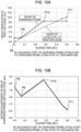
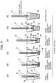
- FIG. 7 is a diagram schematically illustrating a movement of the dispensing probe 30 and its effect when the automatic analyzer 10 simultaneously dispenses the specimen and the first reagent in the second embodiment.
- a time change of a position of the tip end of the dispensing probe 30 in FIG. 7 will be described with reference to FIGS. 8A and 8B .
- FIG. 8A illustrates a relationship between the height of the tip end of the dispensing probe 30 from the bottom of the reaction vessel 14 and the height of the liquid level of the reaction liquid 36.
- FIG. 8B illustrates an elapsed time change in the distance Da between the tip end of the dispensing probe 30 and the liquid level of the reaction liquid 36.
- the second embodiment will be described in detail with reference to FIGS. 8A and 8B .
- Lifting control of the dispensing probe 30 performed by the analysis control unit 8 is the same as that in the first embodiment, and thus description thereof will be omitted.
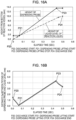
- FIG. 10A illustrates a relationship between the height of the tip end of the dispensing probe 30 from the bottom of the reaction vessel 14 and the height of the liquid level of the reaction liquid 36.
- FIG. 10B illustrates an elapsed time change in the distance Da between the tip end of the dispensing probe 30 and the liquid level of the reaction liquid 36.
- the third embodiment will be described in detail with reference to FIGS. 10A and 10B .
- Lifting control of the dispensing probe 30 performed by the analysis control unit 8 is the same as that in the first embodiment, and thus description thereof will be omitted.
- the automatic analyzer 10 can accurately determine whether the tip end of the dispensing probe 30 is immersed in the liquid level of the reaction liquid 36 by the liquid level detector 48 detecting the liquid level at the end of discharging.
- the analysis control unit 8 may add a data alarm indicating that the liquid level cannot be detected on the display device 5 via the interface 9.
- a user can know a cause of data failure, and can appropriately deal with the data failure, for example, by requesting a re-inspection. Appropriate measurement data can be obtained by performing a re-inspection, which leads to an improvement in reliability of a measurement result.
- the analysis control unit 8 may perform control to stop the tip end of the dispensing probe 30 above the liquid level of the reaction liquid 36 when discharging of the reagent of a specified amount is completed (when discharging of the reagent 32 is completed).
- a fourth embodiment a specific example will be described. In this case, the same effects as those of the first embodiment are obtained. Since the configuration of the automatic analyzer 10 is the same as that in the first embodiment, differences in a dispensing operation will be mainly described below.
- FIG. 12A illustrates a relationship between the height of the tip end of the dispensing probe 30 from the bottom of the reaction vessel 14 and the height of the liquid level of the reaction liquid 36.
- FIG. 12B illustrates an elapsed time change in the distance Da between the tip end of the dispensing probe 30 and the liquid level of the reaction liquid 36.
- the fourth embodiment will be described in detail with reference to FIGS. 12A and 12B .
- Lifting control of the dispensing probe 30 performed by the analysis control unit 8 is the same as that in the first embodiment, and thus description thereof will be omitted.
- the analysis control unit 8 controls the dispensing probe 30 to start the discharge operation (P12), and controls the probe lifting operation of the dispensing probe 30 so that the distance Da increases with an elapsed time (P13 to P14). After a certain period of time is elapsed, the analysis control unit 8 stops the lifting operation of the dispensing probe 30 at the point P14 of the elapsed time (at a time point before discharging of the reagent of a specified amount is completed). At this time, the analysis control unit 8 stops the lifting operation of the dispensing probe 30 so that the stopping position of the dispensing probe 30 is located at a position higher than the liquid level of the reaction liquid 36 after the reagent is discharged at a specified amount.
- the discharge operation is ended at a point P15 of the elapsed time. That is, at the point P15 of the elapsed time when discharging of the reagent of a specified amount is completed, the tip end of the dispensing probe 30 is located at a position higher than the liquid level of the reaction liquid 36.
- the analysis control unit 8 controls the tip end of the dispensing probe 30 to be higher than the liquid level of the reaction liquid 36 at the end of discharging.
- a state in the dispensing probe 30 before the start of the pipette stirring is a state in which the dispensing probe 30 is filled with a liquid (system water or the like).
- the analysis control unit 8 controls a lowering amount of the dispensing probe 30 to the reaction vessel 14 before the start of the discharge so as to immerse the tip end of the dispensing probe 30 in the discharged specimen 33 and the reaction liquid 36 (the specimen 33 and the reagent 32) for a certain period of time after discharging of the specimen 33 is completed, and after the tip end of the dispensing probe 30 is immersed, the analysis control unit 8 performs control to lift the dispensing probe 30 while discharging the reagent 32.
- the analysis control unit 8 may perform control such that the tip end of the dispensing probe 30 is in standby at a discharge start position until the tip end of the dispensing probe 30 is immersed in the discharged specimen 33 or the reaction liquid 36 (the specimen 33 and the reagent 32) for a certain period of time after discharging of the specimen 33 is completed, and thereafter perform control to lift the dispensing probe 30 while discharging the reagent 32.
- the immersing amount of the tip end of the dispensing probe 30 is about several millimeters in order to reduce a contamination range of a nozzle tip end.
- the analysis control unit 8 controls the dispensing probe 30 such that the immersing amount of the tip end of the dispensing probe 30 is about 4 mm or less.
- the tip end of the dispensing probe 30 is immersed in the specimen 33 or the liquid level of the reaction liquid 36 (the specimen 33 and the reagent 32) in the vessel for a certain period of time after the start or after the end of discharging the specimen 33. Accordingly, for example, when the tip end of the probe is immersed in a liquid when all specimens are discharged, the segmented air 37 that is present between the specimen 33 and the reagent 32 and is subsequently discharged from the tip end of the dispensing probe 30 is discharged into the specimen 33 or into the reaction liquid 36 of the specimen 33 and the reagent 32. In this case, since the tip end of the dispensing probe 30 is in the liquid, it is possible to prevent an influence of liquid scattering caused by the segmented air 37. That is, analysis performance can be improved.
Landscapes
- Physics & Mathematics (AREA)
- Health & Medical Sciences (AREA)
- Life Sciences & Earth Sciences (AREA)
- Chemical & Material Sciences (AREA)
- Analytical Chemistry (AREA)
- Biochemistry (AREA)
- General Health & Medical Sciences (AREA)
- General Physics & Mathematics (AREA)
- Immunology (AREA)
- Pathology (AREA)
- Automatic Analysis And Handling Materials Therefor (AREA)
Claims (13)
- Automatische Analysevorrichtung, umfassend:eine Sonde (30);einen Bewegungsmechanismus, der dazu eingerichtet ist, die Sonde zu bewegen; undeine Steuereinheit (3, 8), die dazu eingerichtet ist, den Bewegungsmechanismus zu steuern,wobei die Sonde (30) dazu eingerichtet ist, die Probe (33) und das Reagenz (32) anzusaugen und sie in das Gefäß (14) abzugeben, wobei die Sonde dazu eingerichtet ist, die Probe in einem Zustand anzusaugen, in dem das Reagenz in der Sonde vorhanden ist, undgekennzeichnet dadurch, dassdie Steuereinheit (3, 8) dazu eingerichtet ist, den Bewegungsmechanismus so zu steuern, dass, nachdem die Sonde (30) beginnt, die Probe (33) in das Gefäß (14) abzugeben, die Sonde angehoben wird, während sie die Probe oder das Reagenz (32) abgibt, und, während eine Höhe eines Flüssigkeitsspiegels einer Flüssigkeit im Gefäß ansteigt, ein Abstand (Da) zwischen dem Flüssigkeitsspiegel im Gefäß und einem Spitzenende der Sonde allmählich vergrößert wird, wobei die Flüssigkeit in dem Gefäß die gesamte Abgabemenge der Probe und des Reagenz ist.
- Automatische Analysevorrichtung nach Anspruch 1, dazu eingerichtet, dass:
bevor die Sonde (30) die Probe (33) in das Gefäß (14) abgibt, die Sonde die Probe in einem Zustand, in dem das Reagenz (32) angesaugt wird und das Reagenz in der Sonde vorhanden ist, ansaugt. - Automatische Analysevorrichtung nach Anspruch 2, dazu eingerichtet, dass:die Sonde (30) die Probe (33) in das Gefäß (14) abgibt, nachdem das Spitzenende der Sonde unter einen Einlass des Gefäßes bewegt worden ist, unddie Steuereinheit (3, 8) die Sonde nicht in einer vertikalen Richtung bewegt, während die Sonde die Probe in den Behälter abgibt.
- Automatische Analysevorrichtung nach Anspruch 1, dazu eingerichtet, dass:
die Steuereinheit (3, 8) den Bewegungsmechanismus so steuert, dass der Abstand zwischen dem Flüssigkeitsspiegel im Gefäß (14) und dem Spitzenende der Sonde (30) allmählich vergrößert und dann allmählich verkleinert wird, zumindest in einem Teil eines Zeitraums von dem Zeitpunkt, zu dem das Anheben der Sonde beginnt, während die Probe (33) oder das Reagenz (32) abgegeben wird, bis zu dem Zeitpunkt, zu dem die Sonde die Abgabe des Reagenz beendet. - Automatische Analysevorrichtung nach Anspruch 4, dazu eingerichtet, dass:
die Steuereinheit (3, 8) eine Position der Sonde (30) in einer Höhenrichtung so fixiert, dass der Abstand zwischen dem Flüssigkeitsspiegel in dem Gefäß (14) und dem Spitzenende der Sonde zumindest in einem Teil des Zeitraums von dem Zeitpunkt, zu dem das Anheben der Sonde beginnt, während die Probe (33) oder das Reagenz (32) abgegeben wird, bis zu dem Zeitpunkt, zu dem die Sonde die Abgabe des Reagenz beendet, allmählich verringert wird. - Automatische Analysevorrichtung nach Anspruch 4, dazu eingerichtet, dass:
die Steuereinheit (3, 8) den Bewegungsmechanismus so steuert, dass das Spitzenende der Sonde (30) in die Flüssigkeit im Gefäß (14) eingetaucht wird, wenn die Sonde die Abgabe des Reagenz (32) beendet. - Automatische Analysevorrichtung nach Anspruch 6 umfasst ferner:
einen Flüssigkeitsspiegel-Detektor (48), der dazu eingerichtet ist, eine Höhe eines Flüssigkeitsstands im Gefäß (14) zu detektieren, wobei der automatische Analysator dazu eingerichtet ist, dass:wenn die Sonde (30) die Abgabe des Reagens (32) beendet, die Steuereinheit (3, 8) bestimmt, ob die Spitze der Sonde in die Flüssigkeit im Gefäß eingetaucht ist oder nicht, entsprechend einem Detektionsergebnis durch den Flüssigkeitsspiegel-Detektor, undwenn die Sonde die Abgabe des Reagenz beendet hat, die Steuereinheit in dem Fall, dass das Spitzenende der Sonde nicht in die Flüssigkeit im Gefäß eingetaucht ist, einen Alarm für den oben genannten Fall ausgibt. - Automatische Analysevorrichtung nach Anspruch 4, dazu eingerichtet, dass:die Steuereinheit (3, 8) den Bewegungsmechanismus so steuert, dass die Spitze der Sonde (30) an einer festen Position oberhalb des Flüssigkeitsspiegels im Behälter (14) anhält, unddie Sonde die Abgabe des Reagenz (32) an der festen Position beendet.
- Automatische Analysevorrichtung nach Anspruch 2, dazu eingerichtet, dass:
die Steuereinheit (3, 8) den Bewegungsmechanismus so steuert, dass das Spitzenende der Sonde (30) zumindest in einem Teil eines Zeitraums von dem Zeitpunkt an, zu die Sonde die Abgabe der Probe (33) beginnt, bis zu dem Zeitpunkt, zu dem die Sonde angehoben zu werden beginnt, eingetaucht wird. - Automatische Analysevorrichtung nach Anspruch 9, dazu eingerichtet, dass:die Sonde (30) segmentierte Luft (37) zwischen dem Reagenz (32) und der Probe (33) ansaugt, unddie Sonde die segmentierte Luft in die Flüssigkeit im Behälter (14) abgibt, indem sie die Abgabe der Probe beendet, während das Spitzenende der Sonde in die Flüssigkeit im Gefäß eingetaucht wird.
- Automatische Analysevorrichtung nach Anspruch 2, dazu eingerichtet, dass:
bevor die Sonde (30) mit der Abgabe der Probe (33) beginnt, die Steuereinheit (3, 8) das Spitzenende der Sonde auf eine Höhe innerhalb von 1 mm über dem Flüssigkeitsspiegel im Behälter (14) absenkt, wenn die Sonde die Abgabe der gesamten Probe beendet. - Automatische Analysevorrichtung nach Anspruch 1, ferner umfassend:
eine Speichereinheit (6), die dazu eingerichtet ist, Daten zu speichern, die Flüssigkeitseigenschaften der Probe (33) oder Flüssigkeitseigenschaften des Reagenz (32) beschreiben, wobei die automatische Analysevorrichtung dazu eingerichtet ist, dass:
die Steuereinheit (3, 8) eine Hebegeschwindigkeit der Sonde (30) gemäß den in den Daten beschriebenen Flüssigkeitseigenschaften steuert. - Automatische Analysevorrichtung nach Anspruch 12, wobei
die Flüssigkeitseigenschaften Viskosität und/oder Kontaktwinkel enthalten.
Applications Claiming Priority (2)
| Application Number | Priority Date | Filing Date | Title |
|---|---|---|---|
| JP2020095585 | 2020-06-01 | ||
| PCT/JP2021/004769 WO2021245989A1 (ja) | 2020-06-01 | 2021-02-09 | 自動分析装置 |
Publications (3)
| Publication Number | Publication Date |
|---|---|
| EP4160218A1 EP4160218A1 (de) | 2023-04-05 |
| EP4160218A4 EP4160218A4 (de) | 2024-05-15 |
| EP4160218B1 true EP4160218B1 (de) | 2025-07-09 |
Family
ID=78830388
Family Applications (1)
| Application Number | Title | Priority Date | Filing Date |
|---|---|---|---|
| EP21817738.4A Active EP4160218B1 (de) | 2020-06-01 | 2021-02-09 | Automatisches analysegerät |
Country Status (5)
| Country | Link |
|---|---|
| US (1) | US12405285B2 (de) |
| EP (1) | EP4160218B1 (de) |
| JP (1) | JP7305891B2 (de) |
| CN (1) | CN115667940A (de) |
| WO (1) | WO2021245989A1 (de) |
Families Citing this family (5)
| Publication number | Priority date | Publication date | Assignee | Title |
|---|---|---|---|---|
| US20220268796A1 (en) * | 2021-02-19 | 2022-08-25 | Roche Molecular Systems, Inc. | Method of Operating a Laboratory Instrument |
| JP7779206B2 (ja) * | 2022-06-22 | 2025-12-03 | 横河電機株式会社 | 分注装置、分注方法及び分注プログラム |
| CN116338220A (zh) * | 2023-03-24 | 2023-06-27 | 深圳市科曼医疗设备有限公司 | 一种体外诊断仪器采样针混匀样本液的方法及应用 |
| JPWO2024219094A1 (de) * | 2023-04-20 | 2024-10-24 | ||
| JPWO2025004922A1 (de) * | 2023-06-30 | 2025-01-02 |
Family Cites Families (14)
| Publication number | Priority date | Publication date | Assignee | Title |
|---|---|---|---|---|
| US4586546A (en) * | 1984-10-23 | 1986-05-06 | Cetus Corporation | Liquid handling device and method |
| JPH06324058A (ja) * | 1993-05-11 | 1994-11-25 | Olympus Optical Co Ltd | 分注装置 |
| JP2002340915A (ja) * | 2001-05-21 | 2002-11-27 | Aloka Co Ltd | 分注装置及び分注方法 |
| JP4203469B2 (ja) * | 2004-12-24 | 2009-01-07 | アロカ株式会社 | 液体試料の攪拌装置 |
| JP2007078470A (ja) * | 2005-09-13 | 2007-03-29 | Hitachi Koki Co Ltd | 自動分注装置 |
| JP2010071766A (ja) * | 2008-09-17 | 2010-04-02 | Olympus Corp | 分注装置、自動分析装置および分注不良確認方法 |
| JP2010096643A (ja) * | 2008-10-17 | 2010-04-30 | Hitachi High-Technologies Corp | 分注装置、及びそれを用いた検体処理装置,自動分析装置 |
| JP5883214B2 (ja) * | 2010-05-25 | 2016-03-09 | 株式会社東芝 | 自動分析装置 |
| JP6381917B2 (ja) | 2014-01-23 | 2018-08-29 | キヤノンメディカルシステムズ株式会社 | 自動分析装置および試薬分注方法 |
| CN106471374B (zh) * | 2014-07-18 | 2018-12-14 | 株式会社日立高新技术 | 液体搅拌方法 |
| WO2016136377A1 (ja) | 2015-02-25 | 2016-09-01 | 株式会社 日立ハイテクノロジーズ | 自動分析装置 |
| WO2017134746A1 (ja) | 2016-02-02 | 2017-08-10 | コニカミノルタ株式会社 | 送液方法、ならびにこれを行う検出システムおよび検出装置 |
| JP7269869B2 (ja) * | 2019-12-05 | 2023-05-09 | 株式会社日立ハイテク | 自動分析装置及び分注方法 |
| JP7292195B2 (ja) * | 2019-12-06 | 2023-06-16 | 株式会社日立ハイテク | 自動分析装置 |
-
2021
- 2021-02-09 US US17/925,462 patent/US12405285B2/en active Active
- 2021-02-09 WO PCT/JP2021/004769 patent/WO2021245989A1/ja not_active Ceased
- 2021-02-09 EP EP21817738.4A patent/EP4160218B1/de active Active
- 2021-02-09 CN CN202180037328.9A patent/CN115667940A/zh active Pending
- 2021-02-09 JP JP2022528428A patent/JP7305891B2/ja active Active
Also Published As
| Publication number | Publication date |
|---|---|
| US12405285B2 (en) | 2025-09-02 |
| US20230184803A1 (en) | 2023-06-15 |
| JPWO2021245989A1 (de) | 2021-12-09 |
| WO2021245989A1 (ja) | 2021-12-09 |
| EP4160218A4 (de) | 2024-05-15 |
| EP4160218A1 (de) | 2023-04-05 |
| CN115667940A (zh) | 2023-01-31 |
| JP7305891B2 (ja) | 2023-07-10 |
Similar Documents
| Publication | Publication Date | Title |
|---|---|---|
| EP4160218B1 (de) | Automatisches analysegerät | |
| JP4117181B2 (ja) | 自動分析装置 | |
| EP2293083A1 (de) | Automatisches analysegerät | |
| JP5686744B2 (ja) | 自動分析装置 | |
| EP4071484B1 (de) | Automatisierter analysator | |
| EP2019321A1 (de) | Reinigungseinrichtung und analyseautomat | |
| JP7494375B2 (ja) | 自動分析装置、および自動分析装置における検体の吸引方法 | |
| JP2010236967A (ja) | 自動分析装置 | |
| JP4812352B2 (ja) | 自動分析装置及びその分注方法 | |
| JP5583337B2 (ja) | 自動分析装置及びその分注方法 | |
| JP4045211B2 (ja) | 自動分析装置 | |
| WO2021215068A1 (ja) | 分注装置、自動分析装置、分注方法 | |
| JP7499881B2 (ja) | 自動分析装置 | |
| JP4871025B2 (ja) | 自動分析装置およびその検体分注方法 | |
| JP2008145334A (ja) | 自動分析装置及びその試薬容器を移動する方法 | |
| JP2015137975A (ja) | 自動分析装置および試薬分注方法 | |
| JP5506189B2 (ja) | 自動分析装置 | |
| US20210318344A1 (en) | Test method and dispensing device | |
| JP7720410B2 (ja) | 自動分析装置 | |
| WO2024219094A1 (ja) | 自動分析装置及び自動分析方法 | |
| US10634690B2 (en) | Automatic analyzing apparatus | |
| CN120769989A (zh) | 自动分析装置以及其异常判定方法 | |
| JP2016040535A (ja) | 自動分析装置および自動分析装置の制御方法 |
Legal Events
| Date | Code | Title | Description |
|---|---|---|---|
| STAA | Information on the status of an ep patent application or granted ep patent |
Free format text: STATUS: THE INTERNATIONAL PUBLICATION HAS BEEN MADE |
|
| PUAI | Public reference made under article 153(3) epc to a published international application that has entered the european phase |
Free format text: ORIGINAL CODE: 0009012 |
|
| STAA | Information on the status of an ep patent application or granted ep patent |
Free format text: STATUS: REQUEST FOR EXAMINATION WAS MADE |
|
| 17P | Request for examination filed |
Effective date: 20221123 |
|
| AK | Designated contracting states |
Kind code of ref document: A1 Designated state(s): AL AT BE BG CH CY CZ DE DK EE ES FI FR GB GR HR HU IE IS IT LI LT LU LV MC MK MT NL NO PL PT RO RS SE SI SK SM TR |
|
| DAV | Request for validation of the european patent (deleted) | ||
| DAX | Request for extension of the european patent (deleted) | ||
| A4 | Supplementary search report drawn up and despatched |
Effective date: 20240412 |
|
| RIC1 | Information provided on ipc code assigned before grant |
Ipc: G01N 35/10 20060101ALI20240408BHEP Ipc: G01N 35/02 20060101AFI20240408BHEP |
|
| GRAP | Despatch of communication of intention to grant a patent |
Free format text: ORIGINAL CODE: EPIDOSNIGR1 |
|
| STAA | Information on the status of an ep patent application or granted ep patent |
Free format text: STATUS: GRANT OF PATENT IS INTENDED |
|
| INTG | Intention to grant announced |
Effective date: 20250404 |
|
| GRAS | Grant fee paid |
Free format text: ORIGINAL CODE: EPIDOSNIGR3 |
|
| GRAA | (expected) grant |
Free format text: ORIGINAL CODE: 0009210 |
|
| STAA | Information on the status of an ep patent application or granted ep patent |
Free format text: STATUS: THE PATENT HAS BEEN GRANTED |
|
| AK | Designated contracting states |
Kind code of ref document: B1 Designated state(s): AL AT BE BG CH CY CZ DE DK EE ES FI FR GB GR HR HU IE IS IT LI LT LU LV MC MK MT NL NO PL PT RO RS SE SI SK SM TR |
|
| REG | Reference to a national code |
Ref country code: GB Ref legal event code: FG4D |
|
| REG | Reference to a national code |
Ref country code: CH Ref legal event code: EP |
|
| REG | Reference to a national code |
Ref country code: IE Ref legal event code: FG4D |
|
| REG | Reference to a national code |
Ref country code: DE Ref legal event code: R096 Ref document number: 602021033909 Country of ref document: DE |
|
| REG | Reference to a national code |
Ref country code: NL Ref legal event code: MP Effective date: 20250709 |
|
| PG25 | Lapsed in a contracting state [announced via postgrant information from national office to epo] |
Ref country code: PT Free format text: LAPSE BECAUSE OF FAILURE TO SUBMIT A TRANSLATION OF THE DESCRIPTION OR TO PAY THE FEE WITHIN THE PRESCRIBED TIME-LIMIT Effective date: 20251110 |
|
| PG25 | Lapsed in a contracting state [announced via postgrant information from national office to epo] |
Ref country code: NL Free format text: LAPSE BECAUSE OF FAILURE TO SUBMIT A TRANSLATION OF THE DESCRIPTION OR TO PAY THE FEE WITHIN THE PRESCRIBED TIME-LIMIT Effective date: 20250709 |
|
| REG | Reference to a national code |
Ref country code: AT Ref legal event code: MK05 Ref document number: 1812259 Country of ref document: AT Kind code of ref document: T Effective date: 20250709 |
|
| PG25 | Lapsed in a contracting state [announced via postgrant information from national office to epo] |
Ref country code: IS Free format text: LAPSE BECAUSE OF FAILURE TO SUBMIT A TRANSLATION OF THE DESCRIPTION OR TO PAY THE FEE WITHIN THE PRESCRIBED TIME-LIMIT Effective date: 20251109 |
|
| PG25 | Lapsed in a contracting state [announced via postgrant information from national office to epo] |
Ref country code: NO Free format text: LAPSE BECAUSE OF FAILURE TO SUBMIT A TRANSLATION OF THE DESCRIPTION OR TO PAY THE FEE WITHIN THE PRESCRIBED TIME-LIMIT Effective date: 20251009 |
|
| REG | Reference to a national code |
Ref country code: LT Ref legal event code: MG9D |
|
| PG25 | Lapsed in a contracting state [announced via postgrant information from national office to epo] |
Ref country code: AT Free format text: LAPSE BECAUSE OF FAILURE TO SUBMIT A TRANSLATION OF THE DESCRIPTION OR TO PAY THE FEE WITHIN THE PRESCRIBED TIME-LIMIT Effective date: 20250709 |
|
| PG25 | Lapsed in a contracting state [announced via postgrant information from national office to epo] |
Ref country code: FI Free format text: LAPSE BECAUSE OF FAILURE TO SUBMIT A TRANSLATION OF THE DESCRIPTION OR TO PAY THE FEE WITHIN THE PRESCRIBED TIME-LIMIT Effective date: 20250709 |
|
| PG25 | Lapsed in a contracting state [announced via postgrant information from national office to epo] |
Ref country code: HR Free format text: LAPSE BECAUSE OF FAILURE TO SUBMIT A TRANSLATION OF THE DESCRIPTION OR TO PAY THE FEE WITHIN THE PRESCRIBED TIME-LIMIT Effective date: 20250709 |
|
| PG25 | Lapsed in a contracting state [announced via postgrant information from national office to epo] |
Ref country code: GR Free format text: LAPSE BECAUSE OF FAILURE TO SUBMIT A TRANSLATION OF THE DESCRIPTION OR TO PAY THE FEE WITHIN THE PRESCRIBED TIME-LIMIT Effective date: 20251010 |
|
| PG25 | Lapsed in a contracting state [announced via postgrant information from national office to epo] |
Ref country code: SE Free format text: LAPSE BECAUSE OF FAILURE TO SUBMIT A TRANSLATION OF THE DESCRIPTION OR TO PAY THE FEE WITHIN THE PRESCRIBED TIME-LIMIT Effective date: 20250709 |
|
| PG25 | Lapsed in a contracting state [announced via postgrant information from national office to epo] |
Ref country code: LV Free format text: LAPSE BECAUSE OF FAILURE TO SUBMIT A TRANSLATION OF THE DESCRIPTION OR TO PAY THE FEE WITHIN THE PRESCRIBED TIME-LIMIT Effective date: 20250709 |
|
| PG25 | Lapsed in a contracting state [announced via postgrant information from national office to epo] |
Ref country code: BG Free format text: LAPSE BECAUSE OF FAILURE TO SUBMIT A TRANSLATION OF THE DESCRIPTION OR TO PAY THE FEE WITHIN THE PRESCRIBED TIME-LIMIT Effective date: 20250709 Ref country code: PL Free format text: LAPSE BECAUSE OF FAILURE TO SUBMIT A TRANSLATION OF THE DESCRIPTION OR TO PAY THE FEE WITHIN THE PRESCRIBED TIME-LIMIT Effective date: 20250709 |
|
| PG25 | Lapsed in a contracting state [announced via postgrant information from national office to epo] |
Ref country code: RS Free format text: LAPSE BECAUSE OF FAILURE TO SUBMIT A TRANSLATION OF THE DESCRIPTION OR TO PAY THE FEE WITHIN THE PRESCRIBED TIME-LIMIT Effective date: 20251009 |
|
| PG25 | Lapsed in a contracting state [announced via postgrant information from national office to epo] |
Ref country code: ES Free format text: LAPSE BECAUSE OF FAILURE TO SUBMIT A TRANSLATION OF THE DESCRIPTION OR TO PAY THE FEE WITHIN THE PRESCRIBED TIME-LIMIT Effective date: 20250709 |