EP4159905B1 - Kettenwirkmaschine - Google Patents
Kettenwirkmaschine Download PDFInfo
- Publication number
- EP4159905B1 EP4159905B1 EP21200087.1A EP21200087A EP4159905B1 EP 4159905 B1 EP4159905 B1 EP 4159905B1 EP 21200087 A EP21200087 A EP 21200087A EP 4159905 B1 EP4159905 B1 EP 4159905B1
- Authority
- EP
- European Patent Office
- Prior art keywords
- guide plate
- guide
- bar
- knitting machine
- section
- Prior art date
- Legal status (The legal status is an assumption and is not a legal conclusion. Google has not performed a legal analysis and makes no representation as to the accuracy of the status listed.)
- Active
Links
Images

Classifications
-
- D—TEXTILES; PAPER
- D04—BRAIDING; LACE-MAKING; KNITTING; TRIMMINGS; NON-WOVEN FABRICS
- D04B—KNITTING
- D04B21/00—Warp knitting processes for the production of fabrics or articles not dependent on the use of particular machines; Fabrics or articles defined by such processes
- D04B21/10—Open-work fabrics
-
- D—TEXTILES; PAPER
- D04—BRAIDING; LACE-MAKING; KNITTING; TRIMMINGS; NON-WOVEN FABRICS
- D04B—KNITTING
- D04B23/00—Flat warp knitting machines
- D04B23/22—Flat warp knitting machines with special thread-guiding means
-
- D—TEXTILES; PAPER
- D04—BRAIDING; LACE-MAKING; KNITTING; TRIMMINGS; NON-WOVEN FABRICS
- D04B—KNITTING
- D04B27/00—Details of, or auxiliary devices incorporated in, warp knitting machines, restricted to machines of this kind
- D04B27/04—Sinkers
-
- D—TEXTILES; PAPER
- D04—BRAIDING; LACE-MAKING; KNITTING; TRIMMINGS; NON-WOVEN FABRICS
- D04B—KNITTING
- D04B27/00—Details of, or auxiliary devices incorporated in, warp knitting machines, restricted to machines of this kind
- D04B27/06—Needle bars; Sinker bars
-
- D—TEXTILES; PAPER
- D10—INDEXING SCHEME ASSOCIATED WITH SUBLASSES OF SECTION D, RELATING TO TEXTILES
- D10B—INDEXING SCHEME ASSOCIATED WITH SUBLASSES OF SECTION D, RELATING TO TEXTILES
- D10B2505/00—Industrial
- D10B2505/10—Packaging, e.g. bags
Definitions
- the present invention relates to a warp knitting machine with a knitting needle bar that carries knitting needles, a guide bar arrangement that can be moved in an offset direction and has a weft thread guide bar that lays a protective thread, and a fabric take-off, wherein at least one guide plate extends through a space between two knitting needles, wherein the weft thread guide bar guides a weft thread over the guide plate during a movement between two knitting needles, and the guide plate is arranged on a guide plate bar.
- Such a warp knitting machine is made of EP 2 683 863 B1
- a guide plate bar is pivoted back and forth by a drive during a stitch formation process in order to pull a weft thread outwards.
- a guide sinker bar has several guide sinkers in the form of hooks, which are used to pull a weft thread away from the knitting point during a stitch formation process.
- Another warp knitting machine is made of DE 298 25 132 U1 known.
- Such a warp knitting machine is used in particular for the production of nets, for example hay bale nets, shade nets or hail protection nets.
- the guide bar arrangement produces rows of stitches arranged at a distance from one another, usually in the form of a fringe, which are connected by the weft threads that are laid by the weft thread guide bar. Since the fabric thus formed is continuously drawn off, the weft threads do not run completely perpendicular to the fringe threads, but rather somewhat diagonally. This means that the width of the fabric is reduced when it is subjected to a tension in the lengthwise direction.
- the invention is based on the object of being flexible in the production of nets.
- This task is solved in a warp knitting machine of the type mentioned above in that the guide plate bar is stationary during a machine formation process.
- the guide plate extends a section of the weft thread between two fringe threads when the guide bar arrangement creates a fringe lay, or two threads involved in the stitch formation when the guide bar arrangement creates a different lay, for example a tricot lay. Since the guide plate extends through the space between two knitting needles, it protrudes over the knitting needles so that the weft thread is forced to travel a distance that is greater than the distance between two knitting needles. This length reserve allows the knitted net to be widened later when it is pulled in width.
- the guide plate is arranged independently of the knitting needles, so that it does not interfere with the movement of the knitting needles and does not contribute to an increase in the mass of the knitting needle bar. Usually more than one guide plate is used.
- At least one guide plate is arranged in all the spaces between knitting needles, so that the weft thread can be extended between all the fringe threads.
- the guide plate bar can be arranged independently of other bars in the warp knitting machine. It is not moved during a stitch formation process, so that the design of the warp knitting machine can be kept simple.
- the guide plates are arranged on the guide plate bar in the correct pitch. The distance between the guide plates in the offset direction is therefore adapted to the distribution of the knitting needles.
- the guide plate bar is adjustable transversely to the offset direction.
- This type of adjustment allows the length of the guide plate that protrudes between the knitting needles to be shortened or lengthened. This makes it easy to vary the length of the weft threads between the individual fringe threads.
- the adjustment can be made when setting up the warp knitting machine. However, it can also be made during the production of a knitted fabric. This makes it possible to create sections with weft threads of different lengths in a knitted fabric.
- the adjustment can be made, for example, via a central adjustment.
- the guide plate bar is connected to an adjustment drive.
- the adjustment drive allows the position of the guide plate bar to be adjusted without the need for operator intervention.
- the operation of the warp knitting machine can be automated to a certain extent.
- each knitting needle is assigned two guide plates, whereby the two guide plates are arranged on both sides of the knitting needle.
- the weft thread When the weft thread is guided from one knitting needle to an adjacent knitting needle, it must run over two guide plates, which in turn protrude over the knitting needles. This results in In simple terms, this is a rectangular guide for the weft thread, which creates a larger reserve.
- At least one gap between knitting needles is free of guide plates.
- One or more guide plates can then be arranged in such a way that guide plates are only located in every second or third gap between knitting needles.
- each guide plate has a first section that extends in a first direction transverse to the offset direction and a second section that extends in a take-off direction of the fabric take-off.
- the first section defines the distance of the second section from the knitting needles and thus the additional length of the weft thread. Since the fabric is placed by the fabric take-off, the weft thread slides onto the second section in the direction of the fabric take-off.
- the first section and the second section are connected to one another by an arc section.
- the weft thread can slide easily on the arc section in the direction of the fabric take-up.
- the second section is longer than the first section. This allows the weft thread to be held on the second section for a relatively long time.
- the guide plate has a length that allows the weft thread to rest on the guide plate at least until the second knock-over.
- the weft thread is therefore held on the guide plate until it is wound into a fringe thread at both ends.
- the length of the guide plate can be defined mainly via the second section. It depends on the speed of the fabric take-off and the movement of the weft bar, among other things.
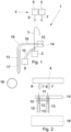
- the schematically illustrated warp knitting machine 1 has a knitting needle bar 2 which carries knitting needles 3, which can also be referred to as "working needles". Furthermore, a guide bar arrangement 4 is provided which has a weft thread guide bar 5 and one or more other guide bars 6.
- the weft thread guide bar 5 is provided with thread guides 7 which guide a weft thread during the production of a knitted fabric.
- the remaining guide bars 6 are provided with thread guides 8 which, together with the knitting needles 3, form a fringe.
- the thread guides 7 of the weft thread guide bar 5 then guide a weft thread back and forth between the individual fringe threads.
- Other types of laying than “fringe” are also possible, as long as a thread-like training.
- the term “fringe” is chosen here for reasons of simplicity.
- the warp knitting machine 1 further comprises a milling plate bar 9 with a milling plate 10. As can be seen in Fig.2 As can be seen, the milling plate 10 has milling plate teeth 11.
- the knitting needles 3 are arranged, for example, with a pitch of E1, i.e. one knitting needle 3 is arranged per inch of width (2.54 mm width).
- the pitch of the thread guides 7, 8 is corresponding.
- E6 or E12 it is also possible to choose a different fineness, for example E6 or E12, in which six or twelve knitting needles 3 and a corresponding number of thread guides 7, 8 are arranged per inch (2.54 mm).
- the knitting needles at a different distance, for example one knitting needle per two inches (50.8 mm) and a corresponding number of thread guides.
- Guide plates 12, 13 are arranged on both sides of each knitting needle 3 and are arranged on a guide plate bar 14.
- the guide plate bar 14 can be adjusted in the direction of a double arrow 15.
- An adjustment drive (not shown in detail) can be provided for this adjustment, so that the position of the guide plate bar 14 can be adjusted without the intervention of an operator.
- the guide plate bar 14 does not have to be moved to form a stitch. However, adjustment during operation of the warp knitting machine is possible.
- Each knitting needle 3 is assigned two guide plates 12, 13, whereby the two guide plates 12, 13 are arranged on both sides of the knitting needle 3. They are relatively close to the respective knitting needle 3 and can thus fulfil the function of a piercing comb, ie they can prevent the stitch from rising on the shaft of the knitting needle 3 when the knitting needle 3 rises.
- the guide plates 12, 13 are each arranged at positions where a milling plate tooth 11 is also located.
- the guide plates 12, 13 have the same width as the milling plate teeth 11, ie the same extension in the offset direction. Accordingly, Fig.2 the milling plate teeth 11 covered by the guide plates 12, 13 are shown in dashed lines.
- the milling plate 10 with its milling plate teeth 11 is arranged between the guide plates 12, 13 and the knitting needle bar 2.
- Fig.1 only the guide plate 13 is visible because the other guide plate 12 assigned to the same knitting needle 3 is covered by the guide plate 13.
- the guide plate 13 (the same applies to the guide plate 12) has a first section 16 which extends transversely to the offset direction in a first direction.
- the guide plate 13 also has a second section 17 which extends in the direction of a fabric take-off 18 onto which the fabric produced is wound.
- the first section 16 and the second section 17 are connected to one another by an arc section 19.
- Fig.1 It is shown that the second section 17 runs at right angles to the first section 16. This is not absolutely necessary. Other angles are possible.
- Fig.2 shows a warp knitting machine with a single loop-forming guide bar 6.
- the thread guides 8 together with the knitting needles 3 produce fringes or fringe threads.
- a connection between adjacent fringe threads is then made by the weft thread, which is guided by the weft thread guides 7 on the weft thread guide bar 5.
- the weft thread guides 7 guide the weft thread from one knitting needle 3 to the adjacent knitting needle 3 and back again to the first knitting needle 3.
- the weft thread is always incorporated into a fringe thread.
- the weft guide 7 guides the weft thread from the Fig.2 knitting needle 3 shown on the right to the Fig.2 the knitting needle 3 shown on the left, then the weft thread is first guided over the guide plate 12, then between the guide plate 12 and the guide plate 13 and finally over the guide plate 13 to the left knitting needle 3. During this movement of the weft thread, the knitted fabric is pulled off by the fabric take-up 18 and thus transported further.
- the second sections 17 of the guide plates 12, 13 are designed so long that the weft thread can lie on the guide plates 12, 13 until it is tied into the fringe threads at both ends.
- the length of the first section 16 can be used - to put it simply - to define the excess of the weft thread, i.e. the length of the weft thread that is formed in addition to the distance between two fringe threads.
- the guide plate bar 14 is adjustable transversely to the offset direction, it is possible to adjust the extent to which the first section 16 of the guide plates 12, 13 protrudes beyond the knitting needles 3. This also allows the length of the excess weft thread to be adjusted.
- the guide plate bar 14 can be adjusted, for example, via a central adjustment. The adjustment can also be made during the production of a Knitted fabrics can be produced in such a way that the knitted fabric then has areas with weft threads of different lengths in the longitudinal or take-up direction.
- the offset direction is the direction in which the guide bars 5, 6 of the guide bar arrangement 4 are moved to form the stitch.
- the offset direction corresponds to the longitudinal extension of the guide bar arrangement, related to the Fig.1 i.e. perpendicular to the drawing plane.
- Fig. 3 and 4 show a modified embodiment of a warp knitting machine 1 in the same representation as the Fig. 1 and 2 . Same elements as in the Fig. 1 and 2 are provided with the same reference symbols.
- a single stitch-forming guide bar 6 is present, which can produce a fringe, are in the design according to the Fig. 3 and 4
- Two stitch-forming guide bars 6, 6' with corresponding thread guides 8, 8' are provided, with which a tricot lay can be created. This allows an inherently stable stitch system to be formed into which the weft thread can be securely integrated.
- the two or more guide bars 6, 6' can also be used in a warp knitting machine whose knitting range corresponds to that in Fig.2 corresponds to the effective range shown.
Landscapes
- Engineering & Computer Science (AREA)
- Textile Engineering (AREA)
- Knitting Machines (AREA)
Priority Applications (3)
| Application Number | Priority Date | Filing Date | Title |
|---|---|---|---|
| PL21200087.1T PL4159905T3 (pl) | 2021-09-30 | 2021-09-30 | Dziewiarka osnowowa |
| EP21200087.1A EP4159905B1 (de) | 2021-09-30 | 2021-09-30 | Kettenwirkmaschine |
| CN202210224099.8A CN115897044A (zh) | 2021-09-30 | 2022-03-09 | 经编机 |
Applications Claiming Priority (1)
| Application Number | Priority Date | Filing Date | Title |
|---|---|---|---|
| EP21200087.1A EP4159905B1 (de) | 2021-09-30 | 2021-09-30 | Kettenwirkmaschine |
Publications (3)
| Publication Number | Publication Date |
|---|---|
| EP4159905A1 EP4159905A1 (de) | 2023-04-05 |
| EP4159905B1 true EP4159905B1 (de) | 2024-06-12 |
| EP4159905C0 EP4159905C0 (de) | 2024-06-12 |
Family
ID=78087024
Family Applications (1)
| Application Number | Title | Priority Date | Filing Date |
|---|---|---|---|
| EP21200087.1A Active EP4159905B1 (de) | 2021-09-30 | 2021-09-30 | Kettenwirkmaschine |
Country Status (3)
| Country | Link |
|---|---|
| EP (1) | EP4159905B1 (pl) |
| CN (1) | CN115897044A (pl) |
| PL (1) | PL4159905T3 (pl) |
Families Citing this family (1)
| Publication number | Priority date | Publication date | Assignee | Title |
|---|---|---|---|---|
| CN116892083A (zh) * | 2023-08-07 | 2023-10-17 | 镇江市中电电力设备有限公司 | 一种包装网生产装置及使用该装置的生产方法 |
Family Cites Families (6)
| Publication number | Priority date | Publication date | Assignee | Title |
|---|---|---|---|---|
| DE4301232C2 (de) * | 1993-01-19 | 1996-07-25 | Textilma Ag | Verfahren und Einrichtung zur Herstellung textiler netzartiger Flächengebilde |
| CA2251235C (en) | 1997-11-25 | 2006-09-05 | Yuval Leiber | Modified shuss knitted netting |
| GR1007649B (el) * | 2011-03-10 | 2012-07-13 | Καρατζη Βιομηχανικες Ξενοδοχειακες Επιχειρησεις Α.Ε., | Μεθοδος κατασκευης και παραγωγης υπερπλατη ελαστικου ή μη ελαστικου ιστου (διχτυ) για την συσκευασια παντος ειδους βιομηχανικων και γεωργικων προϊοντων |
| JP2018028158A (ja) * | 2016-08-18 | 2018-02-22 | 松山毛織株式会社 | ラップネット及びその製造方法 |
| WO2020027005A1 (ja) * | 2018-07-30 | 2020-02-06 | 岡本レース株式会社 | ロール状ラッピングネットの製造方法、及びロール状ラッピングネットの製造装置、及びロール状ラッピングネット |
| CN111101285B (zh) * | 2020-02-21 | 2024-08-16 | 福建省鑫港纺织机械有限公司 | 一种坯布幅宽大于经编机宽度的部分衬纬经编机 |
-
2021
- 2021-09-30 PL PL21200087.1T patent/PL4159905T3/pl unknown
- 2021-09-30 EP EP21200087.1A patent/EP4159905B1/de active Active
-
2022
- 2022-03-09 CN CN202210224099.8A patent/CN115897044A/zh active Pending
Also Published As
| Publication number | Publication date |
|---|---|
| CN115897044A (zh) | 2023-04-04 |
| PL4159905T3 (pl) | 2024-10-28 |
| EP4159905A1 (de) | 2023-04-05 |
| EP4159905C0 (de) | 2024-06-12 |
Similar Documents
| Publication | Publication Date | Title |
|---|---|---|
| DE3343048C2 (de) | Verfahren und Vorrichtung zum Legen von Querschußfäden für eine Kettenwirkmaschine | |
| DE102013012323B4 (de) | Verfahren zum Stricken von Gestricken | |
| EP2664701B1 (de) | Verfahren zur Herstellung eines Gestricks mit mindestens einem Flottfaden sowie damit hergestelltes Gestrick | |
| DE3935763A1 (de) | Flachstrickmaschine | |
| DD217553B3 (de) | Verfahren und vorrichtung zum herstellen einer textilbahn | |
| EP4159905B1 (de) | Kettenwirkmaschine | |
| DE19615671C2 (de) | Vorrichtung zur Herstellung von Kettenwirkware mit zwei voneinander unabhängigen Wirkbereichen | |
| EP0748889A2 (de) | Verfahren zur Herstellung einer Abstandswirkware sowie danach hergestellte Abstandswirkware | |
| EP1801277B1 (de) | Vorrichtung zur Erzeugung eines Abstandsgestricks | |
| DE19740200C1 (de) | Kettenwirkmaschine mit Legeschienen | |
| EP3530790B1 (de) | Schiebernadel | |
| EP3276062B1 (de) | Kettenwirkmaschine und verfahren zum herstellen einer kettenwirkware | |
| EP2770097B1 (de) | Verfahren zur herstellung einer schlingenware, kettenwirkmaschine und schieberbarre | |
| DE2908028C2 (de) | Kettenwirkmaschine zur Herstellung jacquardgemusterter Polgewirke | |
| EP3741892B1 (de) | Webmaschine zur herstellung von webgut mit eingearbeiteten effektfäden | |
| DE2443936C3 (de) | Kettengewirktes Vorhangband mit Schlitzen | |
| DE166161C (pl) | ||
| DE19739540C1 (de) | Verfahren und Vorrichtung zur Herstellung einer gemusterten Wirkware | |
| DE69622242T2 (de) | Verfahren zum Verbreitern von einem rund gestrickten Stoff unter Verwendung von einer Flachstrickmaschine | |
| DE69504605T2 (de) | Platinenanordnung in einer Strickmaschine und Verfahren zur Herstellung eines Gestricks durch Anwendung dieser Anordnung | |
| EP0179072B1 (de) | Verfahren zur herstellung eines gemusterten kettengewirkes und kettenwirkmaschine zur ausführung des verfahrens | |
| WO1988002038A1 (fr) | Tissu tricote en chaine et metier a tricoter a fil de trame pour produire le tissu tricote en chaine | |
| EP3702504B1 (de) | Kettenwirkmaschine, schiebernadelanordnung und verfahren zum herstellen einer elastischen wirkware | |
| DE4312706A1 (de) | Kettenwirkware mit Pol sowie Verfahren und Kettenwirkmaschine zu deren Herstellung | |
| EP3354780B1 (de) | Kettenwirkmaschine |
Legal Events
| Date | Code | Title | Description |
|---|---|---|---|
| PUAI | Public reference made under article 153(3) epc to a published international application that has entered the european phase |
Free format text: ORIGINAL CODE: 0009012 |
|
| STAA | Information on the status of an ep patent application or granted ep patent |
Free format text: STATUS: REQUEST FOR EXAMINATION WAS MADE |
|
| 17P | Request for examination filed |
Effective date: 20220829 |
|
| AK | Designated contracting states |
Kind code of ref document: A1 Designated state(s): AL AT BE BG CH CY CZ DE DK EE ES FI FR GB GR HR HU IE IS IT LI LT LU LV MC MK MT NL NO PL PT RO RS SE SI SK SM TR |
|
| P01 | Opt-out of the competence of the unified patent court (upc) registered |
Effective date: 20230705 |
|
| GRAP | Despatch of communication of intention to grant a patent |
Free format text: ORIGINAL CODE: EPIDOSNIGR1 |
|
| STAA | Information on the status of an ep patent application or granted ep patent |
Free format text: STATUS: GRANT OF PATENT IS INTENDED |
|
| RIC1 | Information provided on ipc code assigned before grant |
Ipc: D04B 27/06 20060101ALI20240102BHEP Ipc: D04B 27/04 20060101ALI20240102BHEP Ipc: D04B 23/22 20060101ALI20240102BHEP Ipc: D04B 23/12 20060101ALI20240102BHEP Ipc: D04B 21/10 20060101ALI20240102BHEP Ipc: D04B 23/00 20060101ALI20240102BHEP Ipc: D04B 27/00 20060101ALI20240102BHEP Ipc: D04B 21/00 20060101AFI20240102BHEP |
|
| INTG | Intention to grant announced |
Effective date: 20240205 |
|
| GRAS | Grant fee paid |
Free format text: ORIGINAL CODE: EPIDOSNIGR3 |
|
| GRAA | (expected) grant |
Free format text: ORIGINAL CODE: 0009210 |
|
| STAA | Information on the status of an ep patent application or granted ep patent |
Free format text: STATUS: THE PATENT HAS BEEN GRANTED |
|
| AK | Designated contracting states |
Kind code of ref document: B1 Designated state(s): AL AT BE BG CH CY CZ DE DK EE ES FI FR GB GR HR HU IE IS IT LI LT LU LV MC MK MT NL NO PL PT RO RS SE SI SK SM TR |
|
| REG | Reference to a national code |
Ref country code: GB Ref legal event code: FG4D Free format text: NOT ENGLISH |
|
| REG | Reference to a national code |
Ref country code: CH Ref legal event code: EP |
|
| REG | Reference to a national code |
Ref country code: IE Ref legal event code: FG4D Free format text: LANGUAGE OF EP DOCUMENT: GERMAN |
|
| REG | Reference to a national code |
Ref country code: DE Ref legal event code: R096 Ref document number: 502021003979 Country of ref document: DE |
|
| U01 | Request for unitary effect filed |
Effective date: 20240704 |
|
| U07 | Unitary effect registered |
Designated state(s): AT BE BG DE DK EE FI FR IT LT LU LV MT NL PT SE SI Effective date: 20240715 |
|
| P04 | Withdrawal of opt-out of the competence of the unified patent court (upc) registered |
Free format text: CASE NUMBER: APP_41020/2024 Effective date: 20240710 |
|
| PG25 | Lapsed in a contracting state [announced via postgrant information from national office to epo] |
Ref country code: HR Free format text: LAPSE BECAUSE OF FAILURE TO SUBMIT A TRANSLATION OF THE DESCRIPTION OR TO PAY THE FEE WITHIN THE PRESCRIBED TIME-LIMIT Effective date: 20240612 |
|
| PG25 | Lapsed in a contracting state [announced via postgrant information from national office to epo] |
Ref country code: ES Free format text: LAPSE BECAUSE OF FAILURE TO SUBMIT A TRANSLATION OF THE DESCRIPTION OR TO PAY THE FEE WITHIN THE PRESCRIBED TIME-LIMIT Effective date: 20240612 |
|
| U20 | Renewal fee for the european patent with unitary effect paid |
Year of fee payment: 4 Effective date: 20240926 |
|
| PG25 | Lapsed in a contracting state [announced via postgrant information from national office to epo] |
Ref country code: NO Free format text: LAPSE BECAUSE OF FAILURE TO SUBMIT A TRANSLATION OF THE DESCRIPTION OR TO PAY THE FEE WITHIN THE PRESCRIBED TIME-LIMIT Effective date: 20240912 Ref country code: HR Free format text: LAPSE BECAUSE OF FAILURE TO SUBMIT A TRANSLATION OF THE DESCRIPTION OR TO PAY THE FEE WITHIN THE PRESCRIBED TIME-LIMIT Effective date: 20240612 Ref country code: ES Free format text: LAPSE BECAUSE OF FAILURE TO SUBMIT A TRANSLATION OF THE DESCRIPTION OR TO PAY THE FEE WITHIN THE PRESCRIBED TIME-LIMIT Effective date: 20240612 Ref country code: RS Free format text: LAPSE BECAUSE OF FAILURE TO SUBMIT A TRANSLATION OF THE DESCRIPTION OR TO PAY THE FEE WITHIN THE PRESCRIBED TIME-LIMIT Effective date: 20240912 |
|
| REG | Reference to a national code |
Ref country code: GR Ref legal event code: EP Ref document number: 20240402084 Country of ref document: GR Effective date: 20241111 |
|
| P05 | Withdrawal of opt-out of the competence of the unified patent court (upc) changed |
Free format text: CASE NUMBER: APP_41020/2024 Effective date: 20240715 |
|
| PG25 | Lapsed in a contracting state [announced via postgrant information from national office to epo] |
Ref country code: IS Free format text: LAPSE BECAUSE OF FAILURE TO SUBMIT A TRANSLATION OF THE DESCRIPTION OR TO PAY THE FEE WITHIN THE PRESCRIBED TIME-LIMIT Effective date: 20241012 |
|
| PG25 | Lapsed in a contracting state [announced via postgrant information from national office to epo] |
Ref country code: RO Free format text: LAPSE BECAUSE OF FAILURE TO SUBMIT A TRANSLATION OF THE DESCRIPTION OR TO PAY THE FEE WITHIN THE PRESCRIBED TIME-LIMIT Effective date: 20240612 Ref country code: SK Free format text: LAPSE BECAUSE OF FAILURE TO SUBMIT A TRANSLATION OF THE DESCRIPTION OR TO PAY THE FEE WITHIN THE PRESCRIBED TIME-LIMIT Effective date: 20240612 |
|
| PG25 | Lapsed in a contracting state [announced via postgrant information from national office to epo] |
Ref country code: SM Free format text: LAPSE BECAUSE OF FAILURE TO SUBMIT A TRANSLATION OF THE DESCRIPTION OR TO PAY THE FEE WITHIN THE PRESCRIBED TIME-LIMIT Effective date: 20240612 |
|
| PG25 | Lapsed in a contracting state [announced via postgrant information from national office to epo] |
Ref country code: SM Free format text: LAPSE BECAUSE OF FAILURE TO SUBMIT A TRANSLATION OF THE DESCRIPTION OR TO PAY THE FEE WITHIN THE PRESCRIBED TIME-LIMIT Effective date: 20240612 Ref country code: SK Free format text: LAPSE BECAUSE OF FAILURE TO SUBMIT A TRANSLATION OF THE DESCRIPTION OR TO PAY THE FEE WITHIN THE PRESCRIBED TIME-LIMIT Effective date: 20240612 Ref country code: RO Free format text: LAPSE BECAUSE OF FAILURE TO SUBMIT A TRANSLATION OF THE DESCRIPTION OR TO PAY THE FEE WITHIN THE PRESCRIBED TIME-LIMIT Effective date: 20240612 Ref country code: IS Free format text: LAPSE BECAUSE OF FAILURE TO SUBMIT A TRANSLATION OF THE DESCRIPTION OR TO PAY THE FEE WITHIN THE PRESCRIBED TIME-LIMIT Effective date: 20241012 |
|
| PLBE | No opposition filed within time limit |
Free format text: ORIGINAL CODE: 0009261 |
|
| STAA | Information on the status of an ep patent application or granted ep patent |
Free format text: STATUS: NO OPPOSITION FILED WITHIN TIME LIMIT |
|
| PG25 | Lapsed in a contracting state [announced via postgrant information from national office to epo] |
Ref country code: MC Free format text: LAPSE BECAUSE OF FAILURE TO SUBMIT A TRANSLATION OF THE DESCRIPTION OR TO PAY THE FEE WITHIN THE PRESCRIBED TIME-LIMIT Effective date: 20240612 |
|
| REG | Reference to a national code |
Ref country code: CH Ref legal event code: PL |
|
| 26N | No opposition filed |
Effective date: 20250313 |
|
| PG25 | Lapsed in a contracting state [announced via postgrant information from national office to epo] |
Ref country code: CH Free format text: LAPSE BECAUSE OF NON-PAYMENT OF DUE FEES Effective date: 20240930 |
|
| PG25 | Lapsed in a contracting state [announced via postgrant information from national office to epo] |
Ref country code: IE Free format text: LAPSE BECAUSE OF NON-PAYMENT OF DUE FEES Effective date: 20240930 |
|
| PGFP | Annual fee paid to national office [announced via postgrant information from national office to epo] |
Ref country code: GR Payment date: 20250923 Year of fee payment: 5 |
|
| PGFP | Annual fee paid to national office [announced via postgrant information from national office to epo] |
Ref country code: TR Payment date: 20250917 Year of fee payment: 5 Ref country code: PL Payment date: 20250922 Year of fee payment: 5 |
|
| PGFP | Annual fee paid to national office [announced via postgrant information from national office to epo] |
Ref country code: CZ Payment date: 20250918 Year of fee payment: 5 |
|
| U20 | Renewal fee for the european patent with unitary effect paid |
Year of fee payment: 5 Effective date: 20250925 |
|
| PG25 | Lapsed in a contracting state [announced via postgrant information from national office to epo] |
Ref country code: CY Free format text: LAPSE BECAUSE OF FAILURE TO SUBMIT A TRANSLATION OF THE DESCRIPTION OR TO PAY THE FEE WITHIN THE PRESCRIBED TIME-LIMIT; INVALID AB INITIO Effective date: 20210930 |