EP4157583B1 - Tools - Google Patents
Tools Download PDFInfo
- Publication number
- EP4157583B1 EP4157583B1 EP21729958.5A EP21729958A EP4157583B1 EP 4157583 B1 EP4157583 B1 EP 4157583B1 EP 21729958 A EP21729958 A EP 21729958A EP 4157583 B1 EP4157583 B1 EP 4157583B1
- Authority
- EP
- European Patent Office
- Prior art keywords
- engagement part
- power head
- pin
- bore
- compressible
- Prior art date
- Legal status (The legal status is an assumption and is not a legal conclusion. Google has not performed a legal analysis and makes no representation as to the accuracy of the status listed.)
- Active
Links
Images


Classifications
-
- B—PERFORMING OPERATIONS; TRANSPORTING
- B25—HAND TOOLS; PORTABLE POWER-DRIVEN TOOLS; MANIPULATORS
- B25B—TOOLS OR BENCH DEVICES NOT OTHERWISE PROVIDED FOR, FOR FASTENING, CONNECTING, DISENGAGING OR HOLDING
- B25B21/00—Portable power-driven screw or nut setting or loosening tools; Attachments for drilling apparatus serving the same purpose
- B25B21/004—Portable power-driven screw or nut setting or loosening tools; Attachments for drilling apparatus serving the same purpose of the ratchet type
- B25B21/005—Portable power-driven screw or nut setting or loosening tools; Attachments for drilling apparatus serving the same purpose of the ratchet type driven by a radially acting hydraulic or pneumatic piston
-
- B—PERFORMING OPERATIONS; TRANSPORTING
- B25—HAND TOOLS; PORTABLE POWER-DRIVEN TOOLS; MANIPULATORS
- B25B—TOOLS OR BENCH DEVICES NOT OTHERWISE PROVIDED FOR, FOR FASTENING, CONNECTING, DISENGAGING OR HOLDING
- B25B23/00—Details of, or accessories for, spanners, wrenches, screwdrivers
- B25B23/0007—Connections or joints between tool parts
Definitions
- This invention relates to tools, particularly engagement parts of tools such as, non-exclusively, hydraulic wrenches.
- Atlas Copco provide an RTX hexagon drive hydraulic wrench, as do other suppliers, which comprise a releasable power head that can engage a ratchet link which itself engages the workpiece (typically a hex nut or hex head of a bolt or the like).
- the power head provides motion derived from hydraulic power, and the ratchet link converts that motion into rotation of the workpiece.
- a releasable mounting of some description can be used.
- that may comprise a fixed part (e.g. a fixed pin working in a slot) and a releasable part (such a releasable pin working in a bore, removal of the pin allowing release of the two parts).
- an engagement part of a tool the engagement part being arranged to engage a workpiece and a power head, the engagement part being arranged to convert movement generated by the power head into movement of the workpiece
- the engagement part comprising a mounting for the power head, the mounting comprising a moveable portion moveable from a first position where the power head is fixed relative to the engagement part and a second position where the power head can move relative to the engagement part
- the moveable portion comprising a pin having a length and slidable along its length in a bore in the engagement part and a friction lock comprising a compressible member and a compressing member arranged to compress the compressible member, the compressible member being arranged such that it expands in at least one extent on compression by the compressing member such that in a locked position of the friction lock, the compressible member extends so as contact the pin so as to restrict movement of the pin.
- this provides for a pin that is positively retained in place by a frictional engagement of a compressible member that is urged into place by the action of a user. As such, it is less likely that the pin will unintentionally fall out of the engagement part than solely relying on, for example, a spring-biased ball bearing working in a groove in the pin.
- the pin may be sized and shaped so as to pass through a part of the power head.
- the pin may have a consistent cross section over a portion of its length, the portion typically being a majority of the length.
- the cross section may be non-circular.
- the cross section would have a circumference and would comprise a first shape over a first portion of the circumference and a second shape over a second portion of the circumference.
- the first and second shapes would be non-concentric circular arcs, with a centre of the arc forming the second shape being outside of the cross section. As such, this describes a generally cylindrical pin with a crescent-shaped key taken out and is easy to machine.
- the portion of the length may not extend to a retained end of the pin, which is held captive in the bore by at least the compressible member, if not also the compression member.
- the retained end may have a cross section of the first shape.
- the compressible member may be arranged to engage the pin at the second portion of the circumference.
- the compressible member may have an outer circumference complementary to the second shape; as such, the compressible member may be circular, and may have a variable radius depending on a degree of compression applied to the compressible member by the compression member, with the compressible member typically frictionally engaging the pin over the second shape in the locked position.
- the compressible member may comprise a compressible washer
- the compression member may comprise a threaded stud and a head, the head providing a flange which bears onto the compressible washer.
- the threaded stud be mounted in a threaded bore in the engagement part; typically the threaded bore will be parallel to the bore, which again is easy to manufacture.
- the head may act to hold the retained end captive in the bore.
- the compressible washer may be formed from a resilient and in particular elastomeric material, such as polyurethane.
- the pin may comprise a circumferential groove around its circumference, which can be engaged by a biased member in the power head.
- This provides further redundancy in retaining the pin and provides a positive confirmation to the user that the pin is in the appropriate position when they can feel the biased member entering the groove.
- the mounting of the engagement part may comprise a fixed portion in addition to the moveable portion, the fixed portion providing a fixed location for the power head.
- the fixed portion may comprise a slot for a pin of the power head.
- the workpiece will comprise a hex head of a bolt or a hexagonal nut.
- the engagement part may comprise a hex drive for driving hex bolts or nuts.
- the hex drive may be a ratchet hex drive, in that it can only turn in a single rotational sense, the rotational sense being optionally selectable by a user.
- the power head may be a hydraulic power head.
- a tool comprising the engagement part of the first aspect of the invention, and a power head, the power head being engaged on the mounting such that the power head is able to provide the engagement part with motive force to move the workpiece.
- the tool may be, for example, a hydraulic wrench; as such, the power head may be a hydraulic power head.
- the power head may comprise a bore for the pin.
- the power head may further comprise a biasing member and a biased member, the biasing member tending to bias the biased member into engagement with the groove in the pin through a wall of the bore in the power head in the first position of the movable portion.
- the biased member would be held captive in the power head, typically by working in a further bore in the power head having an aperture into the bore in which the pin works, with a diameter of the aperture being less than a diameter of the biased member.
- the biased member would comprise a spherical member such as a ball bearing, and the biasing member would comprise a spring in the further bore.
- kit of components for forming into a tool comprising at least three components selected from the following group, at least one of each of the elements being chosen:
- this provides an interchangeable system of power heads and engagement part that can be used for difference uses (e.g. different sized workpieces, different force or power requirements).
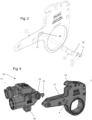
- the accompanying drawings show a hydraulic wrench 10 that is formed of a ratchet link 1 (otherwise described above as an engagement part) to which is removably coupled a power head 11.
- the power head uses a hydraulic power source to generate motion of a piston rod end 12; this acts upon the ratchet link 1 and is used to rotate a hex drive 13, which can rotate a hexagonally shaped workpiece such as a hexagonal bolt head or nut.
- a mounting is provided. This comprises a fixed slot 14 in the ratchet link 1 which receives a fixed pin 15 on the power head 11, and a sliding pin 4 working in a first bore 17 in the ratchet link 1 and which is received in a bore 16 on the power head 11.
- the power head 11 and ratchet link 1 are fixed together. To release those two parts, the sliding pin 4 is withdrawn from the bore 16 in the power head 11 and the power head can then be removed from the ratchet link 1.
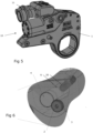
- a friction lock is provided. This comprises a threaded screw 2 having a larger diameter head 5 and a compressible washer 3. The threaded screw 2 works in second, threaded bore 18 in the ratchet link 1 parallel to the first bore 17 (and therefore convenient to machine).
- the cross section of the pin 4 is circular, but (apart from at end 21 as explained below) with a part-circular cutout 19 roughly coaxial with the second bore 18.
- the friction lock acts on the cutout 19.
- the compressible washer 3 is made of a material which, when compressed by the screw 2 (and in particular the flange formed by the head 5 of the screw), expands, in particular radially outwards from the second bore 18. This means that if the user screws screw 2 into the second bore to its fullest extent, the compressible washer 3 will expand outwards as far as possible, engaging the pin 4 and preventing, or at least restricting, its withdrawal. If desired, the user could unscrew the screw 2, such that the compression on compressible washer 3 reduces, and its radial extent decreases. The pin 4 can then be free to be removed to allow for the removal of power head 11 from ratchet link 1. However, it is envisaged that the friction lock will provide frictional force such that the user could remove the pin against the frictional force generated by the friction lock, but unintentional removal or escaping will be inhibited.
- the cutout 19 does not extend the entire length of the pin 4, and is not present at the end 21 retained in the ratchet link 1, where the pin 4 is entirely circular. As such, the pin 4 cannot pass the screw 2 and washer 3 with the screw in place. This prevents the pin 4 unintentionally dropping out.
- the power head 11 is also provided with a spring-loaded ball 20 which works through an aperture in the bore 16 to be received within a groove 6 in the pin. This can assist with retaining the pin 4 in the power head 11 and ratchet link 1 and can provide a user with positive feedback that the pin has been inserted into the correct location, as it will be possible to feel the ball 20 engage the groove 6. However, this is merely a backup to the friction lock.
- the pin 4 can be prevented or restricted from sliding out in use; tool reliability is increased because the pin cannot (or is less likely) to disengage from the power head 11.
- the pin 4 is less likely to drop out and potentially form a drop hazard than, say, a prior art spring-loaded ball. Having the first and second bores parallel means that they are easy to machine.
Landscapes
- Engineering & Computer Science (AREA)
- Mechanical Engineering (AREA)
- Snaps, Bayonet Connections, Set Pins, And Snap Rings (AREA)
- Clamps And Clips (AREA)
- Connection Of Plates (AREA)
Applications Claiming Priority (2)
| Application Number | Priority Date | Filing Date | Title |
|---|---|---|---|
| GB2008035.4A GB2595500B (en) | 2020-05-28 | 2020-05-28 | Tools |
| PCT/IB2021/054678 WO2021240451A1 (en) | 2020-05-28 | 2021-05-28 | Tools |
Publications (3)
| Publication Number | Publication Date |
|---|---|
| EP4157583A1 EP4157583A1 (en) | 2023-04-05 |
| EP4157583B1 true EP4157583B1 (en) | 2024-01-31 |
| EP4157583C0 EP4157583C0 (en) | 2024-01-31 |
Family
ID=71526256
Family Applications (1)
| Application Number | Title | Priority Date | Filing Date |
|---|---|---|---|
| EP21729958.5A Active EP4157583B1 (en) | 2020-05-28 | 2021-05-28 | Tools |
Country Status (9)
| Country | Link |
|---|---|
| US (1) | US12280472B2 (pl) |
| EP (1) | EP4157583B1 (pl) |
| KR (1) | KR20230034233A (pl) |
| CN (1) | CN115776925B (pl) |
| BR (1) | BR112022024158A8 (pl) |
| ES (1) | ES2970658T3 (pl) |
| GB (1) | GB2595500B (pl) |
| PL (1) | PL4157583T3 (pl) |
| WO (1) | WO2021240451A1 (pl) |
Families Citing this family (1)
| Publication number | Priority date | Publication date | Assignee | Title |
|---|---|---|---|---|
| USD1042067S1 (en) * | 2023-02-28 | 2024-09-17 | Primesource Consulting Llc | Limited clearance tool |
Family Cites Families (16)
| Publication number | Priority date | Publication date | Assignee | Title |
|---|---|---|---|---|
| US4385533A (en) * | 1981-08-28 | 1983-05-31 | Collins Bobby W | Universal reaction plate |
| US4794825A (en) * | 1986-11-03 | 1989-01-03 | Atlantic-Caribbean Products, Inc. | Hydraulic power wrench |
| JPH03117567A (ja) * | 1989-09-29 | 1991-05-20 | Paul Heinz Wagner | 油圧パワーレンチ |
| DE4042070C2 (de) | 1990-01-13 | 1995-06-08 | Wagner Paul Heinz | Druckmittelbetriebener Kraftschrauber |
| US5201256A (en) * | 1992-04-06 | 1993-04-13 | The Brooklyn Union Gas Company | Power tool for torquing threaded pipes |
| US20020121161A1 (en) * | 2001-03-05 | 2002-09-05 | Peter Koppenhoefer | Fluid operated tool for tightening and loosening threaded connectors |
| CN2593967Y (zh) * | 2002-12-17 | 2003-12-24 | 江华葆 | 浮动传力臂式液压扳手 |
| US20060243100A1 (en) * | 2005-04-27 | 2006-11-02 | Jason Junkers | Nut, a tool and a method for elongating and relaxing a stud and the like |
| US9492912B2 (en) | 2013-02-22 | 2016-11-15 | Steven Spirer | Hydraulic torque wrench system |
| CN203726402U (zh) * | 2014-03-19 | 2014-07-23 | 杜德机械科技(上海)有限公司 | 液压扳手 |
| CN204076104U (zh) * | 2014-09-19 | 2015-01-07 | 蔡培琴 | 具有夹掣装置的扳手 |
| DE102015011553A1 (de) * | 2015-09-02 | 2017-03-02 | Jörg Hohmann | Drehmomentschrauber |
| GB2558536A (en) * | 2016-11-14 | 2018-07-18 | Torque Tension Systems Ltd | A hydraulic torque wrench |
| CN206426027U (zh) * | 2017-01-16 | 2017-08-22 | 杭州雷恩液压设备制造有限公司 | 棘轮液压扳手 |
| CN206484473U (zh) * | 2017-01-17 | 2017-09-12 | 海恩拓克工业装备(武汉)有限公司 | 一种多功能液压扳手 |
| GB2573169A (en) * | 2018-04-27 | 2019-10-30 | Hire Torque Ltd | A drive link |
-
2020
- 2020-05-28 GB GB2008035.4A patent/GB2595500B/en not_active Expired - Fee Related
-
2021
- 2021-05-28 ES ES21729958T patent/ES2970658T3/es active Active
- 2021-05-28 CN CN202180046914.XA patent/CN115776925B/zh active Active
- 2021-05-28 US US17/928,053 patent/US12280472B2/en active Active
- 2021-05-28 BR BR112022024158A patent/BR112022024158A8/pt unknown
- 2021-05-28 WO PCT/IB2021/054678 patent/WO2021240451A1/en not_active Ceased
- 2021-05-28 PL PL21729958.5T patent/PL4157583T3/pl unknown
- 2021-05-28 KR KR1020227046101A patent/KR20230034233A/ko active Pending
- 2021-05-28 EP EP21729958.5A patent/EP4157583B1/en active Active
Also Published As
| Publication number | Publication date |
|---|---|
| BR112022024158A2 (pt) | 2022-12-27 |
| PL4157583T3 (pl) | 2024-09-02 |
| US20230211478A1 (en) | 2023-07-06 |
| EP4157583A1 (en) | 2023-04-05 |
| CN115776925A (zh) | 2023-03-10 |
| US12280472B2 (en) | 2025-04-22 |
| ES2970658T3 (es) | 2024-05-30 |
| GB2595500A (en) | 2021-12-01 |
| CN115776925B (zh) | 2026-01-02 |
| WO2021240451A1 (en) | 2021-12-02 |
| GB202008035D0 (en) | 2020-07-15 |
| BR112022024158A8 (pt) | 2023-01-24 |
| KR20230034233A (ko) | 2023-03-09 |
| EP4157583C0 (en) | 2024-01-31 |
| GB2595500B (en) | 2024-02-14 |
Similar Documents
| Publication | Publication Date | Title |
|---|---|---|
| US20020122703A1 (en) | Quick change adaptor for hole saw | |
| US8651198B2 (en) | Spindle lock devices for screwdrivers | |
| US7272998B1 (en) | Torque-limiting mechanism | |
| US20090255386A1 (en) | Torque Socket | |
| US12447591B1 (en) | Torque driver | |
| EP4157583B1 (en) | Tools | |
| EP1329293A2 (en) | Adjustable reaction arm for torque power tool and torque power tool provided therewith | |
| JP6599724B2 (ja) | 動力工具用の保持および解放機構 | |
| WO2022040755A1 (en) | Fasteners, fastener arrangements and tools for application and/or release of fasteners | |
| US20250170635A1 (en) | Knockout Punch Tool with Draw Stud | |
| CN112388342B (zh) | 防松夹紧的夹头结构 | |
| WO2018126297A1 (en) | A segmented nut and a device for use in releasing nut type fasteners | |
| CN113027905B (zh) | 扭力结构 | |
| US20080247840A1 (en) | Fastener and Fastener Tightening/Loosening Device | |
| KR20180130224A (ko) | 전기 드릴용 육각 원터치 척. | |
| AU2014305944A1 (en) | Apparatus for tightening threaded fasteners | |
| US6952865B2 (en) | Apparatus for removing heavy duty brake drum bolts | |
| US20180354110A1 (en) | Releasable sef-locking device and method for using same to replace bushings | |
| CN112901621A (zh) | 一种多用膨胀螺丝及拧紧工具 | |
| CA2970028A1 (en) | Releasable self-locking device and method for using same to replace bushings | |
| AU2010202279B2 (en) | Fastener | |
| WO1994017312A1 (en) | Pin assembly for a component | |
| EP4255679A1 (en) | Manual impact driver | |
| AU2006274500A1 (en) | Improved fastener and fastener tightening/loosening device | |
| HK1054205A (en) | Adjustable reaction arm for torque power tool and torque power tool provided therewith |
Legal Events
| Date | Code | Title | Description |
|---|---|---|---|
| STAA | Information on the status of an ep patent application or granted ep patent |
Free format text: STATUS: UNKNOWN |
|
| STAA | Information on the status of an ep patent application or granted ep patent |
Free format text: STATUS: THE INTERNATIONAL PUBLICATION HAS BEEN MADE |
|
| PUAI | Public reference made under article 153(3) epc to a published international application that has entered the european phase |
Free format text: ORIGINAL CODE: 0009012 |
|
| STAA | Information on the status of an ep patent application or granted ep patent |
Free format text: STATUS: REQUEST FOR EXAMINATION WAS MADE |
|
| 17P | Request for examination filed |
Effective date: 20221206 |
|
| AK | Designated contracting states |
Kind code of ref document: A1 Designated state(s): AL AT BE BG CH CY CZ DE DK EE ES FI FR GB GR HR HU IE IS IT LI LT LU LV MC MK MT NL NO PL PT RO RS SE SI SK SM TR |
|
| GRAP | Despatch of communication of intention to grant a patent |
Free format text: ORIGINAL CODE: EPIDOSNIGR1 |
|
| STAA | Information on the status of an ep patent application or granted ep patent |
Free format text: STATUS: GRANT OF PATENT IS INTENDED |
|
| DAV | Request for validation of the european patent (deleted) | ||
| DAX | Request for extension of the european patent (deleted) | ||
| INTG | Intention to grant announced |
Effective date: 20230824 |
|
| RIN1 | Information on inventor provided before grant (corrected) |
Inventor name: O'BRIEN, TERESA Inventor name: DODDS, TONY Inventor name: GILL, JOSEPH Inventor name: O'BRIEN, IAN |
|
| GRAS | Grant fee paid |
Free format text: ORIGINAL CODE: EPIDOSNIGR3 |
|
| GRAA | (expected) grant |
Free format text: ORIGINAL CODE: 0009210 |
|
| STAA | Information on the status of an ep patent application or granted ep patent |
Free format text: STATUS: THE PATENT HAS BEEN GRANTED |
|
| AK | Designated contracting states |
Kind code of ref document: B1 Designated state(s): AL AT BE BG CH CY CZ DE DK EE ES FI FR GB GR HR HU IE IS IT LI LT LU LV MC MK MT NL NO PL PT RO RS SE SI SK SM TR |
|
| REG | Reference to a national code |
Ref country code: GB Ref legal event code: FG4D Ref country code: CH Ref legal event code: EP |
|
| REG | Reference to a national code |
Ref country code: DE Ref legal event code: R096 Ref document number: 602021009060 Country of ref document: DE |
|
| REG | Reference to a national code |
Ref country code: IE Ref legal event code: FG4D |
|
| U01 | Request for unitary effect filed |
Effective date: 20240223 |
|
| U07 | Unitary effect registered |
Designated state(s): AT BE BG DE DK EE FI FR IT LT LU LV MT NL PT SE SI Effective date: 20240304 |
|
| U20 | Renewal fee for the european patent with unitary effect paid |
Year of fee payment: 4 Effective date: 20240313 |
|
| REG | Reference to a national code |
Ref country code: LT Ref legal event code: MG9D |
|
| REG | Reference to a national code |
Ref country code: ES Ref legal event code: FG2A Ref document number: 2970658 Country of ref document: ES Kind code of ref document: T3 Effective date: 20240530 |
|
| PG25 | Lapsed in a contracting state [announced via postgrant information from national office to epo] |
Ref country code: IS Free format text: LAPSE BECAUSE OF FAILURE TO SUBMIT A TRANSLATION OF THE DESCRIPTION OR TO PAY THE FEE WITHIN THE PRESCRIBED TIME-LIMIT Effective date: 20240531 |
|
| PG25 | Lapsed in a contracting state [announced via postgrant information from national office to epo] |
Ref country code: GR Free format text: LAPSE BECAUSE OF FAILURE TO SUBMIT A TRANSLATION OF THE DESCRIPTION OR TO PAY THE FEE WITHIN THE PRESCRIBED TIME-LIMIT Effective date: 20240501 |
|
| PG25 | Lapsed in a contracting state [announced via postgrant information from national office to epo] |
Ref country code: RS Free format text: LAPSE BECAUSE OF FAILURE TO SUBMIT A TRANSLATION OF THE DESCRIPTION OR TO PAY THE FEE WITHIN THE PRESCRIBED TIME-LIMIT Effective date: 20240430 Ref country code: HR Free format text: LAPSE BECAUSE OF FAILURE TO SUBMIT A TRANSLATION OF THE DESCRIPTION OR TO PAY THE FEE WITHIN THE PRESCRIBED TIME-LIMIT Effective date: 20240131 |
|
| PG25 | Lapsed in a contracting state [announced via postgrant information from national office to epo] |
Ref country code: RS Free format text: LAPSE BECAUSE OF FAILURE TO SUBMIT A TRANSLATION OF THE DESCRIPTION OR TO PAY THE FEE WITHIN THE PRESCRIBED TIME-LIMIT Effective date: 20240430 Ref country code: NO Free format text: LAPSE BECAUSE OF FAILURE TO SUBMIT A TRANSLATION OF THE DESCRIPTION OR TO PAY THE FEE WITHIN THE PRESCRIBED TIME-LIMIT Effective date: 20240430 Ref country code: IS Free format text: LAPSE BECAUSE OF FAILURE TO SUBMIT A TRANSLATION OF THE DESCRIPTION OR TO PAY THE FEE WITHIN THE PRESCRIBED TIME-LIMIT Effective date: 20240531 Ref country code: HR Free format text: LAPSE BECAUSE OF FAILURE TO SUBMIT A TRANSLATION OF THE DESCRIPTION OR TO PAY THE FEE WITHIN THE PRESCRIBED TIME-LIMIT Effective date: 20240131 Ref country code: GR Free format text: LAPSE BECAUSE OF FAILURE TO SUBMIT A TRANSLATION OF THE DESCRIPTION OR TO PAY THE FEE WITHIN THE PRESCRIBED TIME-LIMIT Effective date: 20240501 |
|
| PG25 | Lapsed in a contracting state [announced via postgrant information from national office to epo] |
Ref country code: SM Free format text: LAPSE BECAUSE OF FAILURE TO SUBMIT A TRANSLATION OF THE DESCRIPTION OR TO PAY THE FEE WITHIN THE PRESCRIBED TIME-LIMIT Effective date: 20240131 |
|
| PG25 | Lapsed in a contracting state [announced via postgrant information from national office to epo] |
Ref country code: CZ Free format text: LAPSE BECAUSE OF FAILURE TO SUBMIT A TRANSLATION OF THE DESCRIPTION OR TO PAY THE FEE WITHIN THE PRESCRIBED TIME-LIMIT Effective date: 20240131 |
|
| PG25 | Lapsed in a contracting state [announced via postgrant information from national office to epo] |
Ref country code: SK Free format text: LAPSE BECAUSE OF FAILURE TO SUBMIT A TRANSLATION OF THE DESCRIPTION OR TO PAY THE FEE WITHIN THE PRESCRIBED TIME-LIMIT Effective date: 20240131 |
|
| PG25 | Lapsed in a contracting state [announced via postgrant information from national office to epo] |
Ref country code: SM Free format text: LAPSE BECAUSE OF FAILURE TO SUBMIT A TRANSLATION OF THE DESCRIPTION OR TO PAY THE FEE WITHIN THE PRESCRIBED TIME-LIMIT Effective date: 20240131 Ref country code: SK Free format text: LAPSE BECAUSE OF FAILURE TO SUBMIT A TRANSLATION OF THE DESCRIPTION OR TO PAY THE FEE WITHIN THE PRESCRIBED TIME-LIMIT Effective date: 20240131 Ref country code: RO Free format text: LAPSE BECAUSE OF FAILURE TO SUBMIT A TRANSLATION OF THE DESCRIPTION OR TO PAY THE FEE WITHIN THE PRESCRIBED TIME-LIMIT Effective date: 20240131 Ref country code: CZ Free format text: LAPSE BECAUSE OF FAILURE TO SUBMIT A TRANSLATION OF THE DESCRIPTION OR TO PAY THE FEE WITHIN THE PRESCRIBED TIME-LIMIT Effective date: 20240131 |
|
| REG | Reference to a national code |
Ref country code: DE Ref legal event code: R097 Ref document number: 602021009060 Country of ref document: DE |
|
| PLBE | No opposition filed within time limit |
Free format text: ORIGINAL CODE: 0009261 |
|
| STAA | Information on the status of an ep patent application or granted ep patent |
Free format text: STATUS: NO OPPOSITION FILED WITHIN TIME LIMIT |
|
| REG | Reference to a national code |
Ref country code: CH Ref legal event code: PL |
|
| 26N | No opposition filed |
Effective date: 20241101 |
|
| PG25 | Lapsed in a contracting state [announced via postgrant information from national office to epo] |
Ref country code: MC Free format text: LAPSE BECAUSE OF FAILURE TO SUBMIT A TRANSLATION OF THE DESCRIPTION OR TO PAY THE FEE WITHIN THE PRESCRIBED TIME-LIMIT Effective date: 20240131 |
|
| PG25 | Lapsed in a contracting state [announced via postgrant information from national office to epo] |
Ref country code: MC Free format text: LAPSE BECAUSE OF FAILURE TO SUBMIT A TRANSLATION OF THE DESCRIPTION OR TO PAY THE FEE WITHIN THE PRESCRIBED TIME-LIMIT Effective date: 20240131 Ref country code: CH Free format text: LAPSE BECAUSE OF NON-PAYMENT OF DUE FEES Effective date: 20240531 |
|
| U20 | Renewal fee for the european patent with unitary effect paid |
Year of fee payment: 5 Effective date: 20250304 |
|
| PG25 | Lapsed in a contracting state [announced via postgrant information from national office to epo] |
Ref country code: IE Free format text: LAPSE BECAUSE OF NON-PAYMENT OF DUE FEES Effective date: 20240528 |
|
| PGFP | Annual fee paid to national office [announced via postgrant information from national office to epo] |
Ref country code: GB Payment date: 20250304 Year of fee payment: 5 |
|
| PGFP | Annual fee paid to national office [announced via postgrant information from national office to epo] |
Ref country code: PL Payment date: 20250506 Year of fee payment: 5 |
|
| PGFP | Annual fee paid to national office [announced via postgrant information from national office to epo] |
Ref country code: ES Payment date: 20250611 Year of fee payment: 5 |
|
| PG25 | Lapsed in a contracting state [announced via postgrant information from national office to epo] |
Ref country code: CY Free format text: LAPSE BECAUSE OF FAILURE TO SUBMIT A TRANSLATION OF THE DESCRIPTION OR TO PAY THE FEE WITHIN THE PRESCRIBED TIME-LIMIT; INVALID AB INITIO Effective date: 20210528 |