EP4156150B1 - Dentalmodell und artikulator - Google Patents
Dentalmodell und artikulator Download PDFInfo
- Publication number
- EP4156150B1 EP4156150B1 EP20948597.8A EP20948597A EP4156150B1 EP 4156150 B1 EP4156150 B1 EP 4156150B1 EP 20948597 A EP20948597 A EP 20948597A EP 4156150 B1 EP4156150 B1 EP 4156150B1
- Authority
- EP
- European Patent Office
- Prior art keywords
- model
- teeth
- molar
- dental model
- root
- Prior art date
- Legal status (The legal status is an assumption and is not a legal conclusion. Google has not performed a legal analysis and makes no representation as to the accuracy of the status listed.)
- Active
Links
Images


Classifications
-
- A—HUMAN NECESSITIES
- A61—MEDICAL OR VETERINARY SCIENCE; HYGIENE
- A61C—DENTISTRY; APPARATUS OR METHODS FOR ORAL OR DENTAL HYGIENE
- A61C13/00—Dental prostheses; Making same
- A61C13/34—Making or working of models, e.g. preliminary castings, trial dentures; Dowel pins [4]
-
- A—HUMAN NECESSITIES
- A61—MEDICAL OR VETERINARY SCIENCE; HYGIENE
- A61C—DENTISTRY; APPARATUS OR METHODS FOR ORAL OR DENTAL HYGIENE
- A61C11/00—Dental articulators, i.e. for simulating movement of the temporo-mandibular joints; Articulation forms or mouldings
-
- G—PHYSICS
- G09—EDUCATION; CRYPTOGRAPHY; DISPLAY; ADVERTISING; SEALS
- G09B—EDUCATIONAL OR DEMONSTRATION APPLIANCES; APPLIANCES FOR TEACHING, OR COMMUNICATING WITH, THE BLIND, DEAF OR MUTE; MODELS; PLANETARIA; GLOBES; MAPS; DIAGRAMS
- G09B23/00—Models for scientific, medical, or mathematical purposes, e.g. full-sized devices for demonstration purposes
- G09B23/28—Models for scientific, medical, or mathematical purposes, e.g. full-sized devices for demonstration purposes for medicine
- G09B23/283—Models for scientific, medical, or mathematical purposes, e.g. full-sized devices for demonstration purposes for medicine for dentistry or oral hygiene
-
- G—PHYSICS
- G09—EDUCATION; CRYPTOGRAPHY; DISPLAY; ADVERTISING; SEALS
- G09B—EDUCATIONAL OR DEMONSTRATION APPLIANCES; APPLIANCES FOR TEACHING, OR COMMUNICATING WITH, THE BLIND, DEAF OR MUTE; MODELS; PLANETARIA; GLOBES; MAPS; DIAGRAMS
- G09B23/00—Models for scientific, medical, or mathematical purposes, e.g. full-sized devices for demonstration purposes
- G09B23/28—Models for scientific, medical, or mathematical purposes, e.g. full-sized devices for demonstration purposes for medicine
- G09B23/30—Anatomical models
- G09B23/34—Anatomical models with removable parts
-
- A—HUMAN NECESSITIES
- A61—MEDICAL OR VETERINARY SCIENCE; HYGIENE
- A61C—DENTISTRY; APPARATUS OR METHODS FOR ORAL OR DENTAL HYGIENE
- A61C11/00—Dental articulators, i.e. for simulating movement of the temporo-mandibular joints; Articulation forms or mouldings
- A61C11/08—Dental articulators, i.e. for simulating movement of the temporo-mandibular joints; Articulation forms or mouldings with means to secure dental casts to articulator
- A61C11/087—Dental articulators, i.e. for simulating movement of the temporo-mandibular joints; Articulation forms or mouldings with means to secure dental casts to articulator using magnets
Definitions
- the present disclosure relates to a dental model and an articulator for such a dental model.
- a dental model is used when performing various practical exercises and examinations.
- some of such dental models have a model teeth table provided with a plurality of insertion holes to which the respective model teeth are detachably attached. The model teeth are inserted into the respective insertion holes, and the model teeth and the model teeth table are fixed by screws from the back side of the model teeth table (refer to Patent Document 1).
- Patent Document 1 Japanese Unexamined Patent Application, Publication No. 2007-328083
- JP2016 004186 teaches a dental model comprising an insertion hole and a holder for mounting a model tooth into an insertion hole.
- the holder has an opening which surrounds a model tooth around its complete circumference.
- the model tooth in its holder are then inserted from in front into the insertion hole.
- WO 2012/002488 A1 discloses a dental model of a jaw in which a tooth can be removably positioned in a recess in the base of the model and locked in position using a locking block which like the tooth is insertable into the base of the model from the upper side of the model.
- a dental model for practice or examination is preferable in which the shape of the root portion where the nerve is located has a similar shape to the actual root portion and the dental model is attachable to and detachable from the gum portion.
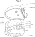
- FIG. 1 is a perspective view of an articulator 100 provided with the dental model 1.
- the articulator 100 includes a dental model 1 and a model support portion 101.
- the dental model 1 includes an upper dental model 1A and a lower dental model 1B.
- a tongue side where the tongue is present is defined as an oral side
- the opposite cheek and lip side are defined as an extra-oral side
- the molar teeth side and the front teeth side are defined as illustrated in the drawings.
- the side of the upper teeth is defined as an upper side
- the side of the lower teeth is defined as a lower side.
- the upper model support portion 101A includes an upper model fixing portion 111A, an upper holding portion 112A holding the rear portion of the upper model fixing portion 111A, and a pair of upper rearward extending portions 113A extending obliquely rearward and downward from the upper holding portion 112A.
- FIG. 2 is a diagram showing the upper model fixing portion 111A and the upper dental model 1A being detached from the upper model fixing portion 111A.
- the lower model fixing portion 111B is composed of a magnetic material, and a storage portion 114B having a shape corresponding to the shape of the lower surface of the lower dental model 1B is provided on the upper surface.
- a magnet is embedded in the lower dental model 1B.
- the lower dental model 1B is fit into the storage portion 114B of the lower model fixing portion 111B, and detachably held by a magnetic force.
- the plurality of insertion holes 20 are respectively provided at the top of the protruding portion of gum portion 12.
- the model teeth 50 are respectively inserted into the gum portions 12 through the insertion holes 20, respectively.
- a recess portion 18b continuing from a molar insertion hole 20b is formed on the oral side of the molar insertion hole 20b to which a detachable molar model tooth 50b is attached, and a molar teeth lid portion 13b is attached to the recess portion 18b.
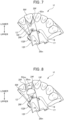
- FIG. 4 is a perspective view of the left molar teeth portion 1b, and shows a state in which the molar teeth lid portion 13b is open.
- FIG. 5 is a perspective view of the left molar teeth portion 1b, and shows a state in which the molar teeth lid portion 13b is opened, and the molar model tooth 50b is detached.
- FIG. 6 is perspective view of the left molar teeth portion 1b, and shows a state in which the molar teeth lid portion 13b is opened, and the molar model tooth 50b and the molar teeth lid portion 13b are detached.
- the molar teeth lid portion 13b is composed of the same material as the gum portion 12.
- the molar teeth lid portion 13b constitutes a part of the gum portion 12 in a closed state, and includes a surface 131b integral with the surface of the gum portion 12, and an inner surface 132b on the opposite side thereof.
- a portion of the inner circumferential surface which forms a root insertion hole 241 is formed on the inner surface 132b.
- the surface 131b of the molar teeth lid portion 13b in the closed state shown in FIG. 3 constitutes a part of the gum portion 12, the shape of the gum portion in an actual mouth is simulated, and the upper rim portion of the molar teeth lid portion 13b constitutes a part of the rim of the opening of the molar insertion hole 20b.
- shaft portions 17 extending in the dentition direction are formed to protrude, respectively.
- the inner surface of the recess portion 18b of gum portion 12 there is a groove portion 19 into which the shaft portion 17 is to be inserted.
- the groove portion 19 extends vertically from a tooth tip side of the model teeth 50 toward the flat surface 14, but does not penetrate the flat surface 14, and a bottom portion 191 is provided. Furthermore, a projection 192 is provided below the bottom portion 191 of the inner surface of the groove portion 19 (on the tooth tip side which is an upper side in FIG. 6 ).
- the shaft portion 17 is inserted into the groove portion 19 from the tooth tip side and slid to the flat surface 14 side.
- the shaft portion 17 passes over the projection 192, the shaft portion 17 is held in the space between the projection 192 and the bottom portion 191 in the groove portion 19.
- the shaft portion 17 is rotatably held in the space unless a force is applied to pass over the projection 192.
- the rotation of the shaft portion 17 in its space makes it possible for the molar teeth lid portion 13b to be swingable between the closed state of FIG. 3 and the open state of FIGS. 4 and 5 around the shaft portion 17.
- a screw insertion hole 25b of the transverse orientation which penetrates from the surface 131b side to the inner surface 132b side is provided in the molar teeth lid portion 13b.
- a threaded hole 26b is provided in a transverse orientation in the inner face facing the oral side at the recess portion 18b of gum portion 12.
- the crown portion 51b is a portion exposed from the molar insertion hole 20b in the gum portion 12 with the molar model tooth 50b fixed to the gum portion 12.
- the root portion 52b is a portion which is inserted into the interior of the molar insertion hole 20b and is covered by the gum portion 12 including the lid portion 13 with the molar model tooth 50b being fixed to the gum portion 12.
- the root portion 52b of the molar model tooth 50b comprises three root portions including a root portion 521 on the oral side, and a root portion 522 and a root portion 523 on the extra-oral side, and the root portion 521 on the oral side extends more laterally than the crown portion 51b. Extending laterally refers to a state in which the root portion 52 protrudes outward from the crown portion 51 when the model teeth 50 are viewed from the crown portion 51 side.
- a root insertion hole 242 and a root insertion hole 243 are provided, into which the root portion 522 and the root portion 523 on the extra-oral side are to be inserted.
- a part of the inner circumferential surface is provided which forms the root insertion hole 241 to which the root portion 521 on the oral side is to be inserted.
- the part of the inner circumferential surface which forms the root insertion hole 241 provided in the molar teeth lid portion 13b and the part of the inner circumferential surface which forms the root insertion hole 241 provided in the recess portion 18b together constitute the root insertion hole 241.
- an upper edge portion of the molar insertion hole 20b and an upper edge portion of the molar teeth lid portion 13b together define an edge portion of an opening of the molar insertion hole 20b.
- the opening of the molar insertion hole 20b of the embodiments is similar to that in an actual mouth, and is approximately the same shape as the outer circumference of the border between the crown portion 51b and the root portion 52b, which is the root of the crown portion 51b. Therefore, when the molar teeth lid portion 13b is being closed, the molar model tooth 50b having the root portion 521, which protrudes more outward than the crown portion 51b, cannot be attached to and detached from the gum portion 12 through the molar insertion hole 20b.
- the molar teeth lid portion 13b is opened as shown in FIG. 5 to open the recess portion 18b which is continuous from the molar insertion hole 20b.
- the root portion 522 and the root portion 523 of the molar model tooth 50b are inserted into the root insertion hole 242 and the root insertion hole 243, respectively, which are provided in the interior of the molar insertion hole 20b.
- One of the outer circumferential surface of the root portion 521 abuts the inner circumferential surface constituting a part of the root insertion hole 241 provided in the recess portion 18b. This leads to the state shown in FIG. 4 .
- a screw 27b is inserted in the transverse orientation into the screw insertion hole 25b, and screwed into the threaded hole 26b of the gum portion 12. This allows the root portion 521 of the molar model tooth 50b to be held by the molar teeth lid portion 13b, a result of which the molar model tooth 50b is fixed to the gum portion 12.
- the screw 27b When detaching the molar model tooth 50b from the gum portion 12, the screw 27b is rotated reversely contrary to when attaching the molar model tooth 50b as described above, and the molar model tooth 50b is detached from the threaded hole 26b and the screw insertion hole 25b. Furthermore, when the molar teeth lid portion 13b is opened, it is possible to detach from the gum portion 12 the molar model tooth 50b having the root portion 521, which protrudes more outward than the crown portion 51b.
- a recess portion 18f is also formed on the oral side of a front insertion hole 20f to which a detachable front model tooth 50f among the insertion holes 20 in the gum portion 12 is attached, and a front teeth lid portion 13f is attached to the recess portion 18f.
- the front model tooth 50f is inserted into the opened root insertion hole 24f with the front teeth lid portion 13f opened, as shown in FIG. 9 .
- the molar teeth lid portion 13b is provided on the oral side of one molar model tooth 50b among the model teeth 50 included in the left molar teeth portion 1b, and the molar model tooth 50b is attachable to and detachable from the gum portion 12.
- the front teeth lid portion 13f is provided on the oral side of the one front model tooth 50f among the model teeth 50 included in the front teeth portion 1f, and the front model tooth 50f is attachable to and detachable from the gum portion 12.
- lid portion 13 is provided in the upper dental model 1A.
- present disclosure is not limited thereto, and a lid portion may be provided in the lower dental model 1B.
- the lid portion 13 is configured to swing by the shaft portion 17 relative to the gum portion 12.
- the present disclosure is not limited thereto, and the lid portion 13 may not be engaged by the shaft portion 17, and may be, for example, separated upon detachment.
- the lid portion 13 is provided on the oral side of the insertion hole 20. According to this, the lid portion 13 is not visible when viewed from the extra-oral side. Therefore, it is superior in appearance. However, the present invention is not limited thereto, and the lid portion 13 may be provided on the extra-oral side of the insertion hole 20.
- the upper dental model 1A may be divided into three pieces.
- the present disclosure is not limited thereto.
- the number of divided pieces is not limited to three.
- the locations for the division are not limited to those in the embodiments.
- the lower dental model 1B may be divided.
Landscapes
- Health & Medical Sciences (AREA)
- Engineering & Computer Science (AREA)
- General Health & Medical Sciences (AREA)
- Oral & Maxillofacial Surgery (AREA)
- Epidemiology (AREA)
- Public Health (AREA)
- Physics & Mathematics (AREA)
- General Physics & Mathematics (AREA)
- Dentistry (AREA)
- Life Sciences & Earth Sciences (AREA)
- Animal Behavior & Ethology (AREA)
- Veterinary Medicine (AREA)
- Algebra (AREA)
- Mathematical Physics (AREA)
- Medical Informatics (AREA)
- Computational Mathematics (AREA)
- Chemical & Material Sciences (AREA)
- Mathematical Analysis (AREA)
- Mathematical Optimization (AREA)
- Medicinal Chemistry (AREA)
- Pure & Applied Mathematics (AREA)
- Business, Economics & Management (AREA)
- Educational Administration (AREA)
- Educational Technology (AREA)
- Theoretical Computer Science (AREA)
- Instructional Devices (AREA)
- Dental Prosthetics (AREA)
- Dental Tools And Instruments Or Auxiliary Dental Instruments (AREA)
Claims (8)
- Dentalmodell (1) umfassend:einen Gummiabschnitt (12), in welchem ein Einsetzloch (20b, 241) mit einer Öffnung, in welche ein Modellzahn (50) einzusetzen ist, vorgesehen ist; undeinen an einer oralen Seite oder einer extra-oralen Seite des Einsetzlochs (20) in dem Gummiabschnitt (12) vorgesehenen Klappenabschnitt (13b, 13f), wobei der Klappenabschnitt (13b, 13f) in einem geschlossenen Zustand einen Teil des Gummiabschnitts (12) bildet und in einem offenen Zustand wenigstens einen Teil eines Wurzelabschnitts des Modellzahns (50) freigibt, und wobei der Klappenabschnitt (13b, 13f) dazu ausgebildet ist, bezüglich des Gummiabschnitts (12) geöffnet und geschlossen zu werden,dadurch gekennzeichnet, dass dann, wenn der Klappenabschnitt (13b, 13f) geschlossen ist, der Rand der Öffnung des Einsetzlochs (20) durch an dem Gummiabschnitt (12) und dem Klappenabschnitt (13b, 13f) vorhandene Ränder gebildet ist, und beide Enden der Ränder des Gummiabschnitts (12) und des Klappenabschnitts (13b, 13f) sich zum Bilden einer Aussparung treffen, in welcher der Modellzahn (50) platziert ist, undder Klappenabschnitt (13b, 13f) bezüglich des Gummiabschnitts (12) zwischen dem geschlossenen Zustand und dem offenen Zustand schwenkbar gehalten ist.
- Dentalmodell (1) nach Anspruch 1, wobei der Klappenabschnitt (13b, 13f) an der oralen Seite oder der extra-oralen Seite des Gummiabschnitts (12) vorgesehen ist.
- Dentalmodell (1) nach Anspruch 1 oder 2, wobeidas Dentalmodell (1) den Modellzahn (50) umfasst,an einer Innenumfangsfläche des Einsetzlochs (20) eine Einsenkung (28in, 28ou) vorgesehen ist,ein vorstehender Abschnitt (53in, 53ou), welcher in Eingriff mit der Einsenkung (28in, 28ou) zu bringen ist, an einer Außenumfangsfläche des Wurzelabschnitts vorgesehen ist.
- Dentalmodell (1) nach einem der Ansprüche 1-3, wobei der Klappenabschnitt (13b, 13f) den geschlossenen Zustand durch Fixierung bezüglich des Gummiabschnitts (12) vermittels einer Schraube beibehält.
- Dentalmodell (1) nach einem der Ansprüche 1-4, wobei das Dentalmodell in eine Mehrzahl von Teilen aufteilbar ist.
- Dentalmodell (1) nach Anspruch 5, wobeidas Dentalmodell in wenigstens einen ersten Teil und einen zweiten Teil aufteilbar ist,eine Einsenkungsnut an einer dem zweiten Teil gegenüberliegenden Oberfläche des ersten Teils vorgesehen ist, undein in der Einsenkungsnut verschiebbarer Vorsprung an einer dem ersten Teil gegenüberliegenden Oberfläche des zweiten Teils vorgesehen ist.
- Dentalmodell (1) nach Anspruch 5 oder 6,wobei das Dentalmodell in wenigstens einen ersten Teil und einen zweiten Teil unterteilbar ist, undwobei der zweite Teil durch Magnetkraft an dem ersten Teil gehalten ist.
- Artikulator, umfassend:ein Dentalmodell (1) nach einem der Ansprüche 1-7; undeinen zum Tragen des Dentalmodells (1) ausgebildeten Modelltrageabschnitt.
Applications Claiming Priority (1)
| Application Number | Priority Date | Filing Date | Title |
|---|---|---|---|
| PCT/JP2020/029980 WO2022029922A1 (ja) | 2020-08-05 | 2020-08-05 | 歯科模型及び咬合器 |
Publications (4)
| Publication Number | Publication Date |
|---|---|
| EP4156150A1 EP4156150A1 (de) | 2023-03-29 |
| EP4156150A4 EP4156150A4 (de) | 2023-07-05 |
| EP4156150B1 true EP4156150B1 (de) | 2025-07-02 |
| EP4156150C0 EP4156150C0 (de) | 2025-07-02 |
Family
ID=80117758
Family Applications (1)
| Application Number | Title | Priority Date | Filing Date |
|---|---|---|---|
| EP20948597.8A Active EP4156150B1 (de) | 2020-08-05 | 2020-08-05 | Dentalmodell und artikulator |
Country Status (8)
| Country | Link |
|---|---|
| US (1) | US20220304783A1 (de) |
| EP (1) | EP4156150B1 (de) |
| JP (1) | JP7575746B2 (de) |
| CN (1) | CN116018630B (de) |
| CA (1) | CA3185369A1 (de) |
| ES (1) | ES3036797T3 (de) |
| MX (1) | MX2023001386A (de) |
| WO (1) | WO2022029922A1 (de) |
Families Citing this family (4)
| Publication number | Priority date | Publication date | Assignee | Title |
|---|---|---|---|---|
| USD1004780S1 (en) * | 2021-09-30 | 2023-11-14 | Shenzhen Youya Gifts Co., Ltd. | Dental model |
| EP4430592A4 (de) * | 2022-08-15 | 2025-11-05 | Createch Egitim Malzemeleri Sanayi Ve Ticaret Anonim Sirketi | Simulationsmodell für zahnärztliche ausbildung |
| KR20240178139A (ko) * | 2023-06-21 | 2024-12-30 | 비엔엘바이오테크 주식회사 | 치과치료 실습용 덴티폼 |
| WO2025147992A1 (zh) * | 2024-01-12 | 2025-07-17 | 株式会社日进 | 牙科切削实习用模型 |
Family Cites Families (17)
| Publication number | Priority date | Publication date | Assignee | Title |
|---|---|---|---|---|
| GB1131948A (en) * | 1966-07-01 | 1968-10-30 | Joe John Simmons | Dental appliance |
| JP3103569U (ja) * | 2004-02-23 | 2004-08-19 | 弘孝 戸田 | 咬合器用歯型模型固定具 |
| US6969258B1 (en) * | 2004-07-14 | 2005-11-29 | Farzad Shaygan | Dental model demonstrating tooth enamel loss and gum recession |
| JP2007328083A (ja) | 2006-06-07 | 2007-12-20 | Nippon Dental Univ | 歯列模型 |
| JP5041478B2 (ja) * | 2006-07-28 | 2012-10-03 | 国立大学法人 東京医科歯科大学 | 歯科模型用模型歯肉、歯科模型用模型歯肉部品、歯科模型用歯台、及び、歯科模型用キット |
| KR20080004984U (ko) * | 2007-04-24 | 2008-10-29 | 송 영 인터내셔널 컴퍼니 | 치아모형 고정틀 |
| JP2010131350A (ja) * | 2008-12-08 | 2010-06-17 | Toytec:Kk | 歩行玩具駆動モジュール |
| CN101866570B (zh) * | 2009-04-15 | 2011-08-24 | 日进齿科材料(昆山)有限公司 | 牙槽脓肿切开模型 |
| US8491305B2 (en) * | 2009-11-05 | 2013-07-23 | Yan Pogorelsky | System and method for aligning teeth |
| JPWO2012002487A1 (ja) * | 2010-07-01 | 2013-08-29 | 株式会社ニッシン | 歯科模型、支持台及びキット |
| JPWO2012002488A1 (ja) * | 2010-07-01 | 2013-08-29 | 株式会社ニッシン | 歯科模型及びキット |
| JP5778552B2 (ja) * | 2011-11-08 | 2015-09-16 | 株式会社モリタ製作所 | 実習模型装置 |
| JP2016004186A (ja) * | 2014-06-18 | 2016-01-12 | 株式会社ニッシン | 歯科模型 |
| US10096266B2 (en) * | 2015-06-09 | 2018-10-09 | Charles Q Lee | Dental training device |
| WO2020065847A1 (ja) * | 2018-09-27 | 2020-04-02 | 株式会社ニッシン | 咬合器 |
| AU2018435528B2 (en) * | 2018-09-27 | 2021-11-18 | Nissin Dental Products Inc. | Model teeth, model teeth base, and dental model |
| CN111192510B (zh) * | 2020-02-26 | 2024-09-06 | 日进教学器材(昆山)有限公司 | 实习用口腔模型 |
-
2020
- 2020-08-05 MX MX2023001386A patent/MX2023001386A/es unknown
- 2020-08-05 JP JP2021508330A patent/JP7575746B2/ja active Active
- 2020-08-05 CN CN202080104524.9A patent/CN116018630B/zh active Active
- 2020-08-05 WO PCT/JP2020/029980 patent/WO2022029922A1/ja not_active Ceased
- 2020-08-05 ES ES20948597T patent/ES3036797T3/es active Active
- 2020-08-05 CA CA3185369A patent/CA3185369A1/en active Pending
- 2020-08-05 EP EP20948597.8A patent/EP4156150B1/de active Active
- 2020-08-05 US US17/284,888 patent/US20220304783A1/en active Pending
Non-Patent Citations (1)
| Title |
|---|
| ANONYMOUS: "Anatomical Teaching Models - Plastic Human Dental Models - Lower Jaw with Diseased Teeth Model", 16 August 2022 (2022-08-16), pages 1 - 5, XP093138192, Retrieved from the Internet <URL:https://www.3bscientific.com/us/comprehensive-lower-jaw-model-left-half-with-diseased-teeth-nerves-vessels-glands-19-part-3b-smart-anatomy-1001250-ve290-3b-scientific,p_24_2247.html> [retrieved on 20240306] * |
Also Published As
| Publication number | Publication date |
|---|---|
| US20220304783A1 (en) | 2022-09-29 |
| EP4156150C0 (de) | 2025-07-02 |
| CN116018630B (zh) | 2025-09-16 |
| CA3185369A1 (en) | 2022-02-10 |
| EP4156150A1 (de) | 2023-03-29 |
| JP7575746B2 (ja) | 2024-10-30 |
| ES3036797T3 (en) | 2025-09-24 |
| EP4156150A4 (de) | 2023-07-05 |
| WO2022029922A1 (ja) | 2022-02-10 |
| JPWO2022029922A1 (de) | 2022-02-10 |
| MX2023001386A (es) | 2023-03-03 |
| CN116018630A (zh) | 2023-04-25 |
Similar Documents
| Publication | Publication Date | Title |
|---|---|---|
| EP4156150B1 (de) | Dentalmodell und artikulator | |
| JP3036751U (ja) | 人工歯及び歯冠修復材色調マッチング補助具 | |
| JP2013543411A (ja) | 義歯安定装置及び方法 | |
| JP5820679B2 (ja) | 歯科用印象用トレー | |
| US20040023185A1 (en) | Apparatus for improving the registration and articulation of dental stone replicas | |
| KR101117342B1 (ko) | 교합기 | |
| JP2016533824A (ja) | 口腔内基準物体 | |
| JP2022522120A (ja) | 義歯作成アセンブリ、方法、及び装置 | |
| US11464607B2 (en) | Model teeth, model teeth base, and dental model | |
| WO2022152707A1 (fr) | Ecarteur dentaire pour prises de vues autonomes, bouche fermée ou ouverte | |
| JP2019187489A (ja) | レーザー照射装置 | |
| JP6951808B2 (ja) | 咬合器 | |
| US12059318B2 (en) | Endodontic file holder | |
| US6139318A (en) | Color key | |
| CA2287086A1 (en) | Color key | |
| JPH0624854Y2 (ja) | 歯牙着脱可能な歯科実習用マネキン | |
| US7303391B1 (en) | Shade Aide—determination apparatus and method for determining the different shades to be added to a base shade in a porcelain crown | |
| KR20200144009A (ko) | 치과용 다기능 인상 트레이 | |
| CN118613855A (zh) | 牙科模型 | |
| EP4691419A1 (de) | Vorrichtung zur aufzeichnung der beziehung zwischen den kiefern zur herstellung einer digitalen zahnprothese | |
| JPH0738862B2 (ja) | 歯模型用トレー及び歯模型の離脱方法 | |
| JP3112180U (ja) | 疑似口唇片付顎模型 | |
| JP3134753U (ja) | 脱着の便利さを図るための義歯位置指定装置 | |
| JP2018079015A (ja) | 咬合印象用トレー | |
| KR20250012825A (ko) | 페이셜 스캐너를 이용한 디지털 틀니 제작용 악간 관계 기록 장치 |
Legal Events
| Date | Code | Title | Description |
|---|---|---|---|
| STAA | Information on the status of an ep patent application or granted ep patent |
Free format text: STATUS: THE INTERNATIONAL PUBLICATION HAS BEEN MADE |
|
| PUAI | Public reference made under article 153(3) epc to a published international application that has entered the european phase |
Free format text: ORIGINAL CODE: 0009012 |
|
| STAA | Information on the status of an ep patent application or granted ep patent |
Free format text: STATUS: REQUEST FOR EXAMINATION WAS MADE |
|
| 17P | Request for examination filed |
Effective date: 20221222 |
|
| AK | Designated contracting states |
Kind code of ref document: A1 Designated state(s): AL AT BE BG CH CY CZ DE DK EE ES FI FR GB GR HR HU IE IS IT LI LT LU LV MC MK MT NL NO PL PT RO RS SE SI SK SM TR |
|
| A4 | Supplementary search report drawn up and despatched |
Effective date: 20230602 |
|
| RIC1 | Information provided on ipc code assigned before grant |
Ipc: G09B 23/28 20060101ALI20230526BHEP Ipc: A61C 11/00 20060101ALI20230526BHEP Ipc: G09B 23/34 20060101AFI20230526BHEP |
|
| DAV | Request for validation of the european patent (deleted) | ||
| DAX | Request for extension of the european patent (deleted) | ||
| STAA | Information on the status of an ep patent application or granted ep patent |
Free format text: STATUS: EXAMINATION IS IN PROGRESS |
|
| 17Q | First examination report despatched |
Effective date: 20240313 |
|
| GRAP | Despatch of communication of intention to grant a patent |
Free format text: ORIGINAL CODE: EPIDOSNIGR1 |
|
| STAA | Information on the status of an ep patent application or granted ep patent |
Free format text: STATUS: GRANT OF PATENT IS INTENDED |
|
| INTG | Intention to grant announced |
Effective date: 20250211 |
|
| GRAS | Grant fee paid |
Free format text: ORIGINAL CODE: EPIDOSNIGR3 |
|
| GRAA | (expected) grant |
Free format text: ORIGINAL CODE: 0009210 |
|
| STAA | Information on the status of an ep patent application or granted ep patent |
Free format text: STATUS: THE PATENT HAS BEEN GRANTED |
|
| AK | Designated contracting states |
Kind code of ref document: B1 Designated state(s): AL AT BE BG CH CY CZ DE DK EE ES FI FR GB GR HR HU IE IS IT LI LT LU LV MC MK MT NL NO PL PT RO RS SE SI SK SM TR |
|
| REG | Reference to a national code |
Ref country code: GB Ref legal event code: FG4D |
|
| REG | Reference to a national code |
Ref country code: CH Ref legal event code: EP |
|
| REG | Reference to a national code |
Ref country code: DE Ref legal event code: R096 Ref document number: 602020054047 Country of ref document: DE |
|
| REG | Reference to a national code |
Ref country code: IE Ref legal event code: FG4D |
|
| U01 | Request for unitary effect filed |
Effective date: 20250801 |
|
| REG | Reference to a national code |
Ref country code: ES Ref legal event code: FG2A Ref document number: 3036797 Country of ref document: ES Kind code of ref document: T3 Effective date: 20250924 |
|
| U07 | Unitary effect registered |
Designated state(s): AT BE BG DE DK EE FI FR IT LT LU LV MT NL PT RO SE SI Effective date: 20250826 |
|
| PGFP | Annual fee paid to national office [announced via postgrant information from national office to epo] |
Ref country code: ES Payment date: 20250926 Year of fee payment: 6 |
|
| PGFP | Annual fee paid to national office [announced via postgrant information from national office to epo] |
Ref country code: TR Payment date: 20250922 Year of fee payment: 6 |
|
| PGFP | Annual fee paid to national office [announced via postgrant information from national office to epo] |
Ref country code: GB Payment date: 20250820 Year of fee payment: 6 |
|
| U20 | Renewal fee for the european patent with unitary effect paid |
Year of fee payment: 6 Effective date: 20250924 |
|
| PG25 | Lapsed in a contracting state [announced via postgrant information from national office to epo] |
Ref country code: IS Free format text: LAPSE BECAUSE OF FAILURE TO SUBMIT A TRANSLATION OF THE DESCRIPTION OR TO PAY THE FEE WITHIN THE PRESCRIBED TIME-LIMIT Effective date: 20251102 |
|
| PG25 | Lapsed in a contracting state [announced via postgrant information from national office to epo] |
Ref country code: NO Free format text: LAPSE BECAUSE OF FAILURE TO SUBMIT A TRANSLATION OF THE DESCRIPTION OR TO PAY THE FEE WITHIN THE PRESCRIBED TIME-LIMIT Effective date: 20251002 |
|
| PG25 | Lapsed in a contracting state [announced via postgrant information from national office to epo] |
Ref country code: HR Free format text: LAPSE BECAUSE OF FAILURE TO SUBMIT A TRANSLATION OF THE DESCRIPTION OR TO PAY THE FEE WITHIN THE PRESCRIBED TIME-LIMIT Effective date: 20250702 |
|
| PG25 | Lapsed in a contracting state [announced via postgrant information from national office to epo] |
Ref country code: GR Free format text: LAPSE BECAUSE OF FAILURE TO SUBMIT A TRANSLATION OF THE DESCRIPTION OR TO PAY THE FEE WITHIN THE PRESCRIBED TIME-LIMIT Effective date: 20251003 |
|
| PG25 | Lapsed in a contracting state [announced via postgrant information from national office to epo] |
Ref country code: CZ Free format text: LAPSE BECAUSE OF FAILURE TO SUBMIT A TRANSLATION OF THE DESCRIPTION OR TO PAY THE FEE WITHIN THE PRESCRIBED TIME-LIMIT Effective date: 20250702 |
|
| PG25 | Lapsed in a contracting state [announced via postgrant information from national office to epo] |
Ref country code: PL Free format text: LAPSE BECAUSE OF FAILURE TO SUBMIT A TRANSLATION OF THE DESCRIPTION OR TO PAY THE FEE WITHIN THE PRESCRIBED TIME-LIMIT Effective date: 20250702 |
|
| PG25 | Lapsed in a contracting state [announced via postgrant information from national office to epo] |
Ref country code: RS Free format text: LAPSE BECAUSE OF FAILURE TO SUBMIT A TRANSLATION OF THE DESCRIPTION OR TO PAY THE FEE WITHIN THE PRESCRIBED TIME-LIMIT Effective date: 20251002 |