EP4155619B1 - Warmlufterhitzer - Google Patents
Warmlufterhitzer Download PDFInfo
- Publication number
- EP4155619B1 EP4155619B1 EP22197122.9A EP22197122A EP4155619B1 EP 4155619 B1 EP4155619 B1 EP 4155619B1 EP 22197122 A EP22197122 A EP 22197122A EP 4155619 B1 EP4155619 B1 EP 4155619B1
- Authority
- EP
- European Patent Office
- Prior art keywords
- circuit board
- air duct
- driving circuit
- heater
- silicon
- Prior art date
- Legal status (The legal status is an assumption and is not a legal conclusion. Google has not performed a legal analysis and makes no representation as to the accuracy of the status listed.)
- Active
Links
Images


Classifications
-
- F—MECHANICAL ENGINEERING; LIGHTING; HEATING; WEAPONS; BLASTING
- F24—HEATING; RANGES; VENTILATING
- F24H—FLUID HEATERS, e.g. WATER OR AIR HEATERS, HAVING HEAT-GENERATING MEANS, e.g. HEAT PUMPS, IN GENERAL
- F24H3/00—Air heaters
- F24H3/02—Air heaters with forced circulation
- F24H3/022—Air heaters with forced circulation using electric energy supply
-
- F—MECHANICAL ENGINEERING; LIGHTING; HEATING; WEAPONS; BLASTING
- F24—HEATING; RANGES; VENTILATING
- F24H—FLUID HEATERS, e.g. WATER OR AIR HEATERS, HAVING HEAT-GENERATING MEANS, e.g. HEAT PUMPS, IN GENERAL
- F24H15/00—Control of fluid heaters
- F24H15/40—Control of fluid heaters characterised by the type of controllers
- F24H15/407—Control of fluid heaters characterised by the type of controllers using electrical switching, e.g. TRIAC
-
- F—MECHANICAL ENGINEERING; LIGHTING; HEATING; WEAPONS; BLASTING
- F24—HEATING; RANGES; VENTILATING
- F24H—FLUID HEATERS, e.g. WATER OR AIR HEATERS, HAVING HEAT-GENERATING MEANS, e.g. HEAT PUMPS, IN GENERAL
- F24H3/00—Air heaters
- F24H3/02—Air heaters with forced circulation
- F24H3/04—Air heaters with forced circulation the air being in direct contact with the heating medium, e.g. electric heating element
- F24H3/0405—Air heaters with forced circulation the air being in direct contact with the heating medium, e.g. electric heating element using electric energy supply, e.g. the heating medium being a resistive element; Heating by direct contact, i.e. with resistive elements, electrodes and fins being bonded together without additional element in-between
- F24H3/0411—Air heaters with forced circulation the air being in direct contact with the heating medium, e.g. electric heating element using electric energy supply, e.g. the heating medium being a resistive element; Heating by direct contact, i.e. with resistive elements, electrodes and fins being bonded together without additional element in-between for domestic or space-heating systems
-
- F—MECHANICAL ENGINEERING; LIGHTING; HEATING; WEAPONS; BLASTING
- F24—HEATING; RANGES; VENTILATING
- F24H—FLUID HEATERS, e.g. WATER OR AIR HEATERS, HAVING HEAT-GENERATING MEANS, e.g. HEAT PUMPS, IN GENERAL
- F24H9/00—Details
- F24H9/0052—Details for air heaters
- F24H9/0073—Arrangement or mounting of means for forcing the circulation of air
-
- F—MECHANICAL ENGINEERING; LIGHTING; HEATING; WEAPONS; BLASTING
- F24—HEATING; RANGES; VENTILATING
- F24H—FLUID HEATERS, e.g. WATER OR AIR HEATERS, HAVING HEAT-GENERATING MEANS, e.g. HEAT PUMPS, IN GENERAL
- F24H9/00—Details
- F24H9/20—Arrangement or mounting of control or safety devices
- F24H9/2064—Arrangement or mounting of control or safety devices for air heaters
- F24H9/2071—Arrangement or mounting of control or safety devices for air heaters using electrical energy supply
-
- H—ELECTRICITY
- H05—ELECTRIC TECHNIQUES NOT OTHERWISE PROVIDED FOR
- H05K—PRINTED CIRCUITS; CASINGS OR CONSTRUCTIONAL DETAILS OF ELECTRIC APPARATUS; MANUFACTURE OF ASSEMBLAGES OF ELECTRICAL COMPONENTS
- H05K1/00—Printed circuits
- H05K1/02—Details
- H05K1/0201—Thermal arrangements, e.g. for cooling, heating or preventing overheating
- H05K1/0203—Cooling of mounted components
-
- H—ELECTRICITY
- H05—ELECTRIC TECHNIQUES NOT OTHERWISE PROVIDED FOR
- H05K—PRINTED CIRCUITS; CASINGS OR CONSTRUCTIONAL DETAILS OF ELECTRIC APPARATUS; MANUFACTURE OF ASSEMBLAGES OF ELECTRICAL COMPONENTS
- H05K7/00—Constructional details common to different types of electric apparatus
- H05K7/20—Modifications to facilitate cooling, ventilating, or heating
- H05K7/20009—Modifications to facilitate cooling, ventilating, or heating using a gaseous coolant in electronic enclosures
- H05K7/20136—Forced ventilation, e.g. by fans
- H05K7/20145—Means for directing air flow, e.g. ducts, deflectors, plenum or guides
-
- A—HUMAN NECESSITIES
- A47—FURNITURE; DOMESTIC ARTICLES OR APPLIANCES; COFFEE MILLS; SPICE MILLS; SUCTION CLEANERS IN GENERAL
- A47K—SANITARY EQUIPMENT; ACCESSORIES THEREFOR, e.g. TOILET ACCESSORIES
- A47K13/00—Seats or covers for all kinds of closets
- A47K13/24—Parts or details not covered in, or of interest apart from, groups A47K13/02 - A47K13/22
- A47K13/30—Seats having provisions for heating, deodorising or the like, e.g. ventilating, noise-damping or cleaning devices
- A47K13/305—Seats with heating devices
-
- E—FIXED CONSTRUCTIONS
- E03—WATER SUPPLY; SEWERAGE
- E03D—WATER-CLOSETS OR URINALS WITH FLUSHING DEVICES; FLUSHING VALVES THEREFOR
- E03D9/00—Sanitary or other accessories for lavatories ; Devices for cleaning or disinfecting the toilet room or the toilet bowl; Devices for eliminating smells
- E03D9/04—Special arrangement or operation of ventilating devices
- E03D9/05—Special arrangement or operation of ventilating devices ventilating the bowl
- E03D9/052—Special arrangement or operation of ventilating devices ventilating the bowl using incorporated fans
-
- F—MECHANICAL ENGINEERING; LIGHTING; HEATING; WEAPONS; BLASTING
- F24—HEATING; RANGES; VENTILATING
- F24H—FLUID HEATERS, e.g. WATER OR AIR HEATERS, HAVING HEAT-GENERATING MEANS, e.g. HEAT PUMPS, IN GENERAL
- F24H2250/00—Electrical heat generating means
- F24H2250/02—Resistances
-
- Y—GENERAL TAGGING OF NEW TECHNOLOGICAL DEVELOPMENTS; GENERAL TAGGING OF CROSS-SECTIONAL TECHNOLOGIES SPANNING OVER SEVERAL SECTIONS OF THE IPC; TECHNICAL SUBJECTS COVERED BY FORMER USPC CROSS-REFERENCE ART COLLECTIONS [XRACs] AND DIGESTS
- Y02—TECHNOLOGIES OR APPLICATIONS FOR MITIGATION OR ADAPTATION AGAINST CLIMATE CHANGE
- Y02B—CLIMATE CHANGE MITIGATION TECHNOLOGIES RELATED TO BUILDINGS, e.g. HOUSING, HOUSE APPLIANCES OR RELATED END-USER APPLICATIONS
- Y02B10/00—Integration of renewable energy sources in buildings
- Y02B10/70—Hybrid systems, e.g. uninterruptible or back-up power supplies integrating renewable energies
Definitions
- This disclosure belongs to the technical field of intelligent toilets, and particularly relates to a driving part of a warm air heater and the warm air heater.
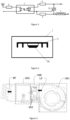
- At present intelligent toilet bowl is most configured with the warm air heater, and the drive circuit of warm air heater is as shown in fig. 1 , and drive circuit sets up on intelligent toilet bowl's main control circuit board under general condition, and heater block J sets up near the export in warm air heater wind channel, and drive circuit can drive the electric current change in the heater block J and change the temperature of heater block J, and cold wind is blown out from the export in wind channel after being heated by the heater block.
- the drive circuit comprises a thyristor TR, and the power of the warm air heater is higher, typically 150-300W, which requires that the drive circuit itself also has higher power, and the too high power may cause the temperature of the thyristor in the drive circuit to be too high and cause the problems of thermal breakdown failure of the thyristor, and the like.
- a large-area heat sink 2 is disposed on a PCB 1 on which the thyristor is disposed, so as to improve the heat dissipation efficiency and solve the problem of heat dissipation of the thyristor.
- the driving circuit is disposed on the main control circuit board (i.e., the PCB board 1 needs to be disposed on the main control circuit board), the space of the installation position of the main control circuit board is limited, it is difficult to dispose a large-area heat sink, and even if the heat dissipation of the thyristor is improved by disposing the large-area heat sink, the dissipated heat is also collected in the installation space of the main control circuit board, which leads to the overall increase of the internal temperature of the space, and may adversely affect the working performance of the main control circuit board.
- EP3096587 discloses an electrical heating device, in particular for a motor vehicle, with at least one heating element and with at least one control device with a housing, with at least one printed circuit board, with a first printed circuit board section and a second printed circuit board section, and with at least one first plug-in device and with at least one second plug-in device, the two plug-in devices for connecting the at least one heating element to the control device, the housing only partially accommodating the at least one printed circuit board, the first printed circuit board section being arranged in the housing and the second printed circuit board section emerging from the housing s and the at least one first plug-in device is connected to the second printed circuit board section and the at least one second plug-in device is connected to the heating element.
- WO 03/086018 A1 discloses an electric heating device comprising an electric radiator heating the air which penetrates said radiator.
- the radiator is provided with a housing, at least one resistive element that is mounted in the housing and is formed by at least one zigzag-shaped metal ribbon which is disposed such that said metal ribbon is directly exposed to the air penetrating the housing, and a circuit controlling the electric power supplied to the resistive element(s) which is/are connected to a source of power.
- the electric radiator comprises a set of individual heating modules which are disposed parallel to each other inside the housing and in such a way that said heating modules are directly exposed to the air penetrating the housing.
- Each heating module is provided with a folded or undular metal ribbon and an electronic interrupter which is controlled by the control circuit selectively blocking the supply of electric power to the metal ribbon.
- FR 2855933 A1 discloses a device that has a case circulated with air to be heated and delimiting a heat space that comprises of electrical heating modules. Each heating module has two metallic ribbons and resistive units with positive temperature coefficient.
- the case has supply compartments for housing supply modules. The supply compartments constitute an active zone in the delimited heat space.
- DE102011005733 discloses heat-dissipating fins are provided on a top surface of a case in which a plurality of electronic control circuits for controlling a plurality of on-vehicle components are housed.
- the heat-dissipating fins extend into an air passage formed by an air-intake-side duct of an air conditioner on an upstream side of a blower device.
- Heat generating elements of the plurality of electronic control circuits are fixed to a heat dissipating surface which is an inner surface of the case adjacent to the top surface on which the heat dissipating fins are provided.
- the disclosure aims to solve the technical problem that a thyristor in a driving circuit of the existing warm air heater has poor heat dissipation effect and provides a driving part of the warm air heater and the warm air heater.
- the technical scheme provided by the utility model at least has the following beneficial effects: the drive circuit board with driver part sets up in the wind channel alone, is located the upper reaches of heater block or with heater block looks parallel and level, therefore the cold wind that the fan blew out can directly cool down the silicon controlled rectifier element in the drive circuit board.
- the driving part of the utility model utilizes the fan to cool the silicon-controlled element, can realize good cooling effect without increasing large-area radiating fins, and reduces the cost of the driving part.
- the present invention provides a heater according to claim 1 and shown in fig. 3 to 4 .
- the circuit principle of the driving part can refer to fig. 1 , wherein the heating part J is disposed near the outlet of the air duct 300, and the electric connection between the driving circuit board and the heating part J is unchanged.
- a first mounting position 302 for disposing a driving circuit board disposed at the first mounting position 302 in the wind tunnel 300 of the warm air heater and a second mounting position 303 for disposing a heating member J may be included in the wind tunnel 300.
- the driving circuit board is located at the upstream of the heating component J or is flush with the heating component J, wherein the upstream or flush is based on the airflow direction in the air duct 300.
- the relationship between the fan 301, the first mounting position 302 and the second mounting position 303 can be determined by combining fig. 4 and fig. 6 .
- fan 301 blows out cold wind LF back, and cold wind LF passes through first mounted position 302 earlier and passes through second mounted position 303 again, becomes hot-blast RF after being heated by heating member J, so thyristor TR of first mounted position 302 department can dispel the heat under the effect of cold wind LF, and has spectacular radiating effect, and the heat that thyristor TR effuses can be blown out along wind channel 300 in addition, cannot be detained in thyristor TR's mounted position.
- the cold wind LF simultaneously passes through the first mounting position 302 and the second mounting position 303, and is heated by the heating part J when passing through the second mounting position 303 and becomes hot wind RF, so the thyristor TR at the first mounting position 302 still is acted on by the cold wind LF, can dispel the heat under the effect of the cold wind LF, and the heat that the thyristor TR dispels can be blown out along the wind channel 300, cannot be detained in the mounting position of thyristor TR.
- the driving circuit board including the thyristor is disposed in the air duct 300, and the driving circuit board is disposed at the upstream of the heating component or flush with the heating component, so that the cold air blown by the fan 301 can directly cool the thyristor.
- the drive unit in this scheme utilizes fan 301's cold wind to cool down the thyristor, need not to increase the large tracts of land fin and also can realize very good cooling effect, has reduced drive unit's cost, in addition, because drive circuit board need not to set up on main control circuit board, also does benefit to main control circuit board installation space's utilization more, can realize the miniaturization of main control part.
- the structure of the warm air heater shown in the above drawings is a schematic view from an external perspective
- the driving circuit board described in the embodiments of the present invention is disposed inside the air duct 300
- the structure of the air duct 300 itself is well known to those skilled in the art
- the driving circuit board only needs to be disposed at an appropriate position at an upstream or flush position of the heating component J, and is not described in detail in the drawings of the present invention.
- the thyristor when the driving circuit board is disposed on the inner wall of the air duct 300, the thyristor is disposed in the middle of the air duct 300, that is, in the air flow channel. Because the area of the silicon-controlled element is very small, the silicon-controlled element does not have great influence on the wind speed even if the silicon-controlled element is arranged in the airflow passage, and the silicon-controlled element can be cooled better in the airflow passage.
- the driving part further includes a fixing member, which may be a screw, for fixing the driving circuit board to the inner wall of the air duct.
- the driving part further comprises a sealing adhesive layer, the sealing adhesive layer is arranged on the surface of the driving circuit board and between the driving circuit board and the inner wall of the air channel, the driving circuit board can be arranged at the existing sinking position in the air channel at the moment, the sealing adhesive layer can be obtained after the sealing adhesive is poured into the sinking position, the sealing adhesive layer can be rubber, ethylene propylene diene monomer rubber and the like, and the sealing adhesive layer can not only realize the fixation of the driving circuit board, but also prevent the driving circuit board from being affected by damp.
- the silicon-controlled element is provided with a heat sink.
- the area of the heat sink does not need to be too large, and only needs to be matched with the surface area of the thyristor.
- the structure of setting up the fin can improve the radiating efficiency of silicon-controlled element, inside wind channel 300 moreover, has the space bigger than main control circuit board mounted position, cannot bring any inconvenience for setting up the fin.
- Some embodiments of the present invention further provide a warm air heater, which includes a fan 301, an air duct 300, a heating component and the driving component described in any of the above embodiments; the heating component and the driving circuit board in the driving component are both arranged in the air duct 300, and the position of the driving circuit board in the air duct 300 is located at the upstream of the heating component or is flush with the heating component, wherein the upstream or flush is based on the direction of the air flow in the air duct.
- a warm air heater which includes a fan 301, an air duct 300, a heating component and the driving component described in any of the above embodiments; the heating component and the driving circuit board in the driving component are both arranged in the air duct 300, and the position of the driving circuit board in the air duct 300 is located at the upstream of the heating component or is flush with the heating component, wherein the upstream or flush is based on the direction of the air flow in the air duct.
- a large amount of cold air in the air duct 300 plays a role in cooling and dissipating the silicon controlled rectifier on the driving circuit board, which is beneficial to fully utilizing the internal space of the air duct 300, and solves the problem that the occupied internal space is too large due to the large-area heat dissipation fins additionally arranged at the installation position of the main control circuit board in the prior art, and this scheme is beneficial to the modular design of the warm air heating control device, and reduces the design cost.
- the heating component includes but is not limited to a heating coil, a heating wire or a ceramic heater, so that the product can adapt to different air duct shapes and structures and has stronger adaptability.
- an accommodating cavity is formed in the air duct 300 at a position corresponding to the driving circuit board, and the driving circuit board is disposed in the accommodating cavity. That is, the casing of the air duct 300 is designed to be protruded at the position where the driving circuit board is installed, so that the driving circuit board is installed at the sinking portion, and the driving circuit board is conveniently subjected to waterproof and moisture proof glue filling treatment.
- warm braw heater still includes: the sealing adhesive layer is obtained by pouring colloid into the accommodating cavity.
- the sealant layer has the effects of preventing corrosion and isolating damp gas and is also beneficial to fixing the driving circuit board.
- the air duct 300 is provided with a lead through hole, and the lead through hole is used for a signal line, a power line and other leads to pass through.
- the driving circuit board needs to receive signals transmitted on the main control circuit board, the driving circuit board needs to be connected with the main control circuit board through signal lines, power lines and the like.
- the wire connection may be implemented from the outside of the air duct 300, and the signal line and the strong current line only need to pass through the wire through hole.
- the air duct 300 of the heater includes a first assembly 30A and a second assembly 30B, and a locking groove and a tooth are formed at a connection position of the first assembly 30A and the second assembly 30B, respectively, and the tooth is connected to the locking groove in a matching manner.
- the joint portion 30C is assembled together by the first assembly 30A and the second assembly 30B in a manner similar to a bayonet fitting, so that the obtained air duct 300 has extremely strong sealing performance, and if water drops exist on the outer wall of the air duct 300, even if the water drops slide to the joint portion 30C, the water drops cannot invade into the air duct 300, so that electronic components inside the air duct 300 can be well protected.
Landscapes
- Engineering & Computer Science (AREA)
- Physics & Mathematics (AREA)
- Thermal Sciences (AREA)
- Chemical & Material Sciences (AREA)
- Combustion & Propulsion (AREA)
- Mechanical Engineering (AREA)
- General Engineering & Computer Science (AREA)
- Microelectronics & Electronic Packaging (AREA)
- Cooling Or The Like Of Electrical Apparatus (AREA)
- Direct Air Heating By Heater Or Combustion Gas (AREA)
Claims (13)
- Erhitzer für Warmluft, umfassend:einen Lüfter (301),einen Luftkanal (300),einen im Luftkanal (300) angeordneten Heizteil,einen Antriebsteil, umfassend:
eine mit einem siliziumgesteuerten Element bereitgestellte Antriebsleiterplatte, wobei die Antriebsleiterplatte und das siliziumgesteuerte Element im Luftkanal (300) stromaufwärts des Heizteils in Bezug zur Richtung des Luftstroms im Luftkanal (300) eingerichtet sind. - Erhitzer nach Anspruch 1, wobei:
die Antriebsleiterplatte an einer Innenwand des Luftkanals (300) eingerichtet ist, wobei das siliziumgesteuerte Element an einem Luftstromdurchgang des Luftkanals (300) positioniert ist. - Erhitzer nach Anspruch 1 oder Anspruch 2, weiter umfassend:
ein Befestigungsstück, das zum Befestigen der Antriebsleiterplatte an der Innenwand des Luftkanals (300) verwendet wird. - Erhitzer nach Anspruch 1, Anspruch 2 oder Anspruch 3, weiter umfassend:
eine abdichtende Klebeschicht, die auf der Oberfläche der Antriebsleiterplatte und zwischen der Antriebsleiterplatte und der Innenwand des Luftkanals (300) eingerichtet ist. - Erhitzer nach einem der Ansprüche 1 bis 4, wobei das siliziumgesteuerte Element mit einer wärmeabstrahlenden Rippe bereitgestellt ist.
- Warmlufterhitzer nach Anspruch 5, wobei die wärmeabstrahlende Rippe eine Größe aufweist, die mit einem Oberflächenbereich des siliziumgesteuerten Elements übereinstimmt.
- Erhitzer nach einem vorstehenden Anspruch, wobei:
der Heizteil eine Heizspirale, einen Heizdraht oder einen Keramikerhitzer beinhaltet. - Erhitzer nach einem vorstehenden Anspruch, wobei:
ein Aufnahmehohlraum in dem Luftkanal (300) an einer Position gebildet ist, die der Antriebsleiterplatte entspricht, und die Antriebsleiterplatte in dem Aufnahmehohlraum eingerichtet ist. - Erhitzer nach Anspruch 8, weiter umfassend:
eine abdichtende Klebeschicht, die durch Gießen von Kolloid in den Aufnahmehohlraum gebildet wird. - Warmlufterhitzer nach einem vorstehenden Anspruch, wobei:der Luftkanal (300) eine erste Unterbaugruppe (30A) und eine zweite Unterbaugruppe (30B) beinhaltet;die erste Unterbaugruppe (30A) eine Verriegelungsnut umfasst und die zweite Unterbaugruppe (30B) einen Zahn umfasst; undder Zahn mit der Verriegelungsnut in Eingriff steht.
- Warmlufterhitzer nach einem vorstehenden Anspruch, wobei:der Luftkanal (300) mindestens ein Durchgangsloch umfasst, das konfiguriert ist, um es einem Draht zu ermöglichen, hindurchzugehen; undwobei der Draht konfiguriert ist, um Signale zwischen der Antriebsleiterplatte und einer Hauptsteuerungsplatine zu übertragen.
- Warmlufterhitzer nach einem vorstehenden Anspruch, wobei:die Antriebsleiterplatte konfiguriert ist, um stromabwärts des Lüfters (301) angeordnet zu werden; undder Lüfter (301) konfiguriert ist, um kalten Wind zum Abkühlen des auf der Antriebsleiterplatte angeordneten siliziumgesteuerten Elements auszuströmen.
- Warmlufterhitzer nach einem vorstehenden Anspruch, wobei:
der vom Lüfter (301) ausgeblasene kalte Wind sich entlang des Luftkanals (300) bewegt, um zuerst das siliziumgesteuerte Element abzukühlen und um dann vom Heizteil erhitzt zu werden, um zu einem warmen Wind zu werden.
Applications Claiming Priority (1)
| Application Number | Priority Date | Filing Date | Title |
|---|---|---|---|
| CN202122324680.0U CN215930157U (zh) | 2021-09-24 | 2021-09-24 | 一种暖风加热器的驱动部件及暖风加热器 |
Publications (2)
| Publication Number | Publication Date |
|---|---|
| EP4155619A1 EP4155619A1 (de) | 2023-03-29 |
| EP4155619B1 true EP4155619B1 (de) | 2024-10-30 |
Family
ID=80414282
Family Applications (1)
| Application Number | Title | Priority Date | Filing Date |
|---|---|---|---|
| EP22197122.9A Active EP4155619B1 (de) | 2021-09-24 | 2022-09-22 | Warmlufterhitzer |
Country Status (3)
| Country | Link |
|---|---|
| US (1) | US20230097894A1 (de) |
| EP (1) | EP4155619B1 (de) |
| CN (1) | CN215930157U (de) |
Family Cites Families (35)
| Publication number | Priority date | Publication date | Assignee | Title |
|---|---|---|---|---|
| US3571663A (en) * | 1969-01-08 | 1971-03-23 | Chemetron Corp | Releasable clamp assembly for a solid state circuit element |
| US3955122A (en) * | 1974-02-26 | 1976-05-04 | Armor Elevator Company, Inc. | Heat sink mounting for controlled rectifiers |
| US4088869A (en) * | 1975-04-28 | 1978-05-09 | General Electric Company | Temperature limiting circuit for electric hair dryers |
| US4196343A (en) * | 1978-03-02 | 1980-04-01 | C.A.H., Inc. | Hair dryer |
| US4876435A (en) * | 1988-01-13 | 1989-10-24 | Hawkins F Jr | Sanitary hand dryer |
| GB9024419D0 (en) * | 1990-11-09 | 1991-01-02 | Ist Lab Ltd | Heating apparatus |
| US5146695A (en) * | 1990-11-21 | 1992-09-15 | Yang Tai Her | Hand or hair dryer |
| US5568691A (en) * | 1992-09-22 | 1996-10-29 | Secajo, Ltd. | Hair dryer apparatus adapted for multi-functional usage |
| US5612849A (en) * | 1994-12-30 | 1997-03-18 | Conair Corporation | Static eliminator for hair dryers |
| US5805767A (en) * | 1996-01-16 | 1998-09-08 | Jouas; Gary | Electronically-controlled heater |
| US5884008A (en) * | 1997-12-08 | 1999-03-16 | Goldberg; Sherry P | Portable hair dryer for use in a vehicle with handle switch responsive to pivoting and vehicle battery voltage indicator |
| US6144013A (en) * | 1999-07-01 | 2000-11-07 | International Business Machines Corporation | Local humidity control system for low temperature electronic module |
| US6987250B2 (en) * | 2000-04-28 | 2006-01-17 | The Holmes Group, Inc. | Control circuit for kitchen appliances |
| US6732449B2 (en) * | 2000-09-15 | 2004-05-11 | Walter Evanyk | Dryer/blower appliance with efficient waste heat dissipation |
| US6640049B1 (en) * | 2000-11-22 | 2003-10-28 | Sharper Image Corporation | Ion emitting hot air blower |
| FR2838599B1 (fr) * | 2002-04-11 | 2004-08-06 | Valeo Climatisation | Dispositif de chauffage electrique, notamment pour appareil de chauffage et ou climatisation de vehicule |
| US6784775B2 (en) * | 2002-08-29 | 2004-08-31 | Ljm Associates, Inc. | Proximity safety switch suitable for use in a hair dryer for disabling operation |
| FR2855933B1 (fr) * | 2003-06-06 | 2006-06-09 | Valeo Climatisation | Dispositif de chauffage electrique, notamment pour un vehicule automobile |
| US7203416B2 (en) * | 2003-11-21 | 2007-04-10 | Broan-Nutone Llc | Ventilating and heating apparatus with heater shielded by tapered discharge duct |
| US7012223B2 (en) * | 2003-11-25 | 2006-03-14 | National Environmental Products, Ltd. | Forced-air heater control system and method |
| JP2005168268A (ja) * | 2003-12-05 | 2005-06-23 | Asmo Co Ltd | モータの駆動回路装置、及びモータ |
| AU2007318043B2 (en) * | 2006-11-01 | 2012-08-23 | Acepower Logistics Inc. | Infrared room heater system |
| US8285127B2 (en) * | 2007-09-05 | 2012-10-09 | Tpi Corporation | In-line duct supplemental heating and cooling device and method |
| JP4638923B2 (ja) * | 2008-03-31 | 2011-02-23 | 日立オートモティブシステムズ株式会社 | 制御装置 |
| US8249438B2 (en) * | 2008-10-01 | 2012-08-21 | Tek Maker Corporation | Multi-setting circuits for the portable dryer |
| EP2315493B1 (de) * | 2009-10-21 | 2017-05-10 | Mahle Behr France Rouffach S.A.S | Heizeinrichtung insbesondere für eine Kraftfahrzeugklimaanlage |
| JP5392213B2 (ja) * | 2010-03-23 | 2014-01-22 | 株式会社デンソー | 電子制御装置およびその冷却装置 |
| IT1399252B1 (it) * | 2010-04-02 | 2013-04-11 | Irca Spa | Riscaldatore d'aria elettrico, in particolare per elettrodomestici |
| CN202126082U (zh) * | 2011-05-25 | 2012-01-25 | 上海科勒电子科技有限公司 | 一种应用于厨卫产品的瞬时加热器 |
| US20140190034A1 (en) * | 2013-01-10 | 2014-07-10 | William F. Farrall, Sr. | Heater and dehumidifier for game calls |
| EP2863143B1 (de) * | 2013-10-21 | 2019-02-20 | Mahle Behr France Rouffach S.A.S | Heizvorrichtung |
| EP3096587B1 (de) * | 2015-05-20 | 2019-07-17 | MAHLE International GmbH | Elektrische heizvorrichtung |
| JP2018091247A (ja) * | 2016-12-05 | 2018-06-14 | 日本電産コパル電子株式会社 | 送風機 |
| US20180172266A1 (en) * | 2016-12-21 | 2018-06-21 | Electric Horsepower Inc. | Electric resistance heater system and light tower |
| US10575707B2 (en) * | 2017-08-09 | 2020-03-03 | Haier Us Appliance Solutions, Inc. | Dishwasher appliances and user interfaces |
-
2021
- 2021-09-24 CN CN202122324680.0U patent/CN215930157U/zh active Active
-
2022
- 2022-09-22 EP EP22197122.9A patent/EP4155619B1/de active Active
- 2022-09-23 US US17/951,354 patent/US20230097894A1/en active Pending
Also Published As
| Publication number | Publication date |
|---|---|
| US20230097894A1 (en) | 2023-03-30 |
| CN215930157U (zh) | 2022-03-01 |
| EP4155619A1 (de) | 2023-03-29 |
Similar Documents
| Publication | Publication Date | Title |
|---|---|---|
| ES2382007T3 (es) | Inversor | |
| EP4017231B1 (de) | Verbundzahnstrahler und kommunikationsbasisstation | |
| CN203279443U (zh) | 电控箱及具有该电控箱的空调器 | |
| CN211656631U (zh) | 电机驱动器及电动装置 | |
| US20030142481A1 (en) | Intake module having integrated ECU | |
| WO2025130419A1 (zh) | 控制器以及车辆 | |
| CN218977110U (zh) | 电子装置、电子设备和电子系统 | |
| EP4155619B1 (de) | Warmlufterhitzer | |
| CN107482856B (zh) | 汽车空调电机 | |
| CN111800989B (zh) | 控制器及应用其的空调 | |
| CN219063703U (zh) | 空调室内机以及空调器 | |
| WO2020051763A1 (zh) | 一种适用于充电桩模块的隔离式散热结构及其散热方法 | |
| CN208425101U (zh) | 一种适用于充电桩模块的隔离式散热结构 | |
| CN218040390U (zh) | 一种方便散热的综合布线柜 | |
| CN215637643U (zh) | 电控盒、空调室外机和空调器 | |
| CN210405072U (zh) | 一种定向散热的变频器 | |
| CN101151585A (zh) | 冷却装置 | |
| CN214256985U (zh) | 散热组件、电控箱及空调 | |
| CN212487047U (zh) | 控制器及应用其的空调 | |
| KR102011670B1 (ko) | 차량용 히터 | |
| CN211739471U (zh) | 屋顶机的风机装置及具有其的屋顶机 | |
| CN220087770U (zh) | 电控箱组件及空调器 | |
| CN222073712U (zh) | 一种用于机柜的散热模块和机柜 | |
| CN211959887U (zh) | 一种防护散热功率设备 | |
| JP2004106614A (ja) | 車両用空調機および空調機用パワーモジュール |
Legal Events
| Date | Code | Title | Description |
|---|---|---|---|
| PUAI | Public reference made under article 153(3) epc to a published international application that has entered the european phase |
Free format text: ORIGINAL CODE: 0009012 |
|
| STAA | Information on the status of an ep patent application or granted ep patent |
Free format text: STATUS: THE APPLICATION HAS BEEN PUBLISHED |
|
| AK | Designated contracting states |
Kind code of ref document: A1 Designated state(s): AL AT BE BG CH CY CZ DE DK EE ES FI FR GB GR HR HU IE IS IT LI LT LU LV MC MK MT NL NO PL PT RO RS SE SI SK SM TR |
|
| STAA | Information on the status of an ep patent application or granted ep patent |
Free format text: STATUS: REQUEST FOR EXAMINATION WAS MADE |
|
| 17P | Request for examination filed |
Effective date: 20230823 |
|
| RBV | Designated contracting states (corrected) |
Designated state(s): AL AT BE BG CH CY CZ DE DK EE ES FI FR GB GR HR HU IE IS IT LI LT LU LV MC MK MT NL NO PL PT RO RS SE SI SK SM TR |
|
| GRAP | Despatch of communication of intention to grant a patent |
Free format text: ORIGINAL CODE: EPIDOSNIGR1 |
|
| STAA | Information on the status of an ep patent application or granted ep patent |
Free format text: STATUS: GRANT OF PATENT IS INTENDED |
|
| RIC1 | Information provided on ipc code assigned before grant |
Ipc: A47K 13/30 20060101ALI20240506BHEP Ipc: E03D 9/04 20060101ALI20240506BHEP Ipc: A47K 10/48 20060101ALI20240506BHEP Ipc: F24H 9/20 20220101ALI20240506BHEP Ipc: F24H 3/04 20220101ALI20240506BHEP Ipc: F24H 15/407 20220101ALI20240506BHEP Ipc: F24H 9/00 20220101ALI20240506BHEP Ipc: F24H 3/02 20220101AFI20240506BHEP |
|
| INTG | Intention to grant announced |
Effective date: 20240604 |
|
| GRAS | Grant fee paid |
Free format text: ORIGINAL CODE: EPIDOSNIGR3 |
|
| GRAA | (expected) grant |
Free format text: ORIGINAL CODE: 0009210 |
|
| STAA | Information on the status of an ep patent application or granted ep patent |
Free format text: STATUS: THE PATENT HAS BEEN GRANTED |
|
| AK | Designated contracting states |
Kind code of ref document: B1 Designated state(s): AL AT BE BG CH CY CZ DE DK EE ES FI FR GB GR HR HU IE IS IT LI LT LU LV MC MK MT NL NO PL PT RO RS SE SI SK SM TR |
|
| REG | Reference to a national code |
Ref country code: GB Ref legal event code: FG4D |
|
| REG | Reference to a national code |
Ref country code: CH Ref legal event code: EP |
|
| REG | Reference to a national code |
Ref country code: IE Ref legal event code: FG4D |
|
| REG | Reference to a national code |
Ref country code: DE Ref legal event code: R096 Ref document number: 602022007219 Country of ref document: DE |
|
| REG | Reference to a national code |
Ref country code: LT Ref legal event code: MG9D |
|
| REG | Reference to a national code |
Ref country code: NL Ref legal event code: MP Effective date: 20241030 |
|
| PG25 | Lapsed in a contracting state [announced via postgrant information from national office to epo] |
Ref country code: HR Free format text: LAPSE BECAUSE OF FAILURE TO SUBMIT A TRANSLATION OF THE DESCRIPTION OR TO PAY THE FEE WITHIN THE PRESCRIBED TIME-LIMIT Effective date: 20241030 Ref country code: IS Free format text: LAPSE BECAUSE OF FAILURE TO SUBMIT A TRANSLATION OF THE DESCRIPTION OR TO PAY THE FEE WITHIN THE PRESCRIBED TIME-LIMIT Effective date: 20250228 Ref country code: PT Free format text: LAPSE BECAUSE OF FAILURE TO SUBMIT A TRANSLATION OF THE DESCRIPTION OR TO PAY THE FEE WITHIN THE PRESCRIBED TIME-LIMIT Effective date: 20250228 |
|
| PG25 | Lapsed in a contracting state [announced via postgrant information from national office to epo] |
Ref country code: FI Free format text: LAPSE BECAUSE OF FAILURE TO SUBMIT A TRANSLATION OF THE DESCRIPTION OR TO PAY THE FEE WITHIN THE PRESCRIBED TIME-LIMIT Effective date: 20241030 Ref country code: NL Free format text: LAPSE BECAUSE OF FAILURE TO SUBMIT A TRANSLATION OF THE DESCRIPTION OR TO PAY THE FEE WITHIN THE PRESCRIBED TIME-LIMIT Effective date: 20241030 |
|
| REG | Reference to a national code |
Ref country code: AT Ref legal event code: MK05 Ref document number: 1737209 Country of ref document: AT Kind code of ref document: T Effective date: 20241030 |
|
| PG25 | Lapsed in a contracting state [announced via postgrant information from national office to epo] |
Ref country code: BG Free format text: LAPSE BECAUSE OF FAILURE TO SUBMIT A TRANSLATION OF THE DESCRIPTION OR TO PAY THE FEE WITHIN THE PRESCRIBED TIME-LIMIT Effective date: 20241030 |
|
| PG25 | Lapsed in a contracting state [announced via postgrant information from national office to epo] |
Ref country code: ES Free format text: LAPSE BECAUSE OF FAILURE TO SUBMIT A TRANSLATION OF THE DESCRIPTION OR TO PAY THE FEE WITHIN THE PRESCRIBED TIME-LIMIT Effective date: 20241030 |
|
| PG25 | Lapsed in a contracting state [announced via postgrant information from national office to epo] |
Ref country code: NO Free format text: LAPSE BECAUSE OF FAILURE TO SUBMIT A TRANSLATION OF THE DESCRIPTION OR TO PAY THE FEE WITHIN THE PRESCRIBED TIME-LIMIT Effective date: 20250130 |
|
| PG25 | Lapsed in a contracting state [announced via postgrant information from national office to epo] |
Ref country code: GR Free format text: LAPSE BECAUSE OF FAILURE TO SUBMIT A TRANSLATION OF THE DESCRIPTION OR TO PAY THE FEE WITHIN THE PRESCRIBED TIME-LIMIT Effective date: 20250131 Ref country code: LV Free format text: LAPSE BECAUSE OF FAILURE TO SUBMIT A TRANSLATION OF THE DESCRIPTION OR TO PAY THE FEE WITHIN THE PRESCRIBED TIME-LIMIT Effective date: 20241030 Ref country code: AT Free format text: LAPSE BECAUSE OF FAILURE TO SUBMIT A TRANSLATION OF THE DESCRIPTION OR TO PAY THE FEE WITHIN THE PRESCRIBED TIME-LIMIT Effective date: 20241030 |
|
| PG25 | Lapsed in a contracting state [announced via postgrant information from national office to epo] |
Ref country code: PL Free format text: LAPSE BECAUSE OF FAILURE TO SUBMIT A TRANSLATION OF THE DESCRIPTION OR TO PAY THE FEE WITHIN THE PRESCRIBED TIME-LIMIT Effective date: 20241030 |
|
| PG25 | Lapsed in a contracting state [announced via postgrant information from national office to epo] |
Ref country code: RS Free format text: LAPSE BECAUSE OF FAILURE TO SUBMIT A TRANSLATION OF THE DESCRIPTION OR TO PAY THE FEE WITHIN THE PRESCRIBED TIME-LIMIT Effective date: 20250130 |
|
| PG25 | Lapsed in a contracting state [announced via postgrant information from national office to epo] |
Ref country code: SM Free format text: LAPSE BECAUSE OF FAILURE TO SUBMIT A TRANSLATION OF THE DESCRIPTION OR TO PAY THE FEE WITHIN THE PRESCRIBED TIME-LIMIT Effective date: 20241030 |
|
| PG25 | Lapsed in a contracting state [announced via postgrant information from national office to epo] |
Ref country code: DK Free format text: LAPSE BECAUSE OF FAILURE TO SUBMIT A TRANSLATION OF THE DESCRIPTION OR TO PAY THE FEE WITHIN THE PRESCRIBED TIME-LIMIT Effective date: 20241030 |
|
| PG25 | Lapsed in a contracting state [announced via postgrant information from national office to epo] |
Ref country code: EE Free format text: LAPSE BECAUSE OF FAILURE TO SUBMIT A TRANSLATION OF THE DESCRIPTION OR TO PAY THE FEE WITHIN THE PRESCRIBED TIME-LIMIT Effective date: 20241030 |
|
| PG25 | Lapsed in a contracting state [announced via postgrant information from national office to epo] |
Ref country code: RO Free format text: LAPSE BECAUSE OF FAILURE TO SUBMIT A TRANSLATION OF THE DESCRIPTION OR TO PAY THE FEE WITHIN THE PRESCRIBED TIME-LIMIT Effective date: 20241030 |
|
| PG25 | Lapsed in a contracting state [announced via postgrant information from national office to epo] |
Ref country code: SK Free format text: LAPSE BECAUSE OF FAILURE TO SUBMIT A TRANSLATION OF THE DESCRIPTION OR TO PAY THE FEE WITHIN THE PRESCRIBED TIME-LIMIT Effective date: 20241030 |
|
| PG25 | Lapsed in a contracting state [announced via postgrant information from national office to epo] |
Ref country code: CZ Free format text: LAPSE BECAUSE OF FAILURE TO SUBMIT A TRANSLATION OF THE DESCRIPTION OR TO PAY THE FEE WITHIN THE PRESCRIBED TIME-LIMIT Effective date: 20241030 |
|
| PG25 | Lapsed in a contracting state [announced via postgrant information from national office to epo] |
Ref country code: IT Free format text: LAPSE BECAUSE OF FAILURE TO SUBMIT A TRANSLATION OF THE DESCRIPTION OR TO PAY THE FEE WITHIN THE PRESCRIBED TIME-LIMIT Effective date: 20241030 |
|
| REG | Reference to a national code |
Ref country code: DE Ref legal event code: R097 Ref document number: 602022007219 Country of ref document: DE |
|
| PLBE | No opposition filed within time limit |
Free format text: ORIGINAL CODE: 0009261 |
|
| STAA | Information on the status of an ep patent application or granted ep patent |
Free format text: STATUS: NO OPPOSITION FILED WITHIN TIME LIMIT |
|
| PG25 | Lapsed in a contracting state [announced via postgrant information from national office to epo] |
Ref country code: SE Free format text: LAPSE BECAUSE OF FAILURE TO SUBMIT A TRANSLATION OF THE DESCRIPTION OR TO PAY THE FEE WITHIN THE PRESCRIBED TIME-LIMIT Effective date: 20241030 |
|
| 26N | No opposition filed |
Effective date: 20250731 |
|
| PGFP | Annual fee paid to national office [announced via postgrant information from national office to epo] |
Ref country code: FR Payment date: 20250929 Year of fee payment: 4 |
|
| PGFP | Annual fee paid to national office [announced via postgrant information from national office to epo] |
Ref country code: DE Payment date: 20250929 Year of fee payment: 4 |