EP4155137B1 - Fahrzeug mit einem karosseriefest verbauten kopfairbag - Google Patents
Fahrzeug mit einem karosseriefest verbauten kopfairbag Download PDFInfo
- Publication number
- EP4155137B1 EP4155137B1 EP22194313.7A EP22194313A EP4155137B1 EP 4155137 B1 EP4155137 B1 EP 4155137B1 EP 22194313 A EP22194313 A EP 22194313A EP 4155137 B1 EP4155137 B1 EP 4155137B1
- Authority
- EP
- European Patent Office
- Prior art keywords
- latching
- mounting
- spring element
- functional part
- leg
- Prior art date
- Legal status (The legal status is an assumption and is not a legal conclusion. Google has not performed a legal analysis and makes no representation as to the accuracy of the status listed.)
- Active
Links
Images


Classifications
-
- B—PERFORMING OPERATIONS; TRANSPORTING
- B60—VEHICLES IN GENERAL
- B60R—VEHICLES, VEHICLE FITTINGS, OR VEHICLE PARTS, NOT OTHERWISE PROVIDED FOR
- B60R21/00—Arrangements or fittings on vehicles for protecting or preventing injuries to occupants or pedestrians in case of accidents or other traffic risks
- B60R21/02—Occupant safety arrangements or fittings, e.g. crash pads
- B60R21/16—Inflatable occupant restraints or confinements designed to inflate upon impact or impending impact, e.g. air bags
- B60R21/20—Arrangements for storing inflatable members in their non-use or deflated condition; Arrangement or mounting of air bag modules or components
- B60R21/213—Arrangements for storing inflatable members in their non-use or deflated condition; Arrangement or mounting of air bag modules or components in vehicle roof frames or pillars
-
- B—PERFORMING OPERATIONS; TRANSPORTING
- B60—VEHICLES IN GENERAL
- B60Q—ARRANGEMENT OF SIGNALLING OR LIGHTING DEVICES, THE MOUNTING OR SUPPORTING THEREOF OR CIRCUITS THEREFOR, FOR VEHICLES IN GENERAL
- B60Q3/00—Arrangement of lighting devices for vehicle interiors; Lighting devices specially adapted for vehicle interiors
- B60Q3/50—Mounting arrangements
- B60Q3/51—Mounting arrangements for mounting lighting devices onto vehicle interior, e.g. onto ceiling or floor
-
- B—PERFORMING OPERATIONS; TRANSPORTING
- B60—VEHICLES IN GENERAL
- B60Q—ARRANGEMENT OF SIGNALLING OR LIGHTING DEVICES, THE MOUNTING OR SUPPORTING THEREOF OR CIRCUITS THEREFOR, FOR VEHICLES IN GENERAL
- B60Q3/00—Arrangement of lighting devices for vehicle interiors; Lighting devices specially adapted for vehicle interiors
- B60Q3/70—Arrangement of lighting devices for vehicle interiors; Lighting devices specially adapted for vehicle interiors characterised by the purpose
- B60Q3/76—Arrangement of lighting devices for vehicle interiors; Lighting devices specially adapted for vehicle interiors characterised by the purpose for spotlighting, e.g. reading lamps
-
- B—PERFORMING OPERATIONS; TRANSPORTING
- B60—VEHICLES IN GENERAL
- B60R—VEHICLES, VEHICLE FITTINGS, OR VEHICLE PARTS, NOT OTHERWISE PROVIDED FOR
- B60R13/00—Elements for body-finishing, identifying, or decorating; Arrangements or adaptations for advertising purposes
- B60R13/02—Internal Trim mouldings ; Internal Ledges; Wall liners for passenger compartments; Roof liners
- B60R13/0206—Arrangements of fasteners and clips specially adapted for attaching inner vehicle liners or mouldings
-
- B—PERFORMING OPERATIONS; TRANSPORTING
- B60—VEHICLES IN GENERAL
- B60R—VEHICLES, VEHICLE FITTINGS, OR VEHICLE PARTS, NOT OTHERWISE PROVIDED FOR
- B60R13/00—Elements for body-finishing, identifying, or decorating; Arrangements or adaptations for advertising purposes
- B60R13/02—Internal Trim mouldings ; Internal Ledges; Wall liners for passenger compartments; Roof liners
- B60R13/0212—Roof or head liners
- B60R13/0225—Roof or head liners self supporting head liners
-
- B—PERFORMING OPERATIONS; TRANSPORTING
- B60—VEHICLES IN GENERAL
- B60R—VEHICLES, VEHICLE FITTINGS, OR VEHICLE PARTS, NOT OTHERWISE PROVIDED FOR
- B60R21/00—Arrangements or fittings on vehicles for protecting or preventing injuries to occupants or pedestrians in case of accidents or other traffic risks
- B60R21/02—Occupant safety arrangements or fittings, e.g. crash pads
- B60R21/16—Inflatable occupant restraints or confinements designed to inflate upon impact or impending impact, e.g. air bags
- B60R21/20—Arrangements for storing inflatable members in their non-use or deflated condition; Arrangement or mounting of air bag modules or components
- B60R21/215—Arrangements for storing inflatable members in their non-use or deflated condition; Arrangement or mounting of air bag modules or components characterised by the covers for the inflatable member
-
- B—PERFORMING OPERATIONS; TRANSPORTING
- B60—VEHICLES IN GENERAL
- B60R—VEHICLES, VEHICLE FITTINGS, OR VEHICLE PARTS, NOT OTHERWISE PROVIDED FOR
- B60R13/00—Elements for body-finishing, identifying, or decorating; Arrangements or adaptations for advertising purposes
- B60R13/02—Internal Trim mouldings ; Internal Ledges; Wall liners for passenger compartments; Roof liners
- B60R2013/0287—Internal Trim mouldings ; Internal Ledges; Wall liners for passenger compartments; Roof liners integrating other functions or accessories
-
- B—PERFORMING OPERATIONS; TRANSPORTING
- B60—VEHICLES IN GENERAL
- B60R—VEHICLES, VEHICLE FITTINGS, OR VEHICLE PARTS, NOT OTHERWISE PROVIDED FOR
- B60R21/00—Arrangements or fittings on vehicles for protecting or preventing injuries to occupants or pedestrians in case of accidents or other traffic risks
- B60R2021/003—Arrangements or fittings on vehicles for protecting or preventing injuries to occupants or pedestrians in case of accidents or other traffic risks characterised by occupant or pedestian
- B60R2021/0039—Body parts of the occupant or pedestrian affected by the accident
- B60R2021/0048—Head
Definitions
- the invention relates to a vehicle with a head airbag installed fixed to the body according to the preamble of claim 1.
- the body or shell structure of a two-track motor vehicle has a roof frame that is made up of roof frame longitudinal members (i.e. roof frame side parts) and roof frame cross members.
- roof frame side parts i.e. roof frame side parts
- roof frame cross members i.e. roof frame side parts
- Various attachments are firmly attached to the roof frame side parts, such as brackets for the head airbag or hanging components for hanging a net partition rod.
- a head airbag that is installed firmly in the body is covered by a roof liner so that it is not visible.
- This has a roof liner opening for a functional part, in particular a reading light.
- a fastening arrangement is provided on the rear side of the roof liner facing away from the vehicle interior, by means of which the functional part is held.
- the inflating head airbag presses against the roof liner in such a way that it swings open into the vehicle interior, deforming sideways. This allows the head airbag to inflate downwards into the vehicle interior in the vertical direction of the vehicle.
- a generic vehicle roof structure is known. From the US 9 278 656 B2 is a vehicle with a head airbag that is installed in the body and covered by a roof lining. The roof lining has a ventilation opening that is shielded from the head airbag by a protective shield. DE 20 2006 020 661 U1 Another vehicle with a head airbag installed on the body is known.
- the invention is based on a vehicle with a head airbag that is installed in the body and is covered by a roof liner so that it is not visible.
- the roof liner has a roof liner opening for a functional part, in particular a reading light.
- a fastening arrangement is provided on the rear side of the roof liner facing away from the vehicle interior, by means of which the functional part is held.
- the fastening arrangement protrudes from the rear side of the roof liner with a profile height.
- at least one shielding element is assigned to the fastening arrangement.
- the shielding element is positioned in a head airbag deployment direction between the head airbag and the fastening arrangement. In this way, when the airbag is deployed, a sharp-edged area of the fastening arrangement is shielded from the unfolding head airbag, which ensures flawless and crash-safe deployment of the head airbag.
- the fastening arrangement has a mounting frame that is connected to the back of the headliner.
- the mounting frame surrounds the headliner opening and the functional part in a frame-like manner.
- the functional part is held on the mounting frame with the aid of a spring element.
- the spring element can have a sheet metal part with sharp-edged trimming edges that is produced by sheet metal forming.
- the shielding element can specifically shield the sharp-edged areas on the spring element.
- the mounting frame can be glued to the back of the roof liner, for example.
- the mounting frame can have an external connecting flange connected to the back of the roof liner in cross-section. This merges into a mounting leg protruding from it at an inner transition edge.
- the mounting leg of the mounting frame defines a mounting shaft into which the functional part can be inserted in a setting process towards the vehicle interior.
- the spring element can be made from a sheet metal part.
- the spring element can also be made as a plastic part.
- the spring element can have a base body that at least partially covers the mounting shaft of the mounting frame. When assembled, the spring element base body presses the functional part against the end position stop with the spring force.
- the spring element base body is extended laterally outwards with at least one spring arm. This merges into a locking web that is angled away from it.
- the locking web of the spring arm surrounds the mounting leg on the outside and is in locking engagement with a locking contour formed on the outside of the mounting leg. It has been shown that the spring arm of the spring element in particular can possibly form an interference contour for the unfolding head airbag.
- the shielding element can in particular shield the spring arm of the spring element from the unfolding head airbag.
- the shielding element can be formed as a protective rib in the same material and in one piece on the mounting frame.
- the protective rib can preferably be formed on the connecting flange of the mounting frame.
- the shielding element can be spaced apart from the locking contour formed on the outside of the mounting leg via a locking clearance, in particular in alignment. In this way, a locking process of the spring element can be carried out without any interference contours.
- the locking web of the spring element is arranged within the locking clearance between the shielding element and the mounting leg of the mounting frame.
- the locking contour of the mounting leg can be an outwardly projecting locking projection that can be brought into locking engagement with a locking recess formed on the locking web of the spring arm.
- the locking projection can have a guide bevel that interacts with an outwardly positioned starting flank of the locking web during spring element assembly.
- the spring element base body When mounting the spring element, the spring element base body is first brought into contact with the functional part inserted into the mounting frame. The spring arm of the spring element is then pressed with its locking web into the locking clearance between the shielding element and the mounting leg of the mounting frame. This is done under Build-up of the spring force acting on the functional part.
- the starting flank of the locking web guides along the guide slope of the locking projection, with elastic deformation of the locking web. After overcoming the locking projection, the locking web springs back towards the undeformed state and the locking recess in the locking web comes into locking engagement with the mounting leg locking projection.
- the fastening arrangement of the functional part is preferably spaced apart from the body structure of the vehicle by a free distance, i.e. it is not connected to the body structure.
- the end position stop can be implemented by means of a frame-like functional part cover. Viewed in cross section, this can have a support leg which, in the assembled position, is supported on the roof lining visible side on the opening edge area of the roof lining opening.
- the support leg of the functional part cover can merge into a locking leg angled away from it at an inner transition edge. In the assembled state, this is in locking engagement with a locking contour formed on the inside of the assembly leg.
- the support leg of the functional part cover can be extended inwards beyond the locking leg with an overhang. In this way, the overhang forms the end position stop for the functional part.
- the support leg 25 of the reading light cover 23 is according to the Figure 3 extended inwards beyond the locking leg 33 with an overhang which forms the end position stop 21.
- the fastening arrangement 7 has a spring element 37 which pre-tensions the reading light 5 in the direction of the end position stop 21 with a spring force F.
- the spring element 37 can be a sheet metal part which is produced by sheet metal forming.
- the spring element 37 has a base body 39 which partially covers the mounting shaft of the mounting frame 9 and presses the reading light 5 against the end position stop 21 with the spring force F.
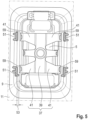
- the spring element base body 39 is in the Figure 5 with a total of four spaced-apart spring arms 41, which are extended laterally outwards. Each spring arm 41 merges into a locking web 43 which is angled away from it and which surrounds the mounting leg 17 of the mounting frame 9 on the outside.
- the locking web 43 is in the final assembly position ( Figure 4 ) in locking engagement with a locking projection 45 formed on the outside of the mounting leg 17.
- Figure 4 An intermediate assembly position is shown in which the Spring element 37 with its run-on bevels 55 are in contact with guide bevels 57 of the locking projections 45 formed on the mounting leg 17.
- the fastening arrangement 7 is spaced apart from a body-side roof frame side part 47 by a free distance a, i.e. it is free of connection to the roof frame side part 47.
- a head airbag 49 is attached to the roof frame side part 47.
- the unfolding head airbag 49 presses (in the Figure 2 indicated by dash-dotted lines) in a deployment direction E against the roof liner 3 in such a way that the roof liner swings open into the vehicle interior 1 while being deformed sideways.
- the head airbag 49 can deploy downwards into the vehicle interior 1 in the vertical direction z of the vehicle.
- the fastening arrangement 7 is assigned shielding elements 51 which support a reliable unfolding of the head airbag 49.
- Each of the shielding elements 51 is spaced from the mounting leg 17 of the mounting frame 9 via a locking clearance 53.
- the locking clearance 53 is dimensioned in such a way that a spring element assembly free of interference contours is possible.
- the shielding elements 51 are positioned only on the side facing the head airbag 49.
- shielding elements 51 are positioned both on the side facing the head airbag 49 and on the side facing away from the head airbag 49.
- the spring element base body 39 is first brought into contact with the reading light 5 inserted into the assembly shaft of the assembly frame 9.
- the spring arms 41 of the spring element 37 are then pressed with their respective locking webs 43 into the locking clearance 53 between the shielding element 51 and the assembly leg 17 of the assembly frame 9, specifically while building up the spring force F acting on the reading light 5.
- the starting flank 55 of the respective locking web 43 slides along the guide slope 57 of the locking projection 45, namely with elastic deformation of the locking web 43 outwards.
- the locking web 43 springs back towards the undeformed state and a locking recess 59 of the locking web 43 comes into locking engagement with the locking projection 45 of the mounting leg 17.
Landscapes
- Engineering & Computer Science (AREA)
- Mechanical Engineering (AREA)
- Air Bags (AREA)
- Vehicle Interior And Exterior Ornaments, Soundproofing, And Insulation (AREA)
Description
- Die Erfindung betrifft ein Fahrzeug mit einem karosseriefest verbauten Kopfairbag nach dem Oberbegriff des Anspruches 1.
- Die Karosserie- oder Rohbaustruktur eines zweispurigen Kraftfahrzeugs weist in gängiger Praxis einen Dachrahmen auf, der aus Dachrahmen-Längsträgern (das heißt Dachrahmen-Seitenteilen) und aus Dachrahmen-Querträgern aufgebaut ist. An den Dachrahmen-Seitenteilen sind unterschiedliche Anbauteile rohbaufest angebunden, etwa Halterungen für den Kopfairbag oder Einhängebauteile zum Einhängen einer Netztrennwand-Stange.
- In einem Fahrzeug wird ein karosseriefest verbauter Kopfairbag von einem Dachhimmel sichtgeschützt überdeckt. Dieser weist eine Dachhimmelöffnung für ein Funktionsteil, insbesondere Leseleuchte, auf. An der von einem Fahrzeuginnenraum abgewandten Dachhimmelrückseite ist eine Befestigungsanordnung vorgesehen, mittels der das Funktionsteil gehaltert ist.
- Bei einer Kopfairbag-Aktivierung drückt der sich entfaltende Kopfairbag derart gegen den Dachhimmel, dass sich dieser unter seitlicher Verformung in den Fahrzeuginnenraum hinein aufschwenkt. Dadurch kann sich der Kopfairbag in der Fahrzeughochrichtung nach unten in den Fahrzeuginnenraum hinein entfalten.
- Um eine ausreichende Crashsicherheit für den Fahrzeuginsassen bereitzustellen, ist es erforderlich, dass bei der Kopfairbag-Aktivierung der Entfaltungsweg des sich entfaltenden Kopfairbags zielgerichtet nach unten in Richtung Fahrzeuginnenraum ausgerichtet ist.
- Aus der
DE 10 2015 215 215 A1 ist ein gattungsgemäßer Fahrzeugdachaufbau bekannt. Aus derUS 9 278 656 B2 DE 20 2006 020 661 U1 ist ein weiteres Fahrzeug mit einem karosseriefest verbauten Kopfairbag bekannt. - Die Aufgabe der Erfindung besteht darin, ein Fahrzeug bereitzustellen, bei dem im Crashfall in konstruktiv einfacher Weise eine einwandfreie sowie crashsichere Kopfairbag-Entfaltung gewährleistet ist.
- Die Aufgabe ist durch die Merkmale des Anspruches 1 gelöst. Bevorzugte Weiterbildungen der Erfindung sind in den Unteransprüchen offenbart.
- Die Erfindung geht von einem Fahrzeug mit einem karosseriefest verbauten Kopfairbag aus, der von einem Dachhimmel sichtgeschützt überdeckt ist. Der Dachhimmel weist eine Dachhimmelöffnung für ein Funktionsteil, insbesondere eine Leseleuchte, auf. An der, vom Fahrzeuginnenraum abgewandten Dachhimmelrückseite ist eine Befestigungsanordnung vorgesehen, mittels der das Funktionsteil gehaltert wird. Die Befestigungsanordnung ragt mit einer Profilhöhe von der Dachhimmelrückseite ab. Erfindungsgemäß ist der Befestigungsanordnung zumindest ein Abschirmelement zugeordnet. Das Abschirmelement ist in einer Kopfairbag-Entfaltungsrichtung zwischen dem Kopfairbag und der Befestigungsanordnung positioniert. Auf diese Weise wird bei einer Airbagentfaltung ein scharfkantiger Bereich der Befestigungsanordnung gegenüber dem sich entfaltenden Kopfairbag abgeschirmt, wodurch eine einwandfreie sowie crashsichere Kopfairbag-Entfaltung gewährleistet ist.
- Erfindungsgemäß weist die Befestigungsanordnung einen Montagerahmen auf, der an der Dachhimmelrückseite angebunden ist. Der Montagerahmen umzieht die Dachhimmelöffnung und das Funktionsteil rahmenartig. Das Funktionsteil ist mit Hilfe eines Federelements am Montagerahmen gehaltert. Beispielhaft kann das Federelement ein Blechteil mit scharfkantigen Beschnittkanten aufweisen, das durch ein Blechumformen hergestellt ist. In diesem Fall kann das Abschirmelement speziell die scharfkantigen Bereiche am Federelement abschirmen.
- Der Montagerahmen kann beispielhaft in Klebverbindung mit der Dachhimmelrückseite sein. Für eine stabile Halterung des Funktionsteils kann der Montagerahmen im Querschnitt einen mit der Dachhimmelrückseite verbundenen äußeren Verbindungsflansch aufweisen. Dieser geht an einer inneren Übergangskante in einen davon abragenden Montageschenkel über. Der Montageschenkel des Montagerahmens begrenzt einen Montageschaft, in den das Funktionsteil in einem Setzvorgang in Richtung Fahrzeuginnenraum einsetzbar ist. Nach erfolgtem Setzvorgang ist das Funktionsteil in Anlage mit einem Endlage-Anschlag. Das Federelement bewirkt eine Lagesicherung des Funktionsteils. Hierzu spannt das Federelement das Funktionsteil in Richtung in Richtung Endlagen-Anschlag mit einer Federkraft vor.
- Wie oben erwähnt, kann das Federelement aus einem Metallblechteil gefertigt sein. Alternativ dazu kann das Federelement auch als Kunststoffteil realisiert sein. Das Federelement kann einen Grundkörper aufweisen, der den Montageschaft des Montagerahmens zumindest teilweise überdeckt. Im Zusammenbauzustand drückt der Federelement-Grundkörper das Funktionsteil mit der Federkraft gegen den Endlagen-Anschlag. Der Federelement-Grundkörper ist mit zumindest einem Federarm seitlich nach außen verlängert. Dieser geht in einen davon abgewinkelten Raststeg über. Der Raststeg des Federarms umgreift den Montageschenkel außenseitig und ist in Rasteingriff mit einer außenseitig am Montageschenkel ausgebildeten Rastkontur. Es hat sich gezeigt, dass speziell der Federarm des Federelements gegebenenfalls eine Störkontur für den sich entfaltenden Kopfairbag bilden kann. Vor diesem Hintergrund kann das Abschirmelement insbesondere den Federarm des Federelements gegenüber den sich entfaltenden Kopfairbag abschirmen.
- In einer technischen Umsetzung kann das Abschirmelement als eine Schutzrippe materialeinheitlich und einstückig am Montagerahmen angeformt sein. Die Schutzrippe kann bevorzugt am Verbindungsflansch des Montagerahmens ausgebildet sein. Zudem kann das Abschirmelement über einen Rastfreigang von der außenseitig am Montageschenkel ausgebildeten Rastkontur insbesondere in Flucht beabstandet sein. Auf diese Weise ist ein störkonturfreier Rastvorgang des Federelements durchführbar. Zudem ist im verrasteten Zustand der Raststeg des Federelements innerhalb des Rastfreigangs zwischen dem Abschirmelement und dem Montageschenkel des Montagerahmens angeordnet.
- Im Hinblick auf eine einfache Federelement-Montage kann die Montageschenkel-Rastkontur ein nach außen abragender Rastvorsprung sein, der in Rasteingriff mit einer am Raststeg des Federarms ausgebildeten Rastausnehmung bringbar ist. Für eine leichtgängige Federelement-Montage kann der Rastvorsprung eine Führungsschräge aufweisen, die bei der Federelement-Montage mit einer nach außen abgestellten Anlaufflanke des Raststegs zusammenwirkt.
- Bei der Federelement-Montage wird zunächst der Federelement-Grundkörper in Kontakt mit dem in den Montagerahmen eingesetzten Funktionsteil gebracht. Anschließend wird der Federarm des Federelements mit seinem Raststeg in den Rastfreigang zwischen dem Abschirmelement und dem Montageschenkel des Montagerahmens gedrückt. Dies erfolgt unter Aufbau der auf das Funktionsteil wirkenden Federkraft. Während der Federelement-Montage leitet die Anlaufflanke des Raststegs entlang der Führungsschräge des Rastvorsprungs, und zwar unter elastischer Verformung des Raststegs. Nach Überwinden des Rastvorsprung springt der Raststeg in Richtung unverformten Zustand zurück und kommt die Rastausnehmung im Raststeg in Rasteingriff mit dem Montageschenkel-Rastvorsprung.
- Die Befestigungsanordnung des Funktionsteils ist bevorzugt über einen freien Abstand von der Karosseriestruktur des Fahrzeugs beabstandet, das heißt gegenüber der Karosseriestruktur anbindungsfrei. Der Endlagen-Anschlag kann mittels einer rahmenartigen Funktionsteilblende realisiert sein. Diese kann im Querschnitt betrachtet einen Stützschenkel aufweisen, der in Zusammenbaulage an der Dachhimmelsichtseite auf dem Öffnungsrandbereich der Dachhimmelöffnung abgestützt ist. Der Stützschenkel der Funktionsteil-Blende kann an einer inneren Übergangskante in einen davon abgewinkelten Rastschenkel übergehen. Im Zusammenbauzustand ist dieser in Rasteingriff mit einen innenseitig am Montageschenkel ausgebildeten Rastkontur. Der Stützschenkel der Funktionsteil-Blende kann über den Rastschenkel hinweg mit einem Überstand nach innen verlängert sein. Auf diese Weise bildet der Überstand den Endlagen-Anschlag für das Funktionsteil.
- Nachfolgend ist ein Ausführungsbeispiel der Erfindung anhand der beigefügten Figuren beschrieben.
- Es zeigen:
- Figur 1
- in einer Seitenansicht ein zweispuriges Fahrzeug mit teilweisem Aufriss, der eine Leseleuchte in Einbaulage zeigt;
- Figur 2
- eine vergrößerte Schnittdarstellung entlang einer Schnittebene A-A aus der
Figur 1 ; - Figuren 3 und 4
- jeweils Schnittdarstellungen der Befestigungsanordnung der Leseleuchte in einer Zwischenmontageposition (
Figur 3 ) und in einer Endmontageposition (Figur 4 ); und - Figur 5
- die Befestigungsanordnung in einer Ansicht von oben.
- Der Stützschenkel 25 der Leseleuchten-Blende 23 ist gemäß der
Figur 3 über den Rastschenkel 33 hinweg mit einem Überstand nach innen verlängert, der den Endlagen-Anschlag 21 bildet. - Für eine lagesichere Positionierung der Leseleuchte 5 am Endlagen-Anschlag 21 weist die Befestigungsanordnung 7 ein Federelement 37 auf, das die Leseleuchte 5 in Richtung Endlagen-Anschlag 21 mit einer Federkraft F vorspannt. Das Federelement 37 kann ein Metallblechteil sein, das durch Blechumformung hergestellt ist. In den
Figuren 2 bis 5 weist das Federelement 37 einen Grundkörper 39 auf, der den Montageschaft des Montagerahmens 9 teilweise überdeckt und die Leseleuchte 5 mit der Federkraft F gegen den Endlagen-Anschlag 21 drückt. Der Federelement-Grundkörper 39 ist in derFigur 5 mit insgesamt vier voneinander beabstandeten Federarmen 41 seitlich nach außen verlängert. Jeder Federarm 41 geht in einen davon abgewinkelten Raststeg 43 über, der den Montageschenkel 17 des Montagerahmens 9 außenseitig umgreift. Der Raststeg 43 ist in der Endmontageposition (Figur 4 ) in Rasteingriff mit einem außenseitig am Montageschenkel 17 angeformten Rastvorsprung 45. Demgegenüber ist in derFigur 3 und in derFigur 4 eine Zwischenmontageposition gezeigt, in der das Federelement 37 mit seinen Anlaufschrägen 55 in Kontakt mit Führungsschrägen 57 der am Montageschenkel 17 ausgebildeten Rastvorsprünge 45 sind. - Gemäß der
Figur 2 ist die Befestigungsanordnung 7 gegenüber einem karosserieseitigen Dachrahmenseitenteil 47 über einen freien Abstand a beabstandet, das heißt gegenüber dem Dachrahmenseitenteil 47 anbindungsfrei. Am Dachrahmenseitenteil 47 ist ein Kopfairbag 49 befestigt. Bei einer Kopfairbag-Aktivierung drückt der sich entfaltende Kopfairbag 49 (in derFigur 2 strichpunktiert angedeutet) in einer Entfaltungsrichtung E derart gegen den Dachhimmel 3, dass sich dieser unter seitlicher Verformung in den Fahrzeuginnenraum 1 hinein aufschwenkt. Dadurch kann sich der Kopfairbag 49 in der Fahrzeughochrichtung z nach unten in den Fahrzeuginnenraum 1 hinein entfalten. - Um einen störkonturfreien Entfaltungsvorgang zu gewährleisten, sind der Befestigungsanordnung 7 Abschirmelemente 51 zugeordnet, die eine prozesssichere Entfaltung des Kopfairbags 49 unterstützen. Jedes der Abschirmelemente 51 ist über einen Rastfreigang 53 von dem Montageschenkel 17 des Montagerahmens 9 beabstandet. Der Rastfreigang 53 ist derart bemessen, dass eine störkonturfreie Federelement-Montage ermöglicht ist. In den
Figuren 2 bis 4 sind die Abschirmelemente 51 nur an der, dem Kopfairbag 49 zugewandten Seite positioniert. Demgegenüber sind in derFigur 5 beispielhaft sowohl an der, dem Kopfairbag 49 zugewandten Seite als auch an der an vom Kopfairbag 49 abgewandten Seite Abschirmelemente 51 positioniert. - Für die Federelement-Montage wird zunächst der Federelement-Grundkörper 39 in Kontakt mit der in den Montageschaft des Montagerahmen 9 eingesetzten Leseleuchte 5 gebracht. Anschließend werden die Federarme 41 des Federelements 37 mit ihren jeweiligen Raststegen 43 in den Rastfreigang 53 zwischen dem Abschirmelement 51 und dem Montageschenkel 17 des Montagerahmens 9 gedrückt, und zwar unter Aufbau der auf die Leseleuchte 5 wirkenden Federkraft F.
- Während der Federelement-Montage gleitet die Anlaufflanke 55 des jeweiligen Raststegs 43 entlang der Führungsschräge 57 des Rastvorsprungs 45, und zwar unter elastischer Verformung des Raststegs 43 nach außen. Nach Überwinden des Rastvorsprungs 45 springt der Raststeg 43 in Richtung unverformten Zustand zurück und kommt eine Rastausnehmung 59 des Raststegs 43 in Rasteingriff mit dem Rastvorsprung 45 des Montageschenkels 17.
-
- 1
- Fahrzeuginnenraum
- 3
- Dachhimmel
- 5
- Funktionsteil
- 7
- Befestigungsanordnung
- 9
- Montagerahmen
- 11
- Dachhimmelrückseite
- 13
- Verbindungsflansch
- 15
- Übergangskante
- 17
- Montageschenkel
- 21
- Endlagen-Anschlag
- 23
- Leseleuchten-Blende
- 25
- Stützschenkel
- 27
- Dachhimmelsichtseite
- 29
- Dachhimmelöffnung
- 33
- Rastschenkel
- 35
- Rastkontur
- 37
- Federelement
- 39
- Federelement-Grundkörper
- 41
- Federarm
- 43
- Raststeg
- 45
- Rastvorsprung
- 47
- Dachrahmenseitenteil
- 49
- Kopfairbag
- 51
- Abschirmelement
- 53
- Rastfreigang
- 55
- Anlaufflanke
- 57
- Führungsschräge
- 59
- Rastausnehmung
- E
- Entfaltungsrichtung
- F
- Federkraft
- a
- freier Abstand
- S
- Setzvorgang
Claims (9)
- Fahrzeug mit einem karosseriefest verbauten Kopfairbag (49), der von einem Dachhimmel (3) sichtgeschützt überdeckt ist, der eine Dachhimmelöffnung (29) für ein Funktionsteil (5), insbesondere Leseleuchte, aufweist, wobei an der von einem Fahrzeuginnenraum (1) abgewandten Dachhimmelrückseite (11) eine Befestigungsanordnung (7) vorgesehen ist, mittels der das Funktionsteil (5) gehaltert ist, wobei der Befestigungsanordnung (7) zumindest ein Abschirmelement (51) zugeordnet ist, das in einer Kopfairbag-Entfaltungsrichtung (E) zwischen dem Kopfairbag (49) und der Befestigungsanordnung (7) angeordnet ist, so dass bei einer Airbagentfaltung ein störkonturbehafteter Bereich der Befestigungsanordnung (7) gegenüber dem sich entfaltenden Kopfairbag (49) abgeschirmt ist, dadurch gekennzeichnet, dass die Befestigungsanordnung (7) einen Montagerahmen (9) aufweist, der an die Dachhimmelrückseite (11) angebunden ist und die Dachhimmelöffnung (29) sowie das Funktionsteil (5) rahmenartig umzieht, und dass das Funktionsteil (5) mit Hilfe eines Federelements (37) am Montagerahmen (9) gehaltert ist, und dass der vom Abschirmelement (51) abgeschirmte störkonturbehaftete Bereich am Federelement (37) ausgebildet ist.
- Fahrzeug nach Anspruch 1, dadurch gekennzeichnet, dass der Montagerahmen (9) im Querschnitt einen mit der Dachhimmelrückseite (11) verbundenen, äußeren Verbindungsflansch (13) aufweist, der an einer inneren Übergangskante in einen davon abragenden Montageschenkel (17) übergeht, und dass der Montageschenkel (17) des Montagerahmens (9) einen Montageschaft begrenzt, in den das Funktionsteil (5) in einem Setzvorgang (S) in Richtung Fahrzeuginnenraum (1) einsetzbar ist, und zwar bis in Anlage mit einem Endlagen-Anschlag (21), und dass zur Lagesicherung das Federelement (37) das Funktionsteil (5) in Richtung Endlagen-Anschlag (21) mit einer Federkraft (F) vorspannt.
- Fahrzeug nach Anspruch 2, dadurch gekennzeichnet, dass das Federelement (37) einen Grundkörper (39) aufweist, der den Montageschaft des Montagerahmens (9) zumindest teilweise überdeckt und/oder das Funktionsteil (5) mit der Federkraft (F) gegen den Endlagen-Anschlag (21) drückt, und dass insbesondere der Federelement-Grundkörper (39) mit zumindest einem Federarm (41) seitlich nach außen verlängert ist, der in einen davon abgewinkelten Raststeg (43) übergeht, und dass der Raststeg (43) des Federarms (41) den Montageschenkel (17) außenseitig übergreift und/oder in Rasteingriff mit einer außenseitig am Montageschenkel (17) ausgebildeten Rastkontur (45) ist, und/oder dass insbesondere der Federarm (41) des Federelements (37) den von dem Abschirmelement (51) abgeschirmten störkonturbehafteten Bereich bildet.
- Fahrzeug nach einem der Ansprüche 1 bis 3, dadurch gekennzeichnet, dass das Abschirmelement (51) als eine Schutzrippe materialeinheitlich und einstückig am Montagerahmen (9) angeformt ist, insbesondere am Verbindungsflansch (13) des Montagerahmens (9), und/oder dass insbesondere das Abschirmelement (51) über einen Rastfreigang (53) von der außenseitig am Montageschenkel (17) ausgebildeten Rastkontur (45), insbesondere in Flucht, beabstandet ist, so dass insbesondere ein störkonturfreier Rastvorgang des Federelements (37) durchführbar ist, und/oder dass im verrasteten Zustand der Raststeg (43) des Federelements (37) im Rastfreigang (53) zwischen dem Abschirmelement (51) und dem Montageschenkel (17) des Montagerahmens (9) angeordnet ist.
- Fahrzeug nach Anspruch 3 oder 4, dadurch gekennzeichnet, dass die Montageschenkel-Rastkontur (45) ein nach außen abragender Rastvorsprung ist, der in Rasteingriff mit einer am Raststeg (43) des Federarms (41) ausgebildeten Rastausnehmung (59) bringbar ist, und dass insbesondere der Rastvorsprung (45) eine Führungsschräge (57) aufweist, die bei einer Federelement-Montage mit einer nach außen abgestellten Anlaufflanke (55) des Raststegs (43) zusammenwirkt.
- Fahrzeug nach Anspruch 5, dadurch gekennzeichnet, dass für die Federelement-Montage der Federelement-Grundkörper (39) in Kontakt mit dem in den Montagerahmen (9) eingesetzten Funktionsteil (5) gebracht wird, und anschließend der Federarm (41) des Federelements (37) mit seinem Raststeg (43) in den Rastfreigang (53) zwischen dem Abschirmelement (51) und dem Montageschenkel (17) des Montagerahmens (9) gedrückt wird, und zwar unter Aufbau der auf das Funktionsteil (5) wirkenden Federkraft (F).
- Fahrzeug nach Anspruch 6, dadurch gekennzeichnet, dass während der Federelement-Montage die Anlaufflanke (55) des Raststegs (43) entlang der Führungsschräge (57) des Rastvorsprungs (45) gleitet, und zwar unter elastischer Verformung des Raststegs (43), und dass nach Überwinden des Rastvorsprungs (45) der Raststeg (43) in Richtung unverformten Zustand zurückspringt und die Rastausnehmung (59) des Raststegs (43) in Rasteingriff mit dem Rastvorsprung (45) des Montageschenkel (9) kommt.
- Fahrzeug nach einem der Ansprüche 2 bis 5, dadurch gekennzeichnet, dass der Endlagen-Anschlag (21) in einer rahmenartigen Funktionsteil-Blende (23) ausgebildet ist, und dass die Funktionsteil-Blende (23) im Querschnitt einen Stützschenkel (25) aufweist, der an der Dachhimmelsichtseite (27) auf dem Öffnungsrandbereich der Dachhimmelöffnung (29) abgestützt ist, und dass insbesondere der Stützschenkel (25) an einer inneren Übergangskante in einen davon abgewinkelten Rastschenkel (33) übergeht, der in Rasteingriff mit einer innenseitig am Montageschenkel (17) ausgebildeten Rastkontur (35) ist, und dass insbesondere der Stützschenkel (25) der Funktionsteil-Blende (23) über den Rastschenkel (33) hinweg mit einem Überstand nach innen verlängert ist, und dass der Überstand den Endlagen-Anschlag (21) bildet.
- Fahrzeug nach einem der vorhergehenden Ansprüche, dadurch gekennzeichnet, dass das Federelement (37) ein Blechteil mit scharfkantigen Beschnittkanten ist, das durch Blechumformen hergestellt ist.
Applications Claiming Priority (1)
| Application Number | Priority Date | Filing Date | Title |
|---|---|---|---|
| DE102021210517.3A DE102021210517A1 (de) | 2021-09-22 | 2021-09-22 | Fahrzeug mit einem karosseriefest verbauten Kopfairbag |
Publications (2)
| Publication Number | Publication Date |
|---|---|
| EP4155137A1 EP4155137A1 (de) | 2023-03-29 |
| EP4155137B1 true EP4155137B1 (de) | 2025-02-26 |
Family
ID=83232729
Family Applications (1)
| Application Number | Title | Priority Date | Filing Date |
|---|---|---|---|
| EP22194313.7A Active EP4155137B1 (de) | 2021-09-22 | 2022-09-07 | Fahrzeug mit einem karosseriefest verbauten kopfairbag |
Country Status (6)
| Country | Link |
|---|---|
| US (1) | US12269411B2 (de) |
| EP (1) | EP4155137B1 (de) |
| JP (1) | JP7470163B2 (de) |
| KR (1) | KR102863370B1 (de) |
| CN (1) | CN115891896A (de) |
| DE (1) | DE102021210517A1 (de) |
Family Cites Families (18)
| Publication number | Priority date | Publication date | Assignee | Title |
|---|---|---|---|---|
| JP3052085B1 (ja) * | 1999-04-15 | 2000-06-12 | 本田技研工業株式会社 | 乗員拘束装置 |
| JP3485038B2 (ja) | 1999-08-20 | 2004-01-13 | トヨタ自動車株式会社 | 頭部保護エアバッグ搭載車両の内装品取付構造 |
| JP4684111B2 (ja) | 2006-01-30 | 2011-05-18 | 日本プラスト株式会社 | 自動車のルーフサイドガーニッシュ周辺構造 |
| DE102006041924A1 (de) | 2006-09-07 | 2008-03-27 | Volkswagen Ag | Befestigungsclip, insbesondere zur Befestigung eines Airbagmoduls in einem Fahrzeug, sowie Verfahren zur Befestigung eines Airbagmoduls |
| DE102006055507A1 (de) * | 2006-11-24 | 2008-06-05 | Dr.Ing.H.C. F. Porsche Ag | Kraftfahrzeug mit einem kopfschützenden Seitenairbag |
| JP5130118B2 (ja) | 2007-09-14 | 2013-01-30 | 矢崎総業株式会社 | 車載用室内照明装置 |
| JP5184963B2 (ja) | 2008-05-14 | 2013-04-17 | 本田技研工業株式会社 | 車室内部品 |
| WO2012099105A1 (ja) * | 2011-01-17 | 2012-07-26 | オートリブ ディベロップメント エービー | カバー及びエアバッグ装置 |
| US8827516B2 (en) * | 2011-11-30 | 2014-09-09 | Ford Global Technologies, Llc | Modular grab handle with integral lamp attaching system |
| JP5568648B2 (ja) | 2013-01-15 | 2014-08-06 | 本田技研工業株式会社 | 車室内部品 |
| US9278656B2 (en) | 2014-05-07 | 2016-03-08 | Toyota Motor Engineering & Manufacturing North America, Inc. | Protection shield for vehicle headliner |
| JP2016043739A (ja) * | 2014-08-20 | 2016-04-04 | トヨタ自動車株式会社 | 車両用天井構造 |
| DE102015202858A1 (de) * | 2015-02-17 | 2016-08-18 | Volkswagen Aktiengesellschaft | Fahrzeugkarosserie mit einer Montageanordnung zum Einhängen einer Netztrennwand-Stange |
| CN205737309U (zh) * | 2016-05-23 | 2016-11-30 | 奇瑞捷豹路虎汽车有限公司 | 用于车辆的b柱内饰板及车辆 |
| JP6768566B2 (ja) * | 2017-03-13 | 2020-10-14 | 豊田合成株式会社 | 頭部保護エアバッグ装置 |
| JP6908005B2 (ja) * | 2018-06-25 | 2021-07-21 | 豊田合成株式会社 | 頭部保護エアバッグ装置 |
| US11130386B2 (en) | 2019-09-27 | 2021-09-28 | Toyota Motor Engineering & Manufacturing North America, Inc. | Rigid endcap for a duct system in a headliner |
| CN212148752U (zh) * | 2020-03-25 | 2020-12-15 | 一汽奔腾轿车有限公司 | 一种乘用车侧气帘爆破钣金导向结构 |
-
2021
- 2021-09-22 DE DE102021210517.3A patent/DE102021210517A1/de active Pending
-
2022
- 2022-09-07 EP EP22194313.7A patent/EP4155137B1/de active Active
- 2022-09-21 US US17/949,800 patent/US12269411B2/en active Active
- 2022-09-21 JP JP2022149920A patent/JP7470163B2/ja active Active
- 2022-09-22 CN CN202211155447.7A patent/CN115891896A/zh active Pending
- 2022-09-22 KR KR1020220120076A patent/KR102863370B1/ko active Active
Also Published As
| Publication number | Publication date |
|---|---|
| KR20230042665A (ko) | 2023-03-29 |
| JP7470163B2 (ja) | 2024-04-17 |
| JP2023046308A (ja) | 2023-04-03 |
| EP4155137A1 (de) | 2023-03-29 |
| CN115891896A (zh) | 2023-04-04 |
| US20230091811A1 (en) | 2023-03-23 |
| KR102863370B1 (ko) | 2025-09-22 |
| US12269411B2 (en) | 2025-04-08 |
| DE102021210517A1 (de) | 2023-03-23 |
Similar Documents
| Publication | Publication Date | Title |
|---|---|---|
| DE102006053990B4 (de) | Konstruktion zur Befestigung einer Innenabdeckung an einer Fahrzeug-A-Säule | |
| DE10344778B4 (de) | Befestigungsstruktur für eine Säulenverkleidung in einem Kraftfahrzeug mit einem vorhangartigen Airbag | |
| DE60301938T2 (de) | Vorhang-Airbageinrichtung | |
| EP1925503B1 (de) | Kraftfahrzeug mit einem kopfschützenden Seitenairbag | |
| DE19919505A1 (de) | Fahrzeugdach mit eingesetztem Dachmodul und Montageverfahren dafür | |
| EP3286042B1 (de) | Lenkradeinheit, gassackmodul und lenkradkörper | |
| DE102008021265A1 (de) | Kraftfahrzeug mit A-Säule und in dieser gelagertem Airbag | |
| DE102009049764B4 (de) | Airbaganordnung | |
| DE102005010024B4 (de) | Fahrzeugtürverkleidung und Verfahren zu deren Herstellung | |
| DE102008022427A1 (de) | Kraftfahrzeug mit A-Säule und in dieser gelagerten Airbag | |
| DE102005010025B4 (de) | Fahrzeugtürverkleidung und Verfahren zu deren Herstellung | |
| DE19620538A1 (de) | Abdeckung für einen Airbag | |
| DE10041763B4 (de) | Airbag-Befestigung | |
| EP4155137B1 (de) | Fahrzeug mit einem karosseriefest verbauten kopfairbag | |
| EP1600338B1 (de) | Kraftfahrzeug mit einem Energie absorbierenden Deformationselement | |
| DE102015209111A1 (de) | Befestigungsanordnung zur Befestigung eines Airbags an einer karosserieseitigen Trägerwand eines Fahrzeugs | |
| EP3925832B1 (de) | Fahrzeugkarosserie | |
| DE102017003502A1 (de) | Fahrzeugdach mit einem gesicherten Dachflächenteil | |
| DE10254773A1 (de) | Modulares Fahrzeugdach | |
| DE10349520B4 (de) | Gehäuse zur Aufnahme eines Kraftfahrzeug-Airbagmoduls | |
| EP3736172B1 (de) | Fahrzeug mit einer montageanordnung zum einhängen eines bauteils | |
| DE29921857U1 (de) | Fahrzeuginsassen-Rückhaltesystem | |
| WO2011120682A1 (de) | Modularer karosserieaufbau eines kraftfahrzeugs | |
| DE102018205809B4 (de) | Trägerelement zum Befestigen eines Innenverkleidungsteils an einem Bauteil eines Fahrzeugs. | |
| DE102016120987A1 (de) | Gassack für ein Kraftfahrzeug sowie Verfahren zur Herstellung eines solchen Gassacks |
Legal Events
| Date | Code | Title | Description |
|---|---|---|---|
| PUAI | Public reference made under article 153(3) epc to a published international application that has entered the european phase |
Free format text: ORIGINAL CODE: 0009012 |
|
| STAA | Information on the status of an ep patent application or granted ep patent |
Free format text: STATUS: THE APPLICATION HAS BEEN PUBLISHED |
|
| AK | Designated contracting states |
Kind code of ref document: A1 Designated state(s): AL AT BE BG CH CY CZ DE DK EE ES FI FR GB GR HR HU IE IS IT LI LT LU LV MC MK MT NL NO PL PT RO RS SE SI SK SM TR |
|
| STAA | Information on the status of an ep patent application or granted ep patent |
Free format text: STATUS: REQUEST FOR EXAMINATION WAS MADE |
|
| 17P | Request for examination filed |
Effective date: 20230905 |
|
| RBV | Designated contracting states (corrected) |
Designated state(s): AL AT BE BG CH CY CZ DE DK EE ES FI FR GB GR HR HU IE IS IT LI LT LU LV MC MK MT NL NO PL PT RO RS SE SI SK SM TR |
|
| GRAP | Despatch of communication of intention to grant a patent |
Free format text: ORIGINAL CODE: EPIDOSNIGR1 |
|
| STAA | Information on the status of an ep patent application or granted ep patent |
Free format text: STATUS: GRANT OF PATENT IS INTENDED |
|
| INTG | Intention to grant announced |
Effective date: 20240920 |
|
| GRAS | Grant fee paid |
Free format text: ORIGINAL CODE: EPIDOSNIGR3 |
|
| GRAA | (expected) grant |
Free format text: ORIGINAL CODE: 0009210 |
|
| STAA | Information on the status of an ep patent application or granted ep patent |
Free format text: STATUS: THE PATENT HAS BEEN GRANTED |
|
| AK | Designated contracting states |
Kind code of ref document: B1 Designated state(s): AL AT BE BG CH CY CZ DE DK EE ES FI FR GB GR HR HU IE IS IT LI LT LU LV MC MK MT NL NO PL PT RO RS SE SI SK SM TR |
|
| P01 | Opt-out of the competence of the unified patent court (upc) registered |
Free format text: CASE NUMBER: APP_3152/2025 Effective date: 20250120 |
|
| REG | Reference to a national code |
Ref country code: GB Ref legal event code: FG4D Free format text: NOT ENGLISH |
|
| REG | Reference to a national code |
Ref country code: CH Ref legal event code: EP |
|
| REG | Reference to a national code |
Ref country code: DE Ref legal event code: R096 Ref document number: 502022003012 Country of ref document: DE |
|
| REG | Reference to a national code |
Ref country code: IE Ref legal event code: FG4D Free format text: LANGUAGE OF EP DOCUMENT: GERMAN |
|
| REG | Reference to a national code |
Ref country code: NL Ref legal event code: MP Effective date: 20250226 |
|
| PG25 | Lapsed in a contracting state [announced via postgrant information from national office to epo] |
Ref country code: RS Free format text: LAPSE BECAUSE OF FAILURE TO SUBMIT A TRANSLATION OF THE DESCRIPTION OR TO PAY THE FEE WITHIN THE PRESCRIBED TIME-LIMIT Effective date: 20250526 |
|
| PG25 | Lapsed in a contracting state [announced via postgrant information from national office to epo] |
Ref country code: FI Free format text: LAPSE BECAUSE OF FAILURE TO SUBMIT A TRANSLATION OF THE DESCRIPTION OR TO PAY THE FEE WITHIN THE PRESCRIBED TIME-LIMIT Effective date: 20250226 |
|
| PG25 | Lapsed in a contracting state [announced via postgrant information from national office to epo] |
Ref country code: PL Free format text: LAPSE BECAUSE OF FAILURE TO SUBMIT A TRANSLATION OF THE DESCRIPTION OR TO PAY THE FEE WITHIN THE PRESCRIBED TIME-LIMIT Effective date: 20250226 |
|
| PG25 | Lapsed in a contracting state [announced via postgrant information from national office to epo] |
Ref country code: ES Free format text: LAPSE BECAUSE OF FAILURE TO SUBMIT A TRANSLATION OF THE DESCRIPTION OR TO PAY THE FEE WITHIN THE PRESCRIBED TIME-LIMIT Effective date: 20250226 |
|
| REG | Reference to a national code |
Ref country code: LT Ref legal event code: MG9D |
|
| PG25 | Lapsed in a contracting state [announced via postgrant information from national office to epo] |
Ref country code: NO Free format text: LAPSE BECAUSE OF FAILURE TO SUBMIT A TRANSLATION OF THE DESCRIPTION OR TO PAY THE FEE WITHIN THE PRESCRIBED TIME-LIMIT Effective date: 20250526 Ref country code: IS Free format text: LAPSE BECAUSE OF FAILURE TO SUBMIT A TRANSLATION OF THE DESCRIPTION OR TO PAY THE FEE WITHIN THE PRESCRIBED TIME-LIMIT Effective date: 20250626 |
|
| PG25 | Lapsed in a contracting state [announced via postgrant information from national office to epo] |
Ref country code: NL Free format text: LAPSE BECAUSE OF FAILURE TO SUBMIT A TRANSLATION OF THE DESCRIPTION OR TO PAY THE FEE WITHIN THE PRESCRIBED TIME-LIMIT Effective date: 20250226 |
|
| PG25 | Lapsed in a contracting state [announced via postgrant information from national office to epo] |
Ref country code: HR Free format text: LAPSE BECAUSE OF FAILURE TO SUBMIT A TRANSLATION OF THE DESCRIPTION OR TO PAY THE FEE WITHIN THE PRESCRIBED TIME-LIMIT Effective date: 20250226 |
|
| PG25 | Lapsed in a contracting state [announced via postgrant information from national office to epo] |
Ref country code: LV Free format text: LAPSE BECAUSE OF FAILURE TO SUBMIT A TRANSLATION OF THE DESCRIPTION OR TO PAY THE FEE WITHIN THE PRESCRIBED TIME-LIMIT Effective date: 20250226 Ref country code: PT Free format text: LAPSE BECAUSE OF FAILURE TO SUBMIT A TRANSLATION OF THE DESCRIPTION OR TO PAY THE FEE WITHIN THE PRESCRIBED TIME-LIMIT Effective date: 20250626 |
|
| PG25 | Lapsed in a contracting state [announced via postgrant information from national office to epo] |
Ref country code: BG Free format text: LAPSE BECAUSE OF FAILURE TO SUBMIT A TRANSLATION OF THE DESCRIPTION OR TO PAY THE FEE WITHIN THE PRESCRIBED TIME-LIMIT Effective date: 20250226 Ref country code: GR Free format text: LAPSE BECAUSE OF FAILURE TO SUBMIT A TRANSLATION OF THE DESCRIPTION OR TO PAY THE FEE WITHIN THE PRESCRIBED TIME-LIMIT Effective date: 20250527 |
|
| PG25 | Lapsed in a contracting state [announced via postgrant information from national office to epo] |
Ref country code: SE Free format text: LAPSE BECAUSE OF FAILURE TO SUBMIT A TRANSLATION OF THE DESCRIPTION OR TO PAY THE FEE WITHIN THE PRESCRIBED TIME-LIMIT Effective date: 20250226 |
|
| PG25 | Lapsed in a contracting state [announced via postgrant information from national office to epo] |
Ref country code: SM Free format text: LAPSE BECAUSE OF FAILURE TO SUBMIT A TRANSLATION OF THE DESCRIPTION OR TO PAY THE FEE WITHIN THE PRESCRIBED TIME-LIMIT Effective date: 20250226 |
|
| PG25 | Lapsed in a contracting state [announced via postgrant information from national office to epo] |
Ref country code: DK Free format text: LAPSE BECAUSE OF FAILURE TO SUBMIT A TRANSLATION OF THE DESCRIPTION OR TO PAY THE FEE WITHIN THE PRESCRIBED TIME-LIMIT Effective date: 20250226 |
|
| PGFP | Annual fee paid to national office [announced via postgrant information from national office to epo] |
Ref country code: DE Payment date: 20250930 Year of fee payment: 4 |
|
| PG25 | Lapsed in a contracting state [announced via postgrant information from national office to epo] |
Ref country code: IT Free format text: LAPSE BECAUSE OF FAILURE TO SUBMIT A TRANSLATION OF THE DESCRIPTION OR TO PAY THE FEE WITHIN THE PRESCRIBED TIME-LIMIT Effective date: 20250226 |
|
| PGFP | Annual fee paid to national office [announced via postgrant information from national office to epo] |
Ref country code: AT Payment date: 20251020 Year of fee payment: 4 Ref country code: FR Payment date: 20250925 Year of fee payment: 4 |
|
| PG25 | Lapsed in a contracting state [announced via postgrant information from national office to epo] |
Ref country code: CZ Free format text: LAPSE BECAUSE OF FAILURE TO SUBMIT A TRANSLATION OF THE DESCRIPTION OR TO PAY THE FEE WITHIN THE PRESCRIBED TIME-LIMIT Effective date: 20250226 Ref country code: EE Free format text: LAPSE BECAUSE OF FAILURE TO SUBMIT A TRANSLATION OF THE DESCRIPTION OR TO PAY THE FEE WITHIN THE PRESCRIBED TIME-LIMIT Effective date: 20250226 |
|
| PG25 | Lapsed in a contracting state [announced via postgrant information from national office to epo] |
Ref country code: RO Free format text: LAPSE BECAUSE OF FAILURE TO SUBMIT A TRANSLATION OF THE DESCRIPTION OR TO PAY THE FEE WITHIN THE PRESCRIBED TIME-LIMIT Effective date: 20250226 |
|
| PG25 | Lapsed in a contracting state [announced via postgrant information from national office to epo] |
Ref country code: SK Free format text: LAPSE BECAUSE OF FAILURE TO SUBMIT A TRANSLATION OF THE DESCRIPTION OR TO PAY THE FEE WITHIN THE PRESCRIBED TIME-LIMIT Effective date: 20250226 |
|
| REG | Reference to a national code |
Ref country code: DE Ref legal event code: R097 Ref document number: 502022003012 Country of ref document: DE |
|
| PLBE | No opposition filed within time limit |
Free format text: ORIGINAL CODE: 0009261 |
|
| STAA | Information on the status of an ep patent application or granted ep patent |
Free format text: STATUS: NO OPPOSITION FILED WITHIN TIME LIMIT |
|
| 26N | No opposition filed |
Effective date: 20251127 |