EP4154969B1 - Klimaanlagendrehkörper und luftbehandlungsvorrichtung - Google Patents
Klimaanlagendrehkörper und luftbehandlungsvorrichtung Download PDFInfo
- Publication number
- EP4154969B1 EP4154969B1 EP21853887.4A EP21853887A EP4154969B1 EP 4154969 B1 EP4154969 B1 EP 4154969B1 EP 21853887 A EP21853887 A EP 21853887A EP 4154969 B1 EP4154969 B1 EP 4154969B1
- Authority
- EP
- European Patent Office
- Prior art keywords
- rotor
- air
- rotating body
- air conditioning
- conditioning rotating
- Prior art date
- Legal status (The legal status is an assumption and is not a legal conclusion. Google has not performed a legal analysis and makes no representation as to the accuracy of the status listed.)
- Active
Links
Images


Classifications
-
- B—PERFORMING OPERATIONS; TRANSPORTING
- B01—PHYSICAL OR CHEMICAL PROCESSES OR APPARATUS IN GENERAL
- B01D—SEPARATION
- B01D53/00—Separation of gases or vapours; Recovering vapours of volatile solvents from gases; Chemical or biological purification of waste gases, e.g. engine exhaust gases, smoke, fumes, flue gases, aerosols
- B01D53/02—Separation of gases or vapours; Recovering vapours of volatile solvents from gases; Chemical or biological purification of waste gases, e.g. engine exhaust gases, smoke, fumes, flue gases, aerosols by adsorption, e.g. preparative gas chromatography
- B01D53/06—Separation of gases or vapours; Recovering vapours of volatile solvents from gases; Chemical or biological purification of waste gases, e.g. engine exhaust gases, smoke, fumes, flue gases, aerosols by adsorption, e.g. preparative gas chromatography with moving adsorbents, e.g. rotating beds
-
- B—PERFORMING OPERATIONS; TRANSPORTING
- B01—PHYSICAL OR CHEMICAL PROCESSES OR APPARATUS IN GENERAL
- B01D—SEPARATION
- B01D53/00—Separation of gases or vapours; Recovering vapours of volatile solvents from gases; Chemical or biological purification of waste gases, e.g. engine exhaust gases, smoke, fumes, flue gases, aerosols
- B01D53/26—Drying gases or vapours
- B01D53/261—Drying gases or vapours by adsorption
-
- F—MECHANICAL ENGINEERING; LIGHTING; HEATING; WEAPONS; BLASTING
- F24—HEATING; RANGES; VENTILATING
- F24F—AIR-CONDITIONING; AIR-HUMIDIFICATION; VENTILATION; USE OF AIR CURRENTS FOR SCREENING
- F24F3/00—Air-conditioning systems in which conditioned primary air is supplied from one or more central stations to distributing units in the rooms or spaces where it may receive secondary treatment; Apparatus specially designed for such systems
- F24F3/12—Air-conditioning systems in which conditioned primary air is supplied from one or more central stations to distributing units in the rooms or spaces where it may receive secondary treatment; Apparatus specially designed for such systems characterised by the treatment of the air otherwise than by heating and cooling
- F24F3/14—Air-conditioning systems in which conditioned primary air is supplied from one or more central stations to distributing units in the rooms or spaces where it may receive secondary treatment; Apparatus specially designed for such systems characterised by the treatment of the air otherwise than by heating and cooling by humidification; by dehumidification
- F24F3/1411—Air-conditioning systems in which conditioned primary air is supplied from one or more central stations to distributing units in the rooms or spaces where it may receive secondary treatment; Apparatus specially designed for such systems characterised by the treatment of the air otherwise than by heating and cooling by humidification; by dehumidification by absorbing or adsorbing water, e.g. using an hygroscopic desiccant
- F24F3/1423—Air-conditioning systems in which conditioned primary air is supplied from one or more central stations to distributing units in the rooms or spaces where it may receive secondary treatment; Apparatus specially designed for such systems characterised by the treatment of the air otherwise than by heating and cooling by humidification; by dehumidification by absorbing or adsorbing water, e.g. using an hygroscopic desiccant with a moving bed of solid desiccants, e.g. a rotary wheel supporting solid desiccants
-
- F—MECHANICAL ENGINEERING; LIGHTING; HEATING; WEAPONS; BLASTING
- F24—HEATING; RANGES; VENTILATING
- F24F—AIR-CONDITIONING; AIR-HUMIDIFICATION; VENTILATION; USE OF AIR CURRENTS FOR SCREENING
- F24F3/00—Air-conditioning systems in which conditioned primary air is supplied from one or more central stations to distributing units in the rooms or spaces where it may receive secondary treatment; Apparatus specially designed for such systems
- F24F3/12—Air-conditioning systems in which conditioned primary air is supplied from one or more central stations to distributing units in the rooms or spaces where it may receive secondary treatment; Apparatus specially designed for such systems characterised by the treatment of the air otherwise than by heating and cooling
- F24F3/16—Air-conditioning systems in which conditioned primary air is supplied from one or more central stations to distributing units in the rooms or spaces where it may receive secondary treatment; Apparatus specially designed for such systems characterised by the treatment of the air otherwise than by heating and cooling by purification, e.g. by filtering; by sterilisation; by ozonisation
-
- B—PERFORMING OPERATIONS; TRANSPORTING
- B01—PHYSICAL OR CHEMICAL PROCESSES OR APPARATUS IN GENERAL
- B01D—SEPARATION
- B01D2253/00—Adsorbents used in seperation treatment of gases and vapours
- B01D2253/10—Inorganic adsorbents
- B01D2253/106—Silica or silicates
- B01D2253/108—Zeolites
-
- B—PERFORMING OPERATIONS; TRANSPORTING
- B01—PHYSICAL OR CHEMICAL PROCESSES OR APPARATUS IN GENERAL
- B01D—SEPARATION
- B01D2253/00—Adsorbents used in seperation treatment of gases and vapours
- B01D2253/30—Physical properties of adsorbents
- B01D2253/34—Specific shapes
- B01D2253/342—Monoliths
- B01D2253/3425—Honeycomb shape
-
- B—PERFORMING OPERATIONS; TRANSPORTING
- B01—PHYSICAL OR CHEMICAL PROCESSES OR APPARATUS IN GENERAL
- B01D—SEPARATION
- B01D2257/00—Components to be removed
- B01D2257/80—Water
-
- B—PERFORMING OPERATIONS; TRANSPORTING
- B01—PHYSICAL OR CHEMICAL PROCESSES OR APPARATUS IN GENERAL
- B01D—SEPARATION
- B01D2259/00—Type of treatment
- B01D2259/40—Further details for adsorption processes and devices
- B01D2259/40083—Regeneration of adsorbents in processes other than pressure or temperature swing adsorption
- B01D2259/40088—Regeneration of adsorbents in processes other than pressure or temperature swing adsorption by heating
- B01D2259/4009—Regeneration of adsorbents in processes other than pressure or temperature swing adsorption by heating using hot gas
-
- B—PERFORMING OPERATIONS; TRANSPORTING
- B01—PHYSICAL OR CHEMICAL PROCESSES OR APPARATUS IN GENERAL
- B01D—SEPARATION
- B01D2259/00—Type of treatment
- B01D2259/45—Gas separation or purification devices adapted for specific applications
- B01D2259/4508—Gas separation or purification devices adapted for specific applications for cleaning air in buildings
-
- F—MECHANICAL ENGINEERING; LIGHTING; HEATING; WEAPONS; BLASTING
- F24—HEATING; RANGES; VENTILATING
- F24F—AIR-CONDITIONING; AIR-HUMIDIFICATION; VENTILATION; USE OF AIR CURRENTS FOR SCREENING
- F24F2203/00—Devices or apparatus used for air treatment
- F24F2203/10—Rotary wheel
- F24F2203/1004—Bearings or driving means
-
- F—MECHANICAL ENGINEERING; LIGHTING; HEATING; WEAPONS; BLASTING
- F24—HEATING; RANGES; VENTILATING
- F24F—AIR-CONDITIONING; AIR-HUMIDIFICATION; VENTILATION; USE OF AIR CURRENTS FOR SCREENING
- F24F2203/00—Devices or apparatus used for air treatment
- F24F2203/10—Rotary wheel
- F24F2203/1012—Details of the casing or cover
-
- F—MECHANICAL ENGINEERING; LIGHTING; HEATING; WEAPONS; BLASTING
- F24—HEATING; RANGES; VENTILATING
- F24F—AIR-CONDITIONING; AIR-HUMIDIFICATION; VENTILATION; USE OF AIR CURRENTS FOR SCREENING
- F24F2203/00—Devices or apparatus used for air treatment
- F24F2203/10—Rotary wheel
- F24F2203/1096—Rotary wheel comprising sealing means
Definitions
- the present invention relates to an air conditioning rotating body and an air treatment device.
- an air treatment device in which a rotor made of a material with excellent heat storage properties, such as aluminum and stainless steel, is rotated about a shaft, with a portion of the rotor placed in an exhaust passage and the other portion of the rotor placed in an air supply passage.
- a heat exchanger configured to exchange heat between exhaust air and supply air.
- an air treatment device in which a rotor having a honeycomb structure on which an adsorbent, such as zeolite and porous silica, is supported is rotated about a shaft, and which is configured such that treated air passes through a portion of the rotor and regenerated air passes through the other portion of the rotor.
- an air treatment device is used for humidity control, deodorization, and other purposes.
- Patent Document 1 discloses having spokes on both end surface portions of a case housing a rotor (honeycomb body), with ventilation holes between the spokes, and making seal members have a width greater than a width of the ventilation holes.
- the seal members and both of the end surface portions of the case are in contact with each other, preventing the honeycomb body from making direct contact with the seal member. Wear of the honeycomb body can thus be avoided.
- US 5 878 590 A and US 2005/246918 A1 disclose an air conditioning rotating body according to the preamble of claim 1.
- US 4 432 409A discloses shapes of spokes of rotating bodies.
- Patent Document 1 Japanese Patent No. 3755708
- edges of the seal members are brought into contact with both of the end surface portions of the case all the time, and loads are concentrated on the edges; therefore, the edges of the seal members are shaved faster than the other portions of the seal members, and wear progresses. As a result, air leakage occurs at the edges of the seal members, resulting in problems such as reduced effective ventilation and increased unnecessary airflow volume.
- An objective of the present invention is to reduce air leakage due to wear of a seal member defining an air passage in an air conditioning rotating body having a rotor.
- a first aspect of the present invention is directed to an air conditioning rotating body (30) having a rotor (10) in a cylindrical shape, the rotor (10) being housed in a casing (50) so as to be freely rotatable, the air conditioning rotating body (30) being configured to treat air passing through the rotor (10) in an axial direction, wherein the casing (50) includes a seal member (51) extending in a radial direction of the rotor (10) and separating air passages, and an end face of the rotor (10) in the axial direction is provided with at least one spoke (25) in contact with the seal member (51), characterized in that a contact point of the seal member (51) with the spoke (25) moves in the radial direction as the rotor (10) rotates.
- the contact point between the spoke (25) on the end face of the rotor (10) in the axial direction and the seal member (51) that separates the air passages moves in the radial direction as the rotor (10) rotates. It is therefore possible to reduce air leakage due to local progress of wear caused by concentration of loads on a specific portion of the seal member (51).
- a second aspect of the present invention is directed to the air conditioning rotating body of the first aspect, in which the seal member (51) is brought into contact with a plurality of the spokes (25).
- the structure of supporting the seal member (51) by the spokes (25) at multiple points can further reduce local wear of the seal member (51).
- a third aspect of the present invention is directed to the air conditioning rotating body of the first or second aspect, in which the spoke (25) is curved in a circumferential direction of the rotor (10).
- the support point for the seal member (51) is movable as the rotor (10) rotates. Wear of the seal member (51) can thus be reduced.
- a fourth aspect of the present invention is directed to the air conditioning rotating body of any one of the first to third aspects, in which the end face of the rotor (10) is further provided with a reinforcing rib (26) extending in the radial direction.
- the reinforcing rib (26) is provided on the end face of the rotor (10) in the axial direction.
- This configuration can reinforce the support structure for the rotor (10) and reduce warpage of the rotor (10).
- An increase in gap between the rotor (10) and the seal member (51) can thus be reduced, making it possible to reduce air leakage.
- a fifth aspect of the present invention is the air conditioning rotating body of any one of the first to fourth aspects, in which the end face of the rotor (10) is further provided with an annular member (27, 28) surrounding a center of the rotor (10) circumferentially.
- the arrangement of the annular member (27, 28) increases the number of support points for the seal member (51), spreading the load per support point on the seal member (51). Local wear of the seal member (51) can thus be further reduced. Connecting the annular member (27, 28) with the spoke (25) can reinforce the spoke (25).
- a sixth aspect of the present invention is directed to the air conditioning rotating body of any one of the first to fifth aspects, in which the spoke (25) is provided on each of both end faces of the rotor (10) in the axial direction, and the spokes (25) provided on both the end faces overlap each other when viewed from the axial direction.
- the substantial opening area is therefore increased on both sides in the axial direction of the rotor (10), making it possible to improve the air conditioning capacity.
- a seventh aspect of the present invention is directed to an air treatment device comprising the air conditioning rotating body (30) of any one of the first to sixth aspects, wherein the interior of the air treatment device (1) includes air passages (3) and (4) that are separated by a division wall (2), and the air conditioning rotating body (30) is arranged over both of the air passages (3) and (4) .
- the air treatment device of the seventh aspect has the air conditioning rotating body (30) that can reduce the air leakage caused by wear of the seal member (51) separating air passages.
- the performance of the air treatment device (1) such as dehumidification and humidification performance and heat exchange performance, can be improved.
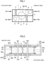
- An air treatment device (1) of this embodiment is configured as a dehumidifying/humidifying device, for example.
- the interior of the air treatment device (1) includes air passages (3) and (4) that are separated by a division wall (2).
- outdoor air (OA) taken from an outdoor space is supplied to an indoor space as supply air (SA) via the air passage (3)
- RA return air taken from the indoor space is discharged to the outdoor space as exhaust air (EA) via the air passage (4).
- An air conditioning rotating body (30) of this embodiment has a cylindrical rotor (10) made of a honeycomb-shaped adsorption element on which zeolite, for example, or another substance is supported, and a shaft (11) inserted in the center of the rotor (10).
- the shaft (11) is arranged on the boundary between the air passages (3) and (4).
- the air conditioning rotating body (30) is arranged over both of the air passages (3) and (4).
- the air passages (3) and (4) are each configured so that air flows in opposite directions and passes through the rotor (10) in its axial direction. Seal members (51), which separate the air passages (3) and (4) from each other, are slidably in contact with both axial end faces of the air conditioning rotating body (30).
- the rotor (10) is rotated to allow an adsorbent of the rotor (10) to adsorb water vapor from the air passing through the air passage (3), thereby generating dehumidified air.
- the adsorbent is regenerated by desorbing the water vapor from the adsorbent of the rotor (10) by air that is heated to a predetermined temperature and passes through the air passage (4).
- the heat exchanger (5) in the air passage (3) serves as an evaporator
- the heat exchanger (8) in the air passage (4) serves as a condenser.
- the rotor (10) is rotated to allow the adsorbent of the rotor (10) to adsorb water vapor from the air passing through the air passage (4).
- humidified air is generated, and the adsorbent is regenerated, by desorbing the water vapor from the adsorbent of the rotor (10) by air that is heated to a predetermined temperature and passes through the air passage (3).
- the heat exchanger (5) in the air passage (3) serves as a condenser
- the heat exchanger (8) in the air passage (4) serves as an evaporator.
- the upper plate (50a) and the lower plate (50b) are each provided with supports (57) made of resin, for example, for separating the intake port (52), (54) and the exhaust port (53), (55) from each other.
- the seal member (51) is held by being partially sandwiched between a side surface of the support (57) and a plate body (58).
- the supports (57) extend from the inner cylinder (21) of the protective case (20) in two directions opposite to each other by 180° along the radial direction. Sheet surfaces of the seal members (51) may be inclined with respect to the axial direction of the rotor (10) to allow for a margin in the contact area between the seal members (51) and each axial end face of the air conditioning rotating body (30).
- This configuration allows the sealing structure to be maintained more easily even in the event of axial displacement of an element, such as the rotor (10), compared to the case where the sheet surfaces of the seal members (51) are arranged perpendicularly along the axial direction of the rotor (10).
- the air conditioning rotating body (30) is housed in the casing (50) so as to be freely rotatable as illustrated in FIG. 7 .
- a motor (60) and a small gear (62) connected to a shaft (61) of the motor (60) are provided on the lower plate (50b) of the casing (50) near the air conditioning rotating body (30).
- the small gear (62) when rotated by the motor (60), drives and rotates the annular gear (24) on the side plate (22) covering the side surface on the outer circumference of the rotor (10), causing the air conditioning rotating body (30) to rotate.
- the shaft (11) of the air conditioning rotating body (30), i.e., the rotor (10), is fixed to, and supported by, the inner cylinder (21) of the protective case (20), and portions of the shaft (11) protruding from upper and lower ends of the inner cylinder (21) are rotatably held by bearing portions (12).
- a bearing support (13) is provided along the boundary between the intake port (52), (54) and the exhaust port (53), (55).
- the bearing portions (12) are attached to the respective bearing supports (13).
- the supports (57) holding the seal members (51) are attached to a surface of the bearing support (13) facing the air conditioning rotating body (30).
- annular support (59) made of resin, for example, is provided at each of the peripheral portion of the exhaust port (53) and the intake port (54) of the upper plate (50a) and the peripheral portion of the intake port (52) and the exhaust port (55) of the lower plate (50b).
- the casing-side seal (56) is attached to a surface of the annular support (59) facing the air conditioning rotating body (30).
- the end face of the support (57) on the outer circumference side of the rotor (10) is connected to an inner circumferential surface of annular support (59).
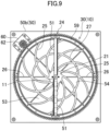
- FIG. 8 is a plan view of the air conditioning rotating body (30) viewed from above in the axial direction of the rotor (10) with the upper plate (50a) of the casing (50) removed.
- a structure (such as the supports (57)) for holding the seal members (51) is omitted.
- the spokes (25) of a thickness of, for example, about 1 mm to 2 mm is provided as an elevation on each axial end face of the rotor (10) to make the seal members (51) in contact with the spokes (25), thereby preventing the seal members (51) from making direct contact with the rotor (10). Wear of the rotor (10) can thus be reduced. Wear of the seal members (51), which come into contact with the spokes (25) when the air conditioning rotating body (30) rotates, can be further reduced by using, as the material for the spokes (25), a material having superior sliding properties to the material for the rotor (10).
- the thickness of each spoke (25) is preferably about 3 mm or less, more preferably about 1.5 mm or less.
- the shape of the spokes (25) (shape viewed from the axial direction of the rotor (10)) is set so that the contact points (indicated by the dashed circles in FIG. 8 ) of the seal member (51) extending in the radial direction of the rotor (10) with the spokes (25) move in the radial direction as the rotor (10) rotates.
- the spokes (25) are each formed into an arc shape curving in the circumferential direction of the rotor (10), as illustrated in FIG.
- the contact points of the spokes (25) with the seal member (51) move on the arc-shaped spokes (25) from the radially inside to the radially outside of the rotor (10) as the rotor (10) rotates.
- the solid arrows show the traj ectories of the moving contact points between the spokes (25) and the seal member (51) when the air conditioning rotating body (30) rotates counterclockwise as viewed from above in the axial direction of the rotor (10). Looking at the seal member (51), the contact points with the spokes (25) move in the radial direction as the rotor (10) rotates.
- the shape of the spokes (25) is not limited as long as the spokes (25) each have a portion that extends diagonally with respect to the radial direction of the rotor (10).
- the spokes (25) may be arc-shaped, or S-shaped or zigzag-shaped, for example.
- the seal member (51) may be in contact with a plurality of spokes (25) at any rotational position of the air conditioning rotating body (30).
- the seal member (51) corresponding to the radius of the rotor (10) is in contact with the three spokes (25).
- both of the axial end faces of the rotor (10) may be provided with the reinforcing ribs (26) extending in the radial direction. At least part of each reinforcing rib (26) may be fitted into the axial end faces of the rotor (10) by, for example, about 1 cm.
- the reinforcing rib (26) may be connected to one spoke (25) or a plurality of spokes (25).
- the reinforcing rib (26) and the spoke (25) may have end faces, in the axial direction of the rotor (10), which are flush with each other, or the end face of the reinforcing rib (26) may be lower than the end face of the spoke (25). In the latter case, the contact between the reinforcing rib (26) and the seal member (51) is reduced, thereby making it possible to reduce wear of the seal member (51).
- the contact points between the spokes (25) on the axial end faces of the rotor (10) and the seal member (51) that separates the air passages move in the radial direction as the rotor (10) rotates. It is therefore possible to reduce air leakage due to local progress of wear caused by concentration of loads on a specific portion of the seal member (51). Further, the frequency of replacement of the seal member (51) due to wear of the seal member (51) can be reduced, thereby preventing an increase in cost and a decrease in operating rate.
- the seal member (51) may be in contact with a plurality of spokes (25). This means that the seal member (51) is supported by the spokes (25) at multiple points.
- the load on the seal member (51) is equal to a force that makes the seal member (51) deformed by the contact with the spokes (25) return to its original shape.
- supporting the seal member (51) by the spokes (25) at multiple points spreads the load per contact point on the seal member (51). Since the amount of wear of the seal member (51) is proportional to the load on the seal member (51), the structure of supporting the seal member (51) by the spokes (25) at multiple points can further reduce local wear of the seal member (51).
- edges of the seal members are brought into contact with the case of the rotor all the time, and loads are concentrated on the edges; therefore, wear of the edges of the seal members progresses.
- the spoke (25) may have a curved shape that curves in the circumferential direction of the rotor (10).
- the support point for the seal member (51) is movable in the radial direction of the rotor (10) as the rotor (10) rotates. Wear of the seal member (51) can thus be reduced.
- the axial end faces of the rotor (10) may be provided with the reinforcing rib (26) extending in the radial direction (i.e., the linear reinforcing rib (26)).
- This configuration can reinforce the support structure for the rotor (10) and reduce warpage of the rotor (10).
- An increase in gap between the rotor (10) and the seal member (51) can thus be reduced, making it possible to reduce air leakage.
- the air treatment device (1) of this embodiment includes the air conditioning rotating body (30) that can reduce air leakage caused by wear of the seal member (51) separating the air passages (3) and (4). This can improve the performance of the air treatment device (1), such as dehumidification and humidification performance and heat exchange performance.
- the first variation differs from the above embodiment in that, as illustrated in FIG. 9 , the axial end face of the rotor (10) is provided with an annular member (27) surrounding the center of the rotor (10) circumferentially, specifically a true-circular member concentric with the rotor (10).
- annular member (27) surrounding the center of the rotor (10) circumferentially, specifically a true-circular member concentric with the rotor (10).
- the following effects can be obtained in addition to the effects similar to those of the above-described embodiment. That is, the arrangement of the annular member (27) increases the number of support points for the seal member (51), spreading the load per support point on the seal member (51). Local wear of the seal member (51) can thus be further reduced. Connecting the annular member (27) with the spokes (25) can reinforce the spokes (25).
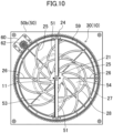
- a true-circular member concentric with the rotor (10) is provided as the annular member (27) in the above first variation, as illustrated in FIG. 9 .
- an oval member with a focal point at the center of the rotor (10) is provided as an annular member (28) in the second variation, as illustrated in FIG. 10 .
- the same reference characters are used to designate the same elements as those in the first variation illustrated in FIG. 9 .
- the annular member (27) illustrated in FIG. 9 is indicated by broken curves.
- the following effects can be obtained in addition to the effects similar to those of the above-described first variation. That is, according to the configuration of the second variation, local wear of the seal member (51) can be reduced more than in the configuration of the first variation, because the contact points of the seal member (51) with the annular member (28) move in the radial direction of the rotor (10) as the rotor (10) rotates. In this case, it is more preferable to make the width of the annular member (28) in the radial direction of the rotor (10) smaller than the distance of movement of the contact point of the seal member (51) with the annular member (28).
- the spokes (25) are provided on each of both axial end faces of the rotor (10), and the spokes (25) provided on both of the end faces are arranged to overlap each other when viewed from the axial direction of the rotor (10).
- the diagram (a) illustrates a planar configuration of the protective case (20) including the shaft (11), as viewed from one side in the axial direction of the rotor (10); the diagram (b) illustrates a side configuration of the protective case (20) including the shaft (11), as viewed from the radial direction of the rotor (10); and the diagram (c) illustrates a planar configuration of the protective case (20) including the shaft (11), as viewed from the other side in the axial direction of the rotor (10).
- the same reference characters are used to designate the same elements as those in the embodiment illustrated in FIG. 8 .
- the protective case (20) is not provided with the reinforcing ribs (26), but provided with an annular member (27) similar to that in the first variation.
- the annular members (27) provided on both of the axial end faces of the rotor (10) are arranged to overlap each other when viewed from the axial direction of the rotor (10).
- the spokes (25) and other parts are arranged in mirror symmetry on both axial end faces of the rotor (10).
- the air that has flowed into the rotor (10) through open regions on one side in the axial direction of the rotor (10) flows out through open regions on the other side in the axial direction of the rotor (10) without colliding with non-opening regions on the other side.
- the substantial opening area is therefore increased on both sides in the axial direction of the rotor (10), making it possible to improve the air conditioning capacity.
- the reinforcing ribs (26) may be arranged on both of the axial end faces of the rotor (10) so as to overlap each other when viewed from the axial direction of the rotor (10).
- the protective case (20) does not have to include the annular members (27).
- the annular members (28) similar to that of the second variation may be arranged on both of the axial end faces of the rotor (10), instead of the annular members (27), so as to overlap each other when viewed from the axial direction of the rotor (10).
- the air treatment device (1) is configured as a dehumidifying/humidifying device, by using, as the rotor (10) of the air conditioning rotating body (30), a honeycomb-shaped adsorption element on which zeolite is supported.
- the air treatment device (1) may be configured as a deodorizer, a gas separator, or the like, by using an air conditioning rotating body with a rotor that is a honeycomb-shaped adsorption element on which another adsorbent, such as porous silica or activated alumina, is supported.
- the air treatment device (1) may be configured as a heat exchanger, by using an air conditioning rotating body with a rotor made of a material with excellent heat storage properties, such as aluminum or stainless steel.
- the air conditioning rotating body (30) is arranged in the air treatment device (1) such that the radial direction of the rotor (10) is along the horizontal direction.
- the air conditioning rotating body (30) may be arranged in the air treatment device (1) such that the radial direction of the rotor (10) is along the perpendicular (vertical) direction.
- the two air passages (3) and (4) are formed in the air treatment device (1), and the air conditioning rotating body (30) is arranged over both of the air passages (3) and (4).
- the number of air passages in the air treatment device (1) i.e., the number of air passages where the air conditioning rotating body (30) is arranged
- the number of air passages in the air treatment device (1) is not particularly limited, and may be three or more.
- the present disclosure is useful for an air conditioning rotating body and an air treatment device.
Landscapes
- Chemical & Material Sciences (AREA)
- Engineering & Computer Science (AREA)
- General Chemical & Material Sciences (AREA)
- Chemical Kinetics & Catalysis (AREA)
- Oil, Petroleum & Natural Gas (AREA)
- Analytical Chemistry (AREA)
- Mechanical Engineering (AREA)
- General Engineering & Computer Science (AREA)
- Combustion & Propulsion (AREA)
- Central Air Conditioning (AREA)
- Drying Of Gases (AREA)
- Disinfection, Sterilisation Or Deodorisation Of Air (AREA)
- Separation Of Gases By Adsorption (AREA)
Claims (7)
- Klimaanlagendrehkörper (30) mit einem Rotor (10) in einer zylindrischen Form, wobei der Rotor (10) in einem Gehäuse (50) untergebracht ist, um frei drehbar zu sein, wobei der Klimaanlagendrehkörper (30) konfiguriert ist, um Luft zu behandeln, die durch den Rotor (10) in einer axialen Richtung hindurchgeht, wobeidas Gehäuse (50) ein Dichtungselement (51) beinhaltet, das sich in einer radialen Richtung des Rotors (10) erstreckt und Luftdurchlässe trennt, undeine Endfläche des Rotors (10) in der axialen Richtung mit mindestens einer Speiche (25) in Kontakt mit dem Dichtungselement (51) versehen ist,dadurch gekennzeichnet, dasssich ein Kontaktpunkt des Dichtungselements (51) mit der Speiche (25) in der radialen Richtung bewegt, wenn sich der Rotor (10) dreht.
- Klimaanlagendrehkörper nach Anspruch 1, wobei
das Dichtungselement (51) mit einer Vielzahl der Speichen (25) in Kontakt gebracht ist. - Klimaanlagendrehkörper nach Anspruch 1 oder 2, wobei die Speiche (25) in einer Umfangsrichtung des Rotors (10) gekrümmt ist.
- Klimaanlagendrehkörper nach einem der Ansprüche 1 bis 3, wobei die Endfläche des Rotors (10) ferner mit einer Verstärkungsrippe (26) versehen ist, die sich in der radialen Richtung erstreckt.
- Klimaanlagendrehkörper nach einem der Ansprüche 1 bis 4, wobei
die Endfläche des Rotors (10) ferner mit einem ringförmigen Element (27, 28) versehen ist, das eine Mitte des Rotors (10) in Umfangsrichtung umgibt. - Klimaanlagendrehkörper nach einem der Ansprüche 1 bis 5, wobei
die Speiche (25) an jeder von beiden Endflächen des Rotors (10) in der axialen Richtung vorgesehen ist und die Speichen (25), die an beiden Endflächen vorgesehen sind, einander überlappen, wenn sie aus der axialen Richtung betrachtet werden. - Luftbehandlungsvorrichtung, die den Klimaanlagendrehkörper (30) nach einem der Ansprüche 1 bis 6 umfasst, wobeidas Innere der Luftbehandlungsvorrichtung (1) Luftdurchlässe (3) und (4) beinhaltet, die durch eine Trennwand (2) getrennt sind, undder Klimaanlagendrehkörper (30) über beiden der Luftdurchlässe (3) und (4) angeordnet ist.
Applications Claiming Priority (2)
| Application Number | Priority Date | Filing Date | Title |
|---|---|---|---|
| JP2020134347A JP7041373B2 (ja) | 2020-08-07 | 2020-08-07 | 空調回転体及び空気処理装置 |
| PCT/JP2021/018563 WO2022030066A1 (ja) | 2020-08-07 | 2021-05-17 | 空調回転体及び空気処理装置 |
Publications (3)
| Publication Number | Publication Date |
|---|---|
| EP4154969A1 EP4154969A1 (de) | 2023-03-29 |
| EP4154969A4 EP4154969A4 (de) | 2023-11-15 |
| EP4154969B1 true EP4154969B1 (de) | 2024-09-11 |
Family
ID=80117847
Family Applications (1)
| Application Number | Title | Priority Date | Filing Date |
|---|---|---|---|
| EP21853887.4A Active EP4154969B1 (de) | 2020-08-07 | 2021-05-17 | Klimaanlagendrehkörper und luftbehandlungsvorrichtung |
Country Status (5)
| Country | Link |
|---|---|
| US (1) | US12453940B2 (de) |
| EP (1) | EP4154969B1 (de) |
| JP (1) | JP7041373B2 (de) |
| CN (1) | CN116096476A (de) |
| WO (1) | WO2022030066A1 (de) |
Families Citing this family (8)
| Publication number | Priority date | Publication date | Assignee | Title |
|---|---|---|---|---|
| JP2023053433A (ja) * | 2021-10-01 | 2023-04-13 | パナソニックIpマネジメント株式会社 | 空気調和機 |
| JP2023158284A (ja) * | 2022-04-18 | 2023-10-30 | 株式会社西部技研 | 吸着ロータ及びその収納装置 |
| JP2024092329A (ja) * | 2022-12-26 | 2024-07-08 | クボタ空調株式会社 | デシカントロータおよびデシカントカセット |
| SE2351020A1 (en) * | 2023-08-31 | 2025-03-01 | Munters Europe Ab | Air treatment unit and method for manufacturing such air treatment unit |
| WO2025180615A1 (en) * | 2024-02-28 | 2025-09-04 | Robert Bosch Gmbh | Method and system for controlling a direct air capture system for use with a heating, ventilation and/or air conditioning system |
| WO2025180614A1 (en) * | 2024-02-28 | 2025-09-04 | Robert Bosch Gmbh | Direct air capture module for use with a heating, ventilation and/or air conditioning system |
| WO2025180617A1 (en) * | 2024-02-28 | 2025-09-04 | Robert Bosch Gmbh | Direct air capture module for use with a heating, ventilation and/or air conditioning system |
| WO2025180620A1 (en) * | 2024-02-28 | 2025-09-04 | Robert Bosch Gmbh | Air management system comprising a direct air capture module and method of controlling the air management system |
Family Cites Families (18)
| Publication number | Priority date | Publication date | Assignee | Title |
|---|---|---|---|---|
| US4432409A (en) * | 1981-11-03 | 1984-02-21 | Northern Solar Systems, Inc. | Rotary heat regenerator wheel and method of manufacture thereof |
| US4875520A (en) * | 1985-10-22 | 1989-10-24 | Airxchange, Inc. | Desiccant heat device |
| US4924934A (en) * | 1988-03-14 | 1990-05-15 | Airxchange, Inc. | Rotary heat wheel cassette assembly |
| US5595238A (en) * | 1994-09-16 | 1997-01-21 | Engelhard/Icc | Rotatably supported regenerative fluid treatment wheel assemblies |
| US5878590A (en) * | 1998-02-25 | 1999-03-09 | General Motors Corporation | Dehumidifying mechanism for auto air conditioner with improved space utilization and thermal efficiency |
| JP3755708B2 (ja) | 1998-07-08 | 2006-03-15 | 株式会社西部技研 | ガス吸着素子およびガス吸着装置 |
| US6684649B1 (en) * | 1999-11-05 | 2004-02-03 | David A. Thompson | Enthalpy pump |
| US20030056884A1 (en) * | 2001-09-26 | 2003-03-27 | Belding William A. | Heat and moisture exchange media |
| JP3482409B1 (ja) * | 2002-05-30 | 2003-12-22 | 東京エレクトロン株式会社 | 減湿装置及び減湿方法 |
| KR20050057144A (ko) * | 2002-09-20 | 2005-06-16 | 동경 엘렉트론 주식회사 | 건조공기 공급장치 및 처리장치 |
| JP3896343B2 (ja) | 2003-04-25 | 2007-03-22 | 東京エレクトロン株式会社 | 乾燥空気供給装置 |
| US8313569B2 (en) | 2006-11-20 | 2012-11-20 | Winiamando Inc. | Air washer having humidifying function |
| EP2332631B1 (de) * | 2009-12-03 | 2012-11-14 | Kaeser Kompressoren GmbH | Adsorptionstrocknungsvorrichtung sowie Adsorptionstrocknungsverfahren |
| CN202083055U (zh) | 2011-05-17 | 2011-12-21 | 宁波真和电器股份有限公司 | 一种空气净化加湿装置 |
| WO2015119736A1 (en) * | 2014-02-04 | 2015-08-13 | Carrier Corporation | Hard interface dynamic seals |
| JP6385781B2 (ja) * | 2014-10-06 | 2018-09-05 | シャープ株式会社 | 除湿装置 |
| KR102384474B1 (ko) | 2015-06-19 | 2022-04-08 | 삼성전자주식회사 | 기화식 가습기 |
| JP7148815B2 (ja) * | 2020-08-07 | 2022-10-06 | ダイキン工業株式会社 | 空調回転体及び空気処理装置 |
-
2020
- 2020-08-07 JP JP2020134347A patent/JP7041373B2/ja active Active
-
2021
- 2021-05-17 CN CN202180057262.XA patent/CN116096476A/zh active Pending
- 2021-05-17 WO PCT/JP2021/018563 patent/WO2022030066A1/ja not_active Ceased
- 2021-05-17 EP EP21853887.4A patent/EP4154969B1/de active Active
-
2023
- 2023-01-31 US US18/103,920 patent/US12453940B2/en active Active
Also Published As
| Publication number | Publication date |
|---|---|
| US20230173429A1 (en) | 2023-06-08 |
| CN116096476A (zh) | 2023-05-09 |
| WO2022030066A1 (ja) | 2022-02-10 |
| JP7041373B2 (ja) | 2022-03-24 |
| EP4154969A4 (de) | 2023-11-15 |
| JP2022030364A (ja) | 2022-02-18 |
| US12453940B2 (en) | 2025-10-28 |
| EP4154969A1 (de) | 2023-03-29 |
Similar Documents
| Publication | Publication Date | Title |
|---|---|---|
| EP4154969B1 (de) | Klimaanlagendrehkörper und luftbehandlungsvorrichtung | |
| JP6578486B2 (ja) | 除湿装置 | |
| US20150362202A1 (en) | Air conditioning device | |
| JP7566169B2 (ja) | 空気調和設備 | |
| US20230167906A1 (en) | Air conditioning rotating body and air treatment device | |
| KR100675801B1 (ko) | 제가습 장치 | |
| JP2005095807A (ja) | 除湿機 | |
| JP2000237524A (ja) | 乾式減湿システム | |
| JP5898513B2 (ja) | デシカント式換気扇用ローター枠 | |
| JP4682667B2 (ja) | 調湿装置 | |
| JP4706303B2 (ja) | 調湿装置 | |
| EP1598601A2 (de) | Anordnung zum Regeln von Feuchte mittels flüssigen Trocknungsmittels | |
| JP6956311B2 (ja) | 除湿装置 | |
| JP7837263B2 (ja) | 調湿装置及び住宅 | |
| EP4368909A1 (de) | Lüftungsgerät | |
| KR20200081111A (ko) | 제습로터 및 이에 연결되는 송풍기와 열교환기의 조립 구조 | |
| CN113091164B (zh) | 除湿用转子以及除湿机 | |
| JP7807936B2 (ja) | 調湿装置及び住宅 | |
| JP2014089029A (ja) | 加湿装置および換気扇 | |
| JP2007101055A (ja) | 加湿ユニット、および空気調和機の室外機 | |
| JP5356783B2 (ja) | 除湿ロータの外周シール構造 | |
| JP2003065560A (ja) | 調湿機 | |
| JP2002119823A (ja) | 調湿機 | |
| CN120332852A (zh) | 一种湿度调节装置 | |
| JP2024060974A (ja) | 調湿装置及び住宅 |
Legal Events
| Date | Code | Title | Description |
|---|---|---|---|
| STAA | Information on the status of an ep patent application or granted ep patent |
Free format text: STATUS: THE INTERNATIONAL PUBLICATION HAS BEEN MADE |
|
| PUAI | Public reference made under article 153(3) epc to a published international application that has entered the european phase |
Free format text: ORIGINAL CODE: 0009012 |
|
| STAA | Information on the status of an ep patent application or granted ep patent |
Free format text: STATUS: REQUEST FOR EXAMINATION WAS MADE |
|
| 17P | Request for examination filed |
Effective date: 20221221 |
|
| AK | Designated contracting states |
Kind code of ref document: A1 Designated state(s): AL AT BE BG CH CY CZ DE DK EE ES FI FR GB GR HR HU IE IS IT LI LT LU LV MC MK MT NL NO PL PT RO RS SE SI SK SM TR |
|
| P01 | Opt-out of the competence of the unified patent court (upc) registered |
Effective date: 20230525 |
|
| A4 | Supplementary search report drawn up and despatched |
Effective date: 20231018 |
|
| DAV | Request for validation of the european patent (deleted) | ||
| DAX | Request for extension of the european patent (deleted) | ||
| RIC1 | Information provided on ipc code assigned before grant |
Ipc: B01D 53/06 20060101ALI20231012BHEP Ipc: F24F 3/14 20060101ALI20231012BHEP Ipc: A61L 9/014 20060101ALI20231012BHEP Ipc: B01D 53/26 20060101AFI20231012BHEP |
|
| GRAP | Despatch of communication of intention to grant a patent |
Free format text: ORIGINAL CODE: EPIDOSNIGR1 |
|
| STAA | Information on the status of an ep patent application or granted ep patent |
Free format text: STATUS: GRANT OF PATENT IS INTENDED |
|
| RIC1 | Information provided on ipc code assigned before grant |
Ipc: B01D 53/06 20060101ALI20240620BHEP Ipc: F24F 3/14 20060101ALI20240620BHEP Ipc: A61L 9/014 20060101ALI20240620BHEP Ipc: B01D 53/26 20060101AFI20240620BHEP |
|
| GRAS | Grant fee paid |
Free format text: ORIGINAL CODE: EPIDOSNIGR3 |
|
| INTG | Intention to grant announced |
Effective date: 20240709 |
|
| RIN1 | Information on inventor provided before grant (corrected) |
Inventor name: TANAKA, HIDEKAZU Inventor name: OKUBO, EISAKU Inventor name: TAKAHASHI, TAKASHI Inventor name: OHDOU, TSUNAHIRO |
|
| GRAA | (expected) grant |
Free format text: ORIGINAL CODE: 0009210 |
|
| STAA | Information on the status of an ep patent application or granted ep patent |
Free format text: STATUS: THE PATENT HAS BEEN GRANTED |
|
| AK | Designated contracting states |
Kind code of ref document: B1 Designated state(s): AL AT BE BG CH CY CZ DE DK EE ES FI FR GB GR HR HU IE IS IT LI LT LU LV MC MK MT NL NO PL PT RO RS SE SI SK SM TR |
|
| REG | Reference to a national code |
Ref country code: GB Ref legal event code: FG4D |
|
| REG | Reference to a national code |
Ref country code: CH Ref legal event code: EP |
|
| REG | Reference to a national code |
Ref country code: DE Ref legal event code: R096 Ref document number: 602021018797 Country of ref document: DE |
|
| REG | Reference to a national code |
Ref country code: IE Ref legal event code: FG4D |
|
| REG | Reference to a national code |
Ref country code: LT Ref legal event code: MG9D |
|
| PG25 | Lapsed in a contracting state [announced via postgrant information from national office to epo] |
Ref country code: NO Free format text: LAPSE BECAUSE OF FAILURE TO SUBMIT A TRANSLATION OF THE DESCRIPTION OR TO PAY THE FEE WITHIN THE PRESCRIBED TIME-LIMIT Effective date: 20241211 |
|
| REG | Reference to a national code |
Ref country code: NL Ref legal event code: MP Effective date: 20240911 |
|
| PG25 | Lapsed in a contracting state [announced via postgrant information from national office to epo] |
Ref country code: GR Free format text: LAPSE BECAUSE OF FAILURE TO SUBMIT A TRANSLATION OF THE DESCRIPTION OR TO PAY THE FEE WITHIN THE PRESCRIBED TIME-LIMIT Effective date: 20241212 Ref country code: FI Free format text: LAPSE BECAUSE OF FAILURE TO SUBMIT A TRANSLATION OF THE DESCRIPTION OR TO PAY THE FEE WITHIN THE PRESCRIBED TIME-LIMIT Effective date: 20240911 |
|
| PG25 | Lapsed in a contracting state [announced via postgrant information from national office to epo] |
Ref country code: BG Free format text: LAPSE BECAUSE OF FAILURE TO SUBMIT A TRANSLATION OF THE DESCRIPTION OR TO PAY THE FEE WITHIN THE PRESCRIBED TIME-LIMIT Effective date: 20240911 |
|
| PG25 | Lapsed in a contracting state [announced via postgrant information from national office to epo] |
Ref country code: LV Free format text: LAPSE BECAUSE OF FAILURE TO SUBMIT A TRANSLATION OF THE DESCRIPTION OR TO PAY THE FEE WITHIN THE PRESCRIBED TIME-LIMIT Effective date: 20240911 |
|
| PG25 | Lapsed in a contracting state [announced via postgrant information from national office to epo] |
Ref country code: HR Free format text: LAPSE BECAUSE OF FAILURE TO SUBMIT A TRANSLATION OF THE DESCRIPTION OR TO PAY THE FEE WITHIN THE PRESCRIBED TIME-LIMIT Effective date: 20240911 |
|
| PG25 | Lapsed in a contracting state [announced via postgrant information from national office to epo] |
Ref country code: ES Free format text: LAPSE BECAUSE OF FAILURE TO SUBMIT A TRANSLATION OF THE DESCRIPTION OR TO PAY THE FEE WITHIN THE PRESCRIBED TIME-LIMIT Effective date: 20240911 Ref country code: RS Free format text: LAPSE BECAUSE OF FAILURE TO SUBMIT A TRANSLATION OF THE DESCRIPTION OR TO PAY THE FEE WITHIN THE PRESCRIBED TIME-LIMIT Effective date: 20241211 |
|
| PG25 | Lapsed in a contracting state [announced via postgrant information from national office to epo] |
Ref country code: RS Free format text: LAPSE BECAUSE OF FAILURE TO SUBMIT A TRANSLATION OF THE DESCRIPTION OR TO PAY THE FEE WITHIN THE PRESCRIBED TIME-LIMIT Effective date: 20241211 Ref country code: NO Free format text: LAPSE BECAUSE OF FAILURE TO SUBMIT A TRANSLATION OF THE DESCRIPTION OR TO PAY THE FEE WITHIN THE PRESCRIBED TIME-LIMIT Effective date: 20241211 Ref country code: LV Free format text: LAPSE BECAUSE OF FAILURE TO SUBMIT A TRANSLATION OF THE DESCRIPTION OR TO PAY THE FEE WITHIN THE PRESCRIBED TIME-LIMIT Effective date: 20240911 Ref country code: HR Free format text: LAPSE BECAUSE OF FAILURE TO SUBMIT A TRANSLATION OF THE DESCRIPTION OR TO PAY THE FEE WITHIN THE PRESCRIBED TIME-LIMIT Effective date: 20240911 Ref country code: GR Free format text: LAPSE BECAUSE OF FAILURE TO SUBMIT A TRANSLATION OF THE DESCRIPTION OR TO PAY THE FEE WITHIN THE PRESCRIBED TIME-LIMIT Effective date: 20241212 Ref country code: FI Free format text: LAPSE BECAUSE OF FAILURE TO SUBMIT A TRANSLATION OF THE DESCRIPTION OR TO PAY THE FEE WITHIN THE PRESCRIBED TIME-LIMIT Effective date: 20240911 Ref country code: ES Free format text: LAPSE BECAUSE OF FAILURE TO SUBMIT A TRANSLATION OF THE DESCRIPTION OR TO PAY THE FEE WITHIN THE PRESCRIBED TIME-LIMIT Effective date: 20240911 Ref country code: BG Free format text: LAPSE BECAUSE OF FAILURE TO SUBMIT A TRANSLATION OF THE DESCRIPTION OR TO PAY THE FEE WITHIN THE PRESCRIBED TIME-LIMIT Effective date: 20240911 |
|
| REG | Reference to a national code |
Ref country code: AT Ref legal event code: MK05 Ref document number: 1722206 Country of ref document: AT Kind code of ref document: T Effective date: 20240911 |
|
| PG25 | Lapsed in a contracting state [announced via postgrant information from national office to epo] |
Ref country code: NL Free format text: LAPSE BECAUSE OF FAILURE TO SUBMIT A TRANSLATION OF THE DESCRIPTION OR TO PAY THE FEE WITHIN THE PRESCRIBED TIME-LIMIT Effective date: 20240911 |
|
| PG25 | Lapsed in a contracting state [announced via postgrant information from national office to epo] |
Ref country code: IS Free format text: LAPSE BECAUSE OF FAILURE TO SUBMIT A TRANSLATION OF THE DESCRIPTION OR TO PAY THE FEE WITHIN THE PRESCRIBED TIME-LIMIT Effective date: 20250111 Ref country code: PT Free format text: LAPSE BECAUSE OF FAILURE TO SUBMIT A TRANSLATION OF THE DESCRIPTION OR TO PAY THE FEE WITHIN THE PRESCRIBED TIME-LIMIT Effective date: 20250113 |
|
| PG25 | Lapsed in a contracting state [announced via postgrant information from national office to epo] |
Ref country code: RO Free format text: LAPSE BECAUSE OF FAILURE TO SUBMIT A TRANSLATION OF THE DESCRIPTION OR TO PAY THE FEE WITHIN THE PRESCRIBED TIME-LIMIT Effective date: 20240911 Ref country code: SM Free format text: LAPSE BECAUSE OF FAILURE TO SUBMIT A TRANSLATION OF THE DESCRIPTION OR TO PAY THE FEE WITHIN THE PRESCRIBED TIME-LIMIT Effective date: 20240911 |
|
| PG25 | Lapsed in a contracting state [announced via postgrant information from national office to epo] |
Ref country code: EE Free format text: LAPSE BECAUSE OF FAILURE TO SUBMIT A TRANSLATION OF THE DESCRIPTION OR TO PAY THE FEE WITHIN THE PRESCRIBED TIME-LIMIT Effective date: 20240911 Ref country code: AT Free format text: LAPSE BECAUSE OF FAILURE TO SUBMIT A TRANSLATION OF THE DESCRIPTION OR TO PAY THE FEE WITHIN THE PRESCRIBED TIME-LIMIT Effective date: 20240911 |
|
| PG25 | Lapsed in a contracting state [announced via postgrant information from national office to epo] |
Ref country code: PL Free format text: LAPSE BECAUSE OF FAILURE TO SUBMIT A TRANSLATION OF THE DESCRIPTION OR TO PAY THE FEE WITHIN THE PRESCRIBED TIME-LIMIT Effective date: 20240911 Ref country code: CZ Free format text: LAPSE BECAUSE OF FAILURE TO SUBMIT A TRANSLATION OF THE DESCRIPTION OR TO PAY THE FEE WITHIN THE PRESCRIBED TIME-LIMIT Effective date: 20240911 |
|
| PG25 | Lapsed in a contracting state [announced via postgrant information from national office to epo] |
Ref country code: SK Free format text: LAPSE BECAUSE OF FAILURE TO SUBMIT A TRANSLATION OF THE DESCRIPTION OR TO PAY THE FEE WITHIN THE PRESCRIBED TIME-LIMIT Effective date: 20240911 Ref country code: IT Free format text: LAPSE BECAUSE OF FAILURE TO SUBMIT A TRANSLATION OF THE DESCRIPTION OR TO PAY THE FEE WITHIN THE PRESCRIBED TIME-LIMIT Effective date: 20240911 |
|
| REG | Reference to a national code |
Ref country code: DE Ref legal event code: R097 Ref document number: 602021018797 Country of ref document: DE |
|
| PGFP | Annual fee paid to national office [announced via postgrant information from national office to epo] |
Ref country code: DE Payment date: 20250521 Year of fee payment: 5 |
|
| PG25 | Lapsed in a contracting state [announced via postgrant information from national office to epo] |
Ref country code: DK Free format text: LAPSE BECAUSE OF FAILURE TO SUBMIT A TRANSLATION OF THE DESCRIPTION OR TO PAY THE FEE WITHIN THE PRESCRIBED TIME-LIMIT Effective date: 20240911 |
|
| PGFP | Annual fee paid to national office [announced via postgrant information from national office to epo] |
Ref country code: GB Payment date: 20250527 Year of fee payment: 5 |
|
| PGFP | Annual fee paid to national office [announced via postgrant information from national office to epo] |
Ref country code: FR Payment date: 20250528 Year of fee payment: 5 |
|
| PLBE | No opposition filed within time limit |
Free format text: ORIGINAL CODE: 0009261 |
|
| STAA | Information on the status of an ep patent application or granted ep patent |
Free format text: STATUS: NO OPPOSITION FILED WITHIN TIME LIMIT |
|
| 26N | No opposition filed |
Effective date: 20250612 |
|
| PG25 | Lapsed in a contracting state [announced via postgrant information from national office to epo] |
Ref country code: SE Free format text: LAPSE BECAUSE OF FAILURE TO SUBMIT A TRANSLATION OF THE DESCRIPTION OR TO PAY THE FEE WITHIN THE PRESCRIBED TIME-LIMIT Effective date: 20240911 |
|
| REG | Reference to a national code |
Ref country code: CH Ref legal event code: H13 Free format text: ST27 STATUS EVENT CODE: U-0-0-H10-H13 (AS PROVIDED BY THE NATIONAL OFFICE) Effective date: 20251223 |
|
| PG25 | Lapsed in a contracting state [announced via postgrant information from national office to epo] |
Ref country code: LU Free format text: LAPSE BECAUSE OF NON-PAYMENT OF DUE FEES Effective date: 20250517 |
|
| PG25 | Lapsed in a contracting state [announced via postgrant information from national office to epo] |
Ref country code: CH Free format text: LAPSE BECAUSE OF NON-PAYMENT OF DUE FEES Effective date: 20250531 |
|
| REG | Reference to a national code |
Ref country code: BE Ref legal event code: MM Effective date: 20250531 |
|
| PG25 | Lapsed in a contracting state [announced via postgrant information from national office to epo] |
Ref country code: MC Free format text: LAPSE BECAUSE OF FAILURE TO SUBMIT A TRANSLATION OF THE DESCRIPTION OR TO PAY THE FEE WITHIN THE PRESCRIBED TIME-LIMIT Effective date: 20240911 |