EP4154948B1 - Pad-struktur - Google Patents
Pad-struktur Download PDFInfo
- Publication number
- EP4154948B1 EP4154948B1 EP22196908.2A EP22196908A EP4154948B1 EP 4154948 B1 EP4154948 B1 EP 4154948B1 EP 22196908 A EP22196908 A EP 22196908A EP 4154948 B1 EP4154948 B1 EP 4154948B1
- Authority
- EP
- European Patent Office
- Prior art keywords
- slider
- string
- racket
- shape
- junction
- Prior art date
- Legal status (The legal status is an assumption and is not a legal conclusion. Google has not performed a legal analysis and makes no representation as to the accuracy of the status listed.)
- Active
Links
Images


Classifications
-
- A—HUMAN NECESSITIES
- A63—SPORTS; GAMES; AMUSEMENTS
- A63B—APPARATUS FOR PHYSICAL TRAINING, GYMNASTICS, SWIMMING, CLIMBING, OR FENCING; BALL GAMES; TRAINING EQUIPMENT
- A63B51/00—Stringing tennis, badminton or like rackets; Strings therefor; Maintenance of racket strings
- A63B51/12—Devices arranged in or on the racket for adjusting the tension of the strings
-
- A—HUMAN NECESSITIES
- A63—SPORTS; GAMES; AMUSEMENTS
- A63B—APPARATUS FOR PHYSICAL TRAINING, GYMNASTICS, SWIMMING, CLIMBING, OR FENCING; BALL GAMES; TRAINING EQUIPMENT
- A63B51/00—Stringing tennis, badminton or like rackets; Strings therefor; Maintenance of racket strings
-
- A—HUMAN NECESSITIES
- A63—SPORTS; GAMES; AMUSEMENTS
- A63B—APPARATUS FOR PHYSICAL TRAINING, GYMNASTICS, SWIMMING, CLIMBING, OR FENCING; BALL GAMES; TRAINING EQUIPMENT
- A63B49/00—Stringed rackets, e.g. for tennis
- A63B49/02—Frames
- A63B49/14—Protection devices on the frame
-
- A—HUMAN NECESSITIES
- A63—SPORTS; GAMES; AMUSEMENTS
- A63B—APPARATUS FOR PHYSICAL TRAINING, GYMNASTICS, SWIMMING, CLIMBING, OR FENCING; BALL GAMES; TRAINING EQUIPMENT
- A63B49/00—Stringed rackets, e.g. for tennis
- A63B49/02—Frames
-
- A—HUMAN NECESSITIES
- A63—SPORTS; GAMES; AMUSEMENTS
- A63B—APPARATUS FOR PHYSICAL TRAINING, GYMNASTICS, SWIMMING, CLIMBING, OR FENCING; BALL GAMES; TRAINING EQUIPMENT
- A63B60/00—Details or accessories of golf clubs, bats, rackets or the like
- A63B60/54—Details or accessories of golf clubs, bats, rackets or the like with means for damping vibrations
-
- A—HUMAN NECESSITIES
- A63—SPORTS; GAMES; AMUSEMENTS
- A63B—APPARATUS FOR PHYSICAL TRAINING, GYMNASTICS, SWIMMING, CLIMBING, OR FENCING; BALL GAMES; TRAINING EQUIPMENT
- A63B2102/00—Application of clubs, bats, rackets or the like to the sporting activity ; particular sports involving the use of balls and clubs, bats, rackets, or the like
- A63B2102/02—Tennis
-
- A—HUMAN NECESSITIES
- A63—SPORTS; GAMES; AMUSEMENTS
- A63B—APPARATUS FOR PHYSICAL TRAINING, GYMNASTICS, SWIMMING, CLIMBING, OR FENCING; BALL GAMES; TRAINING EQUIPMENT
- A63B2102/00—Application of clubs, bats, rackets or the like to the sporting activity ; particular sports involving the use of balls and clubs, bats, rackets, or the like
- A63B2102/04—Badminton
-
- A—HUMAN NECESSITIES
- A63—SPORTS; GAMES; AMUSEMENTS
- A63B—APPARATUS FOR PHYSICAL TRAINING, GYMNASTICS, SWIMMING, CLIMBING, OR FENCING; BALL GAMES; TRAINING EQUIPMENT
- A63B2102/00—Application of clubs, bats, rackets or the like to the sporting activity ; particular sports involving the use of balls and clubs, bats, rackets, or the like
- A63B2102/06—Squash
-
- A—HUMAN NECESSITIES
- A63—SPORTS; GAMES; AMUSEMENTS
- A63B—APPARATUS FOR PHYSICAL TRAINING, GYMNASTICS, SWIMMING, CLIMBING, OR FENCING; BALL GAMES; TRAINING EQUIPMENT
- A63B2209/00—Characteristics of used materials
-
- A—HUMAN NECESSITIES
- A63—SPORTS; GAMES; AMUSEMENTS
- A63B—APPARATUS FOR PHYSICAL TRAINING, GYMNASTICS, SWIMMING, CLIMBING, OR FENCING; BALL GAMES; TRAINING EQUIPMENT
- A63B2225/00—Miscellaneous features of sport apparatus, devices or equipment
- A63B2225/09—Adjustable dimensions
Definitions
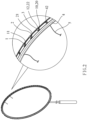
- the present disclosure relates to a racket and more particularly to racket with a pad structure that can filter out specific amplitude of a racket frame and a string or enhance or comply with specific (pound) Newton of force.
- rackets generally come with vertical and horizontal (X-axis and Y-axis) strings on their racket frame.
- the racket frames are mainly provided with substantially symmetrical vertical and horizontal threading holes around them, and the single nails are installed in the threading holes and the string is passed into the single nail and woven into a racket surface with a certain (pound) Newton of force, and the racket frame with string constitutes the racket provided for a very intense hitting sport such as tennis, badminton, racket ball, etc.
- the athlete holding the racket In order to catch the ball falling into the sweet spot of the racket, the athlete holding the racket not only needs to move quickly, but also needs to have continuity.
- the string of the racket frame and the ball produce shock waves at the moment of hitting, which will make the athlete's wrist and arm feel numb, wherein the anti-shock force is proportional to the (pound) Newton of force (i.e. tightness) of the string tension, and the higher the (pound) Newton of force, the greater the anti-vibration force, and the anti-vibration force will be transmitted along the racket to the wrist or arm which may easily cause sports injuries such as tennis elbow caused by backhand swings or golf elbow symptom caused by forehand swings.
- the invention is set out in the appended claims and refers to a racket comprising a racket frame and a pad structure as defined in claim 1.
- a secondary objective of this disclosure is to provide racket with a pad structure according to the appended claims that uses a first slider and a second slider to provide a string suspension or form a guide angle by the primary junction and the secondary junction, so that inclined planes can be used to move and dislocate relative to each other and to shift the string from the center to correct the specific amplitude.
- a further objective of this disclosure is to provide a racket with a pad structure according to the appended claims that can effectively improve the convenience of adjustment and use and filter out specific amplitude of the racket frame and string and enhance or comply with the specific (pound) Newton of force.
- the problem of the related art to be solved by this disclosure is the vibration and shock of the commonly used racket frame with a string.
- related manufacturers have developed devices to reduce the vibration and shock of the anti-vibration force generated by striking the racket surface composed of the ball and the string can be absorbed and buffered and transmitted to the athlete's wrist and arm completely to allow the racket to be held stably, and adjust the weight around the racket frame according to the athlete's needs, yet the specific amplitude of the string is fixed, and cannot be fine-tuned to filter out specific amplitudes of the racket frame and the string, and cannot enhance and comply with a specific (pound) Newton of force.
- the related art still has room for improvements.
- this disclosure provides a racket with a pad structure according to the appended claims, the pad structure applied to a damping device and a racket frame or a racket frame with a through hole and a string, and the through hole is provided with a single nail for passing a string, and the pad structure comprises:
- the first slider and the second slider are in a shape freely selected from the group consisting of a rectangular shape, a square shape or a combination thereof, and the primary junction of the first slider and the secondary junction of the second slider opposite to each other are substantially horizontal to the racket frame.
- the first slider and the second slider are in a shape freely selected from the group consisting of a triangular shape and a trapezium shape, or a combination of the above, and the primary junction of the first slider and the secondary junction of the second slider opposite to each other are tilted with an angle relative to the racket frame.
- the first slider or the second slider or an outer section of the first slider and the second slider is provided with a bore for passing the string and configured to be corresponsive to the through hole of the racket frame.
- the first slider or the second slider or an outer side of the first slider and the second slider is provided with a side recess and configured to be corresponsive the through hole of the racket frame and the string passing out from the through hole.
- the bore of the first slider and the bore of the second slider are in a shape including but not limited to the shape of a semicircular hole or a circular hole.
- the first slider or the second slider is in a trapezium shape and comprises a lower level portion disposed at a lower triangle of the first slider or a substrate portion disposed at a lower triangle of the second slider.
- the lower level portion is made of a hard material
- the substrate portion is made of a soft material or a hard material.
- first slider and the second slider are in a triangular shape, and an end of the first slider is configured to be corresponsive to the racket frame, and the other end of the second slider is provided with two vertical wall blocks and a string slot engaging with the string
- the other end of the primary junction at of the first slider is provided with two vertical lower wall blocks and has an embedding slot
- an end of the second slider is configured to be corresponsive to the secondary junction of the primary junction and provided with a guide bump perpendicular to the embedded slot and engaged with the embedding slot.
- this disclosure adopts the first slider or the second slider or the first slider and the second slider having the primary junction and the secondary junction, or having the lower wall blocks, the guide bumps and the wall blocks, so that the inclined planes can be used to move and dislocate relative to each other and to shift the string from the center to correct the specific amplitude.
- This disclosure effectively improves the convenience of adjustment and use, filters out specific amplitude of the racket frame 4 and the string 5, and enhances or complies with the specific (pound) Newton of force.
- This disclosure complies with the three patentability criteria, respectively: novelty, inventive step/non-obviousness and industrial applicability.
- FIGS. 1 to 14 for the exploded, perspective and cross-sectional views showing a first slider and a second slider in a trapezium shape
- the exploded and cross-sectional views showing the first slider of FIG. 4 having two lower wall blocks and the second slider having a guide bump
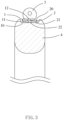
- a pad structure of a preferred embodiment is applied to a damping device 3 and a racket frame 4 or a racket frame 4 having a through hole 41 and a string 5, and the through hole 41 of the racket frame 4 has a single nail 42 provided for passing the string 5, and the pad structure includes at least one first slider 1 and at least one second slider 2.
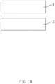
- the at least one first slider 1 has an end configured to be corresponsive to the bottom of the damping device 3 or the string 5 or the racket frame 4, and the other end having a primary junction 10 (as shown in FIGS. 1 to 3 and 10 to 14 , wherby fig. 10 is not forming part of the invention.)
- the at least one second slider 2 is installed at the other end of the first slider 1, and an end of the second slider 2 has a secondary junction 20 disposed opposite to the primary junction 10 of the first slider 1, and the other end of the second slider 2 is configured to be corresponsive to the racket frame 4 or the string 5 (as shown in FIGS. 1 to 3 and 10 to 14 .)
- the first slider 1 and the second slider 2 are provided for the suspension of the string 5, or the primary junction 10 and the secondary junction 20 form a guide angle for filtering out specific amplitude and enhance or comply with the specific (pound) Newton of force.
- the first slider 1 and the second slider 2 are in a shape freely selected from the group consisting of a rectangular shape, a square shape, a triangular shape, and any combination of the above, the primary junction 10 of the first slider 1 and the secondary junction 20 of the second slider 2 opposite to each other are substantially horizontal to the racket frame 4 (as shown in FIGS. 10 , 13 and 14 , whereby fig.
- the first slider 1 and the second slider 2 are in a shape freely selected from the group consisting of a triangular shape, a trapezium or any combination of the above, and the primary junction 10 of the first slider 1 and the secondary junction 20 of the second slider 2 opposite to each other are tilted with an angle relative to the racket frame 4 (as shown in FIGS. 1 to 9 and 11 to 12 );
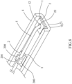
- the first slider 1 or the second slider 2 in the trapezium shape includes a lower level portion 11 disposed at a lower triangle of the first slider 1 or a substrate portion 21 disposed at a lower triangle of the second slider 2 (as shown in FIGS. 1 to 3 ), and the lower level portion 11 is made of a hard material, and the substrate portion 21 is made of a soft material or a hard material.
- the first slider 1 or the second slider 2 or the first slider 1 and the outer section of the second slider 2 have a bore 12, 22 separately provided for passing the string 5 and configured to be corresponsive to the through hole 41 of the racket frame 4, and the bore 12 of the first slider 1 and the bore 22 of the second slider 2 are in a shape including but not limited to the shape of a semicircular hole or a circular hole (as shown in FIGS. 1 to 3 and 8 ); and the first slider 1 or the second slider 2 or the outer edges of the first slider 1 and the second slider 2 of this disclosure are provided with a side recess 13, 23 which is configured to be corresponsive to the through hole 41 of the racket frame 4 and the string 5 passing out from the through hole 41 (as shown in FIG. 9 ).
- the first slider 1 and the second slider 2 are in a triangular shape, and the first slider 1 has an end corresponding to the racket frame 4 and another end having two vertical wall blocks 200 and a string slot 201 for sheathing the string 5 (as shown in FIGS. 4 and 5 ).
- the primary junction 10 at the other end of the first slider 1 has two vertical lower wall blocks 100 and an embedding slot 101, and an end of the second slider 2 is configured to be corresponsive to the secondary junction 20 of the primary junction 10 and provided with a guide bump 202 perpendicular the embedding slot 101 and embedded into the embedding slot 101 (as shown in FIGS. 6 and 7 ).
- This disclosure uses the first slider 1 or the second slider 2 or the first slider 1 and the second slider 2 having the primary junction 10 and the secondary junction 20 respectively, or having the lower wall block 100 and the guide bump 202 and the wall block 200 to achieve the effect of this disclosure and also uses the first slider 1 and the second slider 2 to provide the suspension of the string 5, or the primary junction 10 and the secondary junction 20 form a guide angle, so that the inclined planes can be used to move and dislocate relative to each other and to shift the string from the center to correct the specific amplitude.
- This disclosure effectively improves the convenience of adjustment and use, filters out specific amplitude of the racket frame 4 and the string 5, and enhances or complies with the specific (pound) Newton of force.
- This disclosure complies with the three patentability criteria, respectively: novelty, inventive step/non-obviousness and industrial applicability.
Landscapes
- Health & Medical Sciences (AREA)
- General Health & Medical Sciences (AREA)
- Physical Education & Sports Medicine (AREA)
- Buildings Adapted To Withstand Abnormal External Influences (AREA)
- Installation Of Indoor Wiring (AREA)
- Vibration Prevention Devices (AREA)
Claims (8)
- Schläger, umfassend einen Schlägerrahmen (4) und eine Kissenstruktur, wobei der Schläger eine Dämpfungsvorrichtung (3) und eine Saite (5) umfasst und die Kissenstruktur auf die Dämpfungsvorrichtung (3) aufgebracht ist oder wobei der Schläger einen einzigen Nagel (42) umfasst und der Schlägerrahmen (4) ein Durchgangsloch (41) umfasst und das Durchgangsloch (41) mit dem einzigen Nagel (42) versehen ist, um die Saite (5) hindurchzulassen,
wobei die Kissenstruktur Folgendes umfasst:mindestens einen ersten Schieber (1), der ein Ende, das dazu ausgestaltet ist, mit der Unterseite der Dämpfungsvorrichtung (3) oder der Saite (5) oder dem Schlägerrahmen (4) zusammenzupassen, und ein anderes Ende mit einer primären Verbindungsstelle (10) aufweist; undmindestens einen zweiten Schieber (2), der an dem anderen Ende des ersten Schiebers (1) angebracht ist und ein Ende mit einer sekundären Verbindungsstelle (20) gegenüber der primären Verbindungsstelle (10) des ersten Schiebers (1) und ein anderes Ende, das dazu ausgestaltet ist, mit dem Schlägerrahmen (4) oder der Saite (5) zusammenzupassen, aufweist;wobei der erste Schieber (1) und der zweite Schieber (2) eine Aufhängung der Saite (5) bereitstellen oder die primäre Verbindungsstelle (10) und die sekundäre Verbindungsstelle (20) einen Führungswinkel zum Herausfiltern einer spezifischen Amplitude bilden und ein spezifisches (Pound) Newton Kraft erhöhen oder diesem entsprechen,dadurch gekennzeichnet, dassder erste Schieber (1) und der zweite Schieber (2) in einer Form vorliegen, die frei aus der Gruppe bestehend aus einer dreieckigen Form und einer Trapezform odereiner Kombination davon ausgewählt ist, und die primäre Verbindungsstelle (10) des ersten Schiebers (1) und die sekundäre Verbindungsstelle (20) des zweiten Schiebers (2) gegenüber voneinander mit einem solchen Winkel in Bezug auf den Schlägerrahmen geneigt sind, dass geneigte Ebenen zum Bewegen und Verrücken in Bezug aufeinander und Verschieben der Saite (5) von der Mitte, um die spezifische Amplitude zu korrigieren, verwendet werden können,oderder eine der Schieber (1, 2) in einer Form vorliegt, die frei aus der Gruppe bestehend aus einer rechteckigen Form, einer quadratischen Form und einer dreieckigen Form oder einer Kombination davon ausgewählt ist und der andere der Schieber (2, 1) in Form einer dreieckigen Form vorliegt, und die primäre Verbindungsstelle (10) des ersten Schiebers (1) und die sekundäre Verbindungsstelle (20) des zweiten Schiebers (2) gegenüber voneinander im Wesentlichen horizontal zu dem Schlägerrahmen (4) verlaufen, sodass geneigte Ebenen zum Bewegen undVerrücken in Bezug aufeinander und zum Verschieben der Saite (5) von der Mitte, um die spezifische Amplitude zu korrigieren, verwendet werden können. - Schläger nach Anspruch 1, wobei der erste Schieber (1) oder der zweite Schieber (2) oder ein äußerer Abschnitt des ersten Schiebers (1) und des zweiten Schiebers (2) mit einer Bohrung (12, 22) zum Hindurchlassen der Saite (5) versehen und dazu ausgestaltet ist, mit dem Durchgangsloch (41) des Schlägerrahmens (4) zusammenzupassen.
- Schläger nach Anspruch 1, wobei der erste Schieber (1) oder der zweite Schieber (2) oder eine Außenseite des ersten Schiebers (1) und des zweiten Schiebers (2) mit einem Seitenvorsprung versehen und dazu ausgestaltet ist, mit dem Durchgangsloch (41) des Schlägerrahmens (4) und der Saite (5) zusammenzupassen, die aus dem Durchgangsloch (41) hinausgelassen wird.
- Schläger nach Anspruch 3, wobei die Bohrung (12) des ersten Schiebers (1) und die Bohrung (22) des zweiten Schiebers (2) in einer Form vorliegen, die die Form eines halbkreisförmigen Lochs oder eines kreisförmigen Lochs einschließt, ohne dass dies jedoch eine Einschränkung darstellt.
- Schläger nach Anspruch 1, wobei der erste Schieber (1) oder der zweite Schieber (2) in einer Trapezform vorliegt und einen Abschnitt auf unterer Ebene, der an einem unteren Dreieck des ersten Schiebers (1) angeordnet ist, oder einen Substratabschnitt, der an einem unteren Dreieck des zweiten Schiebers (2) angeordnet ist, umfasst.
- Schläger nach Anspruch 5, wobei der Abschnitt auf unterer Ebene aus einem harten Material gefertigt ist und der Substartabschnitt aus einem weichen Material oder einem harten Material gefertigt ist.
- Schläger nach Anspruch 1, wobei der erste Schieber (1) und der zweite Schieber (2) in dreieckiger Form vorliegen und ein Ende des ersten Schiebers (1) dazu ausgestaltet ist, mit dem Schlägerrahmen (4) zusammenzupassen, und das andere Ende des zweiten Schiebers (2) mit zwei vertikalen Wandblöcken und einem Saitenschlitz, der die Saite in Eingriff nimmt, versehen ist.
- Schläger nach Anspruch 7, wobei das andere Ende der primären Verbindungsstelle (10) des ersten Schiebers (1) mit zwei vertikalen unteren Wandblöcken versehen ist und einen einbettenden Schlitz aufweist und ein Ende des zweiten Schiebers (2) dazu ausgestaltet ist, mit der sekundären Verbindungsstelle (20) der primären Verbindungsstelle (10) zusammenzupassen und mit einem Führungshöcker, der senkrecht zu dem eingebetteten Schlitz verläuft und mit dem eingebetteten Schlitz in Eingriff steht, versehen ist.
Applications Claiming Priority (1)
| Application Number | Priority Date | Filing Date | Title |
|---|---|---|---|
| TW110136069A TWI830065B (zh) | 2021-09-28 | 2021-09-28 | 墊片結構 |
Publications (3)
| Publication Number | Publication Date |
|---|---|
| EP4154948A1 EP4154948A1 (de) | 2023-03-29 |
| EP4154948C0 EP4154948C0 (de) | 2024-09-11 |
| EP4154948B1 true EP4154948B1 (de) | 2024-09-11 |
Family
ID=83400807
Family Applications (1)
| Application Number | Title | Priority Date | Filing Date |
|---|---|---|---|
| EP22196908.2A Active EP4154948B1 (de) | 2021-09-28 | 2022-09-21 | Pad-struktur |
Country Status (7)
| Country | Link |
|---|---|
| US (1) | US20230099809A1 (de) |
| EP (1) | EP4154948B1 (de) |
| JP (1) | JP2023049022A (de) |
| KR (1) | KR20230045557A (de) |
| CN (1) | CN115382178A (de) |
| ES (1) | ES2989719T3 (de) |
| TW (1) | TWI830065B (de) |
Families Citing this family (2)
| Publication number | Priority date | Publication date | Assignee | Title |
|---|---|---|---|---|
| TWI814038B (zh) * | 2021-07-22 | 2023-09-01 | 陳威融 | 減震裝置 |
| USD1081868S1 (en) * | 2023-02-06 | 2025-07-01 | Head Technology Gmbh | Pickleball racket bumper |
Family Cites Families (9)
| Publication number | Priority date | Publication date | Assignee | Title |
|---|---|---|---|---|
| US1523865A (en) * | 1921-07-16 | 1925-01-20 | Burnie J Craig | Tennis racket |
| GB309238A (en) * | 1928-01-11 | 1929-04-11 | Howard Brooks | Improvements in or relating to tennis racquets and like sports articles |
| DE20205278U1 (de) * | 2002-04-05 | 2002-07-11 | Shaw, Anthony, Taichung | Stossabsorbierender Block für einen Ballspielschläger |
| CN2645706Y (zh) * | 2003-07-28 | 2004-10-06 | 张正昌 | 具缓冲及消震结构的球拍 |
| JP3135520U (ja) * | 2007-07-06 | 2007-09-20 | 源民安企業股▲分▼有限公司 | 多機能ラケット |
| JP4911772B2 (ja) * | 2007-07-10 | 2012-04-04 | Sriスポーツ株式会社 | ラケット |
| WO2011113312A1 (zh) * | 2010-03-15 | 2011-09-22 | Liu Yong | 一种减震增弹的网球拍、壁球拍或羽毛球拍 |
| JP3232686U (ja) * | 2021-04-19 | 2021-07-01 | 陳威融Chen, Wei−Jung | ラケットの振動減衰装置 |
| TWM626709U (zh) * | 2021-09-28 | 2022-05-11 | 陳威融 | 墊片結構 |
-
2021
- 2021-09-28 TW TW110136069A patent/TWI830065B/zh active
-
2022
- 2022-09-21 EP EP22196908.2A patent/EP4154948B1/de active Active
- 2022-09-21 ES ES22196908T patent/ES2989719T3/es active Active
- 2022-09-22 CN CN202211159244.5A patent/CN115382178A/zh active Pending
- 2022-09-22 KR KR1020220119944A patent/KR20230045557A/ko active Pending
- 2022-09-26 JP JP2022152371A patent/JP2023049022A/ja active Pending
- 2022-09-26 US US17/935,428 patent/US20230099809A1/en active Pending
Also Published As
| Publication number | Publication date |
|---|---|
| EP4154948C0 (de) | 2024-09-11 |
| CN115382178A (zh) | 2022-11-25 |
| KR20230045557A (ko) | 2023-04-04 |
| JP2023049022A (ja) | 2023-04-07 |
| EP4154948A1 (de) | 2023-03-29 |
| TWI830065B (zh) | 2024-01-21 |
| ES2989719T3 (es) | 2024-11-27 |
| US20230099809A1 (en) | 2023-03-30 |
| TW202313157A (zh) | 2023-04-01 |
Similar Documents
| Publication | Publication Date | Title |
|---|---|---|
| EP4154948B1 (de) | Pad-struktur | |
| KR100664354B1 (ko) | 소프트 골프채 | |
| US5350173A (en) | Sports racket | |
| CN218589625U (zh) | 一种垫片结构 | |
| TWI814023B (zh) | 球拍減震裝置 | |
| TWI814038B (zh) | 減震裝置 | |
| US5048830A (en) | Racket frame with shock absorbing characteristics | |
| US11617932B2 (en) | Racket shock-absorbing device | |
| CN218793782U (zh) | 一种减震装置 | |
| EP1060767A2 (de) | Schläger | |
| EP4091679A1 (de) | Schlägerstossabsorbierende vorrichtung | |
| TWM658159U (zh) | 球拍減震裝置 | |
| JP4778216B2 (ja) | ラケット | |
| TWM668959U (zh) | 線釘減震裝置 | |
| CN215351879U (zh) | 一种球拍减震装置 | |
| KR102604608B1 (ko) | 테니스 라켓용 댐퍼 | |
| KR20220002423U (ko) | 라켓을 위한 진동완충장치 | |
| KR100992785B1 (ko) | 테니스 라켓용 진동 뎀퍼 | |
| JPH0336377Y2 (de) | ||
| JP3016909U (ja) | 凹凸形ラケット | |
| US20150182828A1 (en) | Shock-attenuated sports racquet with shock damping sleeve | |
| CN120571220A (zh) | 球拍减震装置 | |
| JP2523241B2 (ja) | テニスラケット | |
| CN2501535Y (zh) | 网球拍避震器 | |
| JPH0442027B2 (de) |
Legal Events
| Date | Code | Title | Description |
|---|---|---|---|
| PUAI | Public reference made under article 153(3) epc to a published international application that has entered the european phase |
Free format text: ORIGINAL CODE: 0009012 |
|
| STAA | Information on the status of an ep patent application or granted ep patent |
Free format text: STATUS: THE APPLICATION HAS BEEN PUBLISHED |
|
| AK | Designated contracting states |
Kind code of ref document: A1 Designated state(s): AL AT BE BG CH CY CZ DE DK EE ES FI FR GB GR HR HU IE IS IT LI LT LU LV MC MK MT NL NO PL PT RO RS SE SI SK SM TR |
|
| STAA | Information on the status of an ep patent application or granted ep patent |
Free format text: STATUS: REQUEST FOR EXAMINATION WAS MADE |
|
| 17P | Request for examination filed |
Effective date: 20230905 |
|
| RBV | Designated contracting states (corrected) |
Designated state(s): AL AT BE BG CH CY CZ DE DK EE ES FI FR GB GR HR HU IE IS IT LI LT LU LV MC MK MT NL NO PL PT RO RS SE SI SK SM TR |
|
| GRAP | Despatch of communication of intention to grant a patent |
Free format text: ORIGINAL CODE: EPIDOSNIGR1 |
|
| STAA | Information on the status of an ep patent application or granted ep patent |
Free format text: STATUS: GRANT OF PATENT IS INTENDED |
|
| INTG | Intention to grant announced |
Effective date: 20240405 |
|
| GRAS | Grant fee paid |
Free format text: ORIGINAL CODE: EPIDOSNIGR3 |
|
| GRAA | (expected) grant |
Free format text: ORIGINAL CODE: 0009210 |
|
| STAA | Information on the status of an ep patent application or granted ep patent |
Free format text: STATUS: THE PATENT HAS BEEN GRANTED |
|
| AK | Designated contracting states |
Kind code of ref document: B1 Designated state(s): AL AT BE BG CH CY CZ DE DK EE ES FI FR GB GR HR HU IE IS IT LI LT LU LV MC MK MT NL NO PL PT RO RS SE SI SK SM TR |
|
| REG | Reference to a national code |
Ref country code: GB Ref legal event code: FG4D |
|
| REG | Reference to a national code |
Ref country code: CH Ref legal event code: EP |
|
| REG | Reference to a national code |
Ref country code: DE Ref legal event code: R096 Ref document number: 602022006012 Country of ref document: DE |
|
| REG | Reference to a national code |
Ref country code: IE Ref legal event code: FG4D |
|
| U01 | Request for unitary effect filed |
Effective date: 20241011 |
|
| REG | Reference to a national code |
Ref country code: ES Ref legal event code: FG2A Ref document number: 2989719 Country of ref document: ES Kind code of ref document: T3 Effective date: 20241127 |
|
| U07 | Unitary effect registered |
Designated state(s): AT BE BG DE DK EE FI FR IT LT LU LV MT NL PT RO SE SI Effective date: 20241029 |
|
| PG25 | Lapsed in a contracting state [announced via postgrant information from national office to epo] |
Ref country code: NO Free format text: LAPSE BECAUSE OF FAILURE TO SUBMIT A TRANSLATION OF THE DESCRIPTION OR TO PAY THE FEE WITHIN THE PRESCRIBED TIME-LIMIT Effective date: 20241211 |
|
| PG25 | Lapsed in a contracting state [announced via postgrant information from national office to epo] |
Ref country code: GR Free format text: LAPSE BECAUSE OF FAILURE TO SUBMIT A TRANSLATION OF THE DESCRIPTION OR TO PAY THE FEE WITHIN THE PRESCRIBED TIME-LIMIT Effective date: 20241212 |
|
| PG25 | Lapsed in a contracting state [announced via postgrant information from national office to epo] |
Ref country code: HR Free format text: LAPSE BECAUSE OF FAILURE TO SUBMIT A TRANSLATION OF THE DESCRIPTION OR TO PAY THE FEE WITHIN THE PRESCRIBED TIME-LIMIT Effective date: 20240911 |
|
| PG25 | Lapsed in a contracting state [announced via postgrant information from national office to epo] |
Ref country code: RS Free format text: LAPSE BECAUSE OF FAILURE TO SUBMIT A TRANSLATION OF THE DESCRIPTION OR TO PAY THE FEE WITHIN THE PRESCRIBED TIME-LIMIT Effective date: 20241211 |
|
| PG25 | Lapsed in a contracting state [announced via postgrant information from national office to epo] |
Ref country code: RS Free format text: LAPSE BECAUSE OF FAILURE TO SUBMIT A TRANSLATION OF THE DESCRIPTION OR TO PAY THE FEE WITHIN THE PRESCRIBED TIME-LIMIT Effective date: 20241211 Ref country code: NO Free format text: LAPSE BECAUSE OF FAILURE TO SUBMIT A TRANSLATION OF THE DESCRIPTION OR TO PAY THE FEE WITHIN THE PRESCRIBED TIME-LIMIT Effective date: 20241211 Ref country code: HR Free format text: LAPSE BECAUSE OF FAILURE TO SUBMIT A TRANSLATION OF THE DESCRIPTION OR TO PAY THE FEE WITHIN THE PRESCRIBED TIME-LIMIT Effective date: 20240911 Ref country code: GR Free format text: LAPSE BECAUSE OF FAILURE TO SUBMIT A TRANSLATION OF THE DESCRIPTION OR TO PAY THE FEE WITHIN THE PRESCRIBED TIME-LIMIT Effective date: 20241212 |
|
| PG25 | Lapsed in a contracting state [announced via postgrant information from national office to epo] |
Ref country code: IS Free format text: LAPSE BECAUSE OF FAILURE TO SUBMIT A TRANSLATION OF THE DESCRIPTION OR TO PAY THE FEE WITHIN THE PRESCRIBED TIME-LIMIT Effective date: 20250111 |
|
| PG25 | Lapsed in a contracting state [announced via postgrant information from national office to epo] |
Ref country code: SM Free format text: LAPSE BECAUSE OF FAILURE TO SUBMIT A TRANSLATION OF THE DESCRIPTION OR TO PAY THE FEE WITHIN THE PRESCRIBED TIME-LIMIT Effective date: 20240911 |
|
| PG25 | Lapsed in a contracting state [announced via postgrant information from national office to epo] |
Ref country code: PL Free format text: LAPSE BECAUSE OF FAILURE TO SUBMIT A TRANSLATION OF THE DESCRIPTION OR TO PAY THE FEE WITHIN THE PRESCRIBED TIME-LIMIT Effective date: 20240911 Ref country code: CZ Free format text: LAPSE BECAUSE OF FAILURE TO SUBMIT A TRANSLATION OF THE DESCRIPTION OR TO PAY THE FEE WITHIN THE PRESCRIBED TIME-LIMIT Effective date: 20240911 |
|
| PG25 | Lapsed in a contracting state [announced via postgrant information from national office to epo] |
Ref country code: SK Free format text: LAPSE BECAUSE OF FAILURE TO SUBMIT A TRANSLATION OF THE DESCRIPTION OR TO PAY THE FEE WITHIN THE PRESCRIBED TIME-LIMIT Effective date: 20240911 |
|
| U21 | Renewal fee for the european patent with unitary effect paid with additional fee |
Year of fee payment: 3 Effective date: 20250429 |
|
| PG25 | Lapsed in a contracting state [announced via postgrant information from national office to epo] |
Ref country code: MC Free format text: LAPSE BECAUSE OF FAILURE TO SUBMIT A TRANSLATION OF THE DESCRIPTION OR TO PAY THE FEE WITHIN THE PRESCRIBED TIME-LIMIT Effective date: 20240911 |
|
| PLBE | No opposition filed within time limit |
Free format text: ORIGINAL CODE: 0009261 |
|
| STAA | Information on the status of an ep patent application or granted ep patent |
Free format text: STATUS: NO OPPOSITION FILED WITHIN TIME LIMIT |
|
| PG25 | Lapsed in a contracting state [announced via postgrant information from national office to epo] |
Ref country code: IE Free format text: LAPSE BECAUSE OF NON-PAYMENT OF DUE FEES Effective date: 20240921 |
|
| 26N | No opposition filed |
Effective date: 20250612 |
|
| U20 | Renewal fee for the european patent with unitary effect paid |
Year of fee payment: 4 Effective date: 20250822 |
|
| REG | Reference to a national code |
Ref country code: CH Ref legal event code: U11 Free format text: ST27 STATUS EVENT CODE: U-0-0-U10-U11 (AS PROVIDED BY THE NATIONAL OFFICE) Effective date: 20251015 |
|
| U1O | Appointed representative for the unitary patent procedure deleted after the registration of the unitary effect | ||
| PGFP | Annual fee paid to national office [announced via postgrant information from national office to epo] |
Ref country code: CH Payment date: 20251015 Year of fee payment: 4 |
|
| PG25 | Lapsed in a contracting state [announced via postgrant information from national office to epo] |
Ref country code: CY Free format text: LAPSE BECAUSE OF FAILURE TO SUBMIT A TRANSLATION OF THE DESCRIPTION OR TO PAY THE FEE WITHIN THE PRESCRIBED TIME-LIMIT; INVALID AB INITIO Effective date: 20220921 |
|
| PGFP | Annual fee paid to national office [announced via postgrant information from national office to epo] |
Ref country code: ES Payment date: 20251030 Year of fee payment: 4 |