US5048830A - Racket frame with shock absorbing characteristics - Google Patents
Racket frame with shock absorbing characteristics Download PDFInfo
- Publication number
- US5048830A US5048830A US07/585,761 US58576190A US5048830A US 5048830 A US5048830 A US 5048830A US 58576190 A US58576190 A US 58576190A US 5048830 A US5048830 A US 5048830A
- Authority
- US
- United States
- Prior art keywords
- point
- section
- racket
- frame
- cross
- Prior art date
- Legal status (The legal status is an assumption and is not a legal conclusion. Google has not performed a legal analysis and makes no representation as to the accuracy of the status listed.)
- Expired - Fee Related
Links
- 230000035939 shock Effects 0.000 title description 8
- 230000007423 decrease Effects 0.000 claims description 4
- 238000010276 construction Methods 0.000 description 2
- 230000003467 diminishing effect Effects 0.000 description 2
- 238000004519 manufacturing process Methods 0.000 description 1
Images


Classifications
-
- A—HUMAN NECESSITIES
- A63—SPORTS; GAMES; AMUSEMENTS
- A63B—APPARATUS FOR PHYSICAL TRAINING, GYMNASTICS, SWIMMING, CLIMBING, OR FENCING; BALL GAMES; TRAINING EQUIPMENT
- A63B49/00—Stringed rackets, e.g. for tennis
- A63B49/02—Frames
-
- A—HUMAN NECESSITIES
- A63—SPORTS; GAMES; AMUSEMENTS
- A63B—APPARATUS FOR PHYSICAL TRAINING, GYMNASTICS, SWIMMING, CLIMBING, OR FENCING; BALL GAMES; TRAINING EQUIPMENT
- A63B60/00—Details or accessories of golf clubs, bats, rackets or the like
- A63B60/54—Details or accessories of golf clubs, bats, rackets or the like with means for damping vibrations
-
- A—HUMAN NECESSITIES
- A63—SPORTS; GAMES; AMUSEMENTS
- A63B—APPARATUS FOR PHYSICAL TRAINING, GYMNASTICS, SWIMMING, CLIMBING, OR FENCING; BALL GAMES; TRAINING EQUIPMENT
- A63B49/00—Stringed rackets, e.g. for tennis
- A63B49/02—Frames
- A63B2049/0211—Frames with variable thickness of the head in a direction perpendicular to the string plane
-
- A—HUMAN NECESSITIES
- A63—SPORTS; GAMES; AMUSEMENTS
- A63B—APPARATUS FOR PHYSICAL TRAINING, GYMNASTICS, SWIMMING, CLIMBING, OR FENCING; BALL GAMES; TRAINING EQUIPMENT
- A63B49/00—Stringed rackets, e.g. for tennis
- A63B49/02—Frames
- A63B2049/0217—Frames with variable thickness of the head in the string plane
-
- A—HUMAN NECESSITIES
- A63—SPORTS; GAMES; AMUSEMENTS
- A63B—APPARATUS FOR PHYSICAL TRAINING, GYMNASTICS, SWIMMING, CLIMBING, OR FENCING; BALL GAMES; TRAINING EQUIPMENT
- A63B49/00—Stringed rackets, e.g. for tennis
- A63B49/02—Frames
- A63B49/03—Frames characterised by throat sections, i.e. sections or elements between the head and the shaft
-
- A—HUMAN NECESSITIES
- A63—SPORTS; GAMES; AMUSEMENTS
- A63B—APPARATUS FOR PHYSICAL TRAINING, GYMNASTICS, SWIMMING, CLIMBING, OR FENCING; BALL GAMES; TRAINING EQUIPMENT
- A63B60/00—Details or accessories of golf clubs, bats, rackets or the like
- A63B60/002—Resonance frequency related characteristics
Definitions
- This invention relates to a racket frame, and particularly to the construction of the looped portion of a racket frame.
- shock absorbing devices are provided in the art. Most racket shock absorbing devices are accessory elements which must be added to the looped portion or to the string web of a racket. In the 15 rackets incorporating these shock absorbing devices, the strings have to be passed through these shock absorbing elements thereby causing inconveniences in fabrication.
- An object of the invention is to provide a racket frame with an improved construction which itself can reduce shock to the user's arm without the need to provide any additional elements.
- the looped frame portion of a racket frame includes a first and second portion divided by a longitudinal axis which extends along the shaft of the racket and passes through the throat of the racket and an uppermost point opposite the throat.
- the looped frame portion has a gradually varying cross-section in full length.
- the first portion has a first point of smallest cross-section adjacent to the uppermost point and a second point of largest cross-section adjacent to the throat.
- the second portion has a third point of largest cross-section adjacent to the uppermost point and a fourth point of smallest cross-section adjacent to the throat.
- the first and third points are symmetrically positioned on the racket frame with respect to the longitudinal axis.
- the second and fourth points are symmetrically positioned on the racket frame with respect to the longitudinal axis.
- the cross-section of the looped frame portion varies by changes in the thickness of said looped frame portion as measured in a direction perpendicular to the plane of said looped frame portion.
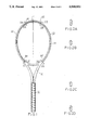
- FIG. 1 is a perspective view of a racket frame embodying the present invention
- FIG. 2A is a sectional view taken along line 2A--2A of FIG. 1;
- FIG. 2B is a sectional view taken along line 2B--2B of FIG. 1;
- FIG. 2C is a sectional view taken along line 2C--2C of FIG. 1;
- FIG. 2D is a sectional view taken along line 2D--2D of FIG. 1;
- FIG. 3 is a left side plan view of the racket frame of FIG. 1;
- FIG. 4 is a right side plan view of the racket frame of FIG. 1;
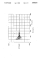
- FIGS. 5 and 6 respectively show the vibrational frequencies of the racket frame of the present invention and a conventional racket frame, as determined by experimentation.
- a racket frame comprises a shaft portion 10, a looped frame portion 20 and a throat 30 formed between the shaft and the looped frame 20.
- the looped frame portion 20 has a first portion 21 and a second portion 22 respectively located on two sides of the longitudinal axis L of the racket frame.
- the longitudinal axis L extends along the shaft 10 and passes through an uppermost point of the frame 20 and the throat 30.
- the cross-section of the looped frame 20 is not uniform.
- the first portion 21 has the smallest cross-section at point A2 and the largest cross-section at point B2.
- the second portion 22 has the largest cross section at point A1 and the smallest cross section at point B1.
- the cross-section of the looped frame portion 20 increases gradually from point B1 to A1, decreases gradually from point A1 to A2, increases gradually from point A2 to point B2, decreases from point B2 to the throat section 30, and increases from point B1 to the throat section 30.
- the cross section of the looped frame portion 20 varies with the changing thickness of the looped frame portion 20 as measured in a direction perpendicular to the plane of the looped frame 20.
- the smallest thickness is 22 mm or 25 mm and the largest thickness is 28 mm.
- FIGS. 5 and 6 shows vibration frequencies as determined by tests performed on a racket constructed according to the present invention and on a conventional racket.
- the greatest peak is 4.2 G and the vibration diminishing period is 63.83 MS.
- the greatest peak is 6.2 G and the vibration diminishing period is 89.10 MS. The results show that the racket incorporating the present invention vibrates less than the conventional racket does.
Landscapes
- Health & Medical Sciences (AREA)
- General Health & Medical Sciences (AREA)
- Physical Education & Sports Medicine (AREA)
- Vibration Dampers (AREA)
- Pinball Game Machines (AREA)
- Laminated Bodies (AREA)
- Vibration Prevention Devices (AREA)
Abstract
The cross section of the looped frame portion 20 of a racket varies with the changing thickness thereof as measured in a direction perpendicular to the plane of the looped frame portion. The looped frame portion has a first and a second portion 21, 22 divided by the longitudinal axis of the racket. The first portion 21 has the smallest cross-section at first point A2 adjacent to an uppermost point of the frame opposite to the throat of the racket and the largest cross-section at second point B2 adjacent to the throat. The second portion 22 has the largest cross-section at a point A1 which is symmetrically positioned on the racket frame with the point A2 of the smallest cross-section of the first portion 21 and the smallest cross-section at another point B1 which is symmetrically positioned on the racket frame with the point B2 of the largest cross-section of the first portion.
Description
This invention relates to a racket frame, and particularly to the construction of the looped portion of a racket frame.
In playing tennis, it is a common phenomenon that shocks are initiated at the string web which strikes a ball and then transmitted, through the looped frame, the shaft and the grip of the racket, to the hand of the player. The player may thus easily become fatigued and even injured. In order to alleviate the problem of shock, shock absorbing devices are provided in the art. Most racket shock absorbing devices are accessory elements which must be added to the looped portion or to the string web of a racket. In the 15 rackets incorporating these shock absorbing devices, the strings have to be passed through these shock absorbing elements thereby causing inconveniences in fabrication.
An object of the invention is to provide a racket frame with an improved construction which itself can reduce shock to the user's arm without the need to provide any additional elements.
According to the present invention, the looped frame portion of a racket frame includes a first and second portion divided by a longitudinal axis which extends along the shaft of the racket and passes through the throat of the racket and an uppermost point opposite the throat. The looped frame portion has a gradually varying cross-section in full length. The first portion has a first point of smallest cross-section adjacent to the uppermost point and a second point of largest cross-section adjacent to the throat. The second portion has a third point of largest cross-section adjacent to the uppermost point and a fourth point of smallest cross-section adjacent to the throat. The first and third points are symmetrically positioned on the racket frame with respect to the longitudinal axis. The second and fourth points are symmetrically positioned on the racket frame with respect to the longitudinal axis.
In an aspect of the invention, the cross-section of the looped frame portion varies by changes in the thickness of said looped frame portion as measured in a direction perpendicular to the plane of said looped frame portion.
The exemplary preferred embodiment will be described in detail with reference to the accompanying drawings, in which:
FIG. 1 is a perspective view of a racket frame embodying the present invention;
FIG. 2A is a sectional view taken along line 2A--2A of FIG. 1;
FIG. 2B is a sectional view taken along line 2B--2B of FIG. 1;
FIG. 2C is a sectional view taken along line 2C--2C of FIG. 1;
FIG. 2D is a sectional view taken along line 2D--2D of FIG. 1;
FIG. 3 is a left side plan view of the racket frame of FIG. 1;
FIG. 4 is a right side plan view of the racket frame of FIG. 1; and
FIGS. 5 and 6 respectively show the vibrational frequencies of the racket frame of the present invention and a conventional racket frame, as determined by experimentation.
Referring to FIGS. 1 to 4, a racket frame comprises a shaft portion 10, a looped frame portion 20 and a throat 30 formed between the shaft and the looped frame 20. The looped frame portion 20 has a first portion 21 and a second portion 22 respectively located on two sides of the longitudinal axis L of the racket frame. The longitudinal axis L extends along the shaft 10 and passes through an uppermost point of the frame 20 and the throat 30.
The cross-section of the looped frame 20 is not uniform. The first portion 21 has the smallest cross-section at point A2 and the largest cross-section at point B2. The second portion 22 has the largest cross section at point A1 and the smallest cross section at point B1. The cross-section of the looped frame portion 20 increases gradually from point B1 to A1, decreases gradually from point A1 to A2, increases gradually from point A2 to point B2, decreases from point B2 to the throat section 30, and increases from point B1 to the throat section 30.
In an example, the cross section of the looped frame portion 20 varies with the changing thickness of the looped frame portion 20 as measured in a direction perpendicular to the plane of the looped frame 20. Preferably, the smallest thickness is 22 mm or 25 mm and the largest thickness is 28 mm.
FIGS. 5 and 6 shows vibration frequencies as determined by tests performed on a racket constructed according to the present invention and on a conventional racket. In FIG. 5, the greatest peak is 4.2 G and the vibration diminishing period is 63.83 MS. In FIG. 6, the greatest peak is 6.2 G and the vibration diminishing period is 89.10 MS. The results show that the racket incorporating the present invention vibrates less than the conventional racket does.
Claims (3)
1. A racket frame having a shaft portion, a looped frame portion, and a throat between said looped frame portion and said shaft portion, said looped frame portion having an uppermost point opposite to said throat, and a first and second portion divided by a longitudinal axis which extends along said shaft portion and passes through said uppermost point and said throat,
said looped frame portion having a gradually varying cross-section,
said first portion having a first point of smallest cross-section adjacent to said uppermost point and a second point of largest cross-section adjacent to said throat,
said second portion having a third point of largest cross-section adjacent to said uppermost point and a fourth point of smallest cross-section adjacent to said throat,
said first and third point being symmetrically positioned on the racket frame with respect to said longitudinal axis,
said second and fourth point being symmetrically positioned on the racket frame with respect to said longitudinal axis.
2. A racket frame as claimed in claim 1, wherein said cross-section of said looped frame portion gradually increases from said fourth point to said third point, decreases from said third point to said first point, increases from said first point to said second point, decreases from said second point to said throat, and increases from said fourth point to said throat.
3. A racket frame as claimed in claim 2, wherein said cross-section varies with the changing thickness of said looped frame portion as measured in a direction perpendicular to the plane of said looped frame portion.
Priority Applications (4)
| Application Number | Priority Date | Filing Date | Title |
|---|---|---|---|
| US07/585,761 US5048830A (en) | 1990-09-20 | 1990-09-20 | Racket frame with shock absorbing characteristics |
| DE4031296A DE4031296C2 (en) | 1990-09-20 | 1990-10-04 | Ball game racket frame with shock absorbing properties |
| FR909012812A FR2668073B1 (en) | 1990-09-20 | 1990-10-17 | RACKET FRAME WITH SHOCK ABSORBING CHARACTERISTICS. |
| GB9100035A GB2251387B (en) | 1990-09-20 | 1991-01-03 | Racket frame with shock absorbing characteristics |
Applications Claiming Priority (1)
| Application Number | Priority Date | Filing Date | Title |
|---|---|---|---|
| US07/585,761 US5048830A (en) | 1990-09-20 | 1990-09-20 | Racket frame with shock absorbing characteristics |
Publications (1)
| Publication Number | Publication Date |
|---|---|
| US5048830A true US5048830A (en) | 1991-09-17 |
Family
ID=24342849
Family Applications (1)
| Application Number | Title | Priority Date | Filing Date |
|---|---|---|---|
| US07/585,761 Expired - Fee Related US5048830A (en) | 1990-09-20 | 1990-09-20 | Racket frame with shock absorbing characteristics |
Country Status (4)
| Country | Link |
|---|---|
| US (1) | US5048830A (en) |
| DE (1) | DE4031296C2 (en) |
| FR (1) | FR2668073B1 (en) |
| GB (1) | GB2251387B (en) |
Cited By (8)
| Publication number | Priority date | Publication date | Assignee | Title |
|---|---|---|---|---|
| US5226651A (en) * | 1991-02-28 | 1993-07-13 | Skis Rossignol S.A. | Longitudinally asymmetric racket |
| FR2686262A1 (en) * | 1991-12-31 | 1993-07-23 | Lo Kun Nan | Racket frame ensuring good shock absorption |
| FR2691073A1 (en) * | 1992-05-14 | 1993-11-19 | Rossignol Sa | Asymmetric tennis or other racquet |
| US5277422A (en) * | 1991-09-27 | 1994-01-11 | Dunlop Limited | Games racket frame |
| US5312102A (en) * | 1993-02-04 | 1994-05-17 | Lisco, Inc. | Variable inertia head racket |
| US6062994A (en) * | 1998-04-10 | 2000-05-16 | Ef Composite Technologies, L.P. | Reinforced racquet with flat string bed |
| US6852048B1 (en) | 2002-05-17 | 2005-02-08 | Ef Composite Technologies, L.P. | Guiding and vibration dampening string tubes for sports racquets |
| US20050148413A1 (en) * | 2002-05-17 | 2005-07-07 | Ef Composite Technologies, L.P. | String bearing assemblies for sports racquets |
Citations (8)
| Publication number | Priority date | Publication date | Assignee | Title |
|---|---|---|---|---|
| GB482164A (en) * | 1937-02-08 | 1938-03-24 | Accles & Pollock Ltd | Improvements relating to shafts for tennis, squash, badminton and other like racquets |
| US3647211A (en) * | 1970-06-08 | 1972-03-07 | James H Doessel | Plastic tennis racket having predetermined cross sections effecting flexibility |
| US4145047A (en) * | 1976-05-27 | 1979-03-20 | Nippon Gakki Seizo Kabushiki Kaisha | Racket |
| US4664380A (en) * | 1984-09-22 | 1987-05-12 | Siegfried Kuebler | Racket having thickened shaft portion |
| US4690405A (en) * | 1983-10-19 | 1987-09-01 | Frolow Jack L | Tennis racket |
| US4911444A (en) * | 1987-11-17 | 1990-03-27 | Yonex Kabushiki Kaisha | Tennis racket |
| US4919438A (en) * | 1988-01-23 | 1990-04-24 | Yonex Kabushiki Kaisha | Tennis racket |
| US4997186A (en) * | 1989-12-08 | 1991-03-05 | Ferrari Importing Company, Inc. | Racket frame having multi-dimensional cross-sectional construction |
-
1990
- 1990-09-20 US US07/585,761 patent/US5048830A/en not_active Expired - Fee Related
- 1990-10-04 DE DE4031296A patent/DE4031296C2/en not_active Expired - Fee Related
- 1990-10-17 FR FR909012812A patent/FR2668073B1/en not_active Expired - Fee Related
-
1991
- 1991-01-03 GB GB9100035A patent/GB2251387B/en not_active Expired - Fee Related
Patent Citations (8)
| Publication number | Priority date | Publication date | Assignee | Title |
|---|---|---|---|---|
| GB482164A (en) * | 1937-02-08 | 1938-03-24 | Accles & Pollock Ltd | Improvements relating to shafts for tennis, squash, badminton and other like racquets |
| US3647211A (en) * | 1970-06-08 | 1972-03-07 | James H Doessel | Plastic tennis racket having predetermined cross sections effecting flexibility |
| US4145047A (en) * | 1976-05-27 | 1979-03-20 | Nippon Gakki Seizo Kabushiki Kaisha | Racket |
| US4690405A (en) * | 1983-10-19 | 1987-09-01 | Frolow Jack L | Tennis racket |
| US4664380A (en) * | 1984-09-22 | 1987-05-12 | Siegfried Kuebler | Racket having thickened shaft portion |
| US4911444A (en) * | 1987-11-17 | 1990-03-27 | Yonex Kabushiki Kaisha | Tennis racket |
| US4919438A (en) * | 1988-01-23 | 1990-04-24 | Yonex Kabushiki Kaisha | Tennis racket |
| US4997186A (en) * | 1989-12-08 | 1991-03-05 | Ferrari Importing Company, Inc. | Racket frame having multi-dimensional cross-sectional construction |
Cited By (9)
| Publication number | Priority date | Publication date | Assignee | Title |
|---|---|---|---|---|
| US5226651A (en) * | 1991-02-28 | 1993-07-13 | Skis Rossignol S.A. | Longitudinally asymmetric racket |
| US5277422A (en) * | 1991-09-27 | 1994-01-11 | Dunlop Limited | Games racket frame |
| FR2686262A1 (en) * | 1991-12-31 | 1993-07-23 | Lo Kun Nan | Racket frame ensuring good shock absorption |
| FR2691073A1 (en) * | 1992-05-14 | 1993-11-19 | Rossignol Sa | Asymmetric tennis or other racquet |
| US5312102A (en) * | 1993-02-04 | 1994-05-17 | Lisco, Inc. | Variable inertia head racket |
| US6062994A (en) * | 1998-04-10 | 2000-05-16 | Ef Composite Technologies, L.P. | Reinforced racquet with flat string bed |
| US6852048B1 (en) | 2002-05-17 | 2005-02-08 | Ef Composite Technologies, L.P. | Guiding and vibration dampening string tubes for sports racquets |
| US20050148413A1 (en) * | 2002-05-17 | 2005-07-07 | Ef Composite Technologies, L.P. | String bearing assemblies for sports racquets |
| US7097576B2 (en) | 2002-05-17 | 2006-08-29 | Ef Composite Technologies, L.P. | String bearing assemblies for sports racquets |
Also Published As
| Publication number | Publication date |
|---|---|
| GB2251387A (en) | 1992-07-08 |
| DE4031296C2 (en) | 1993-12-23 |
| DE4031296A1 (en) | 1992-04-09 |
| GB9100035D0 (en) | 1991-02-20 |
| FR2668073B1 (en) | 1993-01-29 |
| GB2251387B (en) | 1994-08-31 |
| FR2668073A1 (en) | 1992-04-24 |
Similar Documents
| Publication | Publication Date | Title |
|---|---|---|
| US6033324A (en) | Vibration damping device for stringed racquets | |
| US5772541A (en) | Vibration dampened hand-held implements | |
| US4180265A (en) | Implement for striking a ball | |
| US5944624A (en) | Notched, slotted grommet for sports racquet | |
| US5842933A (en) | Implement grip with built-in shock absorber | |
| US4765620A (en) | Racket vibration dampener combined with grommet strip | |
| US4690405A (en) | Tennis racket | |
| US4322076A (en) | Ball-playing racket | |
| JP2507397Y2 (en) | racket | |
| US6203454B1 (en) | Multi-mode vibration absorbing device for implements | |
| US5048830A (en) | Racket frame with shock absorbing characteristics | |
| US5540434A (en) | Tennis racket | |
| US5110125A (en) | Sport racket | |
| US4997186A (en) | Racket frame having multi-dimensional cross-sectional construction | |
| US6565463B2 (en) | Shock-absorbing racket body | |
| EP0173417A1 (en) | Tennis or like racket with convex throat | |
| US6254500B1 (en) | Racket with meshed titanium reinforcement | |
| US5058902A (en) | Ellipsoidal flared racquet handle with distal butt weight | |
| KR20230045557A (en) | Pad structure | |
| US4964635A (en) | Tennis racket | |
| US5062634A (en) | Squash racket | |
| US5037098A (en) | Tennis racquet with tapered profile frame | |
| WO1991012857A3 (en) | Vibration-damped racquet structure | |
| US4655449A (en) | Racket having a grip member spaced from the handle | |
| US5020800A (en) | Shock damping and absorbing racket |
Legal Events
| Date | Code | Title | Description |
|---|---|---|---|
| FPAY | Fee payment |
Year of fee payment: 4 |
|
| REMI | Maintenance fee reminder mailed | ||
| LAPS | Lapse for failure to pay maintenance fees | ||
| FP | Expired due to failure to pay maintenance fee |
Effective date: 19990917 |
|
| STCH | Information on status: patent discontinuation |
Free format text: PATENT EXPIRED DUE TO NONPAYMENT OF MAINTENANCE FEES UNDER 37 CFR 1.362 |