EP4154232B1 - Detecting an object in an environment - Google Patents
Detecting an object in an environment Download PDFInfo
- Publication number
- EP4154232B1 EP4154232B1 EP21748967.3A EP21748967A EP4154232B1 EP 4154232 B1 EP4154232 B1 EP 4154232B1 EP 21748967 A EP21748967 A EP 21748967A EP 4154232 B1 EP4154232 B1 EP 4154232B1
- Authority
- EP
- European Patent Office
- Prior art keywords
- predetermined condition
- deterrent
- output
- environment
- reflected wave
- Prior art date
- Legal status (The legal status is an assumption and is not a legal conclusion. Google has not performed a legal analysis and makes no representation as to the accuracy of the status listed.)
- Active
Links
Images

Classifications
-
- G—PHYSICS
- G08—SIGNALLING
- G08B—SIGNALLING OR CALLING SYSTEMS; ORDER TELEGRAPHS; ALARM SYSTEMS
- G08B29/00—Checking or monitoring of signalling or alarm systems; Prevention or correction of operating errors, e.g. preventing unauthorised operation
- G08B29/18—Prevention or correction of operating errors
- G08B29/183—Single detectors using dual technologies
-
- G—PHYSICS
- G01—MEASURING; TESTING
- G01S—RADIO DIRECTION-FINDING; RADIO NAVIGATION; DETERMINING DISTANCE OR VELOCITY BY USE OF RADIO WAVES; LOCATING OR PRESENCE-DETECTING BY USE OF THE REFLECTION OR RERADIATION OF RADIO WAVES; ANALOGOUS ARRANGEMENTS USING OTHER WAVES
- G01S13/00—Systems using the reflection or reradiation of radio waves, e.g. radar systems; Analogous systems using reflection or reradiation of waves whose nature or wavelength is irrelevant or unspecified
- G01S13/02—Systems using reflection of radio waves, e.g. primary radar systems; Analogous systems
- G01S13/04—Systems determining presence of a target
-
- G—PHYSICS
- G01—MEASURING; TESTING
- G01S—RADIO DIRECTION-FINDING; RADIO NAVIGATION; DETERMINING DISTANCE OR VELOCITY BY USE OF RADIO WAVES; LOCATING OR PRESENCE-DETECTING BY USE OF THE REFLECTION OR RERADIATION OF RADIO WAVES; ANALOGOUS ARRANGEMENTS USING OTHER WAVES
- G01S13/00—Systems using the reflection or reradiation of radio waves, e.g. radar systems; Analogous systems using reflection or reradiation of waves whose nature or wavelength is irrelevant or unspecified
- G01S13/88—Radar or analogous systems specially adapted for specific applications
- G01S13/886—Radar or analogous systems specially adapted for specific applications for alarm systems
-
- G—PHYSICS
- G08—SIGNALLING
- G08B—SIGNALLING OR CALLING SYSTEMS; ORDER TELEGRAPHS; ALARM SYSTEMS
- G08B13/00—Burglar, theft or intruder alarms
- G08B13/18—Actuation by interference with heat, light, or radiation of shorter wavelength; Actuation by intruding sources of heat, light, or radiation of shorter wavelength
- G08B13/181—Actuation by interference with heat, light, or radiation of shorter wavelength; Actuation by intruding sources of heat, light, or radiation of shorter wavelength using active radiation detection systems
-
- G—PHYSICS
- G08—SIGNALLING
- G08B—SIGNALLING OR CALLING SYSTEMS; ORDER TELEGRAPHS; ALARM SYSTEMS
- G08B3/00—Audible signalling systems; Audible personal calling systems
- G08B3/10—Audible signalling systems; Audible personal calling systems using electric transmission; using electromagnetic transmission
-
- G—PHYSICS
- G08—SIGNALLING
- G08B—SIGNALLING OR CALLING SYSTEMS; ORDER TELEGRAPHS; ALARM SYSTEMS
- G08B13/00—Burglar, theft or intruder alarms
- G08B13/18—Actuation by interference with heat, light, or radiation of shorter wavelength; Actuation by intruding sources of heat, light, or radiation of shorter wavelength
- G08B13/189—Actuation by interference with heat, light, or radiation of shorter wavelength; Actuation by intruding sources of heat, light, or radiation of shorter wavelength using passive radiation detection systems
- G08B13/194—Actuation by interference with heat, light, or radiation of shorter wavelength; Actuation by intruding sources of heat, light, or radiation of shorter wavelength using passive radiation detection systems using image scanning and comparing systems
- G08B13/196—Actuation by interference with heat, light, or radiation of shorter wavelength; Actuation by intruding sources of heat, light, or radiation of shorter wavelength using passive radiation detection systems using image scanning and comparing systems using television cameras
- G08B13/19695—Arrangements wherein non-video detectors start video recording or forwarding but do not generate an alarm themselves
-
- G—PHYSICS
- G08—SIGNALLING
- G08B—SIGNALLING OR CALLING SYSTEMS; ORDER TELEGRAPHS; ALARM SYSTEMS
- G08B15/00—Identifying, scaring or incapacitating burglars, thieves or intruders, e.g. by explosives
Definitions
- Motion sensors are designed to monitor a defined area, which may be outdoors (e.g., entrance to a building, a yard, and the like), and/or indoors (e.g., within a room, in proximity of a door or window, and the like). Motion sensors may be used for security purposes, to detect intruders based on motion in areas in which no motion is expected, for example, an entrance to a home at night.
- Some security systems employ a motion sensor in the form of a passive infrared (PIR) detector to sense the presence of a heat-radiating body (i.e., such a heat-radiating body would typically indicate the presence of an unauthorized person) in its field of view, and then issue a deterrent such as an audible alarm sound.
- PIR passive infrared
- Some security systems employ a camera in addition to a motion sensor. It is known to trigger the capture of an image by a camera based on a motion sensor detecting motion.
- US2012/188081 discloses a security system to secure an area, the system having a sensor system to determine a location of a moving object within said area, the sensor system including a radar system; a control device connected to said sensor system; an illumination device to provide a light beam said light beam being directable to different locations in said area; and an actuator controlled by said control device to direct said light beam to a desired location, wherein said control device is configured to direct the light beam to a location where the presence of a living body is determined by said sensor system.
- KR20180129240 discloses an intrusion object detection system which detects and determines an intrusion object to eradicate the intrusion object, and a control method thereof.
- the intrusion object detection system comprises: an active laser for outputting a laser over a 360-degree omnidirectional angle, and receiving a reflected laser that the output laser is reflected on the surface of an object; a drone for autonomously flying to a target position, detecting the object using a proximity sensor, and photographing the object using a camera; and a control module for calculating a position of the object based on the reflected laser received through the active laser, and setting the calculated position of the object as a target position so as to control the drone to autonomously fly to the target position, and to enable the drone to determine the photographed object
- WO2006/093527 relates to autonomous defense of a facility having an adjacent restricted access area.
- detection devices and warning devices as well as deterrent devices.
- the detection devices are radar units and cameras that detect an intruder within the restricted access area. Prior to the intruder entering the restricted access area, the intruder is tracked. When the intruder approaches the facility at a predetermined distance, a warning is provided. If the intruder approaches closer to the facility, then a deterrent is provided. The deterrent can be loud uncomfortable sounds or non-lethal munitions. If the intruder continues to approach the facility, the lethal responses can be delivered in the form of lethal sound or lethal weapons.
- the inventors have identified that using a PIR detector to trigger the issuance of a deterrent can cause a lot of false triggers, for example a deterrent may be output when the PIR detects a pet that is not a security concern. This causes a nuisance for the user of such systems and is undesirable for battery powered systems where available power is limited due to the power that is unnecessarily consumed when issuing such falsely triggered deterrents.
- an apparatus for detecting an object in an environment comprising: a processor configured to: control an active reflected wave detector to measure wave reflections from the environment to accrue measured wave reflection data; process the measured wave reflection data to detect an object in said environment; in response to detection of said object, determine whether a first predetermined condition in respect of the object is met; and if the first predetermined condition is met, control an output device to output a deterrent wherein the processor is further configured to: process further measured wave reflection data accrued by the active reflected wave detector to determine whether, after a predetermined time period has elapsed after output of the deterrent, a second predetermined condition in respect of the object is met, wherein the second predetermined condition comprises that the deterrent was output based on the object being located in a predetermined area within a field of view of the active reflected wave detector, and the object remains in said predetermined area after a predetermined time period has elapsed after output of said deterrent; and if the second
- the processor may be configured to control the active reflected wave detector to measure wave reflections from the environment in response to a motion sensor detecting motion in said environment.
- the first predetermined condition in respect of the object may comprise that the object is determined to be human.
- the first predetermined condition in respect of the object may comprise that the object is located in a predetermined area within a field of view of the active reflected wave detector.
- the output device may comprise a lighting device comprising at least one light source, and in response to determining that the first predetermined condition is met, the processor may be configured to control the at least one light source to emit light as said deterrent.
- the lighting device may comprises an array of multiple light sources configured to illuminate a plurality of regions.
- the processor is configured to process the measured wave reflection data to determine a location of said object in the environment and selectively control one or more of the multiple light sources to emit a beam of light to selectively illuminate said location by selecting a subset of the regions.
- the multiple light sources may be light emitting diodes.
- the output device may comprise a speaker, and in response to determining that the first predetermined condition is met, the processor may be configured to control the speaker to emit audio as said deterrent.
- the audio of said deterrent may be an alarm sound.
- the audio of said deterrent may be an audible speech message.
- the second predetermined condition may be based at least on a direction of travel of said object in the environment determined after a predetermined time period has elapsed after output of said deterrent.
- the processor may be configured to control a camera to capture an image of said environment.
- the processor may be configured to: process further measured wave reflection data accrued by the active reflected wave detector to determine whether a third predetermined condition in respect of the object is met, the third predetermined condition indicative of the object leaving a location in said environment, and if the third predetermined condition is met, the processor is configured to perform at least one of control a speaker to output an audible speech message, the output device comprising said speaker; and control the output device to cease output of the deterrent.
- the output device may comprise a lighting device comprising at least one light source and the processor may be configured to control the at least one light source to emit light as the second deterrent.
- the output device may comprise a speaker, and the processor may be configured to control the speaker to emit audio as the second deterrent.
- the active reflected wave detector may be a radar sensor.
- the processor may be configured to control a camera to capture an image of said environment.
- the apparatus may comprise a housing holding the processor.
- the housing may additionally hold one or any combination of the motion sensor, the active reflected wave detector, and the camera.
- a computer-readable storage medium comprising instructions which, when executed by a processor cause the processor to perform the method steps of claim 12.
- the instructions may be provided on one or more carriers.
- a non-transient memory e.g. a EEPROM (e.g. a flash memory) a disk, CD- or DVD-ROM, programmed memory such as read-only memory (e.g. for Firmware), one or more transient memories (e.g. RAM), and/or a data carrier(s) such as an optical or electrical signal carrier.
- the memory/memories may be integrated into a corresponding processing chip and/or separate to the chip.
- Code (and/or data) to implement embodiments of the present disclosure may comprise source, object or executable code in a conventional programming language (interpreted or compiled) such as C, or assembly code, code for setting up or controlling an ASIC (Application Specific Integrated Circuit) or FPGA (Field Programmable Gate Array), or code for a hardware description language, or any other code for executing by any one or more other processing device, e.g. such as those exemplified herein.
- a conventional programming language interpreted or compiled
- ASIC Application Specific Integrated Circuit
- FPGA Field Programmable Gate Array
- a system for detecting an object in an environment comprising: a first device comprising an active reflected wave detector to measure wave reflections from the environment to accrue measured wave reflection data; an output device; and at least one processor, wherein the at least one processor is configured to perform the method defined in claim 12.
- the first device may comprise the output device.
- the output device may be remote from the first device.
- the first device may comprise a processor of said at least one processor to process the measured wave reflection data to detect an object in said environment.
- This processor may be configured perform at least one of said determination as to whether the first predetermined condition in respect of the object is met; or said control of the output device to output the deterrent based on at least that the first predetermined condition is met.
- the first device may comprise said at least one processor.
- each processor of the at least one processor may be comprised of a plurality of processing units/devices.
- data store or memory is intended to encompass any computer readable storage medium and/or device (or collection of data storage mediums and/or devices).
- data stores include, but are not limited to, optical disks (e.g., CD-ROM, DVD-ROM, etc.), magnetic disks (e.g., hard disks, floppy disks, etc.), memory circuits (e.g., EEPROM, solid state drives, random-access memory (RAM), etc.), and/or the like.
- the functions or algorithms described herein are implemented in hardware, software or a combination of software and hardware in one or more embodiments.
- the software comprises computer executable instructions stored on computer readable carrier media such as memory or other type of storage devices. Further, described functions may correspond to modules, which may be software, hardware, firmware, or any combination thereof. Multiple functions are performed in one or more modules as desired, and the embodiments described are merely examples.
- the software is executed on a digital signal processor, ASIC, microprocessor, microcontroller or other type of processing device or combination thereof.
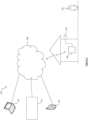
- Figure 1 illustrates a system 100 comprising an environment in which a device 102 has been positioned.
- the environment may for example be an outdoor space such as an area outside of a residential property (e.g. a garden) or commercial property, or a public space (e.g. train station).
- the environment may be an indoor space such as a room of a home, a public building or other indoor space.
- the device 102 is configured to monitor the environment in which a target object (e.g. a person 104) may be present.
- a target object e.g. a person 104
- the device 102 may be coupled to a remote device by way of a wired and/or wireless connection.
- the device 102 may be coupled, preferably wirelessly, to a hub device 106 (otherwise referred to herein as a control hub), which may be in the form of a control panel.
- the control hub 106 may transmit data to a remote monitoring station 110 over a network 108.
- An operator at the remote monitoring station 110 responds as needed to incoming notifications triggered by the device 102 and may also respond to incoming notifications triggered by other similar devices which monitor other environments.
- the device 102 may transmit data to the remote monitoring station 110 without interfacing with the control hub 106.
- the data from the device 102 may be sent (from the device 102 or control hub 106) directly to the remote monitoring station 110 or via a remote server 112.
- the remote monitoring station 110 may be for example a laptop, notebook, desktop, tablet, smartphone or the like.
- control hub 106 may transmit data to a remote personal computing device 114 over a network 108.
- a user of the remote personal computing device 114 is associated with the environment monitored by the device 102, for example the user may be the home owner of the environment being monitored, or an employee of the business whose premises are being monitored by the device 102.
- the device 102 may transmit data to the remote personal computing device 114 without interfacing with the control hub 106.
- the data from the device 102 may be sent (from the device 102 or control hub 106) directly to the remote personal computing device 114 or via the server 112.
- the remote personal computing device 114 may be for example a laptop, notebook, desktop, tablet, smartphone or the like.
- the network 108 may be any suitable network which has the ability to provide a communication channel between the device 102 and/or the control hub 106 to the remote devices 110,112,114.
- FIG. 2 illustrates a simplified view of the device 102.
- the device 102 comprises a central processing unit (“CPU") 202, to which is connected a memory 210.
- the functionality of the CPU 202 described herein may be implemented in code (software) stored on a memory (e.g. memory 210) comprising one or more storage media, and arranged for execution on a processor comprising one or more processing units. That is, the device 102 may comprise one or more processing units for performing the processing steps described herein.
- the storage media may be integrated into and/or separate from the CPU 202.
- the code is configured so as when fetched from the memory and executed on the processor to perform operations in line with embodiments discussed herein.
- the processor that executes the processing steps described herein may be comprised of distributed processing devices, which may for example comprise any one or more of the processing devices or units referred to herein.
- the distributed processing devices may be distributed across two or more devices shown in the system 100.
- FIG. 2 shows the CPU 202 being connected to a motion sensor 204, an active reflected wave detector 206, and a camera 208. While in the illustrated embodiment the motion sensor 204, active reflected wave detector 206, and the camera 208 are separate from the CPU 202, in other embodiments, at least part of processing aspects of the motion sensor 204 and/or active reflected wave detector 206 and/or camera 208 may be provided by a processor that also provides the CPU 202, and resources of the processor may be shared to provide the functions of the CPU 202 and the processing aspects motion sensor 204 and/or active reflected wave detector 206 and/or camera 208. Similarly, functions of the CPU 202, such as those described herein, may be performed in the motion sensor 204 and/or the active reflected wave detector 206 and/or the camera 208.
- the motion sensor 204 may not be present.
- the active reflected wave detector 206 may consume more power in an activated state (i.e. when turned on and operational) than the motion sensor 204 does when in an activated state.
- the camera 208 may not be present.
- a housing 200 of the device 102 may house the motion sensor 204, the active reflected wave detector 206 and the camera 208.
- the motion sensor 204 may be external to the device 102 and be coupled to the CPU 202 by way of a wired or wireless connection.
- the active reflected wave detector 206 may be external to the device 102 and be coupled to the CPU 202 by way of a wired or wireless connection.
- the camera 208 may be external to the device 102 and be coupled to the CPU 202 by way of a wired or wireless connection.
- the outputs of the motion sensor 204 and/or active reflected wave detector 206 and/or camera 208 may be wirelessly received from/via an intermediary device that relays, manipulates and/or in part produces their outputs, for example the control hub 106.
- the CPU 202 is configured to detect motion in the environment based on an output of the motion sensor 204.
- the motion sensor 204 may be a passive infrared (PIR) sensor.
- the motion sensor is preferably a PIR sensor, however it could be an active reflected wave sensor, for example radar, that detects motion based on the Doppler effect.
- the motion sensor 204 may be a radar based motion sensor which detects motion based on the Doppler component of a radar signal.
- the active reflected wave detector 206 may operate in accordance with one of various reflected wave technologies.
- the CPU 202 uses the output of the active reflected wave detector 206 to determine the presence of a target object (e.g. human).
- a target object e.g. human
- the active reflected wave detector 206 is a radar sensor.
- the radar sensor 206 may use millimeter wave (mmWave) sensing technology.
- the radar is, in some embodiments, a continuous-wave radar, such as frequency modulated continuous wave (FMCW) technology.
- FMCW frequency modulated continuous wave
- Such a chip with such technology may be, for example, Texas Instruments Inc. part number IWR6843.
- the radar may operate in microwave frequencies, e.g. in some embodiments a carrier wave in the range of 1-100GHz (76-81Ghz or 57-64GHz in some embodiments), and/or radio waves in the 300MHz to 300GHz range, and/or millimeter waves in the 30GHz to 300GHz range.
- the radar has a bandwidth of at least 1 GHz.
- the active reflected wave detector 206 may comprise antennas for both emitting waves and for receiving reflections of the emitted waves, and in some embodiment different antennas may be used for the emitting compared with the receiving.
- the active reflected wave detector 206 is an "active" detector in the sense of it relying on delivery of waves from an integrated source in order to receive reflections of the waves.
- the active reflected wave detector 206 need not be limited to being a radar sensor.
- the active reflected wave detector 206 is a lidar sensor, or a sonar sensor.
- the active reflected wave detector 206 being a radar sensor is advantageous over other reflected wave technologies in that radar signals may transmit through some materials, e.g. wood or plastic, but not others - notably water which is important because humans are mostly water. This means that the radar can potentially "see” a person in the environment even if they are behind an object of a radar-transmissive material. This is generally not the case for sonar.
- Each of the motion sensor 204 and the active reflected wave detector 206 has a field of view.
- the motion sensor 204 and the active reflected wave detector 206 may be arranged such that their fields of view overlap.
- the fields of view of the motion sensor 204 and the active reflected wave detector 206 may partially or fully overlap. Thus there is at least a partial overlap between the fields of view of the motion sensor 204 and the active reflected wave detector 206.
- the overlapping, or partial overlapping, of the fields of view is, in some embodiments, in the 3D sense. However in other embodiments the overlapping, or partial overlapping, of the fields of view may be in a 2D, plan view, sense. For example there may be an overlapping field of view in the X and Y axes, but with a non-overlap in the Z axis.
- the CPU 202 is configured to control the camera 208 to capture an image (represented by image data) of the environment.
- the camera 208 is preferably a visible light camera in that it senses visible light.
- the camera 208 senses infrared light.
- a camera which senses infrared light is a night vision camera which operates in the near infrared (e.g. wavelengths in the range 0.7 - 1.4 ⁇ m) which requires infrared illumination e.g. using infrared LED(s) which is not visible to an intruder.
- a camera which senses infrared light is a thermal imaging camera which is passive in that it does not require an illuminator, but rather, senses light in a wavelength range (e.g. a range comprising 7 to 15 ⁇ m, or 7 to 11 ⁇ m) that includes wavelengths corresponding to blackbody radiation from a living person (around 9.5 ⁇ m).
- the camera 208 may be capable of detecting both visible light and, for night vision, near infrared light.
- the device 102 may comprise a communications interface 214 for communication of data to and from the device 102.
- the device 102 may communicate with a remote device 106, 110, 112, 114 via the communications interface 214.
- the device 102 may communicate, via the communications interface 214, with one or more of the motion sensor 204, the active reflected wave detector 206, and the camera 208 in embodiments in which such components are not housed in the housing 200 of the device 102.
- the device 102 comprises an output device for outputting deterrents to an intruder in the environment.
- the device may comprise a visual output device in the form of a lighting device 216.
- the lighting device 216 comprises one or more light sources for emitting visible light into the environment.
- the lighting device 216 comprises multiple light sources.
- the multiple light sources are configured to illuminate a plurality of regions of the environment.
- the CPU 202 may selectively control one or more of the multiple light sources to emit a beam of light to a subset (e.g. one region or a cluster of regions) of the plurality of regions to illuminate an intruder wherever they are located.
- the one or more light sources are preferably LEDs due to their low power consumption which is advantageous for battery powered devices, it will appreciated that other types of light source may be used.
- Figure 2 illustrates the lighting device 216 being housed within the housing 200 this is merely an example.
- the lighting device 216 may be coupled to the housing 200 by way of a wired and/or wireless connection.
- the lighting device 216 may be coupled to the control hub 106 by way of a wired and/or wireless connection.
- the device 102 may comprise an audible output device in the form of a speaker 218 for emitting audio.
- audio is used herein to refer to sound having a frequency that is within the human auditory frequency range, commonly stated as 20Hz - 20kHz. Whilst Figure 2 illustrates the speaker 218 being housed within the housing 200 this is merely an example.
- the speaker 218 may be coupled to the housing 200 by way of a wired and/or wireless connection. Alternatively or additionally, the speaker 218 may be coupled to the control hub 106 by way of a wired and/or wireless connection.
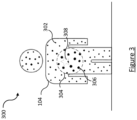
- Figure 3 illustrates a free-standing human body 104 with indications of reflective wave reflections therefrom in accordance with some embodiments.
- the reflected wave measurement may include a set of one or more measurement points that make up a "point cloud", the measurement points representing reflections from respective reflection points from the environment.
- the active reflected wave detector 206 provides an output to the CPU 202 for each captured frame as a point cloud for that frame.
- Each point 302 in the point cloud may be defined by a 3-dimensional spatial position from which a reflection was received, and defining a peak reflection value, and a doppler value from that spatial position.
- a measurement received from a reflective object may be defined by a single point, or a cluster of points from different positions on the object, depending on its size.
- the point cloud represents only reflections from moving points of reflection, for example based on reflections from a moving target. That is, the measurement points that make up the point cloud represent reflections from respective moving reflection points in the environment. This may be achieved for example by the active reflected wave detector 206 using moving target indication (MTI). Thus, in these embodiments there must be a moving object in order for there to be reflected wave measurements from the active reflected wave detector (i.e. measured wave reflection data), other than noise Alternatively, the CPU 202 receives a point cloud from the active reflected wave detector 206 for each frame, where the point cloud has not had pre-filtering out of reflections from moving points.
- MTI moving target indication
- the CPU 202 filters the received point cloud to remove points having Doppler frequencies below a threshold to thereby obtain a point cloud representing reflections only from moving reflection points.
- the CPU 202 accrues measured wave reflection data which corresponds to point clouds for each frame whereby each point cloud represents reflections only from moving reflection points in the environment.
- no moving target indication (or any filtering) is used.
- the CPU 202 accrues measured wave reflection data which corresponds to point clouds for each frame whereby each point cloud can represent reflections from both static and moving reflection points in the environment.
- Figure 3 illustrates a map of reflections.
- the size of the point represents the intensity (magnitude) of energy level of the radar reflections (see larger point 306).
- Different parts or portions of the body reflect the emitted signal (e.g. radar) differently.
- reflections from areas of the torso 304 are stronger than reflections from the limbs.
- Each point represents coordinates within a bounding shape for each portion of the body.
- Each portion can be separately considered and have separate boundaries, e.g. the torso and the head may be designated as different portions.
- the point cloud can be used as the basis for a calculation of a reference parameter or set of parameters which can be stored instead of or in conjunction with the point cloud data for a reference object (human) for comparison with a parameter or set of parameters derived or calculated from a point cloud for radar detections from an object (human).
- a location of a particular part/point on the object or a portion of the object may be determined by the CPU 202 from the cluster of measurement point positions having regard to the intensity or magnitude of the reflections (e.g. a centre location comprising an average of the locations of the reflections weighted by their intensity or magnitude).
- the reference body has a point cloud from which its centre has been calculated and represented by the location 308, represented by the star shape.
- the torso 304 of the body is separately identified from the body and the centre of that portion of the body is indicated.
- the body can be treated as a whole or a centre can be determined for each of more than one body part e.g. the torso and the head, for separate comparisons with centres of corresponding portions of a scanned body.
- the object's centre or portion's centre is in some embodiments a weighted centre of the measurement points.
- the locations may be weighted according to an Radar Cross Section (RCS) estimate of each measurement point, where for each measurement point the RCS estimate may be calculated as a constant (which may be determined empirically for the reflected wave detector 206) multiplied by the signal to noise ratio for the measurement divided by R 4 , where R is the distance from the reflected wave detector 206 antenna configuration to the position corresponding to the measurement point.
- RCS Radar Cross Section
- the RCS may be calculated as a constant multiplied by the signal for the measurement divided by R 4 . This may be the case, for example, if the noise is constant or may be treated as though it were constant.
- the received radar reflections in the exemplary embodiments described herein may be considered as an intensity value, such as an absolute value of the amplitude of a received radar signal.
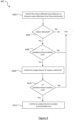
- Figure 4 illustrates an example process 400 which may be performed by the CPU 202 for detecting an object in an environment.
- the CPU 202 controls the active reflected wave detector 206 to measure wave reflections from the environment so that the CPU 202 accrues measured wave reflection data.
- step S402 may be performed in response to a motion sensor detecting motion in the environment. That is, in response to determining that the motion sensor 204 has detected motion in the environment based on receiving an output signal indicative of detected motion from the motion sensor 204, the CPU 202 may perform step S402.
- step S402 the active reflected wave detector 206 may be in a deactivated state. In the deactivated state the active reflected wave detector 206 may be turned off. Alternatively, in the deactivated state the active reflected wave detector 206 may be turned on but in a low power consumption operating mode whereby the active reflected wave detector 206 is not operable to perform reflected wave measurements.
- step S402 comprises the CPU 202 activating the active reflected wave detector 206 so that it is in an activated state and operable to measure wave reflections from a monitored area of the environment 100. The monitored area may correspond to the field of view of the active reflected wave detector 206.
- the CPU 202 processes data output by the active reflected wave detector 206 to determine whether a deterrent should be output.
- step S404 the CPU 202 processes the measured wave reflection data to determine whether an object is present in the environment.
- Various techniques may be used to perform step S404.
- step S404 may be performed using a tracking module in the CPU 202 and the CPU 202 determines that an object is present in the environment because a cluster of detection measurements (also referred to as measurement points above) can be tracked by the tracking module.
- the tracking module can use any known tracking algorithm.
- the active reflected wave detector 206 may generate a plurality of detection measurements (e.g. up to 100 measurements, or in other embodiments hundreds of measurements) for a given frame. Each measurement can be taken a defined time interval apart such as 0.5, 1, 2 or 5 seconds apart.
- Each detection measurement may include a plurality of parameters in response to a received reflective wave signal above a given threshold.
- the parameters for each measurement may for example include an x and y coordinate (and z coordinate for a 3D active reflected wave detector 206), a peak reflection value, and a Doppler value corresponding to the source of the received radar signal.
- the data can then be processed using a clustering algorithm to group the measurements into one or more measurement clusters corresponding to a respective one or more targets.
- An association block of the tracking module may then associate a given cluster with a given previously measured target.
- a Kalman filter of the tracking module may then be used to estimate the next position of the target based on the corresponding cluster of measurements and a prediction by the Kalman filter of the next position based on the previous position and one or more other parameters associated with the target, e.g. the previous velocity.
- other tracking algorithms known by the person skilled in the art may be used.
- the tracking module may output values of location, velocity and/or RCS for each target, and in some embodiments also outputs acceleration and a measure of a quality of the target measurement, the latter of which is essentially to act as a noise filter.
- the values of position (location) and velocity (and acceleration, if used) may be provided in 2 or 3 dimensions (e.g. cartesian or polar dimensions), depending on the embodiment.
- the Kalman filter tracks a target object between frames and whether the Kalman filter's estimation of the objects' parameters converges to the object's actual parameters may depend on the kinematics of the object. For example, more static objects may have a better convergence.
- the performance of the Kalman filter may be assessed in real time using known methods to determine whether the tracking meets a predefined performance metric, this may be based on a covariance of the Kalman filter's estimation of the object's parameters. For example, satisfactory tracking performance may be defined as requiring at least that the covariance is below a threshold.
- the Kalman filter may or may not produce satisfactory performance within a predefined number of frames (e.g. 3-5 frames). The frames may be taken at a rate of 10 to 20 frames per second, for example. If the RCS is outside that range it may be concluded that the object is inhuman.
- the process 400 ends without a deterrent being output by the device 102.
- step S404 If an object is detected at step S404, the process 400 proceeds to step S406 where the CPU 202 determines whether a first predetermined condition in respect of the object is met.
- the CPU 202 may determine whether the detected object is human or not. Any known method for detecting whether the object is human or not can be used. In particular, determining whether the detected object is human may not use a reference object that described above with reference to Figure 3 . In one example, step S406 may be performed using the tracking module referred to above.
- the RCS of the object may be used at step S406 to determine whether the detected object is human or not.
- an RCS of an object represented by a cluster of measurement points can be estimated by summing the RCS estimates of each of the measurement points in the cluster. This RCS estimate may be used to classify the target as a human target if the RCS is within a particular range potentially relevant to humans for the frequency of the signal emitted by the active reflected wave detector 206, as the RCS of a target is frequency dependent.
- the RCS (which is frequency dependent) of an average human may be taken to be in the order of 0.5m 2 , or more specifically in a range between 0.1 and 0.7 m 2 , with the value in this range for a specific person depending on the person and their orientation with respect to the radar.
- the RCS of human in the 57-64GHz spectrum is similar to the 77 GHz RCS - i.e. 0.1 and 0.7 m 2 . If the RCS is outside that range it may be concluded that the object is inhuman.
- the velocity information associated with the object may be used at step S406 to determine whether the detected object is human or not. For example, it may be concluded that no human is present if there is no detected object having a velocity within a predefined range and/or having certain dynamic qualities that are characteristic of a human.
- the process 400 ends without a deterrent being output by the device 102. This advantageously avoids unnecessary/nuisance triggering of the output device when it can be determined that the object is not an intruder and thus saves power consumption.
- the CPU 202 determines whether the object is located in a predetermined area within the field of view of the active reflected wave detector 206.
- location information may be provided by the tracking module referred to above.
- the predetermined area within the field of view of the active reflected wave detector 206 may correspond to a region defined by a virtual fence within the field of view of the active reflected wave detector 206.
- the installer will switch the device to a calibration or configuration mode for the defining of the virtual fence. Exemplary methods for an installer to define such a virtual fence is described in International patent application WO 2020/161 703 A2, filed 4 February 2020 . However, other methods of defining a virtual fence may alternatively be employed.
- a virtual fence described herein is not necessarily defined by co-ordinates that themselves define an enclosed area.
- an installer may simply define a line extending across the field of view of the active reflected wave detector 206 and then configure the virtual fence to encompass an area that extends beyond this line (further away from the active reflected wave detector 206) and is bound by the field of view and range of the active reflected wave detector 206.
- the encompassed area may correspond to the region detectable by active reflected wave detector 206 that is closer than the line.
- the process 400 ends without a deterrent being output by the device 102. This advantageously avoids triggering of the output device when it can be determined that the presence of the object is not a security concern and thus saves power consumption.
- the CPU 202 determines that the first predetermined condition in respect of the object is met, the CPU 202 determines that an intruder is present in an area of interest, and the process 400 proceeds to step S408.
- the "area of interest" corresponds to a portion of the monitored area of the environment.
- the "area of interest” may correspond to the entire monitored area of the environment.
- the monitored area of the environment may for example correspond to the field of view of the active reflected wave detector 206.
- more than one virtual fence may be defined within the field of view of the active reflected wave detector 206, and thus there may be more than one area of interest in the monitored area of the environment.
- the CPU 202 controls an output device of the device 102 to output a deterrent.
- the output of the deterrent is triggered based on a predetermined condition being met based on an output of the active reflected wave detector 206 which provides more relevant triggering than triggering only based on the output of a motion sensor.
- the CPU 202 may control the lighting device 216 to emit light as a visual deterrent to the intruder.
- the lighting device 216 comprises one more light sources, and at step S408 the CPU 202 may control the lighting device 216 to emit light from all of the one or more light sources wherein the light source(s) were not emitting light prior to step S408. That is, all of the light sources(s) of the lighting device 216 are turned on.
- the light emitted by the lighting device 216 is targeted onto the intruder.
- the lighting device 216 comprises multiple light sources which are configured to illuminate a plurality of regions of the environment.
- the CPU 202 processes the accrued measured wave reflection data to determine a location of the intruder in the environment selectively control one or more of the multiple light sources to emit a beam of light to selectively illuminate the determined location by selecting a subset (e.g. one region or a cluster of regions) of the regions. That is, one or more of the multiple light sources are selected to shine a beam on the person wherever they are identified as being from the output of the active reflected wave detector 206, thus giving them an uneasy feeling that they are being watched, or are exposed or more visible.
- a housing of the lighting device 216 that holds one or more light sources may be moveably mounted with respect to a mounting component or assembly (e.g. a bracket).
- a mounting component or assembly e.g. a bracket
- the housing of the lighting device 216 may pivot and/or swivel with respect to mounting component or assembly.
- the relative disposition of the housing of the lighting device 216 with respect the mounting component or assembly may be controlled by one or more motors to enable the direction of illumination to be controlled, as needed.
- the location of the person may be tracked and the illuminated location may change to track the location of the person.
- this may be achieved by selecting a different subset of the plurality of illumination regions.
- this may be achieved by appropriately actuating the motor(s).
- the light source(s) of the lighting device 216 that are controlled to emit light may be controlled to constantly emit light, or may be controlled to emit flashing light.
- the CPU 202 controls the speaker 218 to emit audio as an audible deterrent to the intruder.
- the audio emitted by the speaker 218 may be a non-speech sound e.g. a warning siren. Additionally or alternatively the audio emitted by the speaker 218 may be an audible speech message e.g. "this is private property, please leave the area immediately!.
- the CPU 202 may additionally transmit an alert message to the control hub 106 for subsequent transmission to one or more of the remote monitoring station 110, the server 112 and the remote personal computing device 114. Additionally or alternatively the CPU 202 may transmit the alert message directly to one or more of the remote monitoring station 110, the server 112 and the remote personal computing device 114.
- the CPU 202 may additionally control the camera 208 to capture an image of said environment.
- the CPU 202 may transmit the image data to the control hub 106 for subsequent transmission to one or more of the remote monitoring station 110, the server 112 and the remote personal computing device 114. Additionally or alternatively the CPU 202 may transmit the image data directly to one or more of the remote monitoring station 110, the server 112 and the remote personal computing device 114.
- the process 400 continues after S408 to determine whether it is necessary to output a second deterrent that is to act as an escalated warning of increasing severity e.g. depending on where the person is located and/or their direction of travel and/or other kinetic information. This is described in more detail below.
- step S410 the CPU 202 processes further measured wave reflection data accrued by the active reflected wave detector 206 to determine whether a second predetermined condition related to the object is met.
- step S410 comprises the CPU 202 activating the active reflected wave detector 206 so that it is in an activated state and operable to measure wave reflections from the monitored area of the environment 100.
- the active reflected wave detector 206 remains in an activated state for at least as long as the intruder is present in the area of interest. This enables the object to be tracked to see its velocity and/or to see if the object at a second time t2 (e.g. used in the assessment at step S410 to determine whether the second predetermined condition is met) is the same object as at first time t1 (e.g. used in the assessment at step S406 to determine whether the first predetermined condition is met).
- a second time t2 e.g. used in the assessment at step S410 to determine whether the second predetermined condition is met
- the active reflected wave detector 206 remains in an activated state throughout the process 400.
- the second predetermined condition is based at least on a location of the object in the environment.
- the deterrent output at step S408 has been based on the object being located in a predetermined area within a field of view of the active reflected wave detector 206, and the second predetermined condition comprises that the object has remained in this predetermined area after the predetermined time period has elapsed. If this second predetermined condition is met, this indicates that the intruder has not moved out of the area of interest despite the device 102 outputting the deterrent at step S408.
- the deterrent output at step S408 may have been based on the object being located in a first predetermined area (e.g. a first region defined by a first virtual fence) within a field of view of the active reflected wave detector 206, and the second predetermined condition may comprise that the object has moved such that they are located in a second predetermined area (e.g. a second region defined by a second virtual fence) within the field of view of the active reflected wave detector 206. If this example second predetermined condition is met, this indicates that the intruder has moved into an area of interest that may be more of a concern despite the device 102 outputting the deterrent at step S408.
- the area of interest may be more of a concern by representing a greater security threat, for example by virtue of being closer to a building or other space to be secured.
- the second predetermined condition may be based at least on a direction of travel of the object in the environment. For example, it could be that the object is moving (or has moved) towards the second predetermined area or towards a designated location.
- a direction of travel of the object in the environment For example, it could be that the object is moving (or has moved) towards the second predetermined area or towards a designated location.
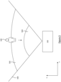
- the deterrent output at step S408 may have been based on the object 104 being located in a first predetermined area 502 (e.g. a first region defined by a first virtual fence) within a field of view 500 of the active reflected wave detector 206, and the second predetermined condition may comprise that the object has moved towards a second predetermined area 504 (e.g. a second region defined by a second virtual fence) within the field of view 500 of the active reflected wave detector 206.
- a first predetermined area 502 e.g. a first region defined by a first virtual fence
- the second predetermined condition may comprise that the object has moved towards a second predetermined area 504 (e.g. a second region defined by a second virtual fence) within the field of view 500 of the active reflected wave detector 206.
- this example second predetermined condition indicates that the intruder has not moved away from the area of interest in a desired direction despite the device 102 outputting the deterrent at step S408 and has instead moved in a direction towards a sensitive area that is more of a security threat (e.g. they have got closer to a building).
- the first predetermined area 502 may be up to but not including the second predetermined area 504. In these examples the first predetermined area 502 may be contiguous with the second predetermined area 504, or the first predetermined area 502 may be non-contiguous with the second predetermined area 504.
- the second predetermined area 504 may be inside (i.e. enclosed by) the first predetermined area 502.
- Figure 5 illustrates the first virtual fence and second virtual fence as both having sections which coincide with a portion of the perimeter of the area of the environment that is monitored by the active reflected wave detector 206, this is merely an example, and any virtual fence described herein need not have a portion that coincides with a portion of the perimeter of the area of the environment that is monitored by the active reflected wave detector 206.
- the second predetermined condition may be based at least on kinetic information associated with the person e.g. their speed of travel.
- the second predetermined condition may be that the speed of the person does not exceed a predetermined threshold.
- this example second predetermined condition may indicate that the intruder is moving out of the area of interest but are doing it too slowly, or they are simply not moving such that they are staying at the same location.
- the speed information may be provided by the tracking module referred to above.
- step S410 determines at step S410 that the second predetermined condition is met, the process 400 proceeds to step S412.
- the CPU 202 controls the output device to output a second deterrent.
- the second deterrent output at step S412 conveys a heightened sense of urgency that the intruder leaves the area.
- the CPU 202 may control the lighting device 216 to emit light as a visual deterrent to the intruder. Alternatively, or additionally at step S412 the CPU 202 may control the speaker 218 to emit audio as an audible deterrent to the intruder. Examples are described below which illustrate how the CPU 202 may control the output device to output a second deterrent which conveys a heightened sense of urgency that the intruder leaves the area.
- the CPU 202 may control one or more of the multiple light sources of the the lighting device 216 to shine a targeted beam on the person as described above with respect to the deterrent output at step S408.
- the CPU 202 may control the light source(s) of the lighting device 216 to flash.
- the CPU 202 may control the speaker 218 to emit audio as an audible deterrent to the intruder in a manner as described above with respect to the deterrent output at step S408.
- the CPU 202 may control one or more of the multiple light sources of the the lighting device 216 to shine a targeted beam on the person as described above with respect to the deterrent output at step S408.
- the CPU 202 may control the light source(s) of the lighting device 216 to flash at an increased frequency.
- the CPU 202 may control the speaker 218 to emit audio as an audible deterrent to the intruder in a manner as described above with respect to the deterrent output at step S408.
- the CPU 202 may control the one or more of the multiple light sources emitting the beam of light to selectively illuminate the location of the intruder to emit a flashing beam at the location of the intruder.
- the CPU 202 may control the speaker 218 to emit audio as an audible deterrent to the intruder in a manner as described above with respect to the deterrent output at step S408.
- the CPU 202 may control the speaker to increase the volume of the emitted non-speech sound, and/or change the alarm pattern of the non-speech sound.
- the CPU 202 may control the speaker 218 to emit an audible speech message.
- the CPU 202 may control the lighting device 216 to emit light as a visual deterrent to the intruder in a manner as described above with respect to the deterrent output at step S408.
- the CPU 202 may control the speaker to increase the volume of the emitted audible speech message and/or to output a different audible speech message.
- the CPU 202 may control the speaker 218 to emit a non-speech sound e.g. a warning siren.
- the CPU 202 may control the lighting device 216 to emit light as a visual deterrent to the intruder in a manner as described above with respect to the deterrent output at step S408.
- step S410 if the CPU 202 determines that that the second predetermined condition is not met the process 400 may end as shown in Figure 4 without any further output by the output device.
- the CPU 202 determines whether a third predetermined condition is met, wherein meeting of the third predetermined condition is indicative of a person leaving a location (e.g. a spot or an area), and if the third predetermined condition is met, the CPU 202 performs at least one of: commanding a ceasing of an outputting of a deterrent (e.g. stops a siren and/or a visual deterrent) and/or controlling the speaker 218 to output an audible speech message for encouraging the person to not return and/or to continue to leave.
- a deterrent e.g. stops a siren and/or a visual deterrent
- the third predetermined condition may be that the object 104 is identified as moving in a direction of leaving the first predetermined area, in which case, the CPU 202 may still control the speaker 218 to emit an audible speech message to encourage the person to continue on their path. For example, the message may be "please continue to leave the area”.
- the third predetermined condition may comprise, or in some embodiments may more specifically be, that the second predetermined condition is not met.
- the CPU 202 may additionally transmit an alert message to the control hub 106 for subsequent transmission to one or more of the remote monitoring station 110, the server 112 and the remote personal computing device 114. Additionally or alternatively the CPU 202 may transmit the alert message directly to one or more of the remote monitoring station 110, the server 112 and the remote personal computing device 114.
- the CPU 202 may additionally control the camera 208 to capture an image of said environment or a part thereof.
- the CPU 202 may transmit the image data to the control hub 106 for subsequent transmission to one or more of the remote monitoring station 110, the server 112 and the remote personal computing device 114.
- the CPU 202 may transmit the image data directly to one or more of the remote monitoring station 110, the server 112 and the remote personal computing device 114.
- a remote device e.g. the control hub 106, the remote monitoring station 110, the server 112, or the remote personal computing device 114.
- a sequence of deterrents may be output after respective predetermined conditions are met the first predetermined condition and the second predetermined condition).
- This sequence of deterrents may comprise deterrents of different types.
- there may be an escalation, or a progressive escalation, to stronger deterrents as the security threat maintains or increases over time.
- sequence of deterrents comprising two types of deterrents for simplicity, it will be appreciated that the sequence of deterrents may comprise more than two types of deterrents, such further deterrents being output if further predetermined conditions are met based on processing further measured wave reflection data accrued by the active reflected wave detector 206.
- the device 102 monitors an outdoor environment of a residential property
- a first predetermined condition it is advantageous to output a first deterrent that is unlikely to disturb (e.g. wake up) the occupants of the property. If the security threat remains or increases over time the likelihood of the occupants of the property being disturbed by way of subsequent deterrents being output may increase. This ensures that a person at home is not unnecessarily woken for a low risk threat but would be alerted for higher risk threats.
- Such escalation advantageously deters an intruder from getting close to or entering a property.
- Escalation of the deterrents is referred to below with reference to an example whereby the processor 202 monitors the presence of an intruder in four different zones of the monitored area of the environment. Each zone being progressively closer to the device 102. It will be appreciated that embodiments of the present disclosure extend to any number of zones in the monitored area of the environment. Such zones may be user configured (e.g. defined by virtual fences). We refer below to example deterrents which may be output when an intruder is detected in each of these zones.
- step S404 the CPU 202 determines that an object is detected but it is located in an outer zone within the field of view of the active reflected wave detector 206 (this determination not being shown in Figure 4 ), the CPU 202 may not output any deterrent.
- the CPU 202 determines that an object has moved from the outer zone towards the device 102 into a warning zone, the CPU 202 controls the lighting device 216 to emit light as a visual deterrent to the intruder in one of the various ways as described above with respect to the deterrent output at step S408.
- the CPU 202 controls the lighting device 216 to emit flashing light at a lower frequency that is within a first frequency range defined by lower and upper frequency values.
- the CPU 202 may optionally additionally control the speaker 218 to emit audio in the form of auditory beeping as an audible deterrent to the intruder.
- the CPU 202 determines that an object has moved from the warning zone towards the device 102 into a deterrent zone, the CPU 202 controls the lighting device 216 to emit light as an escalated visual deterrent to the intruder in one of the various ways as described above with respect to the deterrent output at step S412. In one example, the CPU 202 controls the lighting device 216 to emit flashing light at a higher frequency that is within a second frequency range defined by lower and upper frequency values.
- the CPU 202 may optionally additionally control the speaker 218 to emit more intensive audio e.g. auditory beeping with increased volume or having a different alarm pattern to the previously output auditory beeping, or audio in the form of an audible speech message (e.g. telling the intruder to leave).
- the CPU 202 may process further measured wave reflection data accrued by the active reflected wave detector 206 to determine that an object has moved from the deterrent zone towards the device 102 into an alarm zone (which in this illustrative example is the inner most zone located closest to the device 102). In response to this determination the CPU 202 controls the speaker 218 to emit audio in the form of an alarm siren. The CPU 202 may additionally control the lighting device 216 to emit light as a visual deterrent to the intruder in a manner as described above. The CPU 202 may additionally transmit an alert message to one or more of the remote monitoring station 110, the server 112 and the remote personal computing device 114 (either directly or via the control hub 106).
- the light when the lighting device 216 emits flashing light the light may be emitted with a constant duty cycle (e.g. at a 50% duty cycle). Alternatively the flashing could occur periodically.
- the duty cycle for any given zone referred to above may be constant or it may vary over time (e.g. varying between a lower duty cycle value and an upper duty cycle value).
- the frequency of the light emitted for any given zone referred to above may be constant or it may vary over time (e.g. varying between a lower frequency value and an upper frequency value).
- FIG. 4 has been described above with reference to the CPU 202 of the device 102 performing all of the steps in the process 400, this is just an example. Functions that are described herein as being performed by the CPU 202 may be performed on a distributed processing system that is distributed amongst a plurality of separate apparatuses.
- the processing of measured wave reflection data and the determination as to whether any of the described predetermined conditions are met may be performed by the processor of a remote device that is remote from the device 102.
- the CPU 202 transmits the measured wave reflection data to the remote device for processing.
- the term "module,” as used herein generally represent software, firmware, hardware, or a combination thereof.
- the module represents program code that performs specified tasks when executed on a processor (e.g. CPU or CPUs).
- the program code can be stored in one or more computer readable memory devices.
Landscapes
- Engineering & Computer Science (AREA)
- Physics & Mathematics (AREA)
- Radar, Positioning & Navigation (AREA)
- Remote Sensing (AREA)
- General Physics & Mathematics (AREA)
- Computer Networks & Wireless Communication (AREA)
- Electromagnetism (AREA)
- Computer Security & Cryptography (AREA)
- Radar Systems Or Details Thereof (AREA)
- Measurement Of Velocity Or Position Using Acoustic Or Ultrasonic Waves (AREA)
- Geophysics And Detection Of Objects (AREA)
Applications Claiming Priority (2)
| Application Number | Priority Date | Filing Date | Title |
|---|---|---|---|
| IL276002A IL276002A (he) | 2020-07-12 | 2020-07-12 | זיהוי עצם בסביבה |
| PCT/IL2021/050853 WO2022013864A1 (en) | 2020-07-12 | 2021-07-12 | Detecting an object in an environment |
Publications (2)
| Publication Number | Publication Date |
|---|---|
| EP4154232A1 EP4154232A1 (en) | 2023-03-29 |
| EP4154232B1 true EP4154232B1 (en) | 2025-02-12 |
Family
ID=79555195
Family Applications (1)
| Application Number | Title | Priority Date | Filing Date |
|---|---|---|---|
| EP21748967.3A Active EP4154232B1 (en) | 2020-07-12 | 2021-07-12 | Detecting an object in an environment |
Country Status (5)
| Country | Link |
|---|---|
| US (1) | US12400532B2 (he) |
| EP (1) | EP4154232B1 (he) |
| ES (1) | ES3015469T3 (he) |
| IL (1) | IL276002A (he) |
| WO (1) | WO2022013864A1 (he) |
Families Citing this family (6)
| Publication number | Priority date | Publication date | Assignee | Title |
|---|---|---|---|---|
| WO2020161703A2 (en) | 2019-02-06 | 2020-08-13 | Essence Security International (E.S.I.) Ltd. | Radar location system and method |
| IL276002A (he) | 2020-07-12 | 2022-02-01 | Essence Security International Esi Ltd | זיהוי עצם בסביבה |
| US12527971B2 (en) | 2021-09-13 | 2026-01-20 | Albert Chin-Tang Wey | High emissivity far infrared ceramic module for therapeutic device |
| AU2022204922A1 (en) * | 2022-07-08 | 2024-01-25 | Essence Smartcare Ltd | Monitoring an environment to control an active reflected wave detector |
| US20250124775A1 (en) * | 2023-10-17 | 2025-04-17 | Vivint, Inc. | Generating novelty sounds based on a state of a building |
| US20250218265A1 (en) * | 2023-12-27 | 2025-07-03 | Vivint, Inc. | Generating overlayed sounds to deter perpetration of an event |
Citations (1)
| Publication number | Priority date | Publication date | Assignee | Title |
|---|---|---|---|---|
| WO2006093527A2 (en) * | 2004-07-30 | 2006-09-08 | U.S. Global Nanospace, Inc. | Modular autonomous perimeter security and non-lethal defense system |
Family Cites Families (58)
| Publication number | Priority date | Publication date | Assignee | Title |
|---|---|---|---|---|
| GB2266799A (en) | 1992-04-22 | 1993-11-10 | Albert Hala | Intruder warning alarm system |
| WO2003075035A1 (en) | 2002-03-01 | 2003-09-12 | Hitachi, Ltd. | Detection system |
| US6967612B1 (en) | 2004-10-22 | 2005-11-22 | Gorman John D | System and method for standoff detection of human carried explosives |
| US7463145B2 (en) | 2005-09-22 | 2008-12-09 | Rsi Video Technologies, Inc. | Security monitoring arrangement and method using a common field of view |
| JP2007147532A (ja) | 2005-11-30 | 2007-06-14 | Hitachi Ltd | レーダ装置 |
| US7439902B2 (en) | 2006-12-20 | 2008-10-21 | Glen E. Robertson | Radar controlled automatic target illumination system |
| KR20100016169A (ko) | 2007-04-03 | 2010-02-12 | 휴먼 네트워크 랩스, 아이엔씨. | 로컬 위치와 오버레이 정보를 획득하기 위한 방법 및 장치 |
| US8229458B2 (en) | 2007-04-08 | 2012-07-24 | Enhanced Geographic Llc | Systems and methods to determine the name of a location visited by a user of a wireless device |
| CA2721616A1 (en) | 2008-04-17 | 2009-12-03 | Shilat Optronics Ltd | Intrusion warning system |
| US8547433B2 (en) | 2008-11-09 | 2013-10-01 | Haim Amir | Extended life video camera system and method |
| NL1037342C2 (nl) * | 2009-10-02 | 2011-04-05 | Inventor Invest Holding B V | Beveiligingssysteem en werkwijze voor het beveiligen van een gebied. |
| US20120092502A1 (en) | 2010-10-13 | 2012-04-19 | Mysnapcam, Llc | Systems and methods for monitoring presence and movement |
| GB2488337A (en) | 2011-02-23 | 2012-08-29 | Sharp Kk | A lighting device |
| US9064394B1 (en) | 2011-06-22 | 2015-06-23 | Alarm.Com Incorporated | Virtual sensors |
| US20120327242A1 (en) | 2011-06-27 | 2012-12-27 | Barley Christopher B | Surveillance camera with rapid shutter activation |
| US8742935B2 (en) | 2011-06-30 | 2014-06-03 | General Electric Company | Radar based systems and methods for detecting a fallen person |
| DE102013103002A1 (de) | 2013-03-25 | 2014-09-25 | Insta Elektro Gmbh | Verfahren zum Detektieren einer Änderung innerhalb eines einem Präsenz- oder Überwachungssensor zugeordneten Erfassungsbereiches sowie Überwachungseinrichtung |
| BR112015025888A2 (pt) | 2013-04-09 | 2017-07-25 | Rsi Video Tech Inc | monitoramento de segurança compacto, de baixo custo |
| DE102013208654A1 (de) | 2013-05-10 | 2014-11-13 | Iris-Gmbh Infrared & Intelligent Sensors | Sensorsystem und Verfahren zur Aufnahme eines Handvenenmusters |
| DE102013215207A1 (de) | 2013-08-02 | 2015-02-05 | Robert Bosch Gmbh | Verfahren und Sensorsystem zum Überwachen eines Raumbereiches |
| US9854227B2 (en) | 2015-01-08 | 2017-12-26 | David G Grossman | Depth sensor |
| WO2016143238A1 (ja) | 2015-03-06 | 2016-09-15 | 日本電気株式会社 | カバレッジ制御方法、基地局装置、無線通信システムおよび基地局制御プログラムを格納した非一時的なコンピュータ可読媒体 |
| US20160313442A1 (en) | 2015-04-21 | 2016-10-27 | Htc Corporation | Monitoring system, apparatus and method thereof |
| EP3289430B1 (en) | 2015-04-27 | 2019-10-23 | Snap-Aid Patents Ltd. | Estimating and using relative head pose and camera field-of-view |
| KR102383790B1 (ko) | 2015-05-22 | 2022-04-08 | 삼성전자주식회사 | 주변 환경 인식 방법 및 그 전자 장치 |
| EP3203454A3 (en) | 2016-02-08 | 2017-11-29 | Essence Security International Ltd. | Motion sensor |
| KR101690781B1 (ko) | 2016-03-04 | 2016-12-29 | 주식회사 에센코 | 레이더 감시 시스템의 관심영역 설정 방법 및 그를 위한 장치 |
| US10402938B1 (en) | 2016-03-31 | 2019-09-03 | Gopro, Inc. | Systems and methods for modifying image distortion (curvature) for viewing distance in post capture |
| US10757377B2 (en) | 2016-06-01 | 2020-08-25 | Pixart Imaging Inc. | Surveillance system and operation method thereof |
| CA3027828C (en) | 2016-06-14 | 2019-07-30 | Rodney HERRING | Software-defined radio earth atmosphere imager |
| DE102016115414A1 (de) | 2016-08-19 | 2018-02-22 | Osram Gmbh | Präsenzdetektion bei unbewegten objekten |
| KR102593824B1 (ko) | 2016-08-31 | 2023-10-25 | 삼성전자주식회사 | 카메라를 제어하기 위한 방법 및 그 전자 장치 |
| KR102614012B1 (ko) | 2016-11-08 | 2023-12-14 | 한화비전 주식회사 | 영상처리장치 및 그의 영상제공방법 |
| US10380880B1 (en) | 2016-11-14 | 2019-08-13 | Instant Care, Inc. | Methods of and devices for filtering triggered alarm signals |
| KR20180064951A (ko) | 2016-12-06 | 2018-06-15 | 주식회사 비트센싱 | 레이더와 반사체를 이용한 직선의 가상펜스 시스템 |
| US10912493B2 (en) | 2017-01-06 | 2021-02-09 | Panasonic Intellectual Property Management Co., Ltd. | Sensor and method |
| WO2018156292A1 (en) * | 2017-02-24 | 2018-08-30 | Walmart Apollo, Llc | Systems and methods for delivering products via unmanned mobile lockers |
| US10605905B2 (en) | 2017-04-07 | 2020-03-31 | Osram Sylvania Inc. | Occupancy estimation using nonparametric online change-point detection, and apparatuses, systems, and software for same |
| KR101928995B1 (ko) * | 2017-05-26 | 2018-12-13 | 강종수 | 침입 물체 감지 시스템 및 이의 제어 방법 |
| JP2018200267A (ja) | 2017-05-29 | 2018-12-20 | トヨタ自動車株式会社 | 上方構造物判定装置及び運転支援システム |
| WO2019039028A1 (ja) | 2017-08-24 | 2019-02-28 | 富士フイルム株式会社 | 音響波計測装置及び音響波計測装置の作動方法 |
| US20190098725A1 (en) | 2017-09-28 | 2019-03-28 | Laurence P. Sadwick | Universal Solid State Lighting System |
| US11102492B2 (en) | 2018-02-20 | 2021-08-24 | Arlo Technologies, Inc. | Multi-sensor motion detection |
| US10657784B1 (en) | 2018-05-14 | 2020-05-19 | Amazon Technologies, Inc. | Auxiliary motion detector for video capture |
| CN110728817A (zh) | 2018-07-16 | 2020-01-24 | 霍尼韦尔国际公司 | 一种用于入侵检测的智能微波检测系统和方法 |
| US11501618B1 (en) | 2018-10-19 | 2022-11-15 | Amazon Technologies, Inc. | Security device with user-configurable motion detection settings |
| FR3090160A1 (fr) | 2018-12-18 | 2020-06-19 | Valeo Vision | Procédé d’obtention d’une image d’un objet à classifier et système associé |
| WO2020161703A2 (en) | 2019-02-06 | 2020-08-13 | Essence Security International (E.S.I.) Ltd. | Radar location system and method |
| US11113952B2 (en) | 2019-04-29 | 2021-09-07 | Alarm.Com Incorporated | Machine learning motion sensing with auxiliary sensors |
| US11727722B2 (en) | 2019-10-04 | 2023-08-15 | Leo Portal | Method and system for verifying image identification |
| KR102632388B1 (ko) | 2019-11-25 | 2024-02-02 | 삼성전자주식회사 | 전자장치 및 그 제어방법 |
| JP2021145209A (ja) | 2020-03-11 | 2021-09-24 | キヤノン株式会社 | 電子機器 |
| EP3879507A1 (en) | 2020-03-12 | 2021-09-15 | Hexagon Technology Center GmbH | Visual-acoustic monitoring system for event detection, localization and classification |
| TWI736235B (zh) | 2020-04-27 | 2021-08-11 | 大陸商光寶電子(廣州)有限公司 | 可移動式電子裝置及其操作方法 |
| IL276001A (he) | 2020-07-12 | 2022-02-01 | Essence Security International Esi Ltd | זיהוי עצם בסביבה |
| IL276002A (he) | 2020-07-12 | 2022-02-01 | Essence Security International Esi Ltd | זיהוי עצם בסביבה |
| IL279885A (he) | 2020-12-30 | 2022-07-01 | Essence Security International Esi Ltd | מכשיר לניטור סביבה |
| JP2022114383A (ja) | 2021-01-26 | 2022-08-05 | 株式会社東芝 | 監視装置および監視方法 |
-
2020
- 2020-07-12 IL IL276002A patent/IL276002A/he unknown
-
2021
- 2021-07-12 WO PCT/IL2021/050853 patent/WO2022013864A1/en not_active Ceased
- 2021-07-12 EP EP21748967.3A patent/EP4154232B1/en active Active
- 2021-07-12 US US18/013,494 patent/US12400532B2/en active Active
- 2021-07-12 ES ES21748967T patent/ES3015469T3/es active Active
Patent Citations (1)
| Publication number | Priority date | Publication date | Assignee | Title |
|---|---|---|---|---|
| WO2006093527A2 (en) * | 2004-07-30 | 2006-09-08 | U.S. Global Nanospace, Inc. | Modular autonomous perimeter security and non-lethal defense system |
Also Published As
| Publication number | Publication date |
|---|---|
| US20230245541A1 (en) | 2023-08-03 |
| EP4154232A1 (en) | 2023-03-29 |
| US12400532B2 (en) | 2025-08-26 |
| WO2022013864A1 (en) | 2022-01-20 |
| IL276002A (he) | 2022-02-01 |
| ES3015469T3 (en) | 2025-05-05 |
Similar Documents
| Publication | Publication Date | Title |
|---|---|---|
| EP4154232B1 (en) | Detecting an object in an environment | |
| EP4150598B1 (en) | Detecting an object in an environment | |
| US8120524B2 (en) | Motion detection systems using CW radar in combination with additional sensors | |
| US7411497B2 (en) | System and method for intruder detection | |
| US9311793B2 (en) | Motion and area monitoring system and method | |
| EP4085437B1 (en) | State detection | |
| US20180356509A1 (en) | Radar-based detection system | |
| US20240203222A1 (en) | Detecting an object in an environment | |
| US20240331517A1 (en) | A device for monitoring an environment | |
| CN115703431A (zh) | 用于车辆安全监测的系统和方法 | |
| EP4356361A2 (en) | Occupancy dependent fall detection | |
| CN113377019A (zh) | 监控设备、方法和智能家居系统 | |
| KR20160139637A (ko) | 초광대역 레이더를 이용한 침입자 감시시스템 | |
| US20250110211A1 (en) | State or activity detection | |
| US20240285189A1 (en) | Fall detection | |
| EP3301656A2 (en) | System and method for an alarm system | |
| US20240038040A1 (en) | Security apparatus | |
| KR20240130857A (ko) | 로봇을 이용한 감시 경계 시스템 및 방법 | |
| CN118946912A (zh) | 用于空间中对象入侵估计的安全系统和方法 |
Legal Events
| Date | Code | Title | Description |
|---|---|---|---|
| STAA | Information on the status of an ep patent application or granted ep patent |
Free format text: STATUS: UNKNOWN |
|
| STAA | Information on the status of an ep patent application or granted ep patent |
Free format text: STATUS: THE INTERNATIONAL PUBLICATION HAS BEEN MADE |
|
| PUAI | Public reference made under article 153(3) epc to a published international application that has entered the european phase |
Free format text: ORIGINAL CODE: 0009012 |
|
| STAA | Information on the status of an ep patent application or granted ep patent |
Free format text: STATUS: REQUEST FOR EXAMINATION WAS MADE |
|
| 17P | Request for examination filed |
Effective date: 20221219 |
|
| AK | Designated contracting states |
Kind code of ref document: A1 Designated state(s): AL AT BE BG CH CY CZ DE DK EE ES FI FR GB GR HR HU IE IS IT LI LT LU LV MC MK MT NL NO PL PT RO RS SE SI SK SM TR |
|
| P01 | Opt-out of the competence of the unified patent court (upc) registered |
Effective date: 20230529 |
|
| DAV | Request for validation of the european patent (deleted) | ||
| DAX | Request for extension of the european patent (deleted) | ||
| STAA | Information on the status of an ep patent application or granted ep patent |
Free format text: STATUS: EXAMINATION IS IN PROGRESS |
|
| 17Q | First examination report despatched |
Effective date: 20240131 |
|
| REG | Reference to a national code |
Ref country code: DE Ref legal event code: R079 Free format text: PREVIOUS MAIN CLASS: G08B0013181000 Ipc: G08B0029180000 Ref document number: 602021026034 Country of ref document: DE |
|
| RIC1 | Information provided on ipc code assigned before grant |
Ipc: G08B 15/00 20060101ALN20240926BHEP Ipc: G08B 13/196 20060101ALN20240926BHEP Ipc: G08B 29/18 20060101AFI20240926BHEP |
|
| GRAP | Despatch of communication of intention to grant a patent |
Free format text: ORIGINAL CODE: EPIDOSNIGR1 |
|
| STAA | Information on the status of an ep patent application or granted ep patent |
Free format text: STATUS: GRANT OF PATENT IS INTENDED |
|
| INTG | Intention to grant announced |
Effective date: 20241107 |
|
| GRAS | Grant fee paid |
Free format text: ORIGINAL CODE: EPIDOSNIGR3 |
|
| RAP3 | Party data changed (applicant data changed or rights of an application transferred) |
Owner name: ESSENCE SECURITY INTERNATIONAL (E.S.I.) LTD. |
|
| GRAA | (expected) grant |
Free format text: ORIGINAL CODE: 0009210 |
|
| STAA | Information on the status of an ep patent application or granted ep patent |
Free format text: STATUS: THE PATENT HAS BEEN GRANTED |
|
| AK | Designated contracting states |
Kind code of ref document: B1 Designated state(s): AL AT BE BG CH CY CZ DE DK EE ES FI FR GB GR HR HU IE IS IT LI LT LU LV MC MK MT NL NO PL PT RO RS SE SI SK SM TR |
|
| REG | Reference to a national code |
Ref country code: GB Ref legal event code: FG4D |
|
| REG | Reference to a national code |
Ref country code: CH Ref legal event code: EP |
|
| REG | Reference to a national code |
Ref country code: DE Ref legal event code: R096 Ref document number: 602021026034 Country of ref document: DE |
|
| REG | Reference to a national code |
Ref country code: IE Ref legal event code: FG4D |
|
| REG | Reference to a national code |
Ref country code: SE Ref legal event code: TRGR |
|
| REG | Reference to a national code |
Ref country code: NL Ref legal event code: MP Effective date: 20250212 |
|
| PG25 | Lapsed in a contracting state [announced via postgrant information from national office to epo] |
Ref country code: RS Free format text: LAPSE BECAUSE OF FAILURE TO SUBMIT A TRANSLATION OF THE DESCRIPTION OR TO PAY THE FEE WITHIN THE PRESCRIBED TIME-LIMIT Effective date: 20250512 |
|
| PG25 | Lapsed in a contracting state [announced via postgrant information from national office to epo] |
Ref country code: FI Free format text: LAPSE BECAUSE OF FAILURE TO SUBMIT A TRANSLATION OF THE DESCRIPTION OR TO PAY THE FEE WITHIN THE PRESCRIBED TIME-LIMIT Effective date: 20250212 |
|
| PG25 | Lapsed in a contracting state [announced via postgrant information from national office to epo] |
Ref country code: PL Free format text: LAPSE BECAUSE OF FAILURE TO SUBMIT A TRANSLATION OF THE DESCRIPTION OR TO PAY THE FEE WITHIN THE PRESCRIBED TIME-LIMIT Effective date: 20250212 |
|
| REG | Reference to a national code |
Ref country code: LT Ref legal event code: MG9D |
|
| PG25 | Lapsed in a contracting state [announced via postgrant information from national office to epo] |
Ref country code: IS Free format text: LAPSE BECAUSE OF FAILURE TO SUBMIT A TRANSLATION OF THE DESCRIPTION OR TO PAY THE FEE WITHIN THE PRESCRIBED TIME-LIMIT Effective date: 20250612 Ref country code: NO Free format text: LAPSE BECAUSE OF FAILURE TO SUBMIT A TRANSLATION OF THE DESCRIPTION OR TO PAY THE FEE WITHIN THE PRESCRIBED TIME-LIMIT Effective date: 20250512 |
|
| PG25 | Lapsed in a contracting state [announced via postgrant information from national office to epo] |
Ref country code: NL Free format text: LAPSE BECAUSE OF FAILURE TO SUBMIT A TRANSLATION OF THE DESCRIPTION OR TO PAY THE FEE WITHIN THE PRESCRIBED TIME-LIMIT Effective date: 20250212 |
|
| PG25 | Lapsed in a contracting state [announced via postgrant information from national office to epo] |
Ref country code: HR Free format text: LAPSE BECAUSE OF FAILURE TO SUBMIT A TRANSLATION OF THE DESCRIPTION OR TO PAY THE FEE WITHIN THE PRESCRIBED TIME-LIMIT Effective date: 20250212 |
|
| PG25 | Lapsed in a contracting state [announced via postgrant information from national office to epo] |
Ref country code: PT Free format text: LAPSE BECAUSE OF FAILURE TO SUBMIT A TRANSLATION OF THE DESCRIPTION OR TO PAY THE FEE WITHIN THE PRESCRIBED TIME-LIMIT Effective date: 20250612 Ref country code: LV Free format text: LAPSE BECAUSE OF FAILURE TO SUBMIT A TRANSLATION OF THE DESCRIPTION OR TO PAY THE FEE WITHIN THE PRESCRIBED TIME-LIMIT Effective date: 20250212 |
|
| PG25 | Lapsed in a contracting state [announced via postgrant information from national office to epo] |
Ref country code: BG Free format text: LAPSE BECAUSE OF FAILURE TO SUBMIT A TRANSLATION OF THE DESCRIPTION OR TO PAY THE FEE WITHIN THE PRESCRIBED TIME-LIMIT Effective date: 20250212 Ref country code: GR Free format text: LAPSE BECAUSE OF FAILURE TO SUBMIT A TRANSLATION OF THE DESCRIPTION OR TO PAY THE FEE WITHIN THE PRESCRIBED TIME-LIMIT Effective date: 20250513 |
|
| REG | Reference to a national code |
Ref country code: AT Ref legal event code: MK05 Ref document number: 1766849 Country of ref document: AT Kind code of ref document: T Effective date: 20250212 |
|
| PG25 | Lapsed in a contracting state [announced via postgrant information from national office to epo] |
Ref country code: SM Free format text: LAPSE BECAUSE OF FAILURE TO SUBMIT A TRANSLATION OF THE DESCRIPTION OR TO PAY THE FEE WITHIN THE PRESCRIBED TIME-LIMIT Effective date: 20250212 |
|
| PGFP | Annual fee paid to national office [announced via postgrant information from national office to epo] |
Ref country code: ES Payment date: 20250827 Year of fee payment: 5 |
|
| PG25 | Lapsed in a contracting state [announced via postgrant information from national office to epo] |
Ref country code: DK Free format text: LAPSE BECAUSE OF FAILURE TO SUBMIT A TRANSLATION OF THE DESCRIPTION OR TO PAY THE FEE WITHIN THE PRESCRIBED TIME-LIMIT Effective date: 20250212 |
|
| PGFP | Annual fee paid to national office [announced via postgrant information from national office to epo] |
Ref country code: DE Payment date: 20250722 Year of fee payment: 5 |
|
| PG25 | Lapsed in a contracting state [announced via postgrant information from national office to epo] |
Ref country code: IT Free format text: LAPSE BECAUSE OF FAILURE TO SUBMIT A TRANSLATION OF THE DESCRIPTION OR TO PAY THE FEE WITHIN THE PRESCRIBED TIME-LIMIT Effective date: 20250212 |
|
| PGFP | Annual fee paid to national office [announced via postgrant information from national office to epo] |
Ref country code: GB Payment date: 20250724 Year of fee payment: 5 |
|
| PG25 | Lapsed in a contracting state [announced via postgrant information from national office to epo] |
Ref country code: AT Free format text: LAPSE BECAUSE OF FAILURE TO SUBMIT A TRANSLATION OF THE DESCRIPTION OR TO PAY THE FEE WITHIN THE PRESCRIBED TIME-LIMIT Effective date: 20250212 |
|
| PGFP | Annual fee paid to national office [announced via postgrant information from national office to epo] |
Ref country code: FR Payment date: 20250725 Year of fee payment: 5 |
|
| PGFP | Annual fee paid to national office [announced via postgrant information from national office to epo] |
Ref country code: CH Payment date: 20250801 Year of fee payment: 5 Ref country code: SE Payment date: 20250722 Year of fee payment: 5 |
|
| PG25 | Lapsed in a contracting state [announced via postgrant information from national office to epo] |
Ref country code: EE Free format text: LAPSE BECAUSE OF FAILURE TO SUBMIT A TRANSLATION OF THE DESCRIPTION OR TO PAY THE FEE WITHIN THE PRESCRIBED TIME-LIMIT Effective date: 20250212 Ref country code: CZ Free format text: LAPSE BECAUSE OF FAILURE TO SUBMIT A TRANSLATION OF THE DESCRIPTION OR TO PAY THE FEE WITHIN THE PRESCRIBED TIME-LIMIT Effective date: 20250212 |
|
| PG25 | Lapsed in a contracting state [announced via postgrant information from national office to epo] |
Ref country code: RO Free format text: LAPSE BECAUSE OF FAILURE TO SUBMIT A TRANSLATION OF THE DESCRIPTION OR TO PAY THE FEE WITHIN THE PRESCRIBED TIME-LIMIT Effective date: 20250212 |
|
| PG25 | Lapsed in a contracting state [announced via postgrant information from national office to epo] |
Ref country code: SK Free format text: LAPSE BECAUSE OF FAILURE TO SUBMIT A TRANSLATION OF THE DESCRIPTION OR TO PAY THE FEE WITHIN THE PRESCRIBED TIME-LIMIT Effective date: 20250212 |
|
| REG | Reference to a national code |
Ref country code: DE Ref legal event code: R097 Ref document number: 602021026034 Country of ref document: DE |
|
| PLBE | No opposition filed within time limit |
Free format text: ORIGINAL CODE: 0009261 |
|
| STAA | Information on the status of an ep patent application or granted ep patent |
Free format text: STATUS: NO OPPOSITION FILED WITHIN TIME LIMIT |
|
| 26N | No opposition filed |
Effective date: 20251113 |