EP4153390B1 - Vorrichtung und verfahren zum schneiden einer bahn aus gewebtem blattmaterial - Google Patents
Vorrichtung und verfahren zum schneiden einer bahn aus gewebtem blattmaterial Download PDFInfo
- Publication number
- EP4153390B1 EP4153390B1 EP21807799.8A EP21807799A EP4153390B1 EP 4153390 B1 EP4153390 B1 EP 4153390B1 EP 21807799 A EP21807799 A EP 21807799A EP 4153390 B1 EP4153390 B1 EP 4153390B1
- Authority
- EP
- European Patent Office
- Prior art keywords
- web
- roller assembly
- assembly
- pulley
- knife
- Prior art date
- Legal status (The legal status is an assumption and is not a legal conclusion. Google has not performed a legal analysis and makes no representation as to the accuracy of the status listed.)
- Active
Links
Images


Classifications
-
- B—PERFORMING OPERATIONS; TRANSPORTING
- B26—HAND CUTTING TOOLS; CUTTING; SEVERING
- B26D—CUTTING; DETAILS COMMON TO MACHINES FOR PERFORATING, PUNCHING, CUTTING-OUT, STAMPING-OUT OR SEVERING
- B26D1/00—Cutting through work characterised by the nature or movement of the cutting member or particular materials not otherwise provided for; Apparatus or machines therefor; Cutting members therefor
- B26D1/01—Cutting through work characterised by the nature or movement of the cutting member or particular materials not otherwise provided for; Apparatus or machines therefor; Cutting members therefor involving a cutting member which does not travel with the work
- B26D1/04—Cutting through work characterised by the nature or movement of the cutting member or particular materials not otherwise provided for; Apparatus or machines therefor; Cutting members therefor involving a cutting member which does not travel with the work having a linearly-movable cutting member
- B26D1/045—Cutting through work characterised by the nature or movement of the cutting member or particular materials not otherwise provided for; Apparatus or machines therefor; Cutting members therefor involving a cutting member which does not travel with the work having a linearly-movable cutting member for thin material, e.g. for sheets, strips or the like
-
- B—PERFORMING OPERATIONS; TRANSPORTING
- B26—HAND CUTTING TOOLS; CUTTING; SEVERING
- B26D—CUTTING; DETAILS COMMON TO MACHINES FOR PERFORATING, PUNCHING, CUTTING-OUT, STAMPING-OUT OR SEVERING
- B26D7/00—Details of apparatus for cutting, cutting-out, stamping-out, punching, perforating, or severing by means other than cutting
- B26D7/06—Arrangements for feeding or delivering work of other than sheet, web, or filamentary form
-
- B—PERFORMING OPERATIONS; TRANSPORTING
- B26—HAND CUTTING TOOLS; CUTTING; SEVERING
- B26D—CUTTING; DETAILS COMMON TO MACHINES FOR PERFORATING, PUNCHING, CUTTING-OUT, STAMPING-OUT OR SEVERING
- B26D7/00—Details of apparatus for cutting, cutting-out, stamping-out, punching, perforating, or severing by means other than cutting
- B26D7/08—Means for treating work or cutting member to facilitate cutting
- B26D7/14—Means for treating work or cutting member to facilitate cutting by tensioning the work
-
- B—PERFORMING OPERATIONS; TRANSPORTING
- B65—CONVEYING; PACKING; STORING; HANDLING THIN OR FILAMENTARY MATERIAL
- B65H—HANDLING THIN OR FILAMENTARY MATERIAL, e.g. SHEETS, WEBS, CABLES
- B65H35/00—Delivering articles from cutting or line-perforating machines; Article or web delivery apparatus incorporating cutting or line-perforating devices, e.g. adhesive tape dispensers
- B65H35/04—Delivering articles from cutting or line-perforating machines; Article or web delivery apparatus incorporating cutting or line-perforating devices, e.g. adhesive tape dispensers from or with transverse cutters or perforators
- B65H35/06—Delivering articles from cutting or line-perforating machines; Article or web delivery apparatus incorporating cutting or line-perforating devices, e.g. adhesive tape dispensers from or with transverse cutters or perforators from or with blade, e.g. shear-blade, cutters or perforators
-
- B—PERFORMING OPERATIONS; TRANSPORTING
- B65—CONVEYING; PACKING; STORING; HANDLING THIN OR FILAMENTARY MATERIAL
- B65H—HANDLING THIN OR FILAMENTARY MATERIAL, e.g. SHEETS, WEBS, CABLES
- B65H2301/00—Handling processes for sheets or webs
- B65H2301/50—Auxiliary process performed during handling process
- B65H2301/51—Modifying a characteristic of handled material
- B65H2301/515—Cutting handled material
- B65H2301/5151—Cutting handled material transversally to feeding direction
- B65H2301/51512—Cutting handled material transversally to feeding direction using a cutting member moving linearly in a plane parallel to the surface of the web and along a direction crossing the handled material
-
- B—PERFORMING OPERATIONS; TRANSPORTING
- B65—CONVEYING; PACKING; STORING; HANDLING THIN OR FILAMENTARY MATERIAL
- B65H—HANDLING THIN OR FILAMENTARY MATERIAL, e.g. SHEETS, WEBS, CABLES
- B65H2404/00—Parts for transporting or guiding the handled material
- B65H2404/10—Rollers
- B65H2404/14—Roller pairs
- B65H2404/143—Roller pairs driving roller and idler roller arrangement
-
- B—PERFORMING OPERATIONS; TRANSPORTING
- B65—CONVEYING; PACKING; STORING; HANDLING THIN OR FILAMENTARY MATERIAL
- B65H—HANDLING THIN OR FILAMENTARY MATERIAL, e.g. SHEETS, WEBS, CABLES
- B65H2701/00—Handled material; Storage means
- B65H2701/10—Handled articles or webs
- B65H2701/17—Nature of material
- B65H2701/174—Textile; fibres
Definitions
- This invention relates to apparatus for cutting a web of sheet material, and particularly a moving web in a processing line.
- a typical example of such a web is a woven plastic of such high tendency to stretching. If it is attempted to cut such a web with the knife arrangement of, for example, U.S. Pat. No.3,794,255 , the required elongation will occur between the knife and the winding roll causing excessive knife travel. In addition, some web materials, depending upon their coefficient of friction, will skid against the driving drum before enough tension can be developed to cut the web
- US patent 3611856 discloses web cutter for cutting a web of material into web portions of a predetermined size.
- the '856 invention further discloses a cutter system which is placed perpendicular to the direction of the web.
- Such '856 invention does not disclose about the cross cutting method or technique of web cutting. Since the cross cutting method is advantageous during high speed cutting, so the '856 invention lacks the precise cutting of web with high speed moving wet
- a device for cutting polywoven bags is known from CN 209699974U , which includes a cutting bed and rubber rollers.
- WO2013130045 A1 discloses an inkjet printer with diagonal media cutter with a cutting platform onto which the continuous moving media from an unwinder is conveyed and passes through a set of web guiding rollers, a pre-draw roller assembly and post-draw roller assembly, a cross cutter apparatus having moveable knife assembly, mounted for diagonal cut at an inclined angle between said roller assemblies, wherein said cross cutter apparatus is capable of cutting said media into pieces using said movable knife assembly in between of the rollers on the cutting platform.
- the main objective of the present invention is to provide a cutting apparatus or device or system to facilitate accurate cutting of a continuously moving web made of woven plastic.
- a further objective of the present invention is to provide a cutting device or system which allows rapid cutting of a continuously moving web made of woven plastic with low maintenance cost.
- Another objective of the present invention is to provide a cutting device or system which provides flexibility in handling of different specification webs without much alteration in the device or system.
- the web or fabric cutting apparatus of the present invention comprises a transport table for the workpiece movement and a movable knife, the knife being preferably guided along an orbit.
- the web cutting apparatus disclosed herein enables highest throughput rates of workpieces and whereby the web cutting apparatus is advantageously used for the separation of workpieces from a woven plastic web.
- the knife When the knife is in an orbit, it can be guided at a uniform speed, reducing power consumption for the gear motor or the drive, increasing life and reducing maintenance.
- the knife in the form of a blade, is mounted on a conveyance means, such as a belt.
- the conveyance means rotates in a direction that is nearly transverse to the direction of movement of the unrolling web or fabric.
- the roll carrying a fabric that needs cutting into pieces is unwound from an unwinding unit.
- the fabric may be made of stretched plastic tape, which is optionally coated, or of plastic film, or of composite materials of fabric and plastic films.
- the unwound fabric travels on a transportation means or a conveyance means onto a cutting platform.
- the conveyance means may be operated using driven rollers, for example.
- Adjacent to the worktable is provided a transverse transport device which is in the form of a conveyor belt (not shown), and clamping means for workpieces, such as grippers or magnets.
- the separation of a leading workpiece from the continuously arriving unrolled fabric takes place by means of the apparatus disclosed herein which essentially is a cutting device which comprises at least one movable knife, wherein the knife is guided along an orbit, which in the circumferential direction, substantially transversely to the longitudinal transport direction aligned endless belt to which at least one blade is fixed.
- the endless belt runs around two rollers, at least one of the two rollers is driven by a motor with speed controller, preferable a servomotor.
- the knife severed the incoming workpiece across the width by travelling at controlled speed based on incoming workpiece traverse rate.
- the cut made using the device disclosed herein is of high quality, i.e. a smooth and precise cut is produced.
- the transverse transport device conveys individual workpieces, away from the work area in a transverse transport direction which is oriented orthogonally to the longitudinal transport direction.
- the knife In a subsequent process step, once the knife has already completely cut off the single workpiece from the contiguous workpieces, it moves along its orbit to the top of the endless belt and thus out of contact with the workpieces.
- the individual workpiece is conveyed away from the working area by means of the transverse transport device in the transverse transport direction.
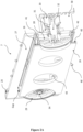
- Figure 1 shows the apparatus of the present invention which is a web or fabric cutting apparatus (1) which facilitates accurate cutting of a continuously moving web (2) made of woven fabric such as plastic.
- the apparatus (1) comprises of a first side plate (4) and a second side plate (5) which are connected to and supported by a base frame structure (3) and cross cutting apparatus (7) with moving knife assembly (38).
- the base frame structure (3) is constructed of a plurality of the rectangular cross-sectional members which are jointed or welded together to form a sturdy base.
- the side plates (4, 5) are constructed in the form of a thick plates and are attached to the base frame structure (3) by any kind of joining means such as welding, bolting or screwing to form a rigid member.
- the apparatus (1) further comprises a cutting platform (8) onto which the continuous moving web (2) from the unwinder (not shown) is conveyed in the direction shown by dotted arrow in Figure 1 by a pull-off driven roller (not shown) and passes through a set of web guiding rollers (6, 6A, and 6B) to maintain proper tension and avoiding shrinkage of the web (2).
- the apparatus (1) also comprises of a pre-draw roller assembly (9) and post-draw roller assembly (11).
- a cross cutter apparatus (7) the cutting of the moving web (2) takes place in between of the rollers (9, 11) on the cutting platform (8), whereby the continuous web (2) is converted into the web cut pieces (15).
- the pre draw roller assembly (9) and post draw roller assembly (11) are individually constructed in such a way that they both have a plurality of rollers mounted on a single shaft.
- the apparatus (1) further comprises of first tension rollers assembly (13) and second tension roller assembly (14) which are used for the holding of the web (2) and also presses the web (2) from above onto the pre-draw roller assembly (9) and post-draw roller assembly (11) all over the traverse web length with the help of pneumatic cylinders such that web (2) lies between the roller assemblies (9, 11, 13, and 14) .
- the first pneumatic cylinder (16) and second pneumatic cylinder (17) works together in the downwards direction and pushes the first tension roller assembly (13) at both ends.
- the first and second pneumatic cylinders (16, 17) are connected to the tension roller assembly (13) via a first lever (20) and second lever (21) respectively.
- the said connection can be obtained by any mechanical method of bolting, screwing or using bush or bearing arrangement such that the downwards movement of the cylinders (16,17) facilitates the movement of the first tension roller assembly (13) to press the web (2) against the pre draw roller (9).
- first tension roller assembly (13) and second tension roller assembly (14) are responsible for maintaining adequate tension in and holding of the web (2) during cutting so that clean and accurate cutting takes place.
- This web tension is created by the difference in speed between the pre-draw roller assembly (9) and post -draw roller assembly (11).
- the post-draw roller assembly (11) speed measured in rpm is slightly higher than the speed of pre-draw roller assembly (9), the rpm of pre draw roller assembly (9) is controlled by the first motor (10) and the rpm of post draw roller assembly (11) is controlled by second motor (12).
- Such difference in the rpm is also required to pull the web (2) in the direction of web movement axis (57).
- a third pneumatic cylinder (18) and fourth pneumatic cylinder (19) work together in the downward direction and push the second tension roller assembly (14) at both ends.
- the third and fourth pneumatic cylinders (18, 19) are connected to the second tension roller assembly (14) at the ends via a third lever (20) and fourth lever (23) respectively.
- the said connection can be obtained by any mechanical method of bolting, screwing or using bush or bearing arrangement such that the downward movement of the cylinders (18,19) facilitates the movement of the second tension roller assembly (14) to press the web (2) against the post draw roller (11).
- pre draw roller assembly (9) and post draw roller assembly (11) are identical in construction with plurality of rollers. These rollers can be chosen from the set of rolling members such that while drawing the web (2) in the direction of web movement axis (57) the rollers provide negligible friction to the surface of web (2) due to which the web (2) does not get damaged.
- the first tension roller assembly (13) and second tension roller assembly (14) also comprises of plurality of rollers mounted on a first and second rod (65, 66) respectively thereby connecting the rod (65, 66) individually with the at least two brackets (67).
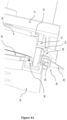
- Cross cutter apparatus (7) is located on the cutting platform (8) at an inclined angle ⁇ as shown in figure 5 perpendicular in direction with respect to the web movement direction (56) and cross cutter apparatus (7) mounted on the first side plate (4) and second side plate (5) via first holding block (24) and second holding block (25).
- the said mounting can be achieved by any mechanical means such as bolting, screwing or welding.
- the cross cutter apparatus further comprises of a rear plate (27) wherein at the ends of the said rear plate (27), a first pulley (28) and at the other end a second pulley (29) are mounted.
- the said first pulley (28) is connected to third pulley (30) via first stationary housing (31) and a first rotating shaft (32) and on the other end second pulley (29) mounted on the rear plate (27) is connected with the adjustment bracket (33) as shown in figure 5 and second rotating shaft (34).
- the second pulley (29) can be moved farther from the first pulley (28). Such movement is required to increase or decrease the tension in the first endless belt (36) which passes over the pulleys (28,29).
- third pulley (30) is driven by fourth pulley (35) shown in figure 3 through endless second belt (37).
- the rotation is transmitting from third motor (47) as shown in Figure 3 which is mounted on first side plate (4) to fourth pulley (35) and from fourth pulley (35) to third pulley (30) which are connected through endless second belt (37) and then from third pulley (30) which are directly coupled to first pulley (28) and finally from first pulley (28) to second pulley (29) which are connected through endless first belt (36).
- the pulleys can be selected from the set of round grooved members having toothed or non-toothed profile, such that profile can be of any shape or size which can drive the belts along with it. Also, these pulleys are efficient enough to transmit the motor power and drive the belts smoothly.
- the belts can be selected from set of flexible members having toothed profile same as of pulleys and can withstand the wear and tear.
- the belts can be of any type such as flat belts, V belts, round belts, spring belts, multi groove belts, timing belts, speciality belts or of any kind known to person skilled in art.
- Movable knife assembly (38) mounted on the first endless belt (36) which makes movable knife assembly (38) rotates in the orbit that is circumferential on the path of the first endless belt (36) which runs over the first pulley (28) and second pulley (29) to cut the web fabric in to workpiece smoothly.
- the said movable knife assembly (38) is further supported and guided by the guide rails in between first pulley (28) and second pulley (29) on top and bottom positions.
- the said guide rails are mounted on the front plate (26) and rear plate (27) in such a manner that opposite guide rails face each other.
- the first Guide rail (39) and the second guide rail (40) are mounted on the front plate (26) at top and bottom position where as the third guide rail (41) and fourth guide rail (42) are mounted on the rear plate (27) exactly opposite to the first guide rail (39) and second guide rail (40) as shown in Figure 2A .
- these guide rails may be made of any shape such as u shape cross section or any other cross section such as v shape, curve shape such that the movable knife assembly moves freely through it.
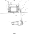
- FIG 3 shows perspective view of the cross cutter apparatus (7) comprises of front protective cover (45) and a swivel cover (46).
- Front protection cover (45) covers the knife (48) moving path to avoid any accident and pulley cover (58) is also provided to cover the rotating part to avoid any accident.
- one swivel cover (46) is provided for the changing of the knife (48) when the knife (48) is worn-out so that there is no need to open the whole cross cutter apparatus (7) for changing the worn out knife which has to be done periodically.
- the cross cutter apparatus (7) is driven by the third motor (47) which is coupled with the fourth pulley (35) and is connected to the third pulley (30) via endless belt (37).
- the front protective cover (45) may be constructed of a sheet metal or plate bend to form a rigid body which can withstand the external impact if occur during the cutting process.
- the swivel cover (46) can also be constructed of a sheet metal or plate bend to form a rigid surface. Also, the swivel cover (46) can be opened and closed whenever the blade (48) of the movable knife assembly (38) requires to be changed when it is worn out. Such change can take place by driving the movable knife assembly (38) to position D (62) and thereby opening the swivel cover (46). The position D (62) can be determined by set of sensors (not shown) which governed the stoppage of the movable knife assembly (38).
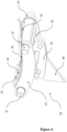
- Figure 4 shows the movable knife assembly (38) which comprises of knife holding bracket (49) on which the knife (48) is located and mounted through the knife holding plate (50) such that knife (48) lies between the holding bracket (49) and holding plate (50).
- the knife (48) can be selected from set of any sharp object which is capable of cutting the web (2) perfectly and smoothly without any hindrance.
- the said movable knife assembly (38) also comprises of first opening (63) and second opening (64) for positioning of first endless belt (36) through which, the movement of the movable knife assembly (38) is driven.
- Figure 4A shows perspective view of movable knife assembly (38) wherein guide pin (52) moves along the profile of the fourth guide rail (42) and second guide rail (40).
- the movable knife assembly (38) is connected to the first endless belt (36) such that the said movable knife assembly (38) is driven by the first endless belt (36) along the path as defined by the first endless belt (36).
- Figures 5 and 5A show the top view of cross cutter apparatus (7) and schematic view of the cutting operation. As shown in the Figures 5 and 5A cross cutter apparatus (7) is mounted at an inclined angle ⁇ perpendicular in direction with respect to the web (2) movement direction axis (57).
- Cutting speed of cross cutter is set in such a way so that time required by the knife (48) to travel from position A (59) to position B (60) is same as the time required taken by the fabric to move from position C (61) to position B (60).
- Inclined mounting of cross cutter apparatus (7) provides the flexibility to the system to set the driving speed of the cutter knife (48) with respect to the continuous moving web (2).
- the present invention also provides a method of cutting a moving web (2).
- the said method uses the apparatus (1) for cutting a moving web (2) disclosed on the foregoing pages.
- the method of the cross-cutting of the moving web (2) according to the present invention comprises of following steps:
- the rotational speed of said post-draw roller assembly (11) is slightly higher than the rotational speed of the pre-draw roller assembly (11) and wherein the rotational speed of said pre draw roller (9) is controlled by a first motor (10) and the rotational speed of said post draw roller (11) is controlled by a second motor (12).
- the cutting speed of said cross cutter (7) is set in such a way that time required by said knife (48) to travel from a position A (59) on first longitudinal edge (68) of fabric (2) to a position B (60) on the second longitudinal edge (69) of said fabric (2) is same as the time required by the fabric (2) to travel the distance between the position on said second longitudinal edge (9) that corresponds to said position A to position B (60).
Landscapes
- Life Sciences & Earth Sciences (AREA)
- Forests & Forestry (AREA)
- Engineering & Computer Science (AREA)
- Mechanical Engineering (AREA)
- Treatment Of Fiber Materials (AREA)
Claims (15)
- Vorrichtung zum Schneiden einer Bahn (2) eines gewebten Schichtmaterials, dadurch gekennzeichnet, dass die Vorrichtung aufweist:- eine erste Seitenplatte (4) und eine zweite Seitenplatte (5), die mit einer Bodenrahmenstruktur (3) verbunden sind und von dieser gestützt werden;- eine Schneideplattform (8), auf welche die sich kontinuierlich bewegende Bahn (2) von einem Abwickler befördert wird und durch einen Satz von Bahnführungsrollen (6, 6A und 6B) hindurch verläuft, um eine geeignete Spannung beizubehalten und dadurch ein Schrumpfen der Bahn (2) zu vermeiden;- eine Vorzugrollenanordnung (9) und eine Nachzugrollenanordnung (11), die beide einzeln so konstruiert sind, dass sie eine Vielzahl von Rollen aufweisen, die auf einer einzelnen Welle montiert sind;- eine Querschneidevorrichtung (7), die eine bewegliche Messeranordnung (38) aufweist, die in einem geneigten Winkel zwischen den Rollenanordnungen (9, 11) montiert ist;- eine erste Spannungsrollenanordnung (13) und eine zweite Spannungsrollenanordnung (14), die jeweils entsprechend der Vorzuganordnung (9) und der Nachzuganordnung (11) montiert sind;- ein Paar pneumatischer Zylinder, nämlich ein erster pneumatischer Zylinder (16) und ein zweiter pneumatischer Zylinder (17), die jeweils mit der ersten Spannungsrollenanordnung (13) unter Verwendung eines ersten Hebels (20) und eines zweiten Hebels (21) verbunden sind, und ein weiteres Paar pneumatischer Zylinder, nämlich ein dritter pneumatischer Zylinder (18) und ein vierter pneumatischer Zylinder (19) entsprechend der zweiten Spannungsrollenanordnung (14), die jeweils mit der zweiten Spannungsrollenanordnung (14) unter Verwendung eines dritten Hebels (22) und eines vierten Hebels (23) verbunden sind,wobei die Querschneidevorrichtung (7) in der Lage ist, die Bahn (2) unter Verwendung der beweglichen Messeranordnung (38) zwischen den Rollen (9, 11) der Schneideplattform (8) zu schneiden, wobei die kontinuierliche Bahn (2) in die Bahnschnittteile (15) geschnitten wird.
- Vorrichtung nach Anspruch 1, wobei die Verbindungen mit dem ersten Hebel (20) und dem zweiten Hebel (21) mit der ersten Spannungsrollenanordnung (13) und jene des dritten Hebels (23) und des vierten Hebels (24) mit der zweiten Spannungsrollenanordnung (14) von einem Typ sein können, der aus einer verriegelten, verschraubten und Buchsen- oder Lageranordnung ausgewählt wird, wobei die Abwärtsbewegung der entsprechenden Zylinder (16, 17 und 18, 19) die Bewegung der ersten Spannungsrollenanordnung (13) zum Drücken der Bahn (2) gegen die Vorzugrolle (9) und jene der zweiten Spannungsrollenanordnung (14) zum Drücken der Bahn (2) gegen die Nachzugrolle (11) erleichtert.
- Vorrichtung nach einem der Ansprüche 1 und 2, wobei bei der Verwendung die Drehzahl der Nachzugrollenanordnung (11) leicht höher als die Drehzahl der Vorzugrollenanordnung (9) ist, wobei die Drehzahl der Vorzugrollenanordnung (9) durch einen ersten Motor (10) gesteuert wird und die Drehzahl der Nachzugrollenanordnung (11) durch einen zweiten Motor (12) gesteuert wird.
- Vorrichtung nach einem der Ansprüche 1 bis 3, wobei die Vorzugrollenanordnung (9) und die Nachzugrollenanordnung (11) hinsichtlich der Konstruktion identisch sind und eine Vielzahl von Rollen aufweisen, und wobei die erste Spannungsrollenanordnung (13) und die zweite Spannungsrollenanordnung (14) eine identische Konstruktion aufweisen, die jeweils aus einer Vielzahl von Rollen hergestellt ist, die jeweils auf einem Satz einer ersten und einer zweiten Stange (65, 66) montiert sind, wobei die ersten Stangen (65) unter Verwendung eines Satzes von Halterungen (67) miteinander verbunden sind.
- Vorrichtung nach einem der Ansprüche 1 bis 4, wobei die Querschneidevorrichtung (7) aufweist:- zwei parallele Platten, eine vordere Platte (26) und eine hintere Platte (27), die in einem vorbestimmten Spalt montiert sind, der durch einen Satz von oberen flachen Abstandshaltern (44) und einen Satz von unteren zylinderförmigen Abstandshaltern (43) beibehalten wird;- ein erstes Riemenrad (28), das an einem Ende der hinteren Platte (27) montiert ist, ist mit einem dritten Riemenrad (30) über ein erstes feststehendes Gehäuse (31) und eine erste Rotationswelle (32) verbunden, und ein zweites Riemenrad (29), das an dem anderen Ende der hinteren Platte (27) montiert ist, ist mit einer Einstellhalterung (33) und einer zweiten Rotationswelle (34) verbunden;- ein erster Endlosriemen (36), welcher über die Riemenscheiben (28, 29) verläuft;- eine bewegliche Messeranordnung (38), die mit dem Endlosriemen (36) verbunden ist;- eine vierte Riemenscheibe (35), die die dritte Riemenscheibe (30) unter Verwendung eines zweiten Endlosriemens (37) antreibt;- einen dritten Motor (47), der auf der ersten Seitenplatte (4) montiert ist, der die Rotation auf die vierte Riemenscheibe (35) und letztendlich auf die zweite Riemenscheibe (29) über die dritte Riemenscheibe (30) und die erste Riemenscheibe (28) auf die zweite Riemenscheibe (29) überträgt, welche durch den ersten und den zweiten Endlosriemen (36, 37) verbunden sind;- eine erste Führungsschiene (39) und eine zweite Führungsschiene (40), die jeweils auf der vorderen Platte (26) in ihrer oberen und unteren Position montiert sind, und eine dritte Führungsschiene (41) und eine vierte Führungsschiene (42), die jeweils genau entgegengesetzt zu der ersten Führungsschiene (39) und der zweiten Führungsschiene (40) auf der hinteren Platte (27) montiert sind;- eine vordere Schutzabdeckung (45) mit einem Drehgelenk, die ein Messer (48) abdeckt, eine Riemenradabdeckung (58) zum Abdecken des ersten und des zweiten Riemenrads (28, 29);wobei die Querschneidevorrichtung auf einer ersten Seitenplatte (4) und einer zweiten Seitenplatte (5) über einen ersten Halteblock (24) und einen zweiten Halteblock (25) unter Verwendung mechanischer Mittel, wie etwa Verriegeln, Verschrauben oder Schweißen, montiert ist.
- Vorrichtung nach Anspruch 5, wobei die Riemenräder runde genutete Riemenräder sein können, die ein gezahntes oder nicht-gezahntes Profil aufweisen, das jeweilige Riemen (36, 37) aufnimmt.
- Vorrichtung nach Anspruch 5 oder 6, wobei die Riemen (36, 37) biegsame Elemente mit einem gezahnten Profil sind, die mit jenen von jeweiligen Riemenrädern übereinstimmen, und die aus einem der Typen, wie etwa Flachriemen, V-Riemen, Rundriemen, Federriemen, Mehrrillenriemen und Zahnriemen usw., ausgewählt sind.
- Vorrichtung nach einem der Ansprüche 5 bis 7, wobei die bewegliche Messeranordnung (38) in der Umlaufbahn rotiert, die auf der Strecke des ersten Endlosriemens (36) umläuft, welche über das erste Riemenrad (28) und das zweite Riemenrad (29) läuft.
- Vorrichtung nach einem der Ansprüche 5 bis 8, wobei die Führungsschienen (39, 40, 41 und 42) einen U-förmigen Querschnitt oder einen beliebigen sonstigen Querschnitt, wie etwa eine v-Form, eine Kurvenform, aufweisen, so dass sich die bewegliche Messeranordnung (38) frei durch diese hindurch bewegt.
- Vorrichtung nach einem der Ansprüche 5 bis 9, wobei die vordere Schutzabdeckung (45) und die Drehgelenkabdeckung (46) aus einem Metallblech oder einer Platte hergestellt sind, die gebogen sind, um jeweilige starre Körper zu bilden.
- Vorrichtung nach einem der Ansprüche 5 bis 10, wobei die bewegliche Messeranordnung (38) aufweist:- ein Messer (48), das auf einer Messerhalteklammer (49) durch eine Messerhalteplatte (50) montiert ist, um das Messer (48) zwischen der Halteklammer (49) und der Halteplatte (50) zu positionieren;- einen ersten Führungsstift (51) und einen zweiten Führungsstift (52), die zwischen einem ersten Seitenblech (53) und einem zweiten Seitenblech (54) eingeklemmt sind, um einen starren Körper zu bilden, wobei das erste Seitenblech (53) und das zweite Seitenblech (54) auf der Messerhalteklammer (49) montiert sind, die den gewünschten Spalt zwischen beiden Blechen (53, 54) erzeugt, so dass die Schwingwirkung der Führungsstifte (51, 52) sanft erfolgt;- eine erste Öffnung (63) und eine zweite Öffnung (64), durch welche der erste Endlosriemen (36) positioniert ist, so dass die Bewegung der beweglichen Messeranordnung (38) durch den ersten Endlosriemen (36) angetrieben wird.
- Vorrichtung nach Anspruch 11, wobei das erste Seitenblech (53) und das zweite Seitenblech (54) in der Bogenform konstruiert sind, so dass sie auf dem kreisförmigen Umfang der ersten Riemenscheibe (28) und der zweiten Riemenscheibe (29) laufen können.
- Vorrichtung nach einem der Ansprüche 5 bis 12, wobei bei der Verwendung die Schneidegeschwindigkeit der Querschneidevorrichtung (7) derart festgelegt wird, dass die Zeit, die das Messer (48) benötigt, um sich von einer Position A (59) auf dem ersten Längsrand (68) des Stoffes (2) in eine Position B (60) auf dem zweiten Längsrand (69) des Stoffes (2) zu bewegen, dieselbe ist wie die Zeit, die der Stoff (2) benötigt, um sich über die Distanz zwischen der Position auf dem zweiten Längsrand (9), die der Position A entspricht, und der Position B (60) zu bewegen.
- Verfahren zum Schneiden einer sich bewegenden Bahn (2) von gewebtem Schichtmaterial unter Verwendung der Vorrichtung nach Anspruch 1 bis 13, dadurch gekennzeichnet, dass das Verfahren die folgenden Schritte umfasst:a. Führen der Bahn (2) durch die Bahnführungsrollen (6, 6A und 6B), um eine geeignete Spannung beizubehalten und ein Schrumpfen der Bahn (2) zu beseitigen;b. Ziehen der Bahn (2) durch die Nachzugrollenanordnung (11), die Vorzugrollenanordnung (9) und die Spannungsrollenanordnung (13, 14) und Herunterhalten von dieser auf der Schneideplattform (8), die bereit zum Schneiden ist;c. Austreten der Bahn (2) aus der Vorzugrollenanordnung (9);d. Schneiden der sich bewegenden Bahn (2) unter Verwendung der beweglichen Messeranordnung (38), bei der ein Messer (48) innerhalb der Querschneidevorrichtung (7) gehalten wird, wenn die sich bewegende Bahn (2) unter die Querschneidevorrichtung (7) gerät, die in einem geneigten Winkel bezüglich der Bahnbewegungsachse (57) montiert ist, wobei die sich bewegende Bahn (2) immer noch durch die Nachzugrollenanordnung (11) und die Vorzugrollenanordnung (9) sicher heruntergehalten wird, um eine geeignete Spannung und ein geeignetes Halten bereitzustellen;e. Übertragen des geschnittenen Teils der sich bewegenden Bahn (2) zu einer stromabwärts liegenden Station zur weiteren Verarbeitung, falls gewünscht.
- Verfahren nach Anspruch 14, wobei die Drehzahl der Nachzugrollenanordnung (11) leicht höher als die Drehzahl der Vorzugsrollenanordnung (11) ist, und wobei die Drehzahl der Vorzugrolle (9) durch einen ersten Motor (10) gesteuert wird und die Drehzahl der Nachzugrolle (11) durch einen zweiten Motor (12) gesteuert wird; und/oder
wobei die Schneidegeschwindigkeit der Querschneidevorrichtung (7) derart festgelegt wird, dass die Zeit, die das Messer (48) benötigt, um sich von einer Position A (59) auf dem ersten Längsrand (68) des Stoffes (2) in eine Position B (60) auf dem zweiten Längsrand (69) des Stoffes (2) zu bewegen, dieselbe ist wie die Zeit, die der Stoff (2) benötigt, um sich über die Distanz zwischen der Position auf dem zweiten Längsrand (69), die der Position A entspricht, und der Position B (60) zu bewegen.
Applications Claiming Priority (2)
| Application Number | Priority Date | Filing Date | Title |
|---|---|---|---|
| IN202011020787A IN202011020787A (de) | 2020-05-18 | 2020-05-18 | |
| PCT/IB2021/054245 WO2021234553A1 (en) | 2020-05-18 | 2021-05-18 | An apparatus and a method for cutting a web of woven sheet material |
Publications (3)
| Publication Number | Publication Date |
|---|---|
| EP4153390A1 EP4153390A1 (de) | 2023-03-29 |
| EP4153390A4 EP4153390A4 (de) | 2024-07-17 |
| EP4153390B1 true EP4153390B1 (de) | 2025-04-23 |
Family
ID=78708211
Family Applications (1)
| Application Number | Title | Priority Date | Filing Date |
|---|---|---|---|
| EP21807799.8A Active EP4153390B1 (de) | 2020-05-18 | 2021-05-18 | Vorrichtung und verfahren zum schneiden einer bahn aus gewebtem blattmaterial |
Country Status (6)
| Country | Link |
|---|---|
| EP (1) | EP4153390B1 (de) |
| CN (1) | CN115835942A (de) |
| IN (1) | IN202011020787A (de) |
| PH (1) | PH12022553133A1 (de) |
| TW (1) | TWI764722B (de) |
| WO (1) | WO2021234553A1 (de) |
Families Citing this family (3)
| Publication number | Priority date | Publication date | Assignee | Title |
|---|---|---|---|---|
| WO2023111800A1 (en) * | 2021-12-14 | 2023-06-22 | Lohia Corp Limited | A cutting device provided in a web cutting apparatus and a method for cutting a moving web of sheet material |
| CN115107109B (zh) * | 2022-06-29 | 2026-01-16 | 苏州安洁科技股份有限公司 | 一种可调节通用复合治具 |
| CN114800651B (zh) * | 2022-06-30 | 2022-09-30 | 山东交发建设工程质量检测有限公司 | 一种防水卷材切割装置 |
Family Cites Families (8)
| Publication number | Priority date | Publication date | Assignee | Title |
|---|---|---|---|---|
| GB1264533A (de) * | 1969-02-28 | 1972-02-23 | ||
| EP0485208A1 (de) * | 1990-11-09 | 1992-05-13 | Sanford Redmond Inc. | Kompakte Vorrichtung zum Formen, Füllen und Siegeln von Verpackungen in einem automatischen Herstellungsverfahren mittels eines verbesserten Mechanismus zum Querschneiden |
| KR20010012036A (ko) * | 1999-11-05 | 2001-02-15 | 박현주 | 원단 연폭을 위한 자동 재봉기용 위사절취 및 이송장치. |
| DE102006013609B4 (de) * | 2006-03-22 | 2014-03-27 | Karl Eugen Fischer Gmbh | Schneideinrichtung und Verfahren zum Schneiden von Bandmaterial, insbesondere von Textil- oder Stahlcordbändern |
| US7811399B2 (en) * | 2006-09-21 | 2010-10-12 | The Goodyear Tire & Rubber Company | Tire component cutter apparatus and method of cutting |
| ES2395504T3 (es) * | 2009-05-02 | 2013-02-13 | Maschinenbau U. Konstruktion Gmbh Elmshorn | Dispositivo y procedimiento para cortar material de tela tejido y no tejido en forma de lámina o en forma de tira que permite el paso del aire |
| KR102346801B1 (ko) * | 2017-07-25 | 2022-01-04 | 랜팩 코포레이션 | 더니지 변환 장치 및 방법 |
| CN209699974U (zh) * | 2019-04-18 | 2019-11-29 | 宜黄县建鑫塑业有限公司 | 一种塑料编织袋切割装置 |
-
2020
- 2020-05-18 IN IN202011020787A patent/IN202011020787A/en unknown
-
2021
- 2021-05-18 TW TW110117956A patent/TWI764722B/zh active
- 2021-05-18 PH PH1/2022/553133A patent/PH12022553133A1/en unknown
- 2021-05-18 WO PCT/IB2021/054245 patent/WO2021234553A1/en not_active Ceased
- 2021-05-18 EP EP21807799.8A patent/EP4153390B1/de active Active
- 2021-05-18 CN CN202180041934.8A patent/CN115835942A/zh active Pending
Also Published As
| Publication number | Publication date |
|---|---|
| EP4153390A4 (de) | 2024-07-17 |
| TW202202294A (zh) | 2022-01-16 |
| PH12022553133A1 (en) | 2024-03-04 |
| IN202011020787A (de) | 2021-11-26 |
| WO2021234553A1 (en) | 2021-11-25 |
| TWI764722B (zh) | 2022-05-11 |
| EP4153390A1 (de) | 2023-03-29 |
| CN115835942A (zh) | 2023-03-21 |
Similar Documents
| Publication | Publication Date | Title |
|---|---|---|
| EP4153390B1 (de) | Vorrichtung und verfahren zum schneiden einer bahn aus gewebtem blattmaterial | |
| CA2038132C (en) | Web severing apparatus and method | |
| EP0427408A2 (de) | Vorrichtung zum kontinuierlichen Aufwickeln von Bahnen | |
| US5312059A (en) | Machine for rewinding and intermediately processing thin flexible material using a conveyor | |
| JP3048726B2 (ja) | 巻成物の作製のための方法及び装置 | |
| EP0119255B1 (de) | Gewebebehandlungsvorrichtung | |
| CN109153215B (zh) | 用于生产瓦楞板的系统 | |
| JP5696313B2 (ja) | フライング式枚葉加工装置及びこれを用いるシート加工装置 | |
| US4473218A (en) | Feeder tray for continuous forms bursting | |
| AU711463B2 (en) | Arrangement for transporting metallised belts in a machine for transferring metallised images onto sheet elements | |
| KR200441212Y1 (ko) | 슬리터 장치 | |
| CN114476807B (zh) | 一种预浸料自动化分切复卷装置 | |
| JP4187519B2 (ja) | 枚葉切断装置および回転式ダンサーロール装置 | |
| JPH11321830A (ja) | ウェブ巻装ロールの包装材除去装置 | |
| CN216272332U (zh) | 一种分切机送卷装置 | |
| JP4195187B2 (ja) | ロールを形成するためのシート状連続製品の巻き取り装置 | |
| KR20230167524A (ko) | 필름 적층이 가능한 금속 판재의 슬리터 장치 | |
| US6860481B2 (en) | Sheet stacking device | |
| WO2023175630A1 (en) | A paper sheeter machine with improved air shower assembly and method thereof | |
| KR102219005B1 (ko) | 코드 밴드 절단용 슬리터 | |
| GB2287242A (en) | Threading webs through web-transport machines. | |
| KR0162730B1 (ko) | 시트 요소상에 금속식 이미지를 전사하기 위한 기계내의 금속식 벨트운반장치 및 벨트운반장치용 지지대 | |
| CN104210123A (zh) | 裁断机 | |
| JP2004142846A (ja) | 製品集積装置 | |
| CN220412370U (zh) | 一种自动冲半断设备 |
Legal Events
| Date | Code | Title | Description |
|---|---|---|---|
| STAA | Information on the status of an ep patent application or granted ep patent |
Free format text: STATUS: THE INTERNATIONAL PUBLICATION HAS BEEN MADE |
|
| PUAI | Public reference made under article 153(3) epc to a published international application that has entered the european phase |
Free format text: ORIGINAL CODE: 0009012 |
|
| STAA | Information on the status of an ep patent application or granted ep patent |
Free format text: STATUS: REQUEST FOR EXAMINATION WAS MADE |
|
| 17P | Request for examination filed |
Effective date: 20221215 |
|
| AK | Designated contracting states |
Kind code of ref document: A1 Designated state(s): AL AT BE BG CH CY CZ DE DK EE ES FI FR GB GR HR HU IE IS IT LI LT LU LV MC MK MT NL NO PL PT RO RS SE SI SK SM TR |
|
| DAV | Request for validation of the european patent (deleted) | ||
| DAX | Request for extension of the european patent (deleted) | ||
| A4 | Supplementary search report drawn up and despatched |
Effective date: 20240618 |
|
| RIC1 | Information provided on ipc code assigned before grant |
Ipc: B26D 7/06 20060101ALI20240613BHEP Ipc: B26D 7/14 20060101ALI20240613BHEP Ipc: B26D 1/04 20060101AFI20240613BHEP |
|
| GRAP | Despatch of communication of intention to grant a patent |
Free format text: ORIGINAL CODE: EPIDOSNIGR1 |
|
| STAA | Information on the status of an ep patent application or granted ep patent |
Free format text: STATUS: GRANT OF PATENT IS INTENDED |
|
| INTG | Intention to grant announced |
Effective date: 20241211 |
|
| GRAS | Grant fee paid |
Free format text: ORIGINAL CODE: EPIDOSNIGR3 |
|
| GRAA | (expected) grant |
Free format text: ORIGINAL CODE: 0009210 |
|
| STAA | Information on the status of an ep patent application or granted ep patent |
Free format text: STATUS: THE PATENT HAS BEEN GRANTED |
|
| AK | Designated contracting states |
Kind code of ref document: B1 Designated state(s): AL AT BE BG CH CY CZ DE DK EE ES FI FR GB GR HR HU IE IS IT LI LT LU LV MC MK MT NL NO PL PT RO RS SE SI SK SM TR |
|
| REG | Reference to a national code |
Ref country code: GB Ref legal event code: FG4D |
|
| REG | Reference to a national code |
Ref country code: CH Ref legal event code: EP |
|
| REG | Reference to a national code |
Ref country code: DE Ref legal event code: R096 Ref document number: 602021029709 Country of ref document: DE |
|
| REG | Reference to a national code |
Ref country code: IE Ref legal event code: FG4D |
|
| PGFP | Annual fee paid to national office [announced via postgrant information from national office to epo] |
Ref country code: DE Payment date: 20250527 Year of fee payment: 5 |
|
| PGFP | Annual fee paid to national office [announced via postgrant information from national office to epo] |
Ref country code: AT Payment date: 20250721 Year of fee payment: 5 |
|
| REG | Reference to a national code |
Ref country code: NL Ref legal event code: MP Effective date: 20250423 |
|
| PG25 | Lapsed in a contracting state [announced via postgrant information from national office to epo] |
Ref country code: NL Free format text: LAPSE BECAUSE OF FAILURE TO SUBMIT A TRANSLATION OF THE DESCRIPTION OR TO PAY THE FEE WITHIN THE PRESCRIBED TIME-LIMIT Effective date: 20250423 |
|
| PG25 | Lapsed in a contracting state [announced via postgrant information from national office to epo] |
Ref country code: PT Free format text: LAPSE BECAUSE OF FAILURE TO SUBMIT A TRANSLATION OF THE DESCRIPTION OR TO PAY THE FEE WITHIN THE PRESCRIBED TIME-LIMIT Effective date: 20250825 Ref country code: FI Free format text: LAPSE BECAUSE OF FAILURE TO SUBMIT A TRANSLATION OF THE DESCRIPTION OR TO PAY THE FEE WITHIN THE PRESCRIBED TIME-LIMIT Effective date: 20250423 Ref country code: ES Free format text: LAPSE BECAUSE OF FAILURE TO SUBMIT A TRANSLATION OF THE DESCRIPTION OR TO PAY THE FEE WITHIN THE PRESCRIBED TIME-LIMIT Effective date: 20250423 |
|
| REG | Reference to a national code |
Ref country code: LT Ref legal event code: MG9D |
|
| PG25 | Lapsed in a contracting state [announced via postgrant information from national office to epo] |
Ref country code: GR Free format text: LAPSE BECAUSE OF FAILURE TO SUBMIT A TRANSLATION OF THE DESCRIPTION OR TO PAY THE FEE WITHIN THE PRESCRIBED TIME-LIMIT Effective date: 20250724 Ref country code: NO Free format text: LAPSE BECAUSE OF FAILURE TO SUBMIT A TRANSLATION OF THE DESCRIPTION OR TO PAY THE FEE WITHIN THE PRESCRIBED TIME-LIMIT Effective date: 20250723 |
|
| PG25 | Lapsed in a contracting state [announced via postgrant information from national office to epo] |
Ref country code: PL Free format text: LAPSE BECAUSE OF FAILURE TO SUBMIT A TRANSLATION OF THE DESCRIPTION OR TO PAY THE FEE WITHIN THE PRESCRIBED TIME-LIMIT Effective date: 20250423 |
|
| PG25 | Lapsed in a contracting state [announced via postgrant information from national office to epo] |
Ref country code: BG Free format text: LAPSE BECAUSE OF FAILURE TO SUBMIT A TRANSLATION OF THE DESCRIPTION OR TO PAY THE FEE WITHIN THE PRESCRIBED TIME-LIMIT Effective date: 20250423 |
|
| PG25 | Lapsed in a contracting state [announced via postgrant information from national office to epo] |
Ref country code: HR Free format text: LAPSE BECAUSE OF FAILURE TO SUBMIT A TRANSLATION OF THE DESCRIPTION OR TO PAY THE FEE WITHIN THE PRESCRIBED TIME-LIMIT Effective date: 20250423 |
|
| PG25 | Lapsed in a contracting state [announced via postgrant information from national office to epo] |
Ref country code: RS Free format text: LAPSE BECAUSE OF FAILURE TO SUBMIT A TRANSLATION OF THE DESCRIPTION OR TO PAY THE FEE WITHIN THE PRESCRIBED TIME-LIMIT Effective date: 20250723 |
|
| PGFP | Annual fee paid to national office [announced via postgrant information from national office to epo] |
Ref country code: CZ Payment date: 20250612 Year of fee payment: 5 |
|
| PG25 | Lapsed in a contracting state [announced via postgrant information from national office to epo] |
Ref country code: IS Free format text: LAPSE BECAUSE OF FAILURE TO SUBMIT A TRANSLATION OF THE DESCRIPTION OR TO PAY THE FEE WITHIN THE PRESCRIBED TIME-LIMIT Effective date: 20250823 |
|
| PG25 | Lapsed in a contracting state [announced via postgrant information from national office to epo] |
Ref country code: LV Free format text: LAPSE BECAUSE OF FAILURE TO SUBMIT A TRANSLATION OF THE DESCRIPTION OR TO PAY THE FEE WITHIN THE PRESCRIBED TIME-LIMIT Effective date: 20250423 |
|
| REG | Reference to a national code |
Ref country code: CH Ref legal event code: H13 Free format text: ST27 STATUS EVENT CODE: U-0-0-H10-H13 (AS PROVIDED BY THE NATIONAL OFFICE) Effective date: 20251223 |
|
| PG25 | Lapsed in a contracting state [announced via postgrant information from national office to epo] |
Ref country code: DK Free format text: LAPSE BECAUSE OF FAILURE TO SUBMIT A TRANSLATION OF THE DESCRIPTION OR TO PAY THE FEE WITHIN THE PRESCRIBED TIME-LIMIT Effective date: 20250423 Ref country code: SM Free format text: LAPSE BECAUSE OF FAILURE TO SUBMIT A TRANSLATION OF THE DESCRIPTION OR TO PAY THE FEE WITHIN THE PRESCRIBED TIME-LIMIT Effective date: 20250423 |
|
| PG25 | Lapsed in a contracting state [announced via postgrant information from national office to epo] |
Ref country code: LU Free format text: LAPSE BECAUSE OF NON-PAYMENT OF DUE FEES Effective date: 20250518 |
|
| PG25 | Lapsed in a contracting state [announced via postgrant information from national office to epo] |
Ref country code: CH Free format text: LAPSE BECAUSE OF NON-PAYMENT OF DUE FEES Effective date: 20250531 |
|
| PG25 | Lapsed in a contracting state [announced via postgrant information from national office to epo] |
Ref country code: EE Free format text: LAPSE BECAUSE OF FAILURE TO SUBMIT A TRANSLATION OF THE DESCRIPTION OR TO PAY THE FEE WITHIN THE PRESCRIBED TIME-LIMIT Effective date: 20250423 |
|
| REG | Reference to a national code |
Ref country code: DE Ref legal event code: R097 Ref document number: 602021029709 Country of ref document: DE |
|
| PG25 | Lapsed in a contracting state [announced via postgrant information from national office to epo] |
Ref country code: SK Free format text: LAPSE BECAUSE OF FAILURE TO SUBMIT A TRANSLATION OF THE DESCRIPTION OR TO PAY THE FEE WITHIN THE PRESCRIBED TIME-LIMIT Effective date: 20250423 |
|
| PG25 | Lapsed in a contracting state [announced via postgrant information from national office to epo] |
Ref country code: IT Free format text: LAPSE BECAUSE OF FAILURE TO SUBMIT A TRANSLATION OF THE DESCRIPTION OR TO PAY THE FEE WITHIN THE PRESCRIBED TIME-LIMIT Effective date: 20250423 |
|
| REG | Reference to a national code |
Ref country code: BE Ref legal event code: MM Effective date: 20250531 |
|
| PG25 | Lapsed in a contracting state [announced via postgrant information from national office to epo] |
Ref country code: MC Free format text: LAPSE BECAUSE OF FAILURE TO SUBMIT A TRANSLATION OF THE DESCRIPTION OR TO PAY THE FEE WITHIN THE PRESCRIBED TIME-LIMIT Effective date: 20250423 |
|
| PG25 | Lapsed in a contracting state [announced via postgrant information from national office to epo] |
Ref country code: RO Free format text: LAPSE BECAUSE OF FAILURE TO SUBMIT A TRANSLATION OF THE DESCRIPTION OR TO PAY THE FEE WITHIN THE PRESCRIBED TIME-LIMIT Effective date: 20250423 |
|
| PLBE | No opposition filed within time limit |
Free format text: ORIGINAL CODE: 0009261 |
|
| STAA | Information on the status of an ep patent application or granted ep patent |
Free format text: STATUS: NO OPPOSITION FILED WITHIN TIME LIMIT |
|
| REG | Reference to a national code |
Ref country code: CH Ref legal event code: L10 Free format text: ST27 STATUS EVENT CODE: U-0-0-L10-L00 (AS PROVIDED BY THE NATIONAL OFFICE) Effective date: 20260304 |
|
| GBPC | Gb: european patent ceased through non-payment of renewal fee |
Effective date: 20250723 |
|
| 26N | No opposition filed |
Effective date: 20260126 |
|
| PG25 | Lapsed in a contracting state [announced via postgrant information from national office to epo] |
Ref country code: GB Free format text: LAPSE BECAUSE OF NON-PAYMENT OF DUE FEES Effective date: 20250723 |
|
| PG25 | Lapsed in a contracting state [announced via postgrant information from national office to epo] |
Ref country code: IE Free format text: LAPSE BECAUSE OF NON-PAYMENT OF DUE FEES Effective date: 20250518 |
|
| PG25 | Lapsed in a contracting state [announced via postgrant information from national office to epo] |
Ref country code: BE Free format text: LAPSE BECAUSE OF NON-PAYMENT OF DUE FEES Effective date: 20250531 |
|
| PG25 | Lapsed in a contracting state [announced via postgrant information from national office to epo] |
Ref country code: FR Free format text: LAPSE BECAUSE OF NON-PAYMENT OF DUE FEES Effective date: 20250623 |