EP4152733B1 - Elektronische vorrichtung mit flexibler anzeige - Google Patents
Elektronische vorrichtung mit flexibler anzeige Download PDFInfo
- Publication number
- EP4152733B1 EP4152733B1 EP21864557.0A EP21864557A EP4152733B1 EP 4152733 B1 EP4152733 B1 EP 4152733B1 EP 21864557 A EP21864557 A EP 21864557A EP 4152733 B1 EP4152733 B1 EP 4152733B1
- Authority
- EP
- European Patent Office
- Prior art keywords
- support bracket
- bar support
- rail
- bar
- electronic device
- Prior art date
- Legal status (The legal status is an assumption and is not a legal conclusion. Google has not performed a legal analysis and makes no representation as to the accuracy of the status listed.)
- Active
Links
Images


Classifications
-
- G—PHYSICS
- G09—EDUCATION; CRYPTOGRAPHY; DISPLAY; ADVERTISING; SEALS
- G09F—DISPLAYING; ADVERTISING; SIGNS; LABELS OR NAME-PLATES; SEALS
- G09F9/00—Indicating arrangements for variable information in which the information is built-up on a support by selection or combination of individual elements
- G09F9/30—Indicating arrangements for variable information in which the information is built-up on a support by selection or combination of individual elements in which the desired character or characters are formed by combining individual elements
- G09F9/301—Indicating arrangements for variable information in which the information is built-up on a support by selection or combination of individual elements in which the desired character or characters are formed by combining individual elements flexible foldable or roll-able electronic displays, e.g. thin LCD, OLED
-
- F—MECHANICAL ENGINEERING; LIGHTING; HEATING; WEAPONS; BLASTING
- F16—ENGINEERING ELEMENTS AND UNITS; GENERAL MEASURES FOR PRODUCING AND MAINTAINING EFFECTIVE FUNCTIONING OF MACHINES OR INSTALLATIONS; THERMAL INSULATION IN GENERAL
- F16C—SHAFTS; FLEXIBLE SHAFTS; ELEMENTS OR CRANKSHAFT MECHANISMS; ROTARY BODIES OTHER THAN GEARING ELEMENTS; BEARINGS
- F16C11/00—Pivots; Pivotal connections
- F16C11/04—Pivotal connections
-
- G—PHYSICS
- G06—COMPUTING OR CALCULATING; COUNTING
- G06F—ELECTRIC DIGITAL DATA PROCESSING
- G06F1/00—Details not covered by groups G06F3/00 - G06F13/00 and G06F21/00
- G06F1/16—Constructional details or arrangements
- G06F1/1613—Constructional details or arrangements for portable computers
- G06F1/1615—Constructional details or arrangements for portable computers with several enclosures having relative motions, each enclosure supporting at least one I/O or computing function
- G06F1/1616—Constructional details or arrangements for portable computers with several enclosures having relative motions, each enclosure supporting at least one I/O or computing function with folding flat displays, e.g. laptop computers or notebooks having a clamshell configuration, with body parts pivoting to an open position around an axis parallel to the plane they define in closed position
-
- G—PHYSICS
- G06—COMPUTING OR CALCULATING; COUNTING
- G06F—ELECTRIC DIGITAL DATA PROCESSING
- G06F1/00—Details not covered by groups G06F3/00 - G06F13/00 and G06F21/00
- G06F1/16—Constructional details or arrangements
- G06F1/1613—Constructional details or arrangements for portable computers
- G06F1/1633—Constructional details or arrangements of portable computers not specific to the type of enclosures covered by groups G06F1/1615 - G06F1/1626
- G06F1/1637—Details related to the display arrangement, including those related to the mounting of the display in the housing
- G06F1/1641—Details related to the display arrangement, including those related to the mounting of the display in the housing the display being formed by a plurality of foldable display components
-
- G—PHYSICS
- G06—COMPUTING OR CALCULATING; COUNTING
- G06F—ELECTRIC DIGITAL DATA PROCESSING
- G06F1/00—Details not covered by groups G06F3/00 - G06F13/00 and G06F21/00
- G06F1/16—Constructional details or arrangements
- G06F1/1613—Constructional details or arrangements for portable computers
- G06F1/1633—Constructional details or arrangements of portable computers not specific to the type of enclosures covered by groups G06F1/1615 - G06F1/1626
- G06F1/1637—Details related to the display arrangement, including those related to the mounting of the display in the housing
- G06F1/1652—Details related to the display arrangement, including those related to the mounting of the display in the housing the display being flexible, e.g. mimicking a sheet of paper, or rollable
-
- G—PHYSICS
- G06—COMPUTING OR CALCULATING; COUNTING
- G06F—ELECTRIC DIGITAL DATA PROCESSING
- G06F1/00—Details not covered by groups G06F3/00 - G06F13/00 and G06F21/00
- G06F1/16—Constructional details or arrangements
- G06F1/1613—Constructional details or arrangements for portable computers
- G06F1/1633—Constructional details or arrangements of portable computers not specific to the type of enclosures covered by groups G06F1/1615 - G06F1/1626
- G06F1/1675—Miscellaneous details related to the relative movement between the different enclosures or enclosure parts
- G06F1/1681—Details related solely to hinges
-
- H—ELECTRICITY
- H04—ELECTRIC COMMUNICATION TECHNIQUE
- H04M—TELEPHONIC COMMUNICATION
- H04M1/00—Substation equipment, e.g. for use by subscribers
- H04M1/02—Constructional features of telephone sets
-
- H—ELECTRICITY
- H04—ELECTRIC COMMUNICATION TECHNIQUE
- H04M—TELEPHONIC COMMUNICATION
- H04M1/00—Substation equipment, e.g. for use by subscribers
- H04M1/02—Constructional features of telephone sets
- H04M1/0202—Portable telephone sets, e.g. cordless phones, mobile phones or bar type handsets
- H04M1/0206—Portable telephones comprising a plurality of mechanically joined movable body parts, e.g. hinged housings
- H04M1/0208—Portable telephones comprising a plurality of mechanically joined movable body parts, e.g. hinged housings characterized by the relative motions of the body parts
- H04M1/0214—Foldable telephones, i.e. with body parts pivoting to an open position around an axis parallel to the plane they define in closed position
- H04M1/0216—Foldable in one direction, i.e. using a one degree of freedom hinge
-
- H—ELECTRICITY
- H04—ELECTRIC COMMUNICATION TECHNIQUE
- H04M—TELEPHONIC COMMUNICATION
- H04M1/00—Substation equipment, e.g. for use by subscribers
- H04M1/02—Constructional features of telephone sets
- H04M1/0202—Portable telephone sets, e.g. cordless phones, mobile phones or bar type handsets
- H04M1/026—Details of the structure or mounting of specific components
- H04M1/0266—Details of the structure or mounting of specific components for a display module assembly
- H04M1/0268—Details of the structure or mounting of specific components for a display module assembly including a flexible display panel
-
- H—ELECTRICITY
- H05—ELECTRIC TECHNIQUES NOT OTHERWISE PROVIDED FOR
- H05K—PRINTED CIRCUITS; CASINGS OR CONSTRUCTIONAL DETAILS OF ELECTRIC APPARATUS; MANUFACTURE OF ASSEMBLAGES OF ELECTRICAL COMPONENTS
- H05K5/00—Casings, cabinets or drawers for electric apparatus
- H05K5/0017—Casings, cabinets or drawers for electric apparatus with operator interface units
- H05K5/0018—Casings, cabinets or drawers for electric apparatus with operator interface units having an electronic display
-
- H—ELECTRICITY
- H05—ELECTRIC TECHNIQUES NOT OTHERWISE PROVIDED FOR
- H05K—PRINTED CIRCUITS; CASINGS OR CONSTRUCTIONAL DETAILS OF ELECTRIC APPARATUS; MANUFACTURE OF ASSEMBLAGES OF ELECTRICAL COMPONENTS
- H05K5/00—Casings, cabinets or drawers for electric apparatus
- H05K5/02—Details
- H05K5/0217—Mechanical details of casings
- H05K5/0226—Hinges
-
- G—PHYSICS
- G06—COMPUTING OR CALCULATING; COUNTING
- G06F—ELECTRIC DIGITAL DATA PROCESSING
- G06F2203/00—Indexing scheme relating to G06F3/00 - G06F3/048
- G06F2203/041—Indexing scheme relating to G06F3/041 - G06F3/045
- G06F2203/04102—Flexible digitiser, i.e. constructional details for allowing the whole digitising part of a device to be flexed or rolled like a sheet of paper
Definitions
- the disclosure relates to an electronic device.
- various embodiments relate to an electronic device including a foldable flexible display.
- a smart phone includes functions of a sound reproduction device, an imaging device, and a digital diary, in addition to a communication function, and further various functions may be implemented in the smart phone through additional installation of applications.
- a direct access method e.g., wired communication
- a utilization area may be limited to a fixed location or a predetermined extent of space.
- a wireless communication method has few restrictions on location or space, and the transmission speed and stability are gradually reaching the same level as the direct access method. In the future, it is expected that the wireless communication method will provide faster and more stable communication establishment than the direct access method.
- a touch screen display may provide a virtual keypad that replaces a mechanical input device (e.g., a button input device) while serving as an output device that outputs a screen (e.g., visual information).
- a portable communication device or an electronic device is capable of providing the same or further improved usability (e.g., a larger screen) while being miniaturized.
- the portability and ease of use of electronic devices are expected to further improve.
- US 10070546 B1 discloses a bendable display apparatus that includes a carrying plate, two supporting devices disposed on an inner side of the carrying plate, and a bendable display mounted on an outer side of the carrying plate.
- Each supporting device includes a hinge module and two buffering modules respectively arranged on two opposite sides of the hinge module.
- Each buffering module includes an internal connecting member fixed on the hinge module, an external connecting member fixed on the carrying plate and slidably disposed on the internal connecting member, a driving member driven by a spiral track of the hinge module, and a transmitting member driven by the driving member for moving the external connecting member.
- each supporting device is a curved structure and arranged inside of the bendable display, and each external connecting member slides relative to the corresponding internal connecting member toward the hinge module.
- a foldable or rollable electronic device it may be difficult to secure mechanical stability since the structures of the electronic device are implemented to move (e.g., slide, turn, or rotate) relative to each other. For example, it may be difficult to secure a stable operation structure while securing or maintaining portability of an electronic device through miniaturization and weight reduction.
- a structure of articulated bars may be used in order to support a display.
- the structure of articulated bars since rotation axes are disposed to overlap the display and are directly connected to each other with pins, the bezel area of the front surface of the electronic device may increase. Accordingly, there may be a limit in expanding the display.
- Embodiments of the disclosure provide an electronic device in which different areas of a display are foldable to face away from each other or to face each other.
- Embodiments of the disclosure provide an articulated multi-bar assembly for supporting a display.
- the articulated multi-bar assembly since a plurality of brackets rotate and slide with respect to each other and there is no separate pin for rotation, it is possible to reduce the bezel area of the electronic device.
- Embodiments of the disclosure provide an electronic device capable of stably maintaining a folded or unfolded flexible display.
- An electronic device according to claim 1 is provided.
- An electronic device may include: a first housing; a second housing; a hinge module rotatably connecting the first housing and the second housing to each other; a flexible display disposed to reach one surface of the second housing from one surface of the first housing across an area in which the hinge module is disposed; a plurality of bars arranged side by side between the first housing and the second housing, wherein adjacent bars are rotatable in response to rotational movement of the hinge module; a plurality of bar support brackets configured to guide rotational movement between the plurality of bars and including a rail having a curved shape and a rail guide having a shape corresponding to the shape of the rail; and an elastic sheet disposed to face a bending area of the flexible display and including attachment areas in contact with the plurality of bars and an elastic area disposed between the attachment areas to accommodate a change in length.
- an electronic device capable of being folded or unfolded e.g., a foldable electronic device
- a foldable electronic device With a foldable electronic device according to various example embodiments, it is possible to use an articulated multi-bar assembly for stably supporting a flexible display and to position a rotation axis line connecting the rotation axes of the articulated brackets of the articulated multi-bar assembly near a neutral plane of the flexible display. Accordingly, there is no change in the length of the neutral plane even when the flexible display is bent, which makes it possible to suppress the degradation of surface quality.
- a foldable electronic device With a foldable electronic device according to various example embodiments, it is possible to secure reliability and/or durability of the flexible display by disposing an elastic sheet capable of partially accommodating a length change between the flexible display and the multi-bar assembly.
- the electronic device may be one of various types of electronic devices.
- the electronic devices may include, for example, a portable communication device (e.g., a smart phone), a computer device, a portable multimedia device, a portable medical device, a camera, a wearable device, or a home appliance.
- a portable communication device e.g., a smart phone
- a computer device e.g., a laptop, a desktop, a smart phone
- portable multimedia device e.g., a portable multimedia device
- portable medical device e.g., a portable medical device
- camera e.g., a camera
- a wearable device e.g., a portable medical device
- a home appliance e.g., a smart bracelet
- each of such phrases as “A or B,” “at least one of A and B,” “at least one of A or B,” “A, B, or C,” “at least one of A, B, and C,” and “at least one of A, B, or C,” may include all possible combinations of the items enumerated together in a corresponding one of the phrases.
- such terms as “a first”, “a second”, “the first”, and “the second” may be used to simply distinguish a corresponding element from another, and does not limit the elements in other aspect (e.g., importance or order).
- an element e.g., a first element
- the element may be coupled with the other element directly (e.g., wiredly), wirelessly, or via a third element.
- module may include a unit implemented in hardware, software, or firmware, and may be interchangeably used with other terms, for example, “logic,” “logic block,” “component,” or “circuit”.
- the “module” may be a minimum unit of a single integrated component adapted to perform one or more functions, or a part thereof.
- the “module” may be implemented in the form of an application-specific integrated circuit (ASIC).
- ASIC application-specific integrated circuit
- each element e.g., a module or a program of the above-described elements may include a single entity or multiple entities. According to various embodiments, one or more of the above-described elements may be omitted, or one or more other elements may be added. Alternatively or additionally, a plurality of elements (e.g., modules or programs) may be integrated into a single element. In such a case, according to various embodiments, the integrated element may still perform one or more functions of each of the plurality of elements in the same or similar manner as they are performed by a corresponding one of the plurality of elements before the integration.
- operations performed by the module, the program, or another element may be carried out sequentially, in parallel, repeatedly, or heuristically, or one or more of the operations may be executed in a different order or omitted, or one or more other operations may be added.
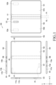
- FIG. 1 is a diagram illustrating an example electronic device in an unfolded state according to various embodiments.
- FIG. 2 is a diagram illustrating the electronic device in a folded state according to various embodiments.
- a configuration in which a pair of housings e.g., a first housing 101 and a second housing 102 are rotatably coupled to each other via a hinge module (e.g., the hinge module 204 of FIG. 3 ) may be illustrated.
- a hinge module e.g., the hinge module 204 of FIG. 3
- this embodiment does not limit the electronic device 100 according to various embodiments disclosed herein.
- the electronic device 100 according to various embodiments disclosed herein may include three or more housings, and "a pair of housings" in the embodiments disclosed below may refer to "two housings rotatably coupled to each other among three or more housings".
- the "front surface” or “rear surface” of the electronic device 100 or the housings 101 and 102 may be referred to, in which, irrespective of a relative position (e.g., an unfolded state or a folded state) of the housings 101 and 102, the surface on which the flexible display 103 of FIG. 1 is disposed is defined as the "front surface” of the electronic device 100 (or the housings 101 and 102), and a surface facing away from the surface on which the flexible display 103 is disposed is defined as the "rear surface” of the electronic device 100 (or the housings 101 and 102).
- the electronic device 100 includes a pair of housings 101 and 102, a flexible display 103, and a hinge module (e.g., the hinge modules 204 in FIG. 3 ) that rotatably connects the housings 101 and 102.
- the electronic device 100 may further include a hinge cover(s) 199 disposed on the upper end and/or the lower end.
- the hinge cover(s) 199 may be disposed substantially between the first housing 101 and the second housing 102, and may block the hinge module 204 from being visible to the outside.
- the hinge cover(s) 199 may isolate an internal space of the electronic device 100 from an external space.
- the hinge cover(s) 199 may be visible to the outside in the state in which the electronic device 100 is unfolded, and may be visually hidden in the folded state of the electronic device 100.
- the flexible display 103 may output a screen substantially in one direction (e.g., the +Z direction) through the entire area thereof.
- a first area A1 of the flexible display 103 is oriented in the +Z direction
- a second area A2 of the flexible display 103 is oriented in the -Z direction.
- the flexible display 103 may include areas (e.g., the first area A1 and the second area A2) arranged to face opposite directions in the state in which the electronic device 100 is folded.
- the first housing 101 and the second housing 102 may be rotated between a position in which the first and second housings are unfolded so as to be arranged side by side and a position in which the first and second housings are folded to face each other.
- the flexible display 103 may include a folding area A3, and in the folded state of the electronic device 100, the folding area A3 may be disposed to substantially face the +X direction.
- the flexible display 103 may be visible to the outside.
- the first housing 101 and/or the second housing 102 may accommodate the flexible display 103 on the front surfaces thereof, and may include rear plates 101b and 102b (e.g., the first rear plate 201b and the second rear plate 202b in FIG. 3 ) disposed on the rear surfaces thereof.
- the electronic device 100 may include a plurality of electrical components disposed in the space between the flexible display 103 and the rear plates 101b and 102b (e.g., a circuit board, various sensor modules, a battery, a sound input/output module, a camera module, a haptic module, an antenna, and/or a connection terminal).
- the first housing 101 may be coupled to the hinge module 204 to be rotatable about a first rotation axis P1
- the second housing 102 may be coupled to the hinge module 204 to be rotatable about a second rotation axis P2.
- the first housing 101 and the second housing 102 may be disposed to be substantially symmetrical to each other about the hinge module 204.
- the second housing 102 may rotate in a direction reverse to that of the first housing 101 so that the electronic device can be folded or unfolded.
- the flexible display 103 includes a first area A1 disposed on one surface of the first housing 101, a folding area A3 disposed to correspond to the hinge module 204, and/or a second area A2 disposed on one surface of the second housing 102.
- the flexible display 103 is disposed or extended from one surface of the first housing 101 across an area in which the hinge module 204 is disposed to reach one surface of the second housing 102.
- the first area A1 may be fixed to the first housing 101
- the second area A2 may be fixed to the second housing 102
- the folding area A3 may be supported by the multi-bar assembly (e.g., the multi-bar assembly 206 in FIG. 3 ).
- the multi-bar assembly 206 is disposed between the first housing 101 and the second housing 102 on the front surface of the electronic device 100 so as to support the flexible display 103 (e.g., the folding area A3).
- the flexible display 103 may output a screen through an area substantially corresponding to the total area of the front surface of the electronic device 100.
- the width measured from the side surface of the first housing 101 to the side surface of the second housing 102 in the X-axis direction in the unfolded state across the position at which the hinge module 204 is disposed may be substantially the same on the front surface of the electronic device 100 (e.g., the flexible display 103) and the rear surface of the electronic device 100.
- the width measured from the side surface of the first housing 101 to the side surface of the second housing 102 in the X-axis direction in the folded state across the position at which the hinge module 204 is disposed may be smaller on the rear surface of the electronic device 100 than on the front surface of the electronic device 100 (e.g., the flexible display 103).
- the first area A1 and the second area A2 of the flexible display 103 are fixed to the first housing 101 and the second housing 102 and the width measured in the X-axis direction cannot be substantially changed in the flexible display 103.
- the width measured in the X-axis direction on the rear surface of the electronic device 100 is changeable. For example, it is possible to implement a change in width measured in the X-axis direction on the rear surface of the electronic device 100 by causing a partial area (e.g., the area indicated by "V1" and/or the area indicated by "V2”) on the rear surface of the electronic device 100 to contract or expand.
- the width measured in the X-axis direction is changeable.
- the change in length of the rear surface of the electronic device 100 according to the unfolding or folding operation may be variously achieved.
- the change in the length of the rear surface of the electronic device 100 according to an unfolding or folding operation may be proportional to the distance between the flexible display 103 and the rear surface of the electronic device 100. For example, as the thickness of the electronic device 100 measured in the Z direction increases, the change in the length of the rear surface of the electronic device 100 according to the unfolding or folding operation may increase.
- the electronic device 100 may include at least one sensor area S 1 or S2 provided with at least one sensor module.
- the electronic device 100 may include a first sensor area S 1 provided on the front or side surface of the first housing 101 and/or a second sensor area S2 provided on the front surface of the first housing 101.
- a fingerprint recognition sensor may be disposed in the first sensor area S 1, for example.
- the fingerprint recognition sensor may include, for example, an optical fingerprint recognition sensor or an ultrasonic fingerprint recognition sensor, and may be disposed on the side surface of the first housing 101 (or the second housing 102) or inside the flexible display 103.
- the electronic device 100 may include a sensor module provided in the second sensor area S2, for example, at least one of a camera module, a proximity sensor, an illuminance sensor, an iris recognition sensor, an ultrasonic sensor, and an indicator.
- the sensor module(s) may be disposed inside the flexible display 103.
- the electronic device 100 may include a notch portion protruding from the second sensor area S2 to the first area A1 of the flexible display 103.
- the notch portion may be a structure of the first housing 101 (or the second housing 102), and at least some of the sensor modules may be disposed in the notch portion.
- the notch portion may have a polygonal shape, a circular shape, or an elliptical shape.
- the flexible display 103 in the second sensor area S2, may include a transparent area that allows external light to be incident therein.
- an optical sensor such as a camera module or a proximity sensor, may be disposed to correspond to the transparent area of the flexible display 103.
- the electronic device 100 (e.g., the sensor areas S 1 and S2 or the sensor module) according to various embodiments disclosed herein is not limited to the above-described configuration. Depending on functions provided in the electronic device 100 or functions of respective sensor modules mounted in the electronic device 100, the electronic device 100 may further include an additional sensor area or an additional sensor module. In various embodiments, the electronic device 100 may not include some of the above-mentioned sensor modules.
- the electronic device 100 may include a camera module 121 disposed on the rear surface thereof (e.g., the rear surface of the second housing 102).
- the camera module 121 may be interpreted as one of sensor modules, and may include a plurality of cameras, at least one infrared projector, at least one infrared receiver, or a flash.
- the user may photograph a subject using the camera module 121 provided on the rear surface of the electronic device 100 (e.g., the second housing 102).
- the camera module 121 may be disposed at another position, for example, a position indicated by reference numeral "123a" or "123b", and the electronic device 100 may further include an additional camera module or sensor module at a position different from the positions indicated in FIG. 1 .
- the electronic device 100 may include one or more key input devices 111a and 111b disposed on a side surface of the first housing 101 (and/or the second housing 102).
- the key input devices 111a and 111b may include, for example, a volume control key 111a and/or a power key 111b, and the illustrated key input devices 111a and 111b may be omitted or an additional key input device may be provided according to an embodiment.
- the electronic device 100 may further include a soft key provided through the flexible display 103.
- the electronic device 100 may include one or more connector holes 113a and 113b disposed in a side surface (e.g., a side surface, an upper surface, and/or a lower surface of the first housing 101 and/or the second housing 102).
- the connector holes 113a and 113b may include, for example, a first connector hole 113a for connecting a charging/data cable, and a second connector hole 113b for connecting a sound device (e.g., earphone).
- the data cable may refer to a cable provided to the sound device.
- the second connector hole 113b may be omitted from the electronic device 100, and the electronic device 100 may be connected to the sound device via the first connector hole 113a.
- the electronic device 100 may not include the connector holes 113a and 113b.
- the electronic device 100 may include functions such as wireless charging, Bluetooth communication, wireless fidelity (Wi-Fi) direct, or infrared data association (IrDA) so as to be connected to another electronic device or an additional device, such as an earphone, in a wireless manner.
- functions such as wireless charging, Bluetooth communication, wireless fidelity (Wi-Fi) direct, or infrared data association (IrDA) so as to be connected to another electronic device or an additional device, such as an earphone, in a wireless manner.
- Wi-Fi wireless fidelity
- IrDA infrared data association
- the electronic device 100 may include a plurality of sound output holes 115a and 115b and a plurality of sound input holes 117a and 117b.
- the sound output holes 115a and 115b may be disposed at the upper end and the lower end of the first housing 101 (and/or the second housing 102), respectively.
- the sound output holes 115a and 115b may be disposed in the side surface of the first housing 101 and the side surface of the second housing 102, respectively.
- the sound input holes 117a and 117b may be disposed at the upper and lower ends of the electronic device 100 (e.g., the first housing 101), respectively.
- the electronic device 100 may perform, in a voice call or sound recording mode, functions, such as a sound beam forming function, an active noise canceling (ANC) function, an echo canceling (EC) function, a noise suppression (NS) function, and/or a feedforward (FF) function by acquiring external sound through the plurality of sound input holes 117a and 117b.
- a sound input hole (not illustrated) may be further disposed in the rear surface of the first housing 101 (and/or the second housing 102).
- the electronic device 100 may acquire, in a photographing mode, external sound through the sound input hole disposed in the rear surface of the first housing 101.
- the electronic device 100 is capable of providing improved performance in terms of the sound beam forming function, the active noise canceling (ANC) function, the echo canceling (EC) function, the noise suppression (NS) function and/or feedforward (FF) function.
- ANC active noise canceling
- EC echo canceling
- NS noise suppression
- FF feedforward
- the first housing 101 and the second housing 102 may be disposed to form a predetermined angle with respect to each other, for example, 180 degrees.
- the flexible display 103 may output a screen in the +Z direction through substantially the entire area.
- the first housing 101 and the second housing 102 may be unfolded in an inclined form between a folded position facing each other and a predetermined angular position.
- the first area A1 and the second area A2 of the flexible display 103 may output screens in different directions.
- the electronic device 100 may provide a screen to two users who sit facing each other.
- the screen output from the first area A1 and the screen output from the second area A2 may be the same or different from each other.
- the flexible display 103 in the folded state, may be substantially visible to the outside.
- the electronic device 100 may output a screen using the first area A1, the second area A2, and/or the folding area A3.
- the electronic device 100 in the standby mode, may deactivate the screen of the flexible display 103 and may activate a partial area according to predetermined setting.
- the electronic device 100 may at least partially activate the first area A1 to output daily information, such as time or weather.
- the electronic device 100 may activate at least one of the first area A1, the second area A2, and/or the folding area A3 so as to provide visual information about the operating state or display notification information, such as messages or news.
- the radius of curvature of the folding area A3 of the flexible display 103 may vary while the electronic device 100 is being folded or unfolded. For example, as the electronic device 100 is gradually unfolded from the folded state, the radius of curvature of the folding area A3 may gradually increase. In the folding or unfolding operation, the electronic device 100 may adjust a screen output through the folding area A3. For example, by adjusting the aspect ratio of the screen in the folding area A3 according to the change in the radius of curvature, the electronic device 100 may compensate for the distortion of the output screen due to the deformation of the folding area A3.
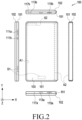
- FIG. 3 is an exploded perspective view illustrating an electronic device 200 (e.g., the electronic device 100 in FIG. 1 or FIG. 2 ) according to various embodiments.
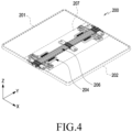
- FIG. 4 is a partial perspective view illustrating a structure in which the first housing 201 and the second housing 202 are connected to each other in the electronic device 200 (e.g., the electronic device 100 in FIG. 1 or FIG. 2 ) according to various embodiments.
- the electronic device 200 (e.g., the electronic device 100 of FIG. 1 or FIG. 2 ) includes a first housing 201 (e.g., the first housing 101 in FIG. 1 or FIG. 2 ), a second housing 202 (e.g., the second housing 102 of FIG. 1 or FIG. 2 ) rotatably connected to the first housing 201, at least one hinge module 204 rotatably connecting the first housing 201 and the second housing 202 to each other, and/or a flexible display 203 (e.g., the flexible display 103 of FIG. 1 or FIG. 2 ).
- the flexible display 203 is disposed to reach one surface (e.g., the front surface) of the second housing 202 from one surface (e.g., the front surface) of the first housing 201 across the area in which the hinge module 204 is disposed.
- the first housing 201 may include a first housing member 201a and a first rear plate 201b coupled to the first housing member 201a.
- the second housing 202 may include a second housing member 202a and a second rear plate 202b coupled to the second housing member 202a.
- the first housing 201 and the second housing 202 may have substantially the same structure, and may be partially different from each other according to electrical components disposed on each of the housings. For example, when the camera module 121 of FIG.
- first housing 201 and the second housing 202 are disposed in one of the first housing 201 and the second housing 202, the shapes of the first housing 201 and the second housing 202 (e.g., the first rear plate 201b and the second rear plate 202b) or the mechanical structures of the first housing member 201a and the second housing member 202a may be slightly different from each other.
- the difference between the first housing 201 and the second housing 202 may vary depending on an actually manufactured product.
- the first housing member 201a substantially forms the exterior of the electronic device 200 (e.g., the first housing 201), and may include a first side bezel structure 211 and a first support plate 213.
- the first side bezel structure 211 may have a frame shape that defines a side surface (e.g., the left side surface in FIG. 1 ), an upper surface, and/or a lower surface of the first housing 101, and may be open in a direction adjacent to the second housing 202.
- the first side bezel structure 211 may include a metal and/or a polymer, and may be electrically connected to a processor or a communication module of the electronic device 200 according to an embodiment.
- the first side bezel structure 211 may function as an antenna of the electronic device 200 by at least partially including a metal and/or an electrically conductive material.
- the first side bezel structure 211 may provide a decorative effect on the exterior of the electronic device 200 or provide an electrically insulating structure by including various coating layers.
- the first support plate 213 may be disposed in the space between the flexible display 203 and the first rear plate 201b and may be connected to the first side bezel structure 211.
- the first support plate 213 may be integrated with the first side bezel structure 211, and may include the same material as the first side bezel structure 211, for example, a metal and/or a polymer.
- the first support plate 213 may provide an electromagnetic shielding structure inside the electronic device 200 by including a metal and/or a conductive material.
- the first support plate 213 may function as a ground conductor providing a reference potential inside the electronic device 200 by including a metal and/or a conductive material.
- a flexible display 203 e.g., the first area A1 may be positioned on the outer surface of the first support plate 213.
- the first rear plate 201b may be made of, for example, coated or colored glass, ceramic, a polymer, a metal (e.g., aluminum, stainless steel (STS), or magnesium), or a combination of at least two of above-mentioned materials.
- the first rear plate 201b may be substantially integrated with the first housing member 201a (e.g., the first side bezel structure 211).
- at least a portion of the first rear plate 201b may include a curved area.
- an edge portion of the first rear plate 201b adjacent to the first side bezel structure 211 may be bent towards the front surface of the electronic device 200 (e.g., the surface on which the flexible display 203 is disposed) so as to include a seamlessly extending portion.
- the first rear plate 201b may be disposed to be inclined with respect to the first area A1 of the flexible display 203. For example, when the edge of the first rear plate 201b adjacent to the second housing 202 is located at a first height from the first area A1 of the flexible display 203, the end of the first rear plate 201b in the -X direction may be located at a second height lower than the first height.
- the space between the first support plate 213 and the first rear plate 201b may be at least partially surrounded by the first side bezel structure 211.
- the electronic device 200 may accommodate various electric components, such as a printed circuit board, a battery, a haptic module, a camera module, a sensor module(s) and/or a connection terminal.
- the first support plate 213 may be used as a structure that prevents and/or reduces other electrical components of the electronic device 200 from coming into contact with the flexible display 203.
- a camera module e.g., the camera module 121 in FIG.
- the description "exposed to the external space” may refer to including a configuration that is isolated from the external space but is visible and/or a configuration that is exposed so that a user is capable of directly touching it.
- a processor, a memory and/or an interface may be located on the printed circuit board.
- the processor may include various processing circuitry including, for example, and without limitation, at least one of a central processing unit, an application processor, a graphics processor, an image signal processor, a sensor hub processor, or a communication processor, or the like.
- the battery is a device for supplying power to at least one component of the electronic device 200, and may include, for example, a non-rechargeable primary battery, a rechargeable secondary battery, or a fuel cell. At least a portion of the battery may be disposed, for example, between the first support plate and the first rear plate to be substantially flush with the printed circuit board.
- the battery may be integrally disposed inside the electronic device 200, or may be detachably disposed on the electronic device 200.
- an additional support plate and/or an antenna may be provided in the space between the first support plate 213 and the first rear plate 201b.
- the additional support plate may improve the mechanical rigidity of the electronic device 200, and may provide an electromagnetic shielding structure between electrical components inside the electronic device 200.
- the antenna may be disposed between the first support plate 213 (and/or an additional support plate (not illustrated)) and the first rear plate 201b.
- the antenna may perform short-range communication with an external device or wirelessly transmitting and receiving power required for charging by including, for example, a near field communication (NFC) antenna, a wireless charging antenna, and/or a magnetic secure transmission (MST) antenna.
- the antenna structure may include a part of the first side bezel structure 211 and/or the first support plate 213 or a combination thereof.
- the second housing 202 may include a second housing member 202a (e.g., the second side bezel structure 221 and a second support plate 223) and a second rear plate 202b, and may have a structure similar to the structure of the first housing 201. Therefore, a detailed description thereof will be omitted.
- the electrical components disposed in the first housing 201 and/or the second housing 202 such as the key input devices 111a and 111b of FIG. 1 , the sensor areas S1 and S2, and/or the camera modules 121 may be different from each other.
- the second housing 202 may be partially different from the first housing 201 in shape or structure.
- the hinge module 204 rotatably couples the second housing 202 to the first housing 201.
- the first housing 201 may be coupled to the hinge module 204 to be rotatable about the first rotation axis P1
- the second housing 202 may be coupled to the hinge module 204 to be rotatable about the second rotation axis P2.
- the first housing 201 and the second housing 202 may be folded by rotating in the opposite direction with respect to each other in the unfolded state. In the folded state, the first housing 201 and the second housing 202 may be rotated in opposite directions with respect to each other to be unfold to a predetermined or specified angle.
- the "predetermined angle” may refer, for example, to an angle of 180 degrees.
- the hinge module 204 may link the rotation of the second housing 202 with the rotation of the first housing 201. For example, when the first housing 201 rotates in the first direction (e.g., clockwise when viewed from the state illustrated in FIG. 3 ) about the first rotation axis P1, the hinge module 204 may rotate the second housing 202 in a second direction (e.g., counterclockwise when viewed in the state illustrated in FIG. 3 ) that is opposite to the first direction. According to an embodiment, the hinge module 204 may provide a friction force when the first housing 201 and/or the second housing 202 rotate.
- first direction e.g., clockwise when viewed from the state illustrated in FIG. 3
- the hinge module 204 may rotate the second housing 202 in a second direction (e.g., counterclockwise when viewed in the state illustrated in FIG. 3 ) that is opposite to the first direction.
- the hinge module 204 may provide a friction force when the first housing 201 and/or the second housing 202 rotate.
- the hinge module 204 may allow the first housing 201 and/or the second housing 202 to rotate, and when the external force is not applied, the hinge module 204 may maintain the first housing 201 and/or the second housing 202 in the stationary state.
- the hinge module 204 may maintain the first housing 201 and/or the second housing 202 at a predetermined angular position (e.g., a folded 0 degree angular position, an unfolded 180 degree angular position and/or a position unfolded in an inclined form at an angle of about 120 degrees to 160 degrees) in a stationary state using a detent structure.
- the flexible display 203 may include a display panel 231 and a display protection layer 233.
- the display panel 231 may include a light-emitting layer disposed between transparent substrates, and the transparent substrates may include electric circuits such as a touch sensor.
- the display panel 231 may be made of, for example, an organic-light emitting diode (OLED) or a micro LED to output visual information, and to detect the user's direct contact with the display panel 231 or the user's motion performed within a predetermined distance from the display panel 231.
- OLED organic-light emitting diode
- the display protection layer 233 may attach the display panel 231 to the first housing 201 and/or the second housing 202, and may be made of an elastic material so as to be used as a cushioning material between the display panel 231 and mechanical structures (e.g., the first housing 201 and/or the second housing 202).
- the flexible display 203 may include a first area A1 mounted on or fixed to the first housing 201, a second area A2 located in the second housing 202, and a folding area A3 connecting the first area A1 and the second area A2.
- the folding area A3 is disposed to substantially correspond to the area in which the hinge module 204 is disposed, and may be deformed into a flat shape or a curved shape while the electronic device 200 (e.g., the electronic device 100 in FIG. 1 or FIG. 2 ) is being folded or unfolded.
- the flexible display 203 may output a screen in one direction using substantially the entire area.
- the flexible display 203 may output screens in different directions using the first area A1 and the second area A2.
- the electronic device 200 may further include a first slide plate 205a and a second slide plate 205b.
- the first slide plate 205a may be located on the first housing member 201a (e.g., the first support plate 213), and a portion of the hinge module 204 may be slidably coupled between the first support plate 213 and the first slide plate 205a.
- the second slide plate 205b may be located on the second housing member 201a (e.g., the second support plate 223), and a portion of the hinge module 204 may be slidably coupled between the second support plate 223 and the second slide plate 205b.
- first slide plate 205a and the second slide plate 205b couple the first housing 201 and/or the second housing 202 to the hinge module 204 so as to guide or support the sliding movement of the first housing 201 and/or the second housing 202.
- first slide plate 205a and/or the second slide plate 205b may not be included in the electronic device 200.
- the electronic device 200 (e.g., the electronic device 100 in FIG. 1 or FIG. 2 ) further includes a multi-bar assembly 206 and may include an elastic sheet 207 disposed between the flexible display 203 and the multi-bar assembly 206 so as to support the flexible display 203.
- the multi-bar assembly 206 may be disposed to correspond to an area in which the hinge module 204 is disposed, and may connect the first support plate 213 and the second support plate 223 to each other.
- the multi-bar assembly 206 and the elastic sheet 207 may be disposed to support the folding area A3 of the flexible display 203.
- the multi-bar assembly 206 may include a plurality of (e.g., five) bars or rods extending in one direction.
- the bars or rods of the multi-bar assembly 206 may, for example, have a circular, oval, or polygonal cross section, and are disposed parallel to the longitudinal direction Y of the electronic device 200, for example, the rotation axis P1 or P2.
- the plurality of bars or rods may be arranged in the width direction of the electronic device 200 (X-axis direction) to be rotatably connected to other adjacent bars or rods. By rotating the bars or rods with respect to other adjacent bars or rods, the multi-bar assembly 206 may be deformed into a flat plate shape and/or a curved shape.
- the multi-bar assembly 206 and the elastic sheet 207 are capable of supporting the folding area A3 of the flexible display 203 while being deformed to correspond to the folding area A3.
- the multi-bar assembly 206 is capable of supporting the folding area A3 to suppress the deformation of the folding area A3.
- FIG. 5 is an exploded perspective view illustrating an example multi-bar assembly (e.g., the multi-bar assembly 206 in FIGS. 3 and 4 ) and an elastic sheet 207 in an electronic device (e.g., the electronic device 200 in FIGS. 3 and 4 ) according to various embodiments.
- FIG. 6 is an exploded perspective view illustrating the multi-bar assembly (e.g., the multi-bar assembly 206 in FIGS. 3 and 4 ) in an electronic device (e.g., the electronic device 200 in FIGS. 3 and 4 ) according to various embodiments.
- the multi-bar assembly 206 is connected to the hinge module 204 to be variable on the basis of the movement of the hinge module 204.
- the elastic sheet 207 may be disposed on the multi-bar assembly 206 to be variable in response to the variable operation of the multi-bar assembly 206.
- the multi-bar assembly 206 may include a center bar 530 and multi-bars 540.
- the configurations of the center bar 530 and the multi-bars 540 of FIGS. 5 and 6 may be entirely or partially the same as the configurations of the bars or rods of the multi-bar assembly 206 of FIGS. 3 and 4 .
- the center bar 530 may support a flexible display (e.g., the flexible display 203 in FIGS. 3 and 4 ) together with the multi-bars 540.
- the center bar 530 may be connected to the hinge cover 310.
- the center bar 530 may be inserted into a groove located in a protruding area of the hinge cover 310.
- the center bar 530 may be disposed between a first rotation axis (e.g., the first rotation axis P1 in FIG. 3 ) and a second rotation axis (e.g., the second rotation axis P2 in FIG. 3 ).
- the center bar 530 may be connected to a plurality of hinge covers 310.
- one end of the center bar 530 may be connected to a first hinge cover 310-1 and the other end may be connected to a second hinge cover 310-2.
- the first hinge cover 310-1 may include a first hinge cover surface 310-1a on which a curved rail guide is disposed
- the second hinge cover 310-2 may include a second hinge cover surface 310-2a which faces the first hinge cover surface 310-la and on which a curved rail guide is disposed.
- a plurality of bars (multi-bars) 540 may be provided.
- the multi-bars 540 may be disposed on opposite sides of the center bar 530, and may be located to face the folding area (e.g., the folding area A3 in FIG. 1 ).
- two multi-bars 540 may be disposed on each side of the center bar 530.
- the multi-bar assembly 206 may include a plurality of bar support holders 430 and 440 and bar support brackets 410 and 420.
- first bar support holders 430 of the multi-bar assembly 206 are capable of connecting first rotation brackets 331 to the first housing (e.g., the first housing 201 in FIGS. 3 and 4 ), and second bar support holders 440 may connect second rotation brackets 341 to the second housing (e.g., the second housing 202 in FIGS. 3 and 4 ).
- the first housing 201 is connected to the first rotation brackets 331 via the first bar support holders 430 so as to rotate according to the movement of the first rotation brackets 331, and the second housing 202 may be connected to the second rotation brackets 341 via the second bar support holders 440 so as to rotate according to the movement of the second rotation brackets 341.
- the first bar support holders 430 may be connected to some of the multi-bars 540, and the second bar support holders 440 may be connected to remaining ones of the multi-bars 540.
- the bar support brackets 410 and 420 may include center bar support brackets 410 configured to support the center bar 530 and multi-bar support brackets 420 configured to support the multi-bars 540.
- the center bar 530 is coupled to the foldable housing (e.g., the foldable housing 300 of FIG. 1 ) via the center bar support brackets 410
- the multi-bars 540 may be coupled to the foldable housing 300 via the multi-bar support brackets 420.
- the configurations of the bar support brackets 410 and 420 will be described in greater detail.
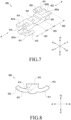
- FIG. 7 is a perspective view illustrating an example bar support bracket 600 (e.g., the bar support bracket 410 or 420 in FIGS. 5 and 6 ) in a multi-bar assembly (e.g., the multi-bar assembly 206 in FIGS. 5 and 6 ) of an electronic device (e.g., the electronic device 200 in FIGS. 3 and 4 ) according to various embodiments.
- FIG. 8 is a side view of the bar support bracket 600 of FIG. 7 when viewed in the direction A according to various embodiments.
- the direction A may refer to a direction oriented in the -Y axis direction in the Cartesian coordinate system.
- the multi-bar assembly may include a plurality of bars (e.g., the center bar 530 and the multi-bars 540 in FIGS. 5 and 6 ), bar support brackets 600 (e.g., the bar support brackets 410 and 420 in FIGS. 5 and 6 ), and bar support holders (e.g., the bar support holders 430 and 440 in FIGS. 5 and 6 ) disposed on opposite sides of each bar support bracket 600.
- the plurality of bars may include a center bar (e.g., the center bar 530 in FIGS. 5 and 6 ) and multi-bars (e.g., the multi-bars 540 in FIGS.
- the bar support brackets 600 may include center bar support brackets configured to support the center bar 530 (e.g., the center bar support brackets 410 in FIGS. 5 and 6 ), and multi-bar support brackets configured to support the multi-bars 540 (e.g., the multi-bar support brackets 420 of FIGS. 5 and 6 ).
- the shapes of the center bar support brackets 410 and the multi-bar support brackets 420 may be the same.
- each bar support bracket 600 may include a central portion 603 in which a fastening hole 631 is disposed, a first portion 601 extending from the central portion 603 in the +Y-axis direction, and a second portion 602 extending from the central portion 603 in the -Y-axis direction opposite to the +Y-axis direction.
- the +Y-axis direction and/or the - Y-axis direction may be parallel to the longitudinal direction of the plurality of bars.
- the structure of the first portion 601 and the structure of the second portion 602 may be implemented in shapes corresponding to each other.
- the second portion 602 may have the same structure as the first portion 601, but the second portion 602 takes a form in which the left and right sides thereof are inverted with respect to the first portion 601.
- the central portion 603 of the bar support bracket 600 has a plate shape and connects the first portion 601 and the second portion 602.
- the central portion 603 may include at least one fastening hole 631 disposed in the upper surface thereof, for example, the surface oriented in the +Z-axis direction.
- the at least one fastening hole 631 may include, for example, a thread formed in the inner wall thereof, and may provide a means to allow the bar support bracket 600 to be positioned in the multi-bar assembly 206 (e.g., each of the bars).
- each of the bars of the multi-bar assembly 206 may include a fastening boss corresponding to the fastening hole 631.
- the first portion 601 of the bar support bracket 600 may include an extension 601a extending in the +Y-axis direction from the central portion 603 and a protrusion 601b protruding from the extension 601a in a direction perpendicular to the +Y axis.
- the extension 601a may include a (1-1)th rail guide 613 and a (1-1)th rail guide stopper 614
- the protrusion 601b may include a (1-1)th rail 611 and a (1-1)th rail stopper 612.
- the (1-1)th rail 611, the (1-1)th rail stopper 612, the (1-1)th rail guide 613, and the (1-1)th rail guide stopper 614 may have an integrated structure made of the same material.
- the (1-1)th rail 611 may protrude in a direction (e.g., +X-axis direction) perpendicular to the longitudinal direction (e.g., +Y/-Y-axis direction) of the bar support bracket 600. At least a portion of the (1-1)th rail 611 may include a curved structure. For example, the (1-1)th rail 611 may have a curved rail structure.
- the (1-1)th rail 611 When the bar support bracket 600 is viewed in the direction A, the (1-1)th rail 611 has an upper surface (e.g., the surface oriented in the +Z direction) and a lower surface (e.g., the surface oriented in the -Z direction) may be configured in curved surfaces parallel to each other, and may provide a curved structure convex downwards, for example, in the -Z direction.
- the (1-1)th rail 611 may be a portion to be slid along a rail guide of a bar support bracket adjacent thereto.
- the (1-1)th rail stopper 612 protrudes in the longitudinal direction of the bar support bracket 600 from the end of the (1-1)th rail 611, and at least a portion of the (1-1)th rail stopper 612 may include a curved structure.
- the (1-1)th rail stopper 612 may have a structure protruding in the -Y-axis direction, and may be a portion configured to prevent and/or reduce the (1-1)th rail 611 from sliding beyond a predetermined distance.
- the curved structure of the (1-1)th rail stopper 612 is manufactured in a shape corresponding to the (1-1)th rail guide stopper 614 disposed at the end of the (1-1)th rail guide 613.
- the (1-1)th rail stopper 612 comes into contact with the rail guide stopper of the bar support bracket adjacent thereto, the (1-1)th rail stopper 612 and the rail guide stopper are stably fitted to each other, and the sliding movement of the (1-1)th rail 611 can be stopped.
- the (1-1)th rail guide 613 may have a recess shape (or a through hole shape with one open side) extending from the upper surface (e.g., the surface oriented in the +Z direction) of the first portion 601 towards the side surface (e.g., the surface oriented in the -X direction) of the first portion 601 and penetrating the inside of the first portion 601.
- the recess shape (or the through hole shape) may be implemented to correspond to the curved shape of the (1-1)th rail 611 so as to guide the rail of the bar support bracket adjacent thereto to stably slide along a bent line in the (1-1)th rail guide 613.
- the (1-1)th rail guide stopper 614 protrudes in the longitudinal direction of the bar support bracket 600 from the inner end of the (1-1)th rail guide 613, and at least a portion of the (1-1)th rail guide stopper 614 may include a curved structure.
- the (1-1)th rail guide stopper 614 has a structure protruding in the +Y-axis direction, and may suppress the movement of the rail that slides in the (1-1)th rail guide 613.
- the curved structure of the (1-1)th rail guide stopper 614 is manufactured to have a shape corresponding to the (1-1)th rail stopper 612.
- the (1-1)th rail guide stopper 614 comes into contact with the rail stopper adjacent thereto, the (1-1)th rail guide stopper 614 and the rail stopper are stably fitted to each other, and the sliding movement of the rail moving in the (1-1)th rail guide can be stopped.
- the second portion 602 of the bar support bracket 600 may include an extension 602a extending in the -Y-axis direction from the central portion 603 and a protrusion 602b protruding from the extension 602a in a direction perpendicular to the -Y axis.
- the extension 602a may include a (1-2)th rail guide 623 and a (1-2)th rail guide stopper 624
- the protrusion 602b may include a (1-2)th rail 621 and a (1-2)th rail stopper 622.
- the (1-2)th rail 621, the (1-2)th rail stopper 622, the (1-2)th rail guide 623, and the (1-2)th rail guide stopper 624 may have an integrated structure made of the same material.
- the bar support bracket 600 is integrally configured as a whole, and the central portion 603, the first portion 601, and the second portion 602 may be made of the same material.
- the (1-2)th rail 621 may protrude in a direction perpendicular to the longitudinal direction of the bar support bracket 600. At least a portion of the (1-2)th rail 621 may include a curved structure.
- the (1-2)th rail 621 may have a structure that protrudes in the opposite direction to the (1-1)th rail 611.
- the (1-2)th rail 621 may have a curved rail structure.
- the (1-2)th rail 621 When the bar support bracket 600 is viewed in the A' direction, the (1-2)th rail 621 has an upper surface (e.g., the surface oriented in the +Z direction) and a lower surface (e.g., the surface oriented in the +Z direction) may be configured in curved surfaces parallel to each other, and may provide a curved structure convex downwards, for example, in the -Z direction.
- the (1-2)th rail 621 may be a portion to be slid along a rail guide of a bar support bracket adjacent thereto.
- the (1-2)th rail stopper 622 protrudes in the longitudinal direction of the bar support bracket 600 from the end of the (1-2)th rail 621, and at least a portion of the (1-2)th rail stopper 612 may include a curved structure.
- the (1-2)th rail stopper 622 may have a structure protruding in the +Y-axis direction, and may be a portion configured to prevent and/or reduce the (1-2)th rail 621 from sliding beyond a predetermined distance.
- the curved structure of the (1-2)th rail stopper 622 is manufactured in a shape corresponding to the (1-2)th rail guide stopper 624 disposed at the end of the (1-2)th rail guide 623.
- the (1-2)th rail guide 623 may have a recess shape (or a through hole shape with one open side) extending from the upper surface (e.g., the surface oriented in the +Z direction) of the second portion 602 towards the side surface (e.g., the surface oriented in the +X direction) of the first portion 602 and penetrating the inside of the second portion 602.
- the recess shape (or the through hole shape) may be implemented to correspond to the curved shape of the (1-2)th rail 621 so as to guide the rail of the bar support bracket adjacent thereto to stably slide along a bent line in the (1-2)th rail guide 623.
- the (1-2)th rail guide stopper 624 protrudes in the longitudinal direction of the bar support bracket 600 from the inner end of the (1-2)th rail guide 623, and at least a portion of the (1-1)th rail guide stopper 614 may include a curved structure.
- the (1-2)th rail guide stopper 624 has a structure protruding in the -Y-axis direction, and may suppress the movement of the rail that slides in the (1-2)th rail guide 623.
- the curved structure of the (1-2)th rail guide stopper 624 is manufactured to have a shape corresponding to the (1-2)th rail stopper 622.
- FIG. 9 is a perspective view illustrating a plurality of support brackets 600a and 600b disposed adjacent to each other in a multi-bar assembly (e.g., the multi-bar assembly 206 in FIGS. 3 and 4 ) in an electronic device (e.g., the electronic device 200 in FIGS. 3 and 4 ) according to various embodiments.
- FIG. 10 is a side view illustrating the configuration, in which the plurality of adjacent bar support brackets 600a and 600b are coupled to each other, when viewed in the direction A in FIG. 9 according to various embodiments.
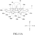
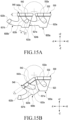
- FIGS. 11A , 11B and 11C are side views illustrating the rotational movement of a plurality of adjacent bar support brackets 600a and 600b according to various embodiments.
- the multi-bar assembly (e.g., the multi-bar assembly 206 in FIGS. 5 and 6 ) may include a plurality of bars (e.g., the center bar 530 and the multi-bars 540 in FIGS. 5 and 6 ), bar support brackets 600 (e.g., the bar support brackets 410 and 420 in FIGS. 5 and 6 ), and bar support holders (e.g., the bar support holders 430 and 440 in FIGS. 5 and 6 ) disposed on opposite sides of each bar support bracket 600.
- bars e.g., the center bar 530 and the multi-bars 540 in FIGS. 5 and 6
- bar support brackets 600 e.g., the bar support brackets 410 and 420 in FIGS. 5 and 6
- bar support holders e.g., the bar support holders 430 and 440 in FIGS. 5 and 6
- the bar support brackets 600a and 600b may include a center bar support bracket 600a configured to support a center bar 530 (e.g., the center bar support brackets 410 in FIGS. 5 and 6 ), and a multi-bar support bracket 600b configured to support a multi-bar 540 (e.g., the multi-bar support brackets 420 of FIGS. 5 and 6 ).
- the shapes of the center bar support bracket 600a and the multi-bar support bracket 600b may be the same.
- the multi-bar support bracket 600b may be disposed on the left side, and the center bar support bracket 600a and the multi-bar support bracket 600b may be coupled to each other so as to enable sliding and/or rotational movement with respect to each other.
- the structures of the center bar support bracket 600a and the multi-bar support bracket 600b may be entirely or partially the same as the structure of the bar support bracket 600 illustrated in FIGS. 7 and 8 .
- the center bar support bracket 600a may include a central portion 6031, a (1-1)th portion 6011 extending from the central portion 6031 in the +Y-axis direction, and a (1-2)th portion 6021 extending from the central portion 6031 in the -Y-axis direction opposite to the +Y-axis direction.
- the (1-1)th portion 6011 of the center bar support bracket 600a may include a (1-1)th rail 611a, a (1-1)th rail stopper 612a, a (1-1)th rail guide 613a, and a (1-1)th rail guide stopper 614a.
- the (1-2)th portion 6021 of the center bar support bracket 600a may include a (1-2)th rail 621a, a (1-2)th rail stopper 622a, a (1-2)th rail guide 623a, and a (1-2)th rail guide stopper 624a.
- the multi-bar support bracket 600b may include a central portion 6032, a (2-1)th portion 6012 extending from the central portion 6032 in the +Y-axis direction, and a (2-2)th portion 6022 extending from the central portion 603b in the -Y-axis direction opposite to the +Y-axis direction.
- the (2-1)th portion 6012 of the center bar support bracket 600a may include a (2-1)th rail 611b, a (2-1)th rail stopper 612b, a (2-1)th rail guide 613b, and a (2-1)th rail guide stopper 614b.
- the (2-2)th portion 6022 of the center bar support bracket 600a may include a (2-2)th rail 621b, a (2-2)th rail stopper 622b, and a (2-2)th rail guide 623b, and a (2-2)th rail guide stopper 624b.
- the center bar support bracket 600a and the multi-bar support bracket 600b may be rotatably coupled to each other.
- at least a portion of the (2-1)th portion 6012 of the multi-bar support bracket 600b may be coupled to at least a portion of the (1-1)th portion 6011 of the center bar support bracket 600a.
- the (2-1)th rail 611b (and/or the (2-1)th rail stopper 612b) of the multi-bar support bracket 600b may be assembled to be slidable in the (1-1)th rail guide (613a) of the center bar support bracket 600a.
- At least a portion of the (1-2)th portion 6021 of the center bar support bracket 600a may be coupled to at least a portion of the (2-2)th portion 6022 of the multi-bar support bracket 600b.
- the (1-2)th rail 621a (and/or the (1-2)th rail stopper 622a) of the center bar support bracket 600a may be assembled to be slidable in the (2-2)th rail guide 623b of the multi-bar support bracket 600b.
- each of the rails (e.g., the (1-1)th rail 611a and/or the (1-2)th rail 621a) of the center bar support bracket 600a may rotate with reference to one rotation axis
- each of the rails (e.g., the (2-1)th rail 611b and/or the (2-2)th rail 621b) of the multi-bar support bracket 600b may rotate with reference to another rotation axis.
- the center bar support bracket 600a and the multi-bar support bracket 600b may be assembled to each other such that the rotation axis of the (1-2)th rail 621a of the center bar support bracket 600a coincides with the rotation axis of the s(2-1)th rail 611b of the multi-bar support bracket 600b when the structure in which the center bar support bracket 600a and the multi-bar support bracket 600b are assembled to each other is viewed in the direction A.
- each of the rails e.g., the (1-1)th rail 611a and/or the (1-2)th rail 621a) of the center bar support bracket 600a and each of the rails (e.g., the (2-1)th rail 611b and/or the (2-2)th rail 621b) of the multi-bar support bracket 600b may rotate and slide.
- the multi-bar assembly 206 which supports the bending area of the flexible display (e.g., the flexible display 203 in FIG. 3 ) may define a curved surface corresponding to the bending area.
- FIGS. 11A to 11CA a description will be made of the rotational movement of the bar support brackets 600 that changes the flexible display 203 in a partial area of the bending area of the flexible display 203 when the electronic device is switched from the unfolded position to the folded position.
- the state in which the center bar support bracket 600a and the multi-bar support bracket 600b are arranged side by side is defined as a first state S1 (e.g., FIG. 11A ), the state in which the multi-bar support bracket 600b is rotating with respect to the center bar support bracket 600a is defined as a second state S2 (e.g., FIG. 11B ), and the state in which the rotation of the multi-bar support bracket 600b with respect to the center bar support bracket 600a is completed and side surfaces face each other may be defined as a third state S3 (e.g., FIG. 11C ).
- the upper surface of the center bar support bracket 600a for example, the surface oriented in the +Z direction may be set as a reference plane L1 (or a reference line).
- a first upper surface 615a of the center bar support bracket 600a and a second upper surface 615b of the multi-bar support bracket 600b may be disposed to be oriented in the same direction (e.g., the +Z-axis direction).
- the first upper surface 615a of the center bar support bracket 600a and the second upper surface 615b of the multi-bar support bracket 600b may coincide with the reference plane L1.
- one rail of the center bar support bracket 600a is located in one rail guide of the multi-bar support bracket 600b, and the other rail of the multi-bar support bracket 600b may be located in the other rail guide of the center bar support bracket 600a.
- the (1-2)th rail 621a of the center bar support bracket 600a is located in the (2-2)th rail guide 623b of the multi-bar support bracket 600b, the (1-2)th rail stopper 622a of the center bar support bracket 600a comes into contact with the (2-2)th rail guide stopper 624b of the multi-bar support bracket 600b so that the further rotation of the (1-2)th rail 621a is limited, and the first upper surface 615a of the center bar support bracket 600a and the second upper surface 615b of the multi-bar support bracket 600b are capable of maintaining 180 degrees.
- a first side surface 616a of the center bar support bracket 600a facing the multi-bar support bracket 600b and a second side surface 616b of the multi-bar support bracket 600b facing the center bar support bracket 600 are capable of being spaced apart from each other.
- the first side surface 616a and the second side surface 616b may set a predetermined first angle ⁇ 1 with reference to a rotation axis R1.
- the position of the multi-bar support bracket 600b with respect to the center bar support bracket 600a varies. Accordingly, the angle formed by the first side surface 616a and the second side surface 616b with reference to the rotation axis R1 may be reduced, and the maximum angle may be formed in the first state S1.
- the first upper surface 615a of the center bar support bracket 600a and the second upper surface 615b of the multi-bar support bracket 600b may be disposed to be oriented in different directions.
- the first upper surface 615a of the center bar support bracket 600a may define the reference plane L1
- the second upper surface 615b of the multi-bar support bracket 600b may be in the state of being rotated by a predetermined angle ⁇ 21 with respect to the reference plane L1.
- one rail of the center bar support bracket 600a is located in one rail guide of the multi-bar support bracket 600b, and one rail of the multi-bar support bracket 600b may be located in one rail guide of the center bar support bracket 600a.
- the second state S2 may be the state in which the rail of the center bar support bracket 600a (or the multi-bar support bracket 600b) performs a sliding operation to move along the rail guide of the multi-bar support bracket 600b (or the center bar support bracket 600a).
- the (1-2)th rails 621a of the center bar support bracket 600a is slidable along the (2-2)th rail guide 623b of the multi-bar support bracket 600b.
- the (1-2)th rail 621a is movable from the second side surface 616b of the multi-bar support bracket 600b towards the second upper surface 615b while being in contact with the curved surface of the (2-2)th rail guide 623b.
- the curved surface may be a part of an imaginary radius of curvature defined with respect to the rotation axis R1.
- the spacing distance may be smaller than that in the first state S1.
- the first side surface 616a and the second side surface 616b may set a predetermined second angle ⁇ 2 with reference to the rotation axis R1.
- the second angle ⁇ 2 may be smaller than the first angle ⁇ 1 in the first state (S1).
- the first upper surface 615a of the center bar support bracket 600a and the second upper surface 615b of the multi-bar support bracket 600b may be disposed to be oriented in different directions.
- the first upper surface 615a of the center bar support bracket 600a may define the reference plane L1
- the second upper surface 615b of the multi-bar support bracket 600b may be in the state of being rotated by a predetermined angle ⁇ 31 with respect to the reference plane L1.
- the rotated state of the third state S3 may be greater than the rotated state of the second state S2.
- one rail of the center bar support bracket 600a is located in one rail guide of the multi-bar support bracket 600b, and one rail of the multi-bar support bracket 600b may be located in one rail guide of the center bar support bracket 600a, or may at least partially protrude to the outside of the rail guide.
- at least a portion of the (1-2)th rail 621a of the center bar support bracket 600a may be located to be exposed to the outside of the (2-2)th rail guide 623b of the multi-bar support bracket 600b and to protrude from the second upper surface 615b.
- a first side surface 616a of the center bar support bracket 600a facing the multi-bar support bracket 600b and a second side surface 616b of the multi-bar support bracket 600b facing the center bar support bracket 600 may be located to be in contact with each other or to face each other.
- the first side surface 616a and the second side surface 616b may set a predetermined third angle ⁇ 3 with reference to the rotation axis R1.
- the position of the multi-bar support bracket 600b with respect to the center bar support bracket 600a varies. Accordingly, the angle formed by the first side surface 616a and the second side surface 616b with reference to the rotation axis R1 may be reduced, and the minimum angle (e.g., the angle of 0 degrees) may be formed in the third state S3.
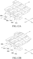
- FIGS. 12A, 12B and 12C are perspective views illustrating the rotational movement of a plurality of support brackets 600a, 600b, and 600c disposed adjacent to each other in a multi-bar assembly (e.g., the multi-bar assembly 206 in FIGS. 3 and 4 ) in an electronic device (e.g., the electronic device 200 in FIGS. 3 and 4 ) according to various embodiments.
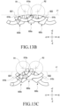
- FIGS. 13A , 13B and 13C are side views illustrating the rotational movement of a plurality of support brackets 600a, 600b, and 600c disposed adjacent to each other in a multi-bar assembly (e.g., the multi-bar assembly 206 in FIGS. 3 and 4 ) in an electronic device (e.g., the electronic device 200 in FIGS. 3 and 4 ) according to various embodiments.
- the multi-bar assembly (e.g., the multi-bar assembly 206 in FIGS. 5 and 6 ) may include a plurality of bars (e.g., the center bar 530 and the multi-bars 540 in FIGS. 5 and 6 ), bar support brackets 600 (e.g., the bar support brackets 410 and 420 in FIGS. 5 and 6 ), and bar support holders (e.g., the bar support holders 430 and 440 in FIGS. 5 and 6 ) disposed on opposite sides of each bar support bracket 600.
- bars e.g., the center bar 530 and the multi-bars 540 in FIGS. 5 and 6
- bar support brackets 600 e.g., the bar support brackets 410 and 420 in FIGS. 5 and 6
- bar support holders e.g., the bar support holders 430 and 440 in FIGS. 5 and 6
- the bar support brackets 600a, 600b, and 600c may include a center bar support bracket 600a configured to support a center bar 530 (e.g., the center bar support brackets 410 in FIGS. 5 and 6 ), and multi-bar support brackets 600b and 600c configured to support multi-bars 540 (e.g., the multi-bar support brackets 420 of FIGS. 5 and 6 ), respectively.
- the shapes of the center bar support bracket 600a and the multi-bar support brackets 600b and 600c may be the same.
- the multi-bar support bracket 600b may be disposed on the left side, and the center bar support bracket 600a and the multi-bar support bracket 600b may be coupled to each other so as to enable sliding and/or rotational movement with respect to each other.
- the second multi-bar support bracket 600c may be disposed on the right side, and the center bar support bracket 600a and the multi-bar support bracket 600c may be coupled to each other so as to enable sliding and/or rotational movement with respect to each other.
- the structures of the center bar support bracket 600a and the multi-bar support bracket 600b may be entirely or partially the same as the structure of the bar support bracket 600 illustrated in FIGS. 7 and 8 .
- the structure of the center bar support bracket 600a and the coupling and sliding structures of the multi-bar support bracket 600b of FIGS. 9 , 10 , 11A , 11B and 11C are applicable to the structure of the center bar support bracket 600a and the coupling and sliding structures of the first and second multi-bar support brackets 600b and 600c.
- respective rails of the center bar support bracket 600a may be located in the rail guide of the first multi-bar support bracket 600b and the rail guide of the second multi-bar support bracket 600c, and one rail of each of the first and second multi-bar support brackets 600b and 600c may be located in a rail guide of the center bar support bracket 600a.
- the rail 611b of the first multi-bar support bracket 600b may be coupled to be slidable along the rail guide 613a of the center bar support bracket 600a
- the rail 611a of the center bar support bracket 600a may be coupled to be slidable along the rail guide 613c of the second multi-bar support bracket 600c.
- the rail of the second multi-bar support bracket 600c may be coupled to be slidable along the rail guide of the center bar support bracket 600a, and the rail of the center bar support bracket 600a may be coupled to be slidable along the rail guide of the first multi-bar support bracket 600b.
- one rail of the center bar support bracket 600a and one rail of the first multi-bar support bracket 600b may rotate and slide with reference to the first rotation axis R1
- the other rail of the center bar support bracket 600a and one rail of the second multi-bar support bracket 600c may rotate and slide with reference to the second rotation axis R2.
- the upper surface 615a of the center bar support bracket 600a and the upper surfaces 615b and 615c of the first and second multi-bar support brackets 600b and 600c may be arranged side by side so as to be oriented in the same direction (e.g., the +Z-axis direction).
- the upper surface 615a of the center bar support bracket 600a and the upper surfaces 615b and 615c of the first and second multi-bar support brackets 600b and 600c may be arranged so as to be oriented in different directions.
- the upper surface of the center bar support bracket 600a may define a reference plane L1
- the upper surface of the first multi-bar support bracket 600b may be rotated by a predetermine angle ⁇ 21 with respect to the reference plane L1
- the upper surface of the second multi-bar support bracket 600c may be rotated by a predetermined angle ⁇ 22 with respect to the reference plane L1.
- the upper surface 615a of the center bar support bracket 600a and the upper surfaces of the first and second multi-bar support brackets 600b and 600c may be arranged so as to be oriented in different directions.
- the upper surface of the center bar support bracket 600a may define a reference plane L1
- the upper surface of the first multi-bar support bracket 600b may be rotated by a predetermine angle ⁇ 31 with respect to the reference plane L1
- the upper surface of the second multi-bar support bracket 600c may be rotated by a predetermined angle ⁇ 32 with respect to the reference plane L1.
- the angle by which the upper surfaces 615b and 615c of the first and second multi-bar support brackets 600b and 600c are rotated with respect to the reference plane L1 may be greater than the angle in the second state (S2).
- FIG. 14 is a diagram illustrating a state in which multi-bars are coupled to each other in a multi-bar assembly (e.g., the multi-bar assembly 206 in FIGS. 3 and 4 ) in an electronic device (e.g., the electronic device 200 in FIGS. 3 and 4 ) according to various embodiments.
- FIGS. 15A and 15B are side views illustrating a configuration in which a plurality of adjacent bar support brackets 600 and 600a and multi-bars 530 and 540 are coupled to each other according to various embodiments.
- the multi-bar assembly (e.g., the multi-bar assembly 206 in FIGS. 5 and 6 ) may include a plurality of bars 530 and 540 (e.g., the center bar 530 and the multi-bars 540 in FIGS. 5 and 6 ), and bar support brackets 600a and 600b (e.g., the bar support brackets 410 and 420 in FIGS. 5 and 6 ).
- the bar support brackets 600a and 600b may include a center bar support bracket 600a configured to support a center bar 530, and a multi-bar support bracket 600b configured to support a multi-bar 540 (e.g., the multi-bar support brackets 420 in FIGS. 5 and 6 ).
- the shapes of the center bar support bracket 600a and the multi-bar support bracket 600b may be the same.
- the shapes of the center bar 530 and the multi-bars 540 may be at least partially the same.
- the shapes of the center bar support bracket 600a and the multi-bar support bracket 600b may be at least partially the same.
- the center bar 530 may be positioned along the center line of the bending area to be capable of supporting the bending area of the flexible display (e.g., the flexible display 203 in FIG. 3 ). Opposite end portions of the center bar 530 in the +Y-axis/-Y-axis direction may be connected to the first hinge cover 310-1 and the second hinge cover 310-2.
- the center bar 530 may include a first line portion 531 and a first dummy portion(s) 532 located in end portions (e.g., the opposite end portions in the +Y axis/-Y axis direction) and/or the center of the first line portion 531.
- the first line portion 531 may have the same thickness and may be disposed parallel with the adjacent multi-bars 540.
- the first dummy portion 532 may include at least one first guide recess 532a and may have a greater width (e.g., the length in the +X-axis/-X-axis direction) than the first line portion 531.
- the first guide recess 532a may have one of the shapes of an opening penetrating at least a portion of the first dummy portion 532 and a groove defined in at least a partial surface of the first dummy portion 532.
- the first guide recess 532a of the first dummy portion 532 may provide an additional space in which at least a portion of the rail of a multi-bar support bracket 600b is slidable.
- the multi-bars 540 may be disposed side by side on opposite sides of the center bar 530 so as to be capable of supporting the bending area of the flexible display (e.g., the flexible display 203 in FIG. 3 ).
- the multi-bars 540 may be provided in an even number, and when two multi-bars 540 are arranged side by side on one side of the center bar 530 (e.g., the side oriented in the +X-axis direction), two multi-bars 540 may be arranged side by side to correspond to the other side (e.g., the side oriented in the -X-axis direction).
- the multi-bars 540 may have a structure similar to that of the center bar 530.
- Each of the multi-bars 540 may include a second line portion 541 and a second dummy portion(s) 542 located in the end portions and/or the center of the second line portion 541.
- the second line portion 541 may have the same thickness, and may be disposed parallel with the first line portion 531 of the adjacent center bar 530 and/or line portions of other multi-bars 540.
- the second dummy portion 542 may include at least one second guide recess 542a and may have a greater width (e.g., the length in the +X-axis/-X-axis direction) than the second line portion 541.
- the second guide recess 542a may have one of shapes of an opening penetrating at least a portion of the second dummy portion 542 and a groove defined in at least a partial surface of the second dummy portion 542.
- the second dummy portion 542 may be disposed parallel with the first dummy portion 532 of the adjacent center bar 530 and/or dummy portions of other multi-bars 540.
- the second guide recess 542a of the second dummy portion 542 may provide an additional space in which at least a portion of the rail of the center bar support bracket 600a and/or the rail of a multi-bar support bracket 600b is slidable.
- the multi-bar support bracket 600b may be disposed on the left side, and the center bar support bracket 600a and the multi-bar support bracket 600b may be coupled to each other to be rotatable and slidable.
- the structures of the center bar support bracket 600a and the multi-bar support bracket 600b may be entirely or partially the same as the structure of the bar support bracket 600 illustrated in FIGS. 9 , 10 , 11A , 11B and 11C .
- a first dummy portion 532 of the center bar 530 may be disposed on the upper surface of the center bar support bracket 600a, and a second dummy portion 542 of a multi-bar 540 may be disposed on the upper surface of the multi-bar support bracket 600b.
- the center bar 530 and the multi-bar 540 may perform rotational movement corresponding to the rotational movement of the center bar support bracket 600a and the multi-bar support bracket 600b.
- the (1-2)th rail 621a (and the (1-2)th rail stopper 622a) of the center bar support bracket 600a is movable in the (2-2)th guide rail 623b of the multi-bar support bracket 600b.
- the (1-2)th rail stopper 622a of the center bar support bracket 600a may be maintained so as to be in contact with the (2-2)th guide rail stopper 624b of the multi-bar support bracket 600b.
- the third state e.g., FIG.
- the (1-2)th rail stopper 622a of the center bar support bracket 600a protrudes from the second upper surface 615b of the multi-bar support bracket 600b, the (1-2)th rail stopper 622a may be inserted into the second guide recess 542a in the second dummy portion 542.
- the thickness a of the (1-2)th rail stopper 622a and the thickness b of the (2-2)th guide rail stopper 624b need to be a predetermined thickness.
- the wall thickness c of the second guide recess 542a needs to be a thickness greater than the thickness a of the (1-2)th rail stopper 622a.
- a rail and/or a rail guide may be manufactured in consideration of a sufficient moving distance for rotation between the bar support brackets and a thickness for stable rotation. For example, by maintaining the thicknesses of the rail stopper and the rail guide stopper (e.g., the thickness a of the (1-2)th rail stopper 622a and the thickness b of the (2-2)th guide rail stopper 624b) in a predetermined thickness, it is possible to stably maintain the multi-bar assembly in the first state.
- the thicknesses of the rail stopper and the rail guide stopper e.g., the thickness a of the (1-2)th rail stopper 622a and the thickness b of the (2-2)th guide rail stopper 624b
- the thickness of the multi-bar assembly e.g., the wall thickness c of the second guide recess 542a
- a predetermined thickness as a space for the sliding movement of the rail and the rail guide
- FIG. 16 is a perspective view illustrating the state in which the multi-bar assembly 206 is unfolded in an electronic device (e.g., the electronic device 200 in FIGS. 3 and 4 ) according to various embodiments.
- FIG. 17 is a cross-sectional view of the multi-bar assembly 206 taken along line B-A in FIG. 16 in the state in which the multi-bar assembly 206 is unfolded in an electronic device (e.g., the electronic device 200 in FIGS. 3 and 4 ) according to various embodiments.
- FIG. 18 is a perspective view illustrating the state in which the multi-bar assembly 206 is folded in an electronic device (e.g., the electronic device 200 in FIGS. 3 and 4 ) according to various embodiments.
- FIG. 19 is a cross-sectional view of the multi-bar assembly 206 taken along line C-A in FIG. 18 in the state in which the multi-bar assembly 206 is folded in an electronic device (e.g., the electronic device 200 in FIGS. 3 and 4 ) according to various embodiments.
- FIGS. 20A, 20B , and 21 are diagrams illustrating arrangement relationships between the multi-bar assembly 206 and the flexible display 203 of an electronic device (e.g., the electronic device 200 in FIGS. 3 and 4 ) according to various embodiments.
- an electronic device e.g., the electronic device 200 in FIGS. 3 and 4
- the first housing 201 and/or the second housing 202 when the first housing 201 (e.g., the first housing 201 in FIG. 3 ) and/or the second housing 202 (e.g., the second housing 202 in FIG. 3 ) gradually rotate from the unfolded position to the folded position, the first housing 201 and/or the second housing 202 are rotatable and slidable in a direction closer to the hinge module (e.g., the hinge module 204 in FIG. 3 ), for example, a rotation axis (e.g., the rotation axis P1 or P2 in FIG. 3 ).
- the multi-bar assembly 206 when the first housing 201 and/or the second housing 202 rotates, the multi-bar assembly 206 is bendable to support the bending area of the flexible display 203.
- the length of the rear surface of the electronic device (e.g., the length measured in the X-axis direction in FIG. 1 ) in the unfolded position may be different from that in the folded position. Since the plurality of bars and the plurality of support bar brackets of the multi-bar assembly 206 are interlocked and rotate and slide to be bendable, it is possible to implement the change in the length of the rear surface of the electronic device. As the length of the rear surface of the electronic device is changed, the area in which a partial area of the rear surface of the electronic device (e.g., an area indicated by "V1" and/or an area indicated "V2" in FIG. 1 ) is exposed to the external space is contractible or expandable.
- a partial area of the rear surface of the electronic device e.g., an area indicated by "V1" and/or an area indicated "V2" in FIG. 1
- the multi-bar assembly (e.g., the multi-bar assembly 206 in FIGS. 5 and 6 ) may include a plurality of bars (e.g., the center bar 530 and the multi-bars 540 in FIGS. 5 and 6 ), bar support brackets 600 (e.g., the bar support brackets 410 and 420 in FIGS. 5 and 6 ), and bar support holders (e.g., the bar support holders 430 and 440 in FIGS. 5 and 6 ) disposed on opposite sides of each bar support bracket 600.
- the structure and sliding structure of the multi-bar assembly 206 may be partially or entirely the same as those of the multi-bar assembly 206 of FIGS. 5 , 6 and 7 .
- the plurality of bars 530 and 540 and the bar support brackets 600 of the multi-bar assembly 206 are located between the first housing 201 and the second housing 202, and the bar support holders 430 and 440 may be disposed inside the housings 201 and 202.
- a first bar support holder 430 may be disposed inside the first housing 201
- a second bar support holder 440 may be disposed inside the second housing 202.
- the first bar support holder 430 and the second bar support holder 440 are fixedly coupled to the housings 201 and 202, and are connected to the bar support brackets 600 (and the plurality of bars 530 and 540).
- the multi-bar assembly 206 may be stably coupled to the first housing 201 and the second housing 202.
- End portions of the first bar support holder 430 and the second bar support holder 440 facing the bending area may have the same structure as end portions of the bar support brackets 600.
- each of the first bar support holder 430 and the second bar support holder 440 may include a rail, a rail stopper, a rail guide, and a rail guide stopper, and may be connected to the adjacent bar support bracket 600 so as to be rotatable and slidable.
- the plurality of bars 530 and 540 and bar support brackets 600 of the multi-bar assembly 206 disposed between the first housing 201 and the second housing 202 may be arranged side by side while maintaining a single plane.
- the upper surfaces of the bar support brackets 600 may maintain a single plane, and the upper surfaces of the plurality of bars 530 and 540 coupled to the bar support brackets 600 may also maintain a single plane.
- the bar support brackets 600 may provide a plurality of rotation axes such that adjacent bar support brackets 600 are rotatable relative to each other.
- the plurality of rotation axes may define a rotation axis line PL in the form of a straight line when viewed from a side of the electronic device.
- the plurality of bars 530 and 540 and bar support brackets 600 of the multi-bar assembly 206 disposed between the first housing 201 and the second housing 202 may be arranged side by side while maintaining a curved surface.
- the upper surfaces of the bar support brackets 600 may define a single curved surface having opposite ends disposed to face each other, and the upper surfaces of the plurality of bars 530 and 540 coupled on the bar support brackets 600 may also maintain a single curved surface.
- the bar support brackets 600 may provide a plurality of rotation axes such that adjacent bar support brackets 600 are rotatable relative to each other.
- the plurality of rotation axes may define a rotation axis line PL in the form of a curved surface when viewed from a side of the electronic device. Since the rails of each of the bar support brackets 600 are located below the bending area of the flexible display 203 and adjacent to opposite ends of the bending area, it is possible to expand the area of the flexible display 203.
- the multi-bar assembly 206 may provide a plurality of rotation axes, each of which may be positioned on the same line.
- the multi-bar assembly 206 may include a center bar support bracket 600a, a first multi-bar support bracket 600b, a second multi-bar support bracket 600c, a third multi-bar support bracket 600d, and a fourth multi-bar support bracket 600e, a first bar support holder 430, and a second bar support holder 440.
- the first multi-bar support bracket 600b, the third multi-bar support bracket 600d, and the first bar support holder 430 are coupled to each other so as to be rotatable and slidable relative to each other.
- the second multi-bar support bracket 600c, the fourth multi-bar support bracket 600e, and the second bar support holder 440 are coupled to each other so as to be rotatable and slidable relative to each other.
- the center bar support bracket 600a and the first multi-bar support bracket 600b may rotate about a first rotation axis R1
- the first multi-bar support bracket 600b and the third multi-bar support bracket 600d may rotate about a third rotation axis R3
- the third multi-bar support bracket 600d and the first bar support holder 430 may rotate about a fifth rotation axis R5.
- the center bar support bracket 600a and the second multi-bar support bracket 600c may rotate about a second rotation axis R2
- the second multi-bar support bracket 600c and the fourth multi-bar support bracket 600e may rotate about a fourth rotation axis R4
- the fourth multi-bar support bracket 600e and the second bar support holder 440 may rotate about a sixth rotation axis R6.
- the first rotation axis R1, the second rotation axis R2, the third rotation axis R3, the fourth rotation axis R4, the fifth rotation axis R5, and the sixth rotation axis R6 may form a single line on the same line.
- the neutral plane of the flexible display 203 is defined as a plane in which the length of the flexible display 203 does not change when the electronic device operates from the unfolded state to the folded state (or from the folded state to the unfolded state).
- the flexible display 203 has a predetermined thickness, and when the flexible display 203 is bent, the length of the upper surface (or the lower surface) thereof may be changed.
- a virtual plane positioned between the upper and lower surfaces of the flexible display 203 and having a length that is not changed even when the flexible display 203 is bent may be defined as the neutral plane.
- the first rotation axis R1, the second rotation axis R2, the third rotation axis R3, the fourth rotation axis R4, the fifth rotation axis R5, and the sixth rotation axis R6 of the multi-bar assembly 206 may be arranged parallel with the +Y axis (or the -Y axis).
- each of the rotation axes may be positioned to correspond to the center of the upper surface of the center bar support bracket 600a.
- the separation distance 11 between the first rotation axis R1 and the third rotation axis R3 may be the same as the separation distance 12 between the second rotation axis R2 and the fourth rotation axis R4.
- the separation distance 13 between the third rotation axis R3 and the fifth rotation axis R5 may be the same as the separation distance 14 between the fourth rotation axis R4 and sixth rotation axis R6.
- the first rotation axis R1 and the second rotation axis R2 may at least partially overlap each other
- the third rotation axis R3 and the fourth rotation axis R4 may at least partially overlap each other
- the fifth rotation axis R5 and the sixth rotation axis R6 may at least partially overlap each other.
- the rotation axes of the multi-bar assembly 206 may be disposed at corresponding positions while forming pairs, thereby forming a curved surface opposite sides of which are symmetrical to each other. Accordingly, it is possible to stably support the bending area of the flexible display 203.
- the rotation axes R of the bar support brackets 600 may be defined such that the flexible display 203 does not change in length when the electronic device operates at the unfolded state and the folded state.
- the neutral plane of the flexible display 203 in the state in which the electronic device is unfolded may be defined as a first neutral plane L1
- the neutral plane of the flexible display in the state in which the electronic device is folded may be defined as a second neutral plane L2. It is possible to set N articulated cross-sectional shapes (e.g., five triangular cross-sectional structures 701, 702, 703, 704, and 705) in contact with the second neutral plane L2 in the state in which the electronic device is folded.
- N articulated cross-sectional shapes e.g., five triangular cross-sectional structures 701, 702, 703, 704, and 705
- a single triangular cross section structure (e.g., a center triangular cross section structure 701), which is in contact with each of the neutral planes (e.g., the first neutral plane L1 and the second neutral plane L2) in the unfolded state and the folded state at the same position, may be set as a reference.
- the center triangular cross section structure 701 it is possible to define the rotation axes R1, R2, R3, and R4 by observing a change in position between adjacent triangular cross section structures in the operation in which the other triangular cross section structures 702, 703, 704, and 705 are unfolded.
- the rotation axis line PL obtained by extending respective rotation axes may be located adjacent to the neutral plane L1 or L2 of the flexible display 203.
- FIG. 22 is a diagram illustrating an elastic sheet 207 disposed on a multi-bar assembly (e.g., the multi-bar assembly 206 in FIGS. 3 and 4 ) of an electronic device (e.g., the electronic device 200 in FIGS. 3 and 4 ) according to various embodiments.
- FIG. 23 is a cross-sectional view illustrating a portion in which the elastic sheet 207 in an electronic device (e.g., the electronic device 200 in FIGS. 3 and 4 ) is located according to various embodiments.
- an electronic device may include a flexible display 203, a multi-bar assembly 206 disposed under the flexible display 203 and configured to be bendable to correspond to the bending area of the flexible display 203, and an elastic sheet 207 disposed between the flexible display 203 and the multi-bar assembly 206.
- the electronic device may further include an adhesive sheet 208 for attaching the elastic sheet 207 to one surface of the flexible display 203.
- the configurations of the flexible display 203 and the multi-bar assembly 206 of FIGS. 21 and 22 may be entirely or partially identical to the configurations of the flexible display 203 and the multi-bar assembly 206 of FIGS. 1 to 18 .
- the bar support brackets 600 and the bars 530 and 540 coupled to the bar support brackets 600 are capable of performing articulated rotational movement with reference to a plurality of rotation axes.
- the bar support brackets 600 (and the bars 530 and 540) are rotatable in response thereto.
- adjacent bar support brackets 600 (and bars 530 and 540) are in close contact with each other, but in the state in which the electronic device is unfolded, a gap g may be generated between adjacent bar support brackets 600 (and bars 530 and 540).
- the gap g may become larger.
- the elastic sheet 207 may include an elastic area 830 capable of accommodating a predetermined section corresponding to the gap g and an attachment area 840 to be attached to the multi-bar assembly 206.
- the elastic sheet 207 may include a first support area 810 and a second support area 820 disposed at opposite end portions thereof so as to be fixed to the first housing (e.g., the first housing 201 in FIG. 3 ) and/or the second housing (e.g., the second housing 202 in FIG. 3 ).
- the elastic area 830 and the attachment area 840 of the elastic sheet 207 may be designed to correspond to the number of bar support brackets 600 (and bars 530 and 540).
- the multi-bar assembly 206 includes five bar support brackets 600 (and bars 530 and 540)
- five attachment areas 840 may be provided
- six elastic areas 830 may be provided.
- the elastic areas 830 and the attachment areas 840 may be alternately arranged between the first support area 810 and the second support area 820, and the elastic areas 830 may be disposed adjacent to the first support area 810 and the second support area 820.
- the elastic areas 830 may include a material capable of changing the length of a predetermined section corresponding to the gap.
- the elastic sheet 207 may include a plurality of slits 830a.
- a plurality of elastic areas 830 of the elastic sheet 207 may be provided along the longitudinal direction (the Y-axis direction) and may be located between bar support brackets 600 in the state in which the electronic device is unfolded.
- a plurality of slits 830a may be provided in each of the elastic areas 830 at predetermined intervals along the longitudinal direction.
- two or more slits may be arranged to be spaced apart from each other along the Y axis, or two or more slits may be arranged to be spaced apart from each other along the X axis.
- each slit 830a may have a first width D1 in the Y-axis direction and a second width D2 in the X-axis direction, and the first width D1 may be greater than the second width D2. Due to the structure of the slits 830a, the elastic sheet 207 may be designed such that the movement thereof is restricted in the Y-axis direction and the length thereof in the X-axis direction is easily changed.
- an adhesive sheet 208 may be disposed between the elastic sheet 207 and the bar support brackets 600 (and the bars 530 and 540).
- a plurality of adhesive sheets 208 may be provided so as to be disposed on respective attachment areas 840 of the elastic sheet 207.
- various materials capable of being attached with low pressure at room temperature without damaging the surfaces to be attached e.g., a pressure-sensitive adhesive (PSA)
- PSA pressure-sensitive adhesive
- the elastic sheet 207 and the adhesive sheet 208 may be combined as an integral sheet.
- the elastic sheet 207 and the multi-bar assembly 206 are coupled to each other, it is possible to prevent and/or reduce damage to the flexible display 203 by an external force at a gap g generated due to the rotation of adjacent bar support brackets 600 (and bars 530 and 540) and in the vicinity of the gap g, and to more firmly connect the bar support brackets 600 (and the bars 530 and 540).
Landscapes
- Engineering & Computer Science (AREA)
- Theoretical Computer Science (AREA)
- Computer Hardware Design (AREA)
- General Engineering & Computer Science (AREA)
- Physics & Mathematics (AREA)
- Signal Processing (AREA)
- General Physics & Mathematics (AREA)
- Human Computer Interaction (AREA)
- Microelectronics & Electronic Packaging (AREA)
- Mechanical Engineering (AREA)
- Mathematical Physics (AREA)
- Telephone Set Structure (AREA)
- Casings For Electric Apparatus (AREA)
Claims (15)
- Elektronische Vorrichtung (200), umfassend:ein erstes Gehäuse (201);ein zweites Gehäuse (202);ein Scharniermodul (204), das das erste Gehäuse (201) und das zweite Gehäuse (202) drehbar verbindet;eine flexible Anzeige (203), die so angeordnet ist, dass sie eine Oberfläche des zweiten Gehäuses (202) von einer Oberfläche des ersten Gehäuses (201) über einen Bereich, in dem das Scharniermodul angeordnet ist, erreicht; undeine Mehrstabanordnung (206), die eine Vielzahl von Stäben (530, 540) enthält, die zwischen dem ersten Gehäuse (201) und dem zweiten Gehäuse (202) angeordnet sind, und dazu konfiguriert ist, dass sie als Reaktion auf eine Drehbewegung des Scharniermoduls (204) variiert, und einen Biegebereich der flexiblen Anzeige (203) stützt,wobei die Mehrstabanordnung (206) Folgendes umfasst:einen ersten Stab (530) und einen zweiten Stab (540), die Seite an Seite positioniert sind, wobei jeder von dem ersten Stab und dem zweiten Stab mindestens eine Führungsaussparung (532a, 542a) aufweist, wobei die Führungsaussparungen (532a, 542a) an einander entsprechenden Positionen auf dem ersten Stab (530) und dem zweiten Stab (540) angeordnet sind;eine erste Stabstützhalterung (600a), die unter dem ersten Stab (530) angeordnet ist und eine erste Schiene (621a), die eine gekrümmte Form ausbildet, und eine erste Schienenführung (613a) umfasst, die einer Form der ersten Schiene (621a) entspricht; undeine zweite Stabstützhalterung (600b), die unter dem zweiten Stab (540) angeordnet ist und eine zweite Schiene (611b), die eine gekrümmte Form ausbildet, und eine zweite Schienenführung (623b) umfasst, die einer Form der zweiten Schiene (611b) entspricht, wobei die zweite Stabstützhalterung (600b) so gekoppelt ist, dass sie in Bezug auf die erste Stabstützhalterung (600a) drehbar und verschiebbar ist,wobei eine Form der ersten Schienenführung (613a) der gekrümmten Form der zweiten Schiene (611b) entspricht und eine Form der zweiten Schienenführung (623b) der gekrümmten Form der ersten Schiene (621a) entspricht, undwobei die erste Schiene (621a) dazu konfiguriert ist, eine Schiebebewegung entlang der zweiten Schienenführung (623b) der sich daran angrenzend befindenden zweiten Stützhalterung (600b) als Reaktion auf ein Zusammenklappen und Aufklappen der elektronischen Vorrichtung (200) durchzuführen, und wobei mindestens ein Abschnitt der ersten Schiene (621a) dazu konfiguriert ist, durch die Schiebebewegung in die Führungsaussparung (542a) in dem zweiten Stab (540) eingeführt zu werden.
- Elektronische Vorrichtung (200) nach Anspruch 1, wobei der erste Stab und der zweite Stab der Mehrstabanordnung (206) Seite an Seite in einer ersten Richtung positioniert sind, um den Biegebereich der flexiblen Anzeige (203) zu stützen, und
eine Länge des Biegebereichs der flexiblen Anzeige (203) in der ersten Richtung einer Länge des ersten Stabs (530) oder des zweiten Stabs (540) in der ersten Richtung entspricht. - Elektronische Vorrichtung (200) nach Anspruch 2, ferner umfassend:
eine elastische Folie (207), die zwischen dem Biegebereich der flexiblen Anzeige (203) und der Mehrstabanordnung (206) angeordnet ist, wobei die elastische Folie (207) eine Vielzahl von Schlitzen (830a) enthält. - Elektronische Vorrichtung (200) nach Anspruch 3, wobei die elastische Folie (207) einen ersten Stützbereich (810), der mit dem ersten Gehäuse (201) verbunden ist, einen zweiten Stützbereich (820), der mit dem zweiten Gehäuse (202) verbunden ist, und eine Vielzahl von elastischen Bereichen (830) und Befestigungsbereichen (840) umfasst, die sich zwischen dem ersten Stützbereich (810) und dem zweiten Stützbereich (820) befinden und abwechselnd positioniert sind, und
wobei die Vielzahl von Schlitzen (830a) in mindestens einem der Vielzahl von elastischen Bereichen (830) bereitgestellt sind und eine erste Breite und eine zweite Breite, die größer als die erste Breite ist, enthalten, wobei die zweite Breite in der ersten Richtung ausgerichtet ist. - Elektronische Vorrichtung (200) nach Anspruch 3, ferner umfassend:
eine Klebefolie (208), die zwischen dem Biegebereich der flexiblen Anzeige (203) und dem elastischen Bereich (830) der elastischen Folie (207) angeordnet ist, um die elastische Folie (207) an der flexiblen Anzeige (203) zu befestigen. - Elektronische Vorrichtung (200) nach Anspruch 1, wobei die erste Stabstützhalterung (600a) und die zweite Stabstützhalterung (600b) der Mehrstabanordnung (206) zwischen dem ersten Gehäuse (201) und dem zweiten Gehäuse (202) angrenzend an eines von gegenüberliegenden Enden des ersten Gehäuses (201) oder des zweiten Gehäuses (202) angeordnet sind, und
die erste Stabstützhalterung (600a) und die zweite Stabstützhalterung (600b) so angeordnet sind, dass sie einem Randbereich der flexiblen Anzeige (203) zugewandt sind. - Elektronische Vorrichtung (200) nach Anspruch 1, wobei die erste Stabstützhalterung (600a) fernereine erste Schienensperre (622a), die in einer Längsrichtung der ersten Stabstützhalterung (600a) von einem Ende der ersten Schiene (621a) vorsteht und dazu konfiguriert ist, zu verhindern, dass die erste Schiene (621a) von der zweiten Schienenführung (623b) getrennt wird, undeine erste Schienenführungssperre (614a), die von einem Ende der ersten Schienenführung (613a) vorsteht und eine Oberfläche aufweist, die einer Oberfläche der zweiten Schienensperre (612b) entspricht, um bei Kontakt mit der zweiten Schienensperre (612b) stabil an der zweiten Schienensperre (612b) angebracht zu sein, umfasst, undwobei die zweite Stabstützhalterung (600b) fernereine zweite Schienensperre (612b), die in einer Längsrichtung der zweiten Stabstützhalterung (600b) von einem Ende der zweiten Schiene (611b) vorsteht und dazu konfiguriert ist, die zweite Schiene (611b) so zu steuern, dass sie nicht von der ersten Schienenführung (613a) getrennt wird, undeine zweite Schienenführungssperre (624b), die von einem Ende der zweiten Schienenführung (623b) vorsteht und eine Oberfläche aufweist, die einer Oberfläche der ersten Schienensperre (622a) entspricht, um bei Kontakt mit der ersten Schienensperre (622a) stabil an der ersten Schienensperre (622a) angebracht zu sein, umfasst.
- Elektronische Vorrichtung (200) nach Anspruch 7, wobei die eine Oberfläche von jeder von der ersten Schienensperre (622a) und der zweiten Schienensperre (612b) eine gekrümmte Struktur umfasst, und
jede von der ersten Schienenführungssperre (614b) und der zweiten Schienenführungssperre (624b) eine gekrümmte Struktur umfasst, die der gekrümmten Struktur auf der einen Oberfläche entspricht. - Elektronische Vorrichtung (200) nach Anspruch 7, wobei sich der erste Stab (530) entlang einer Mittellinie des Biegebereichs der flexiblen Anzeige (203) befindet und einen ersten Linienabschnitt (531) und einen ersten Brückentrank (532) umfasst, der sich an einem Ende des ersten Linienabschnitts (531) befindet, wobei der erste Brückenabschnitt (532) eine erste Führungsaussparung (532a) umfasst,wobei sich der zweite Stab (540) auf einer Seite des ersten Stabs (530) parallel zu dem ersten Stab (530) befindet und einen zweiten Linienabschnitt (541) und einen zweiten Brückenabschnitt (542) umfasst, der sich an einem Endabschnitt des zweiten Linienabschnitts (541) befindet, wobei der zweite Brückenabschnitt (542) eine zweite Führungsaussparung (542a) umfasst, undwobei der erste Brückenabschnitt (532) so angeordnet ist, dass er der ersten Stabstützhalterung (600a) zugewandt ist, und der zweite Brückenabschnitt (542) so angeordnet ist, dass er der zweiten Stabstützhalterung (600b) zugewandt ist.
- Elektronische Vorrichtung (200) nach Anspruch 7, wobei in einem Zustand, in dem die elektronische Vorrichtung (200) aufgeklappt ist, eine obere Oberfläche (615a) der ersten Stabstützhalterung (600a) und eine obere Oberfläche (615b) der zweiten Stabstützhalterung (600b) so positioniert sind, dass sie in einer gleichen Richtung ausgerichtet sind, und die erste Schienensperre (622a) der ersten Stabstützhalterung (600a) mit der zweiten Schienenführungssperre (624b) der zweiten Stabstützhalterung (600b) in Kontakt ist.
- Elektronische Vorrichtung (200) nach Anspruch 7, wobei in einem Zustand, in dem die elektronische Vorrichtung (200) zusammengeklappt ist, eine Seitenoberfläche (616a) der ersten Stabstützhalterung (600a) und eine Seitenoberfläche (616b) der zweiten Stabstützhalterung (600b) so positioniert sind, dass sie einander zugewandt sind, und das Ende der ersten Schiene (621a) und der ersten Schienensperre (622a) der ersten Stabstützhalterung (600a) von der zweiten Schienenführung (623b) der zweiten Stabstützhalterung (600b) getrennt ist, um nach oben von der oberen Oberfläche (615b) der zweiten Stabstützhalterung (600b) vorzustehen.
- Elektronische Vorrichtung (200) nach Anspruch 1, wobei die erste Stabstützhalterung (600a) Folgendes umfasst:einen Mittelabschnitt (603, 6031), der ein Verriegelungsloch (631) enthält;einen ersten Abschnitt (601, 6011), der eine erste Verlängerung (601a), die sich von dem Mittelabschnitt (603, 6031) in eine erste Richtung erstreckt, und einen ersten Vorsprung (601b), der von der ersten Verlängerung (601a) in eine zweite Richtung senkrecht zu der ersten Richtung vorsteht, umfasst, wobei die erste Verlängerung (601a) die erste Schienenführung (603, 613a) und die erste Schienenführungssperre (614, 614a) enthält; undeinen zweiten Abschnitt (602), der eine zweite Verlängerung (602a), die sich von dem Mittelabschnitt (603) in eine dritte Richtung erstreckt, die der ersten Richtung entgegengesetzt ist, und einen zweiten Vorsprung (602b), der von der zweiten Verlängerung (602a) in eine vierte Richtung senkrecht zu der dritten Richtung vorsteht, umfasst, wobei der zweite Vorsprung die erste Schiene (621, 621b) und die erste Schienensperre (622, 622b) enthält, undwobei die zweite Richtung und die vierte Richtung einander entgegengesetzt und parallel zu der Drehachse des Scharniermoduls verlaufen.
- Elektronische Vorrichtung (200) nach Anspruch 1, ferner eine dritte Stabstützhalterung (600c) umfassend, die eine äquivalente Struktur wie die zweite Stabstützhalterung (600b) aufweist, wobei die dritte Stabstützhalterung (600c) und die zweite Stabstützhalterung (600b) mit jeweiligen gegenüberliegenden Enden der ersten Stabstützhalterung gekoppelt sind, um in Bezug auf die erste Stabstützhalterung (600a) drehbar und verschiebbar zu sein, und
wobei die Mehrstabanordnung (206) Folgendes umfasst:einen ersten Stützhalter (430), der mit der zweiten Stabstützhalterung (600b) drehbar und verschiebbar gekoppelt und in dem ersten Gehäuse (201) gesichert ist, undeinen zweiten Stützhalter (440), der mit der dritten Stabstützhalterung (600c) drehbar und verschiebbar gekoppelt und in dem zweiten Gehäuse (202) gesichert ist. - Elektronische Vorrichtung (200) nach Anspruch 1, ferner eine dritte Stabstützhalterung (600c) umfassend, die der zweiten Stabstützhalterung (600b) entspricht, wobei die zweite Stabstützhalterung (600b) und die dritte Stabstützhalterung (600c) mit jeweiligen gegenüberliegenden Enden der ersten Stabstützhalterung (600a) gekoppelt sind, um in Bezug auf die erste Stabstützhalterung (600a) drehbar und verschiebbar zu sein, und
wobei die zweite Stabstützhalterung (600b) mit der ersten Stabstützhalterung (600a) so gekoppelt ist, dass sie in Bezug auf eine erste Drehachse drehbar und verschiebbar ist, und die dritte Stabstützhalterung (600c) mit der ersten Stabstützhalterung (600a) so gekoppelt ist, dass sie in Bezug auf eine zweite Drehachse drehbar und verschiebbar ist. - Elektronische Vorrichtung nach Anspruch 14, wobei die erste Drehachse und die zweite Drehachse dazu konfiguriert sind, während des Zusammenklappens und Aufklappens der elektronischen Vorrichtung (200) in einer Position angrenzend an eine neutrale Ebene der flexiblen Anzeige (203) zu liegen.
Applications Claiming Priority (2)
| Application Number | Priority Date | Filing Date | Title |
|---|---|---|---|
| KR1020200112212A KR102862341B1 (ko) | 2020-09-03 | 2020-09-03 | 플렉서블 디스플레이를 포함하는 전자 장치 |
| PCT/KR2021/010857 WO2022050596A1 (ko) | 2020-09-03 | 2021-08-17 | 플렉서블 디스플레이를 포함하는 전자 장치 |
Publications (3)
| Publication Number | Publication Date |
|---|---|
| EP4152733A1 EP4152733A1 (de) | 2023-03-22 |
| EP4152733A4 EP4152733A4 (de) | 2023-12-13 |
| EP4152733B1 true EP4152733B1 (de) | 2024-11-13 |
Family
ID=80491144
Family Applications (1)
| Application Number | Title | Priority Date | Filing Date |
|---|---|---|---|
| EP21864557.0A Active EP4152733B1 (de) | 2020-09-03 | 2021-08-17 | Elektronische vorrichtung mit flexibler anzeige |
Country Status (4)
| Country | Link |
|---|---|
| US (1) | US11792947B2 (de) |
| EP (1) | EP4152733B1 (de) |
| KR (1) | KR102862341B1 (de) |
| WO (1) | WO2022050596A1 (de) |
Families Citing this family (13)
| Publication number | Priority date | Publication date | Assignee | Title |
|---|---|---|---|---|
| KR20220108279A (ko) * | 2021-01-26 | 2022-08-03 | 삼성디스플레이 주식회사 | 롤러블 표시 장치 및 이의 제조 방법 |
| TWI771170B (zh) * | 2021-08-30 | 2022-07-11 | 富世達股份有限公司 | 鉸鏈 |
| CN116123207B (zh) * | 2021-11-12 | 2026-01-16 | 北京小米移动软件有限公司 | 折叠铰链和电子设备 |
| CN116137634B (zh) * | 2021-11-16 | 2025-10-03 | 北京小米移动软件有限公司 | 一种铰链部件、折叠屏组件及可折叠终端设备 |
| KR20230097671A (ko) * | 2021-12-24 | 2023-07-03 | 엘지디스플레이 주식회사 | 폴더블 표시 장치 |
| WO2023191320A1 (ko) * | 2022-03-31 | 2023-10-05 | 삼성전자 주식회사 | 디스플레이의 가변에 대응하는 지문 센서 모듈을 포함하는 전자 장치 |
| CN114726938B (zh) * | 2022-03-31 | 2023-08-18 | 联想(北京)有限公司 | 转动连接结构及电子设备 |
| US12219723B2 (en) * | 2022-06-14 | 2025-02-04 | Microsoft Technology Licensing, Llc | Hinged device having slot defined hinge trajectories |
| WO2024019251A1 (ko) * | 2022-07-20 | 2024-01-25 | 삼성전자 주식회사 | 폴더블 전자 장치 |
| CN119585946A (zh) * | 2022-08-05 | 2025-03-07 | 三星电子株式会社 | 包括天线模块的电子装置 |
| EP4446848A4 (de) * | 2023-02-24 | 2025-03-05 | Samsung Electronics Co., Ltd. | Elektronische vorrichtung mit scharniervorrichtung |
| CN119229734B (zh) * | 2023-06-28 | 2025-10-14 | 昆山科森科技股份有限公司 | 可折叠柔性屏设备 |
| CN120315950B (zh) * | 2025-04-01 | 2025-10-17 | 珠海博杰电子股份有限公司 | 测试模组及测试设备 |
Family Cites Families (22)
| Publication number | Priority date | Publication date | Assignee | Title |
|---|---|---|---|---|
| KR20140101274A (ko) | 2013-02-08 | 2014-08-19 | 삼성전자주식회사 | 플렉서블 휴대단말장치 |
| KR101727971B1 (ko) | 2014-02-21 | 2017-04-18 | 삼성전자주식회사 | 접철식 기기 |
| KR102319835B1 (ko) | 2014-09-22 | 2021-11-01 | 엘지디스플레이 주식회사 | 접이식 디스플레이 장치 |
| US9915981B2 (en) * | 2015-06-17 | 2018-03-13 | First Dome Corporation | Hinge device applicable to soft display module |
| TWM510038U (zh) * | 2015-06-17 | 2015-10-01 | First Dome Corp | 可應用在軟性顯示屏幕之樞鈕裝置 |
| CN105065431B (zh) * | 2015-07-20 | 2017-12-29 | 联想(北京)有限公司 | 一种电子设备和柔性连接装置 |
| CN106468936A (zh) * | 2015-08-14 | 2017-03-01 | 联想(北京)有限公司 | 弯曲结构和电子设备 |
| KR101762132B1 (ko) | 2015-08-21 | 2017-07-27 | (주) 프렉코 | 플렉시블 힌지 링크 장치 |
| KR102630498B1 (ko) * | 2016-08-12 | 2024-01-31 | 삼성전자주식회사 | 플렉서블 디스플레이를 포함하는 전자 장치 |
| TWM537781U (zh) * | 2016-09-23 | 2017-03-01 | First Dome Corp | 支撐裝置及顯示設備 |
| KR102545778B1 (ko) * | 2016-10-11 | 2023-06-21 | (주)에이유플렉스 | 폴더블 디스플레이 장치의 힌지구조 |
| KR102716181B1 (ko) * | 2016-11-18 | 2024-10-11 | 삼성디스플레이 주식회사 | 표시 장치 |
| EP3560305B1 (de) * | 2017-04-20 | 2022-03-16 | Hewlett-Packard Development Company, L.P. | Faltbares scharnier für elektronische vorrichtungen |
| TWI612207B (zh) * | 2017-04-25 | 2018-01-21 | 華碩電腦股份有限公司 | 鉸接組件及應用其之電子裝置 |
| TWM559431U (zh) * | 2017-05-19 | 2018-05-01 | Fositek Corp | 軟性顯示設備及支撐裝置 |
| CN110770814B (zh) * | 2017-08-03 | 2021-11-16 | 深圳市柔宇科技股份有限公司 | 折叠机构及终端 |
| US11061436B2 (en) * | 2017-12-22 | 2021-07-13 | Microsoft Technology Licensing, Llc | Flexible display hinged device |
| KR20190084836A (ko) * | 2018-01-09 | 2019-07-17 | (주)오라컴디스플레이 | 폴더블 디스플레이장치용 힌지 |
| US11003217B2 (en) * | 2019-01-31 | 2021-05-11 | Lg Electronics Inc. | Flexible display device |
| KR102738568B1 (ko) * | 2019-02-12 | 2024-12-06 | 삼성디스플레이 주식회사 | 폴딩 부재 및 이를 포함하는 표시 장치 |
| US11023009B2 (en) | 2019-02-12 | 2021-06-01 | Samsung Display Co., Ltd. | Folding member and display device including the same |
| CN211083413U (zh) * | 2019-08-26 | 2020-07-24 | 深圳市长盈精密技术股份有限公司 | 折叠铰链及折叠显示装置 |
-
2020
- 2020-09-03 KR KR1020200112212A patent/KR102862341B1/ko active Active
-
2021
- 2021-08-17 EP EP21864557.0A patent/EP4152733B1/de active Active
- 2021-08-17 US US17/434,177 patent/US11792947B2/en active Active
- 2021-08-17 WO PCT/KR2021/010857 patent/WO2022050596A1/ko not_active Ceased
Also Published As
| Publication number | Publication date |
|---|---|
| KR102862341B1 (ko) | 2025-09-19 |
| WO2022050596A1 (ko) | 2022-03-10 |
| US20220346256A1 (en) | 2022-10-27 |
| EP4152733A4 (de) | 2023-12-13 |
| KR20220030625A (ko) | 2022-03-11 |
| US11792947B2 (en) | 2023-10-17 |
| EP4152733A1 (de) | 2023-03-22 |
Similar Documents
| Publication | Publication Date | Title |
|---|---|---|
| EP4152733B1 (de) | Elektronische vorrichtung mit flexibler anzeige | |
| KR102843631B1 (ko) | 플렉서블 디스플레이를 포함하는 전자 장치 | |
| KR102765539B1 (ko) | 탄성 부재를 포함하는 전자 장치 | |
| US12277005B2 (en) | Folding apparatus and electronic device | |
| EP4123417B1 (de) | Elektronische vorrichtung mit flexibler anzeige | |
| KR102850322B1 (ko) | 힌지 모듈을 포함하는 전자장치 | |
| KR100539527B1 (ko) | 카메라를 구비한 휴대전화기 | |
| US20230384822A1 (en) | Hinge module and electronic device comprising same | |
| EP3364635B1 (de) | Faltbares mobiles endgerät | |
| KR100438433B1 (ko) | 피디에이 겸용 디지털 카메라 통신 휴대 장치 | |
| JP4777320B2 (ja) | 電子機器 | |
| KR102813366B1 (ko) | 힌지 모듈을 포함하는 전자 장치 | |
| WO2002063789A1 (en) | Mobile terminal | |
| KR20240039543A (ko) | 힌지 조립체를 포함하는 전자 장치 | |
| KR102721511B1 (ko) | 힌지 모듈을 포함하는 전자장치 | |
| KR20230049264A (ko) | 힌지 모듈을 포함하는 전자 장치 | |
| JP5073431B2 (ja) | 携帯端末装置 | |
| US20250203793A1 (en) | Electronic device comprising hinge assembly | |
| EP4421583A1 (de) | Elektronische vorrichtung mit anzeigeträgermodul | |
| EP4336808B1 (de) | Klappbare elektronische vorrichtung mit scharnierstruktur | |
| KR20240156911A (ko) | 힌지 장치를 포함하는 전자 장치 | |
| KR20230127712A (ko) | 디스플레이 및 그를 포함하는 전자 장치 |
Legal Events
| Date | Code | Title | Description |
|---|---|---|---|
| STAA | Information on the status of an ep patent application or granted ep patent |
Free format text: STATUS: THE INTERNATIONAL PUBLICATION HAS BEEN MADE |
|
| PUAI | Public reference made under article 153(3) epc to a published international application that has entered the european phase |
Free format text: ORIGINAL CODE: 0009012 |
|
| STAA | Information on the status of an ep patent application or granted ep patent |
Free format text: STATUS: REQUEST FOR EXAMINATION WAS MADE |
|
| 17P | Request for examination filed |
Effective date: 20221215 |
|
| AK | Designated contracting states |
Kind code of ref document: A1 Designated state(s): AL AT BE BG CH CY CZ DE DK EE ES FI FR GB GR HR HU IE IS IT LI LT LU LV MC MK MT NL NO PL PT RO RS SE SI SK SM TR |
|
| A4 | Supplementary search report drawn up and despatched |
Effective date: 20231108 |
|
| DAV | Request for validation of the european patent (deleted) | ||
| DAX | Request for extension of the european patent (deleted) | ||
| RIC1 | Information provided on ipc code assigned before grant |
Ipc: G06F 1/16 20060101ALI20231103BHEP Ipc: F16C 11/04 20060101ALI20231103BHEP Ipc: H04M 1/02 20060101AFI20231103BHEP |
|
| REG | Reference to a national code |
Ref country code: DE Ref legal event code: R079 Free format text: PREVIOUS MAIN CLASS: H04M0001020000 Ipc: G06F0001160000 Ref country code: DE Ref legal event code: R079 Ref document number: 602021021924 Country of ref document: DE Free format text: PREVIOUS MAIN CLASS: H04M0001020000 Ipc: G06F0001160000 |
|
| GRAP | Despatch of communication of intention to grant a patent |
Free format text: ORIGINAL CODE: EPIDOSNIGR1 |
|
| STAA | Information on the status of an ep patent application or granted ep patent |
Free format text: STATUS: GRANT OF PATENT IS INTENDED |
|
| RIC1 | Information provided on ipc code assigned before grant |
Ipc: G09F 9/30 20060101ALI20240501BHEP Ipc: F16C 11/04 20060101ALI20240501BHEP Ipc: H04M 1/02 20060101ALI20240501BHEP Ipc: G06F 1/16 20060101AFI20240501BHEP |
|
| INTG | Intention to grant announced |
Effective date: 20240605 |
|
| GRAS | Grant fee paid |
Free format text: ORIGINAL CODE: EPIDOSNIGR3 |
|
| GRAA | (expected) grant |
Free format text: ORIGINAL CODE: 0009210 |
|
| STAA | Information on the status of an ep patent application or granted ep patent |
Free format text: STATUS: THE PATENT HAS BEEN GRANTED |
|
| AK | Designated contracting states |
Kind code of ref document: B1 Designated state(s): AL AT BE BG CH CY CZ DE DK EE ES FI FR GB GR HR HU IE IS IT LI LT LU LV MC MK MT NL NO PL PT RO RS SE SI SK SM TR |
|
| REG | Reference to a national code |
Ref country code: GB Ref legal event code: FG4D |
|
| REG | Reference to a national code |
Ref country code: CH Ref legal event code: EP |
|
| REG | Reference to a national code |
Ref country code: DE Ref legal event code: R096 Ref document number: 602021021924 Country of ref document: DE |
|
| REG | Reference to a national code |
Ref country code: IE Ref legal event code: FG4D |
|
| REG | Reference to a national code |
Ref country code: LT Ref legal event code: MG9D |
|
| REG | Reference to a national code |
Ref country code: NL Ref legal event code: MP Effective date: 20241113 |
|
| PG25 | Lapsed in a contracting state [announced via postgrant information from national office to epo] |
Ref country code: HR Free format text: LAPSE BECAUSE OF FAILURE TO SUBMIT A TRANSLATION OF THE DESCRIPTION OR TO PAY THE FEE WITHIN THE PRESCRIBED TIME-LIMIT Effective date: 20241113 Ref country code: PT Free format text: LAPSE BECAUSE OF FAILURE TO SUBMIT A TRANSLATION OF THE DESCRIPTION OR TO PAY THE FEE WITHIN THE PRESCRIBED TIME-LIMIT Effective date: 20250313 Ref country code: IS Free format text: LAPSE BECAUSE OF FAILURE TO SUBMIT A TRANSLATION OF THE DESCRIPTION OR TO PAY THE FEE WITHIN THE PRESCRIBED TIME-LIMIT Effective date: 20250313 |
|
| PG25 | Lapsed in a contracting state [announced via postgrant information from national office to epo] |
Ref country code: FI Free format text: LAPSE BECAUSE OF FAILURE TO SUBMIT A TRANSLATION OF THE DESCRIPTION OR TO PAY THE FEE WITHIN THE PRESCRIBED TIME-LIMIT Effective date: 20241113 Ref country code: NL Free format text: LAPSE BECAUSE OF FAILURE TO SUBMIT A TRANSLATION OF THE DESCRIPTION OR TO PAY THE FEE WITHIN THE PRESCRIBED TIME-LIMIT Effective date: 20241113 |
|
| REG | Reference to a national code |
Ref country code: AT Ref legal event code: MK05 Ref document number: 1742161 Country of ref document: AT Kind code of ref document: T Effective date: 20241113 |
|
| PG25 | Lapsed in a contracting state [announced via postgrant information from national office to epo] |
Ref country code: BG Free format text: LAPSE BECAUSE OF FAILURE TO SUBMIT A TRANSLATION OF THE DESCRIPTION OR TO PAY THE FEE WITHIN THE PRESCRIBED TIME-LIMIT Effective date: 20241113 |
|
| PG25 | Lapsed in a contracting state [announced via postgrant information from national office to epo] |
Ref country code: ES Free format text: LAPSE BECAUSE OF FAILURE TO SUBMIT A TRANSLATION OF THE DESCRIPTION OR TO PAY THE FEE WITHIN THE PRESCRIBED TIME-LIMIT Effective date: 20241113 |
|
| PG25 | Lapsed in a contracting state [announced via postgrant information from national office to epo] |
Ref country code: NO Free format text: LAPSE BECAUSE OF FAILURE TO SUBMIT A TRANSLATION OF THE DESCRIPTION OR TO PAY THE FEE WITHIN THE PRESCRIBED TIME-LIMIT Effective date: 20250213 |
|
| PG25 | Lapsed in a contracting state [announced via postgrant information from national office to epo] |
Ref country code: LV Free format text: LAPSE BECAUSE OF FAILURE TO SUBMIT A TRANSLATION OF THE DESCRIPTION OR TO PAY THE FEE WITHIN THE PRESCRIBED TIME-LIMIT Effective date: 20241113 Ref country code: AT Free format text: LAPSE BECAUSE OF FAILURE TO SUBMIT A TRANSLATION OF THE DESCRIPTION OR TO PAY THE FEE WITHIN THE PRESCRIBED TIME-LIMIT Effective date: 20241113 Ref country code: GR Free format text: LAPSE BECAUSE OF FAILURE TO SUBMIT A TRANSLATION OF THE DESCRIPTION OR TO PAY THE FEE WITHIN THE PRESCRIBED TIME-LIMIT Effective date: 20250214 |
|
| PG25 | Lapsed in a contracting state [announced via postgrant information from national office to epo] |
Ref country code: PL Free format text: LAPSE BECAUSE OF FAILURE TO SUBMIT A TRANSLATION OF THE DESCRIPTION OR TO PAY THE FEE WITHIN THE PRESCRIBED TIME-LIMIT Effective date: 20241113 |
|
| PG25 | Lapsed in a contracting state [announced via postgrant information from national office to epo] |
Ref country code: RS Free format text: LAPSE BECAUSE OF FAILURE TO SUBMIT A TRANSLATION OF THE DESCRIPTION OR TO PAY THE FEE WITHIN THE PRESCRIBED TIME-LIMIT Effective date: 20250213 |
|
| PG25 | Lapsed in a contracting state [announced via postgrant information from national office to epo] |
Ref country code: SM Free format text: LAPSE BECAUSE OF FAILURE TO SUBMIT A TRANSLATION OF THE DESCRIPTION OR TO PAY THE FEE WITHIN THE PRESCRIBED TIME-LIMIT Effective date: 20241113 |
|
| PG25 | Lapsed in a contracting state [announced via postgrant information from national office to epo] |
Ref country code: DK Free format text: LAPSE BECAUSE OF FAILURE TO SUBMIT A TRANSLATION OF THE DESCRIPTION OR TO PAY THE FEE WITHIN THE PRESCRIBED TIME-LIMIT Effective date: 20241113 |
|
| PG25 | Lapsed in a contracting state [announced via postgrant information from national office to epo] |
Ref country code: EE Free format text: LAPSE BECAUSE OF FAILURE TO SUBMIT A TRANSLATION OF THE DESCRIPTION OR TO PAY THE FEE WITHIN THE PRESCRIBED TIME-LIMIT Effective date: 20241113 |
|
| PG25 | Lapsed in a contracting state [announced via postgrant information from national office to epo] |
Ref country code: RO Free format text: LAPSE BECAUSE OF FAILURE TO SUBMIT A TRANSLATION OF THE DESCRIPTION OR TO PAY THE FEE WITHIN THE PRESCRIBED TIME-LIMIT Effective date: 20241113 |
|
| PG25 | Lapsed in a contracting state [announced via postgrant information from national office to epo] |
Ref country code: SK Free format text: LAPSE BECAUSE OF FAILURE TO SUBMIT A TRANSLATION OF THE DESCRIPTION OR TO PAY THE FEE WITHIN THE PRESCRIBED TIME-LIMIT Effective date: 20241113 |
|
| PG25 | Lapsed in a contracting state [announced via postgrant information from national office to epo] |
Ref country code: CZ Free format text: LAPSE BECAUSE OF FAILURE TO SUBMIT A TRANSLATION OF THE DESCRIPTION OR TO PAY THE FEE WITHIN THE PRESCRIBED TIME-LIMIT Effective date: 20241113 |
|
| PG25 | Lapsed in a contracting state [announced via postgrant information from national office to epo] |
Ref country code: IT Free format text: LAPSE BECAUSE OF FAILURE TO SUBMIT A TRANSLATION OF THE DESCRIPTION OR TO PAY THE FEE WITHIN THE PRESCRIBED TIME-LIMIT Effective date: 20241113 |
|
| REG | Reference to a national code |
Ref country code: DE Ref legal event code: R097 Ref document number: 602021021924 Country of ref document: DE |
|
| PG25 | Lapsed in a contracting state [announced via postgrant information from national office to epo] |
Ref country code: SE Free format text: LAPSE BECAUSE OF FAILURE TO SUBMIT A TRANSLATION OF THE DESCRIPTION OR TO PAY THE FEE WITHIN THE PRESCRIBED TIME-LIMIT Effective date: 20241113 |
|
| PLBE | No opposition filed within time limit |
Free format text: ORIGINAL CODE: 0009261 |
|
| STAA | Information on the status of an ep patent application or granted ep patent |
Free format text: STATUS: NO OPPOSITION FILED WITHIN TIME LIMIT |
|
| PGFP | Annual fee paid to national office [announced via postgrant information from national office to epo] |
Ref country code: DE Payment date: 20250721 Year of fee payment: 5 |
|
| PGFP | Annual fee paid to national office [announced via postgrant information from national office to epo] |
Ref country code: GB Payment date: 20250722 Year of fee payment: 5 |
|
| 26N | No opposition filed |
Effective date: 20250814 |