EP4152445B1 - Elektrode für elektrochemische vorrichtung, die eine trockenelektrodenfolie umfasst, und herstellungsverfahren zdafür - Google Patents
Elektrode für elektrochemische vorrichtung, die eine trockenelektrodenfolie umfasst, und herstellungsverfahren zdafür Download PDFInfo
- Publication number
- EP4152445B1 EP4152445B1 EP22189055.1A EP22189055A EP4152445B1 EP 4152445 B1 EP4152445 B1 EP 4152445B1 EP 22189055 A EP22189055 A EP 22189055A EP 4152445 B1 EP4152445 B1 EP 4152445B1
- Authority
- EP
- European Patent Office
- Prior art keywords
- electrode
- dry
- crystallinity
- electrochemical device
- binder resin
- Prior art date
- Legal status (The legal status is an assumption and is not a legal conclusion. Google has not performed a legal analysis and makes no representation as to the accuracy of the status listed.)
- Active
Links
Images
Classifications
-
- H—ELECTRICITY
- H01—ELECTRIC ELEMENTS
- H01M—PROCESSES OR MEANS, e.g. BATTERIES, FOR THE DIRECT CONVERSION OF CHEMICAL ENERGY INTO ELECTRICAL ENERGY
- H01M4/00—Electrodes
- H01M4/02—Electrodes composed of, or comprising, active material
- H01M4/13—Electrodes for accumulators with non-aqueous electrolyte, e.g. for lithium-accumulators; Processes of manufacture thereof
-
- H—ELECTRICITY
- H01—ELECTRIC ELEMENTS
- H01G—CAPACITORS; CAPACITORS, RECTIFIERS, DETECTORS, SWITCHING DEVICES, LIGHT-SENSITIVE OR TEMPERATURE-SENSITIVE DEVICES OF THE ELECTROLYTIC TYPE
- H01G11/00—Hybrid capacitors, i.e. capacitors having different positive and negative electrodes; Electric double-layer [EDL] capacitors; Processes for the manufacture thereof or of parts thereof
- H01G11/84—Processes for the manufacture of hybrid or EDL capacitors, or components thereof
- H01G11/86—Processes for the manufacture of hybrid or EDL capacitors, or components thereof specially adapted for electrodes
-
- H—ELECTRICITY
- H01—ELECTRIC ELEMENTS
- H01M—PROCESSES OR MEANS, e.g. BATTERIES, FOR THE DIRECT CONVERSION OF CHEMICAL ENERGY INTO ELECTRICAL ENERGY
- H01M10/00—Secondary cells; Manufacture thereof
- H01M10/05—Accumulators with non-aqueous electrolyte
-
- H—ELECTRICITY
- H01—ELECTRIC ELEMENTS
- H01M—PROCESSES OR MEANS, e.g. BATTERIES, FOR THE DIRECT CONVERSION OF CHEMICAL ENERGY INTO ELECTRICAL ENERGY
- H01M10/00—Secondary cells; Manufacture thereof
- H01M10/05—Accumulators with non-aqueous electrolyte
- H01M10/052—Li-accumulators
-
- H—ELECTRICITY
- H01—ELECTRIC ELEMENTS
- H01M—PROCESSES OR MEANS, e.g. BATTERIES, FOR THE DIRECT CONVERSION OF CHEMICAL ENERGY INTO ELECTRICAL ENERGY
- H01M10/00—Secondary cells; Manufacture thereof
- H01M10/05—Accumulators with non-aqueous electrolyte
- H01M10/052—Li-accumulators
- H01M10/0525—Rocking-chair batteries, i.e. batteries with lithium insertion or intercalation in both electrodes; Lithium-ion batteries
-
- H—ELECTRICITY
- H01—ELECTRIC ELEMENTS
- H01M—PROCESSES OR MEANS, e.g. BATTERIES, FOR THE DIRECT CONVERSION OF CHEMICAL ENERGY INTO ELECTRICAL ENERGY
- H01M10/00—Secondary cells; Manufacture thereof
- H01M10/05—Accumulators with non-aqueous electrolyte
- H01M10/058—Construction or manufacture
-
- H—ELECTRICITY
- H01—ELECTRIC ELEMENTS
- H01M—PROCESSES OR MEANS, e.g. BATTERIES, FOR THE DIRECT CONVERSION OF CHEMICAL ENERGY INTO ELECTRICAL ENERGY
- H01M4/00—Electrodes
- H01M4/02—Electrodes composed of, or comprising, active material
- H01M4/04—Processes of manufacture in general
- H01M4/0402—Methods of deposition of the material
- H01M4/0404—Methods of deposition of the material by coating on electrode collectors
-
- H—ELECTRICITY
- H01—ELECTRIC ELEMENTS
- H01M—PROCESSES OR MEANS, e.g. BATTERIES, FOR THE DIRECT CONVERSION OF CHEMICAL ENERGY INTO ELECTRICAL ENERGY
- H01M4/00—Electrodes
- H01M4/02—Electrodes composed of, or comprising, active material
- H01M4/04—Processes of manufacture in general
- H01M4/0402—Methods of deposition of the material
- H01M4/0416—Methods of deposition of the material involving impregnation with a solution, dispersion, paste or dry powder
-
- H—ELECTRICITY
- H01—ELECTRIC ELEMENTS
- H01M—PROCESSES OR MEANS, e.g. BATTERIES, FOR THE DIRECT CONVERSION OF CHEMICAL ENERGY INTO ELECTRICAL ENERGY
- H01M4/00—Electrodes
- H01M4/02—Electrodes composed of, or comprising, active material
- H01M4/04—Processes of manufacture in general
- H01M4/043—Processes of manufacture in general involving compressing or compaction
- H01M4/0435—Rolling or calendering
-
- H—ELECTRICITY
- H01—ELECTRIC ELEMENTS
- H01M—PROCESSES OR MEANS, e.g. BATTERIES, FOR THE DIRECT CONVERSION OF CHEMICAL ENERGY INTO ELECTRICAL ENERGY
- H01M4/00—Electrodes
- H01M4/02—Electrodes composed of, or comprising, active material
- H01M4/04—Processes of manufacture in general
- H01M4/0471—Processes of manufacture in general involving thermal treatment, e.g. firing, sintering, backing particulate active material, thermal decomposition, pyrolysis
-
- H—ELECTRICITY
- H01—ELECTRIC ELEMENTS
- H01M—PROCESSES OR MEANS, e.g. BATTERIES, FOR THE DIRECT CONVERSION OF CHEMICAL ENERGY INTO ELECTRICAL ENERGY
- H01M4/00—Electrodes
- H01M4/02—Electrodes composed of, or comprising, active material
- H01M4/13—Electrodes for accumulators with non-aqueous electrolyte, e.g. for lithium-accumulators; Processes of manufacture thereof
- H01M4/139—Processes of manufacture
-
- H—ELECTRICITY
- H01—ELECTRIC ELEMENTS
- H01M—PROCESSES OR MEANS, e.g. BATTERIES, FOR THE DIRECT CONVERSION OF CHEMICAL ENERGY INTO ELECTRICAL ENERGY
- H01M4/00—Electrodes
- H01M4/02—Electrodes composed of, or comprising, active material
- H01M4/62—Selection of inactive substances as ingredients for active masses, e.g. binders, fillers
- H01M4/621—Binders
- H01M4/622—Binders being polymers
- H01M4/623—Binders being polymers fluorinated polymers
-
- H—ELECTRICITY
- H01—ELECTRIC ELEMENTS
- H01M—PROCESSES OR MEANS, e.g. BATTERIES, FOR THE DIRECT CONVERSION OF CHEMICAL ENERGY INTO ELECTRICAL ENERGY
- H01M4/00—Electrodes
- H01M4/02—Electrodes composed of, or comprising, active material
- H01M2004/021—Physical characteristics, e.g. porosity, surface area
-
- H—ELECTRICITY
- H01—ELECTRIC ELEMENTS
- H01M—PROCESSES OR MEANS, e.g. BATTERIES, FOR THE DIRECT CONVERSION OF CHEMICAL ENERGY INTO ELECTRICAL ENERGY
- H01M4/00—Electrodes
- H01M4/02—Electrodes composed of, or comprising, active material
- H01M2004/026—Electrodes composed of, or comprising, active material characterised by the polarity
- H01M2004/028—Positive electrodes
-
- Y—GENERAL TAGGING OF NEW TECHNOLOGICAL DEVELOPMENTS; GENERAL TAGGING OF CROSS-SECTIONAL TECHNOLOGIES SPANNING OVER SEVERAL SECTIONS OF THE IPC; TECHNICAL SUBJECTS COVERED BY FORMER USPC CROSS-REFERENCE ART COLLECTIONS [XRACs] AND DIGESTS
- Y02—TECHNOLOGIES OR APPLICATIONS FOR MITIGATION OR ADAPTATION AGAINST CLIMATE CHANGE
- Y02E—REDUCTION OF GREENHOUSE GAS [GHG] EMISSIONS, RELATED TO ENERGY GENERATION, TRANSMISSION OR DISTRIBUTION
- Y02E60/00—Enabling technologies; Technologies with a potential or indirect contribution to GHG emissions mitigation
- Y02E60/10—Energy storage using batteries
Definitions
- the present disclosure relates to an electrode for an electrochemical device including a dry electrode film and a method for manufacturing the same.
- the present disclosure also relates to the dry electrode film and a method for manufacturing the same.
- the present disclosure relates to mixed powder for an electrode used for manufacturing the dry electrode film and a method for preparing the same.
- a lithium secondary battery as a representative of such secondary batteries has been used not only as an energy source of mobile instruments but also as a power source of electric vehicles and hybrid electric vehicles capable of substituting for vehicles, such as gasoline vehicles and diesel vehicles, using fossil fuel and regarded as one of the main causes of air pollution, recently.
- application of such a lithium secondary battery has been extended even to a supplementary power source of electric power through the formation into a grid.
- a process of manufacturing such a lithium secondary battery is broadly divided into an electrode-forming step, an electrode assembly-forming step and an aging step.
- the electrode-forming step is further divided into an electrode mixture-mixing step, electrode coating step, drying step, pressing step, slitting step, winding step, or the like.
- the electrode mixture-mixing step is a step of mixing the ingredients for forming an electrode active layer configured to carry out electrochemical reactions actually in the electrode.
- an electrode active material as an essential element of the electrode is mixed with a binder used for the binding of powder particles among themselves and for adhesion to a current collector, a solvent for imparting viscosity and dispersing powder, or the like, to prepare slurry having flowability.
- Such a composition mixed for forming an electrode active layer is also called an electrode mixture in a broad sense.
- an electrode coating step of applying the electrode mixture onto a current collector having electrical conductivity and a drying step of removing the solvent contained in the electrode mixture are carried out, and then the resultant electrode is pressed to a predetermined thickness.
- the electrode active layer is not dried uniformly at the internal part and external part thereof, and thus a powder floating phenomenon may occur due to a difference in solvent evaporation rate. In other words, powder present in a portion dried earlier may float, while forming a gap from a portion dried relatively later, resulting in degradation of electrode quality.
- drying apparatus which allows uniform drying of the internal and external parts of an electrode active layer and can control the evaporation rate of a solvent.
- drying apparatuses are expensive and require a lot of costs and times for their operation, and thus are disadvantageous in terms of manufacture processability. Therefore, recently, active studies have been conducted to manufacture a dry electrode without using any solvent.
- the dry electrode is obtained by laminating a free-standing film, including an active material, a binder and a conductive material and prepared in the form of a film, onto a current collector.
- a free-standing film including an active material, a binder and a conductive material and prepared in the form of a film, onto a current collector.
- an active material, a carbonaceous material as a conductive material and a binder capable of fibrilization are mixed by using a blender, the binder is fibrilized through a high-shear mixing process, such as jet milling, and then the resultant mixture is subjected to calendering to form a film shape, thereby providing a free-standing film.
- the free-standing film obtained after the calendering is laminated onto a current collector to obtain a dry electrode.
- US 2020/0274164 A1 describes an electrode for a non-aqueous electrolyte secondary battery, comprising a current collector, an electrode active material layer arranged on a surface of the current collector, and being used for a non-aqueous electrolyte secondary battery having a liquid volume coefficient of 1.4 or more, wherein the electrode active material layer includes an electrode active material and a binder formed of polyvinylidene fluoride (PVdF) and the polyvinylidene fluoride is in a non-crystallized state and is included in the range of 0.5 to 3.3% by volume with respect to the total volume of the electrode in the electrode active material layer.
- PVdF polyvinylidene fluoride
- US 2015/0072234 A1 concerns a process for manufacturing a cathode for use in a lithium ion battery, comprising: supplying dry carbon particles and dry metal oxide particles; supplying a dry binder consisting essentially of fibrillizable binder particles; dry milling the dry carbon particles, dry metal oxide particles and dry binder in the absence of solvent and additional binders to form a powdered dry cathode mixture including fibrillized binder; feeding the powdered dry cathode mixture including the fibrillized binder to a compactor to form a self-supporting dry film; and applying the dry film to an electrically conductive substrate to form the cathode.
- the present disclosure is designed to solve the problems of the related art, and therefore the present disclosure is directed to providing a dry electrode which shows minimized micronization of an active material and maximized binder fibrilization, and a method for manufacturing the same.
- the present disclosure is also directed to providing a dry electrode having improved mechanical properties, such as flexibility and strength, and a method for manufacturing the same.
- the present disclosure is directed to providing a method for manufacturing a dry electrode which uses processing conditions based on the crystallinity of a binder resin.
- an electrode for an electrochemical device including a dry electrode film obtained by a dry manufacturing process using no solvent, wherein the dry electrode film includes an electrode active material, a conductive material and a binder resin, and the binder resin contained in the dry electrode film has a crystallinity of 10% or less.
- the electrode for an electrochemical device as defined in the first embodiment, wherein the dry electrode film has a tensile strength of 0.5 MPa or more in the machine direction (MD).
- the electrode for an electrochemical device as defined in the first or the second embodiment, wherein the dry electrode film has a tensile elongation of 2% or more.
- the electrode for an electrochemical device as defined in any one of the first to the third embodiments, wherein the electrode film has a porosity of 20-50 vol%.
- the electrode for an electrochemical device as defined in any one of the first to the fourth embodiments, the method including the steps of:
- the method for manufacturing the electrode for an electrochemical device as defined in the fifth embodiment wherein the binder resin contained in the mixed powder for electrode obtained from step (c) has a crystallinity (c) of 20% or less.
- the method for manufacturing the electrode for an electrochemical device as defined in the fifth or the sixth embodiment wherein the binder resin contained in the mixture obtained from step (a) has a crystallinity (a) of 50% or less.
- step (a) is carried out at 500-30,000 rpm.
- step (b) is carried out under a rotation speed of 100 rpm or less.
- step (b) is carried out under a pressure of 0.5kgf/cm 2 to 10kgf/cm 2 .
- step (b) is carried out under a pressure of an atmospheric pressure or more.
- the electrode for an electrochemical device as defined in any one of the first to the fourth embodiments, wherein the binder resin includes polytetrafluoroethylene (PTFE), polyvinylidene fluoride (PVDF), polyolefin, or a mixture of two or more of them.
- PTFE polytetrafluoroethylene
- PVDF polyvinylidene fluoride
- polyolefin polyolefin
- the electrode for an electrochemical device as defined in any one of the first to the fourth embodiments, which further includes a current collector, wherein the dry electrode film is disposed on at least one surface or both surfaces of the current collector.
- the method for manufacturing the electrode for an electrochemical device as defined in any one of the fifth to the eleventh embodiments, which further includes a step of preparing a current collector, disposing the dry electrode film on at least one surface of the current collector and carrying out lamination.
- a secondary battery including the dry electrode as defined in any one of the first to the fourth embodiments, wherein the dry electrode is a positive electrode, and an electrode assembly including the positive electrode, a negative electrode and a separator is received in a battery casing together with a lithium-containing non-aqueous electrolyte.
- an energy storage system including the secondary battery as defined in the fourteenth embodiment as a unit cell.
- a method for preparing mixed powder for electrode for manufacturing a dry electrode film including the steps of:
- mixed powder for electrode which is obtained by the method as defined in the seventeenth embodiment, and includes an electrode active material, a conductive material and a binder resin, wherein the binder resin includes polytetrafluoroethylene (PTFE), PVDF, polyolefin or a mixture of two or more of them, and the binder resin contained in the electrode mixture has a crystallinity of 20% or less.
- PTFE polytetrafluoroethylene
- PVDF polytetrafluoroethylene
- polyolefin polyolefin or a mixture of two or more of them
- a method for manufacturing a dry electrode film including a step of calendering mixed powder for electrode to obtain a free-standing type dry electrode film, wherein the mixed powder for electrode is the same as defined in the seventeenth embodiment, and the binder resin contained in the dry electrode film has a crystallinity (d) of 10% or less.
- a dry electrode film which is obtained by the method as defined in the nineteenth embodiment, and has a tensile strength of 0.5 MPa or more in the machine direction (MD), a tensile elongation of 2% or more and a porosity of 20-50 vol%.
- the method for manufacturing a dry electrode according to the present disclosure uses a pulverization step after a high-temperature low-shear mixing step during the manufacture of mixed powder for electrode, and thus can minimize micronization of an active material and prevent cutting of a fibrilized binder.
- a dry electrode by using the mixed powder for electrode it is possible to improve the mechanical properties, such as flexibility and strength, of the dry electrode.
- the method for manufacturing a dry electrode according to the present disclosure allows for determination of the micro-fibrilization degree of a binder resin and determination of whether each step is completed from the crystallinity of the binder resin during each step. Based on this, the processing conditions of the mixed powder for electrode or electrode film may be controlled. In this manner, it is possible to check and control the processing conditions and process completion timing easily and efficiently.
- the method for manufacturing a dry electrode according to the present disclosure includes a low-shear kneading step using a kneader and pulverization step. Therefore, the binder resin will be well micro-fibrillated, and there is no problem of blocking of a flow path caused by aggregation of the ingredients, which is favorable to mass production.
- an electrode for an electrochemical device and a method for manufacturing the same.
- the electrochemical device may be a secondary battery, particularly a lithium-ion secondary battery.
- the electrode includes a dry electrode film obtained by a dry manufacturing process using no solvent for dispersing electrode ingredients during the manufacture of the electrode.
- the dry electrode film includes an electrode active material, a conductive material and a binder resin, and the binder resin contained in the dry electrode film has a crystallinity of 10% or less.
- the crystallinity may be 5% or less.
- the binder resin When the crystallinity is 10% or less, the binder resin is highly fibrilized to ensure the flexibility of the dry electrode film. Therefore, as will be described later, it is easy to manufacture a strip-like dry electrode film in a calendering process wherein a roll-to-roll continuous process is applied. In addition, when the electrode film is wound into a roll shape or dewound after manufacturing the electrode film, the electrode film maintains its shape stably without any damage, such as breakage or cracking. Further, such a range of crystallinity is favorable to ensuring the binding force to the current collector to a predetermined level or higher.
- the dry electrode film preferably has a tensile strength of 0.5 MPa or more in the machine direction (MD).
- the dry electrode film may have a tensile strength of 10.0 MPa or less, 5.0 MPa or less, or 3.0 MPa or less in the machine direction (MD).
- MD machine direction
- the tensile strength satisfies the above range, sufficient mechanical strength can be secured when manufacturing a freestanding type dry electrode, so that manufacturing and handling are easy.
- the mechanical strength is weak and can be easily broken.
- the tensile strength is excessively high, the tensile elongation is increased together, so that process efficiency is deteriorated as shown below, and the film thickness is not even.
- the dry electrode film preferably has a tensile elongation of 2% or more.
- the dry electrode film may have a tensile elongation of 30% or less, 20% or less, or 10% or less.
- the tensile elongation When the tensile elongation satisfies the above range, sufficient morphological stability and flexibility can be secured when manufacturing a freestanding type dry electrode, so manufacturing and handling are easy. When the tensile elongation is excessively low, flexibility and form stability are low, so the dry electrode film can easily break during manufacturing or transportation. On the other hand, when the tensile elongation exceeds the above range, the flexibility may increase excessively high, so that the dry electrode film may be excessively stretched between the rolls in the calendering process as described later, and the thickness of the obtained film may not be even.
- the dry electrode film may have a porosity of 20-50 vol%.
- the crystallinity of the binder resin contained in the dry electrode film is controlled to 10% or less. In one aspect of the present disclosure, the crystallinity of the binder resin contained in the dry electrode film is 10% or less or absent (zero).
- the method for manufacturing the electrode includes the steps of:
- the binder resin in the powdery blend obtained from step (a) has a crystallinity (a) of 60% or less, preferably 50% or less.
- the binder resin in the mixed powder for electrode obtained from step (c) has a crystallinity (c) of 20% or less
- the binder resin contained in the dry electrode film obtained from step (d) has a crystallinity (d) of 10% or less.
- the completion of the process of each step of (a) to (d) can be determined by measuring the crystallinity of the result obtained in each step. If the crystallinity degree of the binder resin in the product of each process step satisfies the predetermined degree of the crystallinity of each step, the present step is terminated and the next step is started.
- step (a) when the crystallinity of the binder resin of the powdery blend is determined to be 60% or less, preferably 50% or less, the process of step (a) is terminated, and the obtained powdery blend is added to step (b) .
- step (c) when the crystallinity of the binder resin in the mixed powder for electrodes is determined to be 20% or less, the process of step (c) is terminated, and the obtained mixed powder for electrodes is subsequently added to step (d).
- the preparation is considered complete.
- the process conditions for controlling the crystallinity to a desired predetermined value for each of steps (a), (b) and (d) may be experimentally established, and then the experimentally established predetermined process condition may be applied to each step.
- a powdery blend including an electrode active material, a conductive material and a binder is prepared (step a).
- the mixing for preparing the powdery blend is carried out in order to obtain a homogeneous blend of the electrode active material, the conductive material and the binder resin, and preferably to control the crystallinity of the binder resin in the resultant powdery blend to 50% or less.
- the mixing method is not particularly limited but various methods may be used, as long as the method allows homogeneous mixing of the ingredients.
- the mixing may be carried out by a dry mixing process.
- the mixing may be carried out by introducing the ingredients to an instrument, such as a mixer or a blender.
- the mixing time is not particularly limited, but the mixing may be carried out for 1 second to 20 minutes.
- the mixing may be carried out for 1 second to 10 minutes.
- the mixing speed is not particularly limited, but may be controlled suitably within a range of about 500 rpm - to 30,000 rpm.
- the mixing speed is controlled within a range of 500 rpm to 20,000 rpm.
- the temperature of the powdery blend may be controlled to 70 °C or less or 60 °C or less.
- the mixing temperature exceeds 70°C, it may be difficult to obtain a uniform mixture due to adhesion of the materials to the mixing device.
- the lower limit of the temperature of the mixture is not particularly limited, and in one embodiment of the present invention, it may be carried out at a temperature of 20°C or higher.
- the mixing may be carried out in a mixer at 500rpm to 20,000 rpm for 30 seconds to 2 minutes, 70°C or less, or 5,000-20,000 rpm for 30 seconds to 2 minutes, 70°C or less, specifically at 1000rpm to 15,000 rpm or 10,000-15,000 rpm for 30 seconds to 1 minute or 30 sec to 7 min, under the temperature of 60°C or less, with a view to high homogeneity and controlling the crystallinity of the binder resin.
- the crystallinity of the binder resin in the blend obtained from the mixing step is 60% or less, preferably 50% or less. Meanwhile, when the crystallinity of the binder resin in the resultant blend is larger than 60% or larger than 50%, it is preferred to extend the mixing time and/or rotation speed (rpm), to pulverize binder lumps to primary particles in order to prevent aggregation of the binder lumps and to carry out coarse fibrilization partially.
- rpm rotation speed
- step (a) If the degree of crystallinity of the powdery blend obtained in step (a) does not fall within the above range and is not high, fiberization of the binder resin is not easy in the low shear kneading process (step b) described later.
- the fibers may not be sufficiently formed on the surface of the binder or the process time required for fiberization of the binder resin may be increased.
- the crystallinity of the binder resin in the powdery blend may be controlled to 30% or more, 35% or more, or 40% or more.
- the binder resin is not particularly limited, as long as it can be fibrilized by step (a) and/or step (b).
- the binder resin may be fiberized in step (a), but the fiber formed in step (a) is thick and it is difficult to thin enough to achieve the tensile elongation and tensile strength required for the dry electrode.
- the micro fibrillization of the binder resin is mainly performed through (b), which will be described later.
- the fibrilization refers to treatment of finely dividing a polymer, and for example, may be carried out by using mechanical shear force, or the like.
- the fibrilized polymer fibers generate a lot of micro-fibers (fibrils) through the surface disintegration.
- the binder resin may include polytetrafluoroethylene (PTFE), polyvinylidene fluoride (PVDF), polyolefin, or a mixture of two or more of them, particularly, the binder resin includes polytetrafluoroethylene (PTFE), and more particularly, the binder resin is polytetrafluoroethylene (PTFE).
- the dry electrode may be a positive electrode, and the electrode active material may be a positive electrode active material.
- the positive electrode active material may include any one selected from lithium transition metal oxides, lithium metal iron phosphorus oxides and metal oxides, and is not particularly limited.
- Particular examples of the positive electrode active material include at least one selected from: layered compounds, such as lithium cobalt oxide (LiCoO 2 ) and lithium nickel oxide (LiNiO 2 ), or those compounds substituted with one or more transition metals; lithium manganese oxides such as those represented by the chemical formula of Li 1+x Mn 2-x O 4 (wherein x is 0-0.33), LiMnO 3 , LiMn 2 O 3 and LiMnO 2 ; lithium copper oxide (Li 2 CuO 2 ); vanadium oxides such as LiV 3 O 8 , LiV 3 O 4 , V 2 O 5 or Cu 2 V 2 O 7 ; Ni-site type lithium nickel oxides represented by the chemical formula of LiNi 1-x M x O 2 (wherein M is Co, Mn, Al, Cu, Fe, Mg, B or Ga, and x is 0.0
- the dry electrode may be a negative electrode
- the active material may be a negative electrode active material.
- the negative electrode active material include: carbon such as non-graphitizable carbon or graphite-based carbon; metal composite oxides, such as Li x Fe 2 O 3 (0 ⁇ x ⁇ 1), Li x WO 2 (0 ⁇ x ⁇ 1) and Sn x Me 1-x Me' y O z (Me: Mn, Fe, Pb, Ge; Me': Al, B, P, Si, elements of Group 1, 2 or 3 in the Periodic Table, halogen; 0 ⁇ x ⁇ 1; 1 ⁇ y ⁇ 3; 1 ⁇ z ⁇ 8); lithium metal; lithium alloy; silicon-based alloy; tin-based alloy; silicon oxides, such as SiO, SiO/C and SiO 2 ; metal oxides, such as SnO, SnO 2 , PbO, PbO 2 , Pb 2 O 3 , Pb 3 O 4
- the dry electrode may be a positive electrode.
- the active material may be a positive electrode active material, and particular examples thereof include lithium transition metal oxides, lithium nickel-manganese-cobalt oxides, lithium nickel-manganese-cobalt oxide partially substituted with other transition metals, lithium iron phosphorus oxides, or the like.
- the conductive material may include at least one selected from the group consisting of activated carbon, graphite, carbon black and carbon nanotubes, and more particularly, activated carbon, with a view to homogeneous mixing of the conductive material and improvement of conductivity.
- the mixing ratio of the electrode active material, conductive material and the binder resin may be 80-98 wt% : 0.5-10 wt% : 0.5-10 wt% (active material : conductive material : binder), particularly, 85-98 wt% : 0.5-5 wt% : 0.5-10 wt%.
- the binder resin content When the binder resin content is excessively high beyond the above-defined range, the binder resin may be fibrilized excessively during the subsequent kneading step, thereby adversely affecting the overall process.
- the binder content When the binder content is excessively low, it is not possible to carry out sufficient fibrilization, and thus the ingredients cannot be aggregated to such a degree that the ingredients form mixture lumps, the dry electrode film is manufactured hardly, or the physical properties of the dry electrode film is degraded undesirably.
- the content of the conductive material is excessively high beyond the above-defined range, the content of the active material is reduced relatively, resulting in a decrease in capacity.
- the content of the conductive material is excessively low, sufficient conductivity cannot be ensured, or the physical properties of the dry electrode film is degraded undesirably.
- a filler as an ingredient for inhibiting electrode swelling may be further introduced optionally to the blend.
- the filler is not particularly limited, as long as it is a fibrous material, while not causing any chemical change in the corresponding battery.
- Particular examples of the filler include: olefinic polymers, such as polyethylene or polypropylene; fibrous materials, such as glass fibers or carbon fibers; or the like.
- the process condition for the step (a) wherein the crystallinity of the binder resin of the powdery blend can be controlled to 60% or less, or 50% or less is developed experimentally and then the experimentally developed predetermined process conditions can be applied to step (a).
- step b the blend obtained as described above is subjected to a kneading step to fibrilize the binder resin (step b).
- the fibrillized binder has high uniformity in the thickness and/or length of the fibers.
- the kneading method is not particularly limited. According to an embodiment of the present disclosure, the kneading may be carried out by using a kneader.
- a kneader for example, as the kneader, a twin screw extruder, a single screw extruder, a batch kneader, a continuous kneader, etc. may be used.
- the kneading step is configured to bind or interconnect the electrode active material and conductive material powder particles, while the binder resin is fibrilized, so that mixture lumps (blend lumps) having a solid content of 100% may be formed.
- the kneading in step (b) may be carried out at a rate controlled to 10-100 rpm.
- the kneading may be carried out at a rate controlled to 20-70 rpm, within the above-defined range.
- the kneading may be carried out for 1-30 minutes.
- the kneading may be carried out at a rate of 20-70 rpm for 3-10 minutes, within the above-defined ranges.
- the kneading may be carried out at a shear rate controlled to 5/s to 1,000/s.
- the kneading may be carried out for 1-30 minutes, and the shear rate may be controlled to a range of 10/s to 500/s.
- the kneading step may be carried out at high temperature under a pressure condition equal to or higher than ambient pressure.
- the kneading may be carried out at 70-200°C, specifically 90-150°C.
- the temperature may be the temperature inside the kneader or the temperature of the object to be kneaded. Alternatively, the temperature of both may be controlled within the above range.
- the binder When the kneading is carried out at a low temperature below the above-defined temperature range, it is not possible to perform fibrilization of the binder during the kneading and lump formation through the kneading sufficiently. As a result, it is not possible to form a film with ease during calendering. On the other hand, when the kneading is carried out at an excessively high temperature, the binder may be fibrilized rapidly, and the resultant fibers may be cut by excessive shear force, undesirably.
- the kneading may be carried out under a pressure of 0.5kgf/cm 2 to 10kgf/m 2 , particularly 1kgf/cm 2 to 8 kgf/cm 2 , for example ambient pressure or more and 8kgf/m 2 or less.
- a pressure of 0.5kgf/cm 2 to 10kgf/m 2 particularly 1kgf/cm 2 to 8 kgf/cm 2 , for example ambient pressure or more and 8kgf/m 2 or less.
- a low-shear mixing step is carried out at high temperature under a pressure condition equal to or higher than ambient pressure, instead of high-shear kneading.
- the kneading may be carried out under a pressure of ambient pressure or more, particularly 1-3 atm, or 1.1-3 atm.
- the process conditions in the kneading step may be controlled according to the characteristics of the material used in the present invention.
- the process conditions may be appropriately adjusted according to the particle diameter of the electrode active material particles.
- the particle diameter of the electrode active material particles is large, fiberization may proceed relatively easily compared to the electrode active material having a small particle diameter. Accordingly, when the particle diameter of the electrode active material is large, a relatively low rotation speed and/or shear rate may be applied, and when the particle diameter is small, a relatively large rotation speed and/or shear speed may be applied.
- even in the case of temperature or pressure it may be adjusted in consideration of these material properties.
- step c the mixture lump obtained from the kneading step (b) is pulverized to obtain mixed powder for an electrode (step c).
- the mixture lump prepared through the kneading step (b) may be directly subjected to calendering to prepare a sheet.
- it is required to press the mixture lumps under strong pressure at high temperature to convert them into a thin film.
- the dry electrode film may have excessively high density or a uniform film cannot be obtained in term of thickness or density. Therefore, according to the present disclosure, the mixture lumps obtained step (b) are subjected to a pulverization step.
- the pulverization step may be carried out by using a known pulverizing instrument, such as a blender or a grinder, but is not particularly limited thereto.
- the pulverization step may be carried out at a rate controlled to 100rpm to 30,000 or 3,000-30,000 rpm.
- the pulverization time may be controlled suitably within a range of 1 second to 10 minutes.
- the pulverization rate and time are not limited to the above-defined ranges.
- the pulverization may be carried out at a rate of 500 rpm to 20,000 rpm or 5,000-20,000 rpm for 30 seconds to 10 minutes, or 700 rpm to 18,000 rpm, or 10,000-18,000 rpm for 30 second to 5 minutes or 30 seconds to 1 minute.
- the particle diameter of the electrode mixture powder obtained in step (c) may preferably range from 30 ⁇ m to 180 ⁇ m.
- the particle size may be measured by applying a particle size distribution analyzer (PSA) (Model Mastersizer 300, Malvern Instruments LTD). Specifically, the laser is irradiated, and the incident laser detects the degree of light scattering scattered by the particles, thereby measuring the particle size.
- PSD particle size distribution analyzer
- the measurement method a wet method in which particles are dispersed in a solvent for measurement and a dry method in which the particles are measured in a powder state may be applied.
- the binder resin contained in the mixed powder for electrode has a crystallinity (c) of 20% or less, which is lower than the crystallinity (a) of the binder resin contained in the powdery blend.
- it can be higher than the crystallinity (d) of the binder resin contained in the dry electrode film after calendering. That is, the crystallinity can be lowered through the calendaring step.
- the binder resin has a crystallinity (c) of higher than 20%, it is difficult to obtain films having uniform quality in the subsequent calendering step.
- the kneading time may be controlled, and for example, primary fibrilization of the binder resin may be carried out by controlling the process condition, for example, at least one of the kneading time, temperature, rotation speed(rpm) and shear-rate so that the crystallinity may be controlled.
- the kneading time can be increased to carry out the binder resin fibrillization and control the crystallinity of the binder resin.
- the crystallinity (c) of the binder resin in the mixed powder for electrodes obtained in step (c) is preferably 20% or less.
- the degree of crystallinity (c) exceeds 20%, fiberization is not sufficient, and the tensile strength and tensile elongation of the dry electrode obtained through the calendering process may be reduced as described later.
- the crystallinity of the binder resin in the mixed powder for electrode obtained in step (c) is measured, and when the measured crystallinity is 20% or less, step (c) is terminated, then the obtained product may be added to step (d).
- the crystallinity may be measured at each step while the (a) to (d) processes are performed.
- the process condition for the step (c) wherein the crystallinity of the binder resin of the mixed powder can be controlled to 20% or less is developed experimentally and then the predetermined process conditions can be applied to step (c).
- the mixed powder for electrode is used to manufacture a dry electrode(step d).
- the mixed powder for an electrode obtained by finishing the pulverization step is subjected to calendering to obtain a dry electrode film.
- the calendering refers to processing the mixed powder for an electrode into a film shape.
- the calendering step may be a step of pressing the powder for an electrode into a film shape having an average thickness of 50-300 ⁇ m.
- the calendering may be carried out by using a calendering device including a roll press unit having two rollers facing each other.
- the calendering device may include at least one roll press unit.
- multiple roll press units may be disposed continuously to perform multiple steps of pressing the mixed powder for electrode.
- at least one of the roller, each independently, in calendaring device may have a temperature of 50-200°C.
- the two rollers in at least one of the roll press unit may have a rotation speed ratio controlled to 1:1-1:3.
- a dry electrode film functioning as an electrode mixture may be prepared.
- Such a dry electrode film also called a 'free-standing film' or self-supporting film.
- Such a dry electrode film may have sufficient mechanical strength to be used in the manufacturing process of an energy storage device without any external support element such as a current collector, support web, or other structure. Alternatively, it may be combined with a support member such as a current collector and used to manufacture a battery.
- the binder resin in the resultant dry electrode film shows a crystallinity (d) of 10% or less.
- the crystallinity may be controlled by adjusting the gap or speed ratio between the two rollers of the roll press unit.
- the fibrilization degree of the binder may be increased by reducing the gap and/or by increasing the speed ratio.
- the crystallinity of the binder resin in the dry electrode film obtained in step (d) is measured, and when the measured crystallinity is 10% or less, step (d) is terminated.
- the crystallinity may be measured at each step while the (a) to (d) processes are performed.
- the process condition for the step (d) wherein the crystallinity of the binder resin of the dry electrode film can be controlled to 10% or less is developed experimentally and then the predetermined process conditions can be applied to step (d).
- the resultant dry electrode film contains no solvent, and thus shows little flowability.
- the dry electrode film may be handled with ease and may be processed into a desired shape to be used for manufacturing various types of electrodes.
- a drying step for removing a solvent may be eliminated. Therefore, it is possible to significantly improve the manufacturing processability of electrodes and to solve the problems, such as micronization of an active material or cutting of a fibrilized binder, occurring in the method for manufacturing a dry electrode according to the related art.
- the binder resin contained in the dry electrode film according to the present disclosure shows a crystallinity controlled to 10% or less and has increased flexibility. Therefore, when the dry electrode film is wound and stored, or dewound again, it causes no breakage or cracking advantageously. Further, it is possible to improve the mechanical strength, such as tensile strength and tensile elongation, by virtue of such increased flexibility.
- the dry electrode film may have a porosity of 20-50%.
- the porosity may be controlled to 45% or less, or 40% or less.
- the porosity satisfies the above-defined range, there are provided various advantages.
- the porosity is excessively low beyond the above-defined range, it is difficult to impregnate the dry electrode film with an electrolyte, which is not preferred in terms of life and output characteristics.
- the porosity is excessively high, the volume of the dry electrode film required for realizing the same capacity is increased, which is not preferred in terms of energy density per unit volume.
- a lamination step of forming the dry electrode film on at least one surface of the current collector may be carried out, after the calendering.
- the lamination step may be a step of pressing and attaching the dry electrode film onto a current collector.
- the lamination may also be carried out by using a lamination roll, wherein the lamination roll may be maintained at a temperature of 20-200°C.
- the dry electrode obtained as described above may have a flexing resistance of less than 10 mm ⁇ , particularly, a flexing resistance of 8 mm ⁇ or less, and more particularly, 5 mm ⁇ or less.
- the dry electrode film according to the present disclosure causes less cutting of the fibrilized binder, and thus can provide improved flexibility.
- the flexing resistance may be determined by the standard method as defined in JIS K5600-5-1. Particularly, the flexing resistance may be determined by allowing the dry electrode to be in contact with test rods having different diameters and lifting both ends to determine whether cracking occurs or not and to measure the minimum diameter with which no cracking occurs.
- the electrode active material loading amount of the dry electrode film may be 3-15 mAh/cm 2 , particularly 4-10 mAh/cm 2 .
- the current collector is not particularly limited, as long as it has high conductivity, while not causing any chemical change in the corresponding battery.
- Particular examples of the current collector include stainless steel, aluminum, nickel, titanium, baked carbon, copper or stainless steel surface-treated with carbon, nickel, titanium, silver, or the like.
- fine surface irregularities may be formed on the surface of the current collector to enhance the binding force with the positive electrode active material.
- the current collector may be used in various shapes, including a film, a sheet, a foil, a net, a porous body, a foamed body, a non-woven web, or the like.
- the current collector may be totally or partially coated with a conductive primer in order to reduce the surface resistance and to improve the adhesion.
- the conductive primer may include a conductive material and a binder.
- the conductive material is not particularly limited, as long as it has conductivity, and particular examples thereof include carbonaceous materials.
- the binder may include a fluorine-based binder (including PVDF and PVDF copolymers), which is soluble in a solvent, an acrylic binder, an aqueous binder, or the like.
- a dry electrode obtained by the method for manufacturing a dry electrode.
- the electrode further includes a current collector, wherein the dry electrode film is disposed on at least one surface or both surfaces of the current collector.
- a secondary battery including the dry electrode, wherein the dry electrode is a positive electrode, and an electrode assembly including the positive electrode, a negative electrode and a separator is received in a battery casing together with a lithium-containing non-aqueous electrolyte, and an energy storage system including the secondary battery as a unit cell.
- a system for manufacturing a dry electrode includes: a blender unit configured to mix ingredients of a mixture including an electrode active material, a conductive material and a binder resin; a kneader unit configured to knead the mixture to prepare mixture lumps; a pulverizer unit configured to pulverize the mixture lumps to form mixed powder for an electrode; a calender unit configured to form the powder for an electrode into a dry electrode film; and a lamination unit configured to laminate the dry electrode film with a current collector.
- Each unit of the system and each step carried out by the device may be set preliminarily to processing conditions which allow the binder resin to realize the above-defined crystallinity in each step.
- a sample may be taken after carrying out each step to determine the crystallinity, and then when the crystallinity does not meet the standard, the pre-set processing conditions may be corrected.
- the processing time in each step may be increased.
- the crystallinity of the electrode film obtained after the calendering step is higher than 10%, the crystallinity may be controlled by reducing the gap between the rollers in the roll press unit, or by increasing the speed ratio of the rollers.
- the blender unit is a mixer configured to mix the ingredients. As described above, the ingredients of the mixture may be mixed at a rate of 500-30,000 rpm.
- the kneader unit is configured to form the blend into mixture lumps through kneading and to perform fibrilization of the binder.
- the kneader unit may be set to a temperature of 70-200°C and a pressure condition equal to or higher than ambient pressure. Particularly, the kneader unit may be set to 90-150°C and 0.5kgf/cm 2 to 10kgf/cm 2 , more particularly, 1kgf/cm 2 to 8kgf/cm 2 .
- the pulverizer unit is configured to pulverize the mixture limps obtained from the kneader unit to form powder for an electrode, and may include a blender or a grinder.
- the calender unit is configured to press the powder for an electrode so that it may be molded into a film shape.
- the calender may include a roll press unit having two rollers facing each other, wherein multiple roll press units may be disposed continuously to perform multiple steps of pressing the powder
- the lamination unit functions to attach and press the dry electrode film formed by the calender unit onto at least one surface of a current collector.
- the lamination unit may include a roll press unit.
- the porosity of the dry electrode film according to the present disclosure may be determined by the calender and the lamination roll.
- the structures of the blender unit, kneader unit, calender unit and lamination unit are generally known to those skilled in the art, and detailed description thereof will be omitted herein.
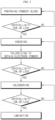
- FIG. 3 is a flow chart illustrating the manufacture of the dry electrode according to the present disclosure.
- an electrode active material, a binder resin and a conductive material are blended to prepare a powdery blend, and the crystallinity of the binder resin is determined. If the crystallinity of the binder resin is 50% or less, the powdery mixture is introduced to the next kneading step. However, if the crystallinity is higher than 50%, the powdery mixture may be further subjected to the blending step to extend the mixing time.
- binder lumps may be pulverized into primary particles and coarse fibrilization may be performed.
- the resultant powdery blend is kneaded to obtain mixture lumps, which, in turn is pulverized to obtain mixed powder for electrode. If the binder resin in the resultant mixed powder for electrode shows a crystallinity of 20% or less, the mixed powder for electrode is introduced to the next calendering step. However, if the crystallinity is higher than 20%, the mixed powder for electrode is introduced back to the kneading step.
- the resultant mixed powder for electrode is subjected to calendering to obtain a dry electrode film.
- the binder resin in the resultant dry electrode film shows a crystallinity of 10% or less
- the dry electrode film is introduced to a lamination step to obtain an electrode.
- the crystallinity is higher than 10%, the gap between the rollers, the speed ratio of the rollers or both are adjusted to control the crystallinity.
- the flow chart as shown in FIG. 3 may also be used to establish the processing conditions for satisfying the crystallinity required for each step during the manufacture of the electrode.
- Li(Ni, Co, Mn, Al)O 2 as a positive electrode active material, activated carbon and polytetrafluoroethylene (PTFE) were introduced to a blender at a weight ratio of 96:1:3, and then mixed therein at 15,000 rpm for 1 minute to prepare a powdery blend.
- a kneader was stabilized at a temperature of 150°C, the mixture was introduced to the kneader, and the kneader was operated under 1kgf/cm 2 at a rate of 25 rpm for 5 minutes to obtain mixture lumps.
- the mixture lumps were introduced to a blender and pulverized at 10,000 rpm for 30 seconds to obtain mixed powder for electrode.
- the mixed powder for electrode was introduced to a lab calender (roll diameter: 200 mm, roll temperature: 100°C, roll speed ratio: 1.5) to obtain a dry electrode film.
- the particle size of the positive electrode active material ranges about 5um to 12um.
- lithium iron phosphate (LFP) as a positive electrode active material, activated carbon and polytetrafluoroethylene (PTFE) were introduced to a blender at a weight ratio of 94:1.5:4.5, and then mixed therein at 10,000 rpm for 1 minute to prepare a powdery blend.
- a kneader was stabilized at a temperature of 150°C, the mixture was introduced to the kneader, and the kneader was operated under 1kgf/cm 2 at a rate of 50 rpm for 5 minutes to obtain mixture lumps.
- the mixture lumps were introduced to a blender and pulverized at 10,000 rpm for 20 seconds to obtain mixed powder for electrode.
- the mixed powder for electrode was introduced to a lab calender (roll diameter: 200 mm, roll temperature: 100°C, roll speed ratio: 1.75) to obtain a dry electrode film.
- the particle size of the positive electrode active material ranges about 2um to 3um.
- Li(Ni, Co, Mn, Al)O 2 as a positive electrode active material, activated carbon and polytetrafluoroethylene (PTFE) were introduced to a blender at a weight ratio of 96:1:3, and then mixed therein at 15,000 rpm for 1 minute to prepare a powdery blend.
- a kneader was stabilized at a temperature of 150°C, the mixture was introduced to the kneader, and the kneader was operated under 1kgf/cm 2 at a rate of 25 rpm for 2 minutes to obtain mixture lumps.
- the mixture lumps were introduced to a blender and pulverized at 10,000 rpm for 30 seconds to obtain mixed powder for electrode.
- the mixed powder for electrode was introduced to a lab calender (roll diameter: 200 mm, roll temperature: 100°C, roll speed ratio: 1.5) to obtain a dry electrode film.
- the particle size of the positive electrode active material ranges about 5um to 12um.
- lithium iron phosphate (LFP) as a positive electrode active material, activated carbon and polytetrafluoroethylene (PTFE) were introduced to a blender at a weight ratio of 94:1.5:4.5, and then mixed therein at 10,000 rpm for 1 minute to prepare a powdery blend.
- a kneader was stabilized at a temperature of 150°C, the mixture was introduced to the kneader, and the kneader was operated under 1kgf/cm 2 at a rate of 25 rpm for 2 minutes to obtain mixture lumps.
- the mixture lumps were introduced to a blender and pulverized at 10,000 rpm for 20 seconds to obtain mixed powder for electrode.
- the mixed powder for electrode was introduced to a lab calender (roll diameter: 200 mm, roll temperature: 100°C, roll speed ratio: 1.75) to obtain a dry electrode film.
- the particle size of the positive electrode active material ranges about 2um to 3um.
- Li(Ni, Co, Mn, Al)O 2 as a positive electrode active material, activated carbon and polytetrafluoroethylene (PTFE) were introduced to a blender at a weight ratio of 96:1:3, and then mixed therein at 400 rpm for 2 minute to prepare a powdery blend.
- a kneader was stabilized at a temperature of 150°C, the mixture was introduced to the kneader, and the kneader was operated under 1kgf/cm 2 at a rate of 25 rpm for 5 minutes to obtain mixture lumps.
- the mixture lumps were introduced to a blender and pulverized at 10,000 rpm for 30 seconds to obtain mixed powder for electrode.
- the mixed powder for electrode was introduced to a lab calender (roll diameter: 200 mm, roll temperature: 100°C, roll speed ratio: 1.5) to obtain a dry electrode film.
- the particle size of the positive electrode active material ranges about 5um to 12um.
- Li(Ni, Co, Mn, Al)O 2 as a positive electrode active material, activated carbon and polytetrafluoroethylene (PTFE) were introduced to a blender at a weight ratio of 96:1:3, and then mixed therein at 15,000 rpm for 1 minute and put the resultant into a super mixer and mixed therein at 800rpm for 30 sec to prepare a powdery blend.
- the temperature was controlled under 23 °C and the pressure was controlled under 85 psi.
- the powdery blend was introduced to a lab calender (roll diameter: 200 mm, roll temperature: 100°C, roll speed ratio: 1.5) to obtain a dry electrode film.
- the particle size of the positive electrode active material ranges about 5um to 12um.
- Binder content (wt%) Shear rate (sec -1 , in kneading stpe) Tm (°C) ⁇ Hm (J/g) ⁇ Hm expressed based on 100% of binder (J/g) Crystallinity (%) ⁇ Hm/ ⁇ Hm°
- Tensile strength MD, Mpa
- Tensile elongation %)
- Binder 1 100 348.3 72.399 72.399 84.78
- Powdery blend 3 347.1 1.138 37.933 44.42 Mixed powder for electrode 3 48 - - - 0 Dry electrode film 3 - - - 0 1.87 5.8
- Shear rate sec -1 , in kneading stpe
- Binder 2 100 347.3 72.974 72.974 85.45 Powdery blend 4.5 346.58 1.776 39.458 46.20 Mixed powder for electrode 4.5 240 346.94 0.205 4.561 5.34 Dry electrode film 4.5 347.11 0.109 2.431 2.85 0.70 2.1 Ex.
- Binder 1 100 348.3 72.399 72.399 84.78 Powdery blend 3 347.1 1.138 37.933 44.42 Mixed powder for electrode 3 48 348.3 0.3505 11.683 13.68 Dry electrode film 3 - - - 0 0.98 4.6
- Ingredients Binder content (wt%) Shear rate (sec -1 , in kneading stpe) Tm (°C) ⁇ Hm (J/g) ⁇ Hm expressed based on 100% of binder (J/g) Crystallinity (%) ⁇ Hm/ ⁇ Hm°
- Tensile strength MD, Mpa
- Tensile elongation %) Compar tive Ex.
- Binder 1 100 347.3 72.974 72.974 85.45 Powdery blend 4.5 346.58 1.776 39.458 46.20 Mixed powder for electrode 4.5 48sec-1 345.06 0.874 19.416 22.74 Dry electrode film 4.5 - 0 Cannot be formed into film 0 Compar tive Ex. 2
- Binder 2 100 348.3 72.399 72.399 84.78 Powdery blend 3 347.0 1.6625 55.417 64.89 Mixed powder for electrode 3 48sec-1 346.8 0.6866 22.887 26.49 Dry electrode film 3 - - - - 0 Cannot be formed into film 0 Compar tive Ex. 3
- Binder 1 100 348.3 72.399 72.399 84.78 Powdery blend 3 347.1 1.2 39.96 32.53 Mixed powder for electrode Dry electrode film 3 - - - - 0 Cannot be formed into film 0
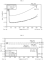
- FIG. 1 is a graph illustrating the thermogravimetric analysis result using differential scanning calorimetry (DSC) according to Example 1. It can be seen from FIG. 1 that each of the subsequently processed mixed powder for electrode (Grinding) and dry electrode film (Sheet) shows a lower crystallinity as compared to the powdery blend (Mixing).
- FIG. 2 is a graph illustrating the thermogravimetric analysis result using differential scanning calorimetry (DSC) according to Example 2.
- each of the subsequently processed mixed powder for electrode (Grinding) and dry electrode film (Sheet) shows a lower crystallinity as compared to the powdery blend (Mixing).
- each of the dry electrode films according to Examples shows a tensile strength of 0.5 MPa or higher and a tensile elongation of 2% or more.
- PTFE in FIG. 2 represents the specific crystallinity of 100% PTFE determined before processing PTFE, and is provided for the purpose of comparison with the crystallinity of PTFE after processing.
- Comparative Examples 1 and 2 the crystallinity of the binder resin of the obtained electrode mixture powder exceeded 20%. This means that fiberization was insufficient in the obtained mixed powder for electrodes, and it was difficult to manufacture a sheet-like dry electrode film through a subsequent calendering process.
- the degree of crystallinity of the binder resin in the powdery blend exceeded 60%, so that sufficient fiberization was not achieved even if the subsequent process was performed.
- the kneading process according to the present invention was not applied, so fine fiberization was not sufficiently achieved.
- Example and Comparative examples a sample was taken from each of the powdery blend, mixed powder for electrode and the dry electrode film to measure each crystallinity. Next, about 5-12 mg of each sample was weighed and introduced to a differential scanning calorimeter (DSC, TA company), and then the melting point (Tm) and heat of melting ( ⁇ Hm) were measured in a temperature range of 25-360°C at a heating rate of 10°C/min under nitrogen atmosphere.
- DSC differential scanning calorimeter
- the melting point (Tm) and the melting enthalpy ( ⁇ Hm) were analyzed based on the temperature (peak temperature) at the time point of showing the highest enthalpy during melting using the TROIS program of TA.
- the degree of crystallinity of each sample is expressed in % by dividing the measured enthalpy of melting ( ⁇ Hm) by DSC by the value of enthalpy of melting ( ⁇ Hm0) of a theoretically perfect crystal (100% crystallinity), which was calculated according to Mathematical Formula 1 as presented above.
- the heat of melting ( ⁇ Hf 0 ) of 100% binder crystals was taken as 85.4 J/g ( Polymer, vol. 46, 2005, pp8872-8882 ).
- the dry electrode film obtained from each Example and Comparative example was cut into a width of 10 mm. Then, the tensile strength and tensile elongation were measured at a tensile rate of 5 mm/min three times by using a tensile strength tester. The results are shown as the average value of the three measurements.
- Tensile strength is a applied stress until fracture occurs, and tensile elongation indicates the percentage (%, ratio of change in length to original length) of the elongated specimen until fracture occurs.
Landscapes
- Chemical & Material Sciences (AREA)
- Engineering & Computer Science (AREA)
- Chemical Kinetics & Catalysis (AREA)
- Electrochemistry (AREA)
- General Chemical & Material Sciences (AREA)
- Manufacturing & Machinery (AREA)
- Materials Engineering (AREA)
- Power Engineering (AREA)
- Dispersion Chemistry (AREA)
- Microelectronics & Electronic Packaging (AREA)
- Battery Electrode And Active Subsutance (AREA)
Claims (15)
- Elektrode für eine elektrochemische Vorrichtung, umfassend einen Elektrodentrockenfilm, der durch ein Trockenherstellungsverfahren ohne Verwendung eines Lösungsmittels erhalten wird, wobei der Elektrodentrockenfilm ein Elektrodenaktivmaterial, ein leitfähiges Material und ein Bindemittelharz umfasst, wobei das Bindemittelharz in dem Elektrodentrockenfilm eine Kristallinität von 10 % oder weniger, bestimmt wie in der Beschreibung beschrieben, aufweist.
- Elektrode für eine elektrochemische Vorrichtung gemäß Anspruch 1, wobei der Elektrodentrockenfilm eine Zugfestigkeit von 0,5 MPa oder mehr in Maschinenrichtung, bestimmt wie in der Beschreibung beschrieben, aufweist.
- Elektrode für eine elektrochemische Vorrichtung gemäß Anspruch 1, wobei der Elektrodentrockenfilm eine Zugdehnung von 2 % oder mehr, bestimmt wie in der Beschreibung beschrieben, aufweist.
- Elektrode für eine elektrochemische Vorrichtung gemäß Anspruch 1, wobei der Elektrodenfilm eine Porosität von 20-50 Vol.-%, bestimmt wie in der Beschreibung beschrieben, aufweist.
- Verfahren zur Herstellung der Elektrode für eine elektrochemische Vorrichtung wie in Anspruch 1 definiert, wobei das Verfahren die Schritte umfasst:(a) Herstellen einer pulverförmigen Mischung, umfassend ein Elektrodenaktivmaterial, ein leitfähiges Material und ein Bindemittelharz,(b) Kneten der pulverförmige Mischung bei 70-200°C, um Mischungsklumpen herzustellen,(c) Pulverisieren der Mischungsklumpen, um ein Mischpulver für eine Elektrode zu erhalten, und(d) Kalandrieren des Mischpulvers für eine Elektrode, um einen freistehenden Elektrodentrockenfilm zu erhalten, wobei das Bindemittelharz, das in dem aus Schritt (d) erhaltenen Elektrodentrockenfilm enthalten ist, eine Kristallinität (d) von 10 % oder weniger, bestimmt wie in der Beschreibung beschrieben, aufweist.
- Verfahren zur Herstellung der Elektrode für eine elektrochemische Vorrichtung gemäß Anspruch 5, wobei das Bindemittelharz, das in dem aus Schritt (c) erhaltenen Mischpulver für eine Elektrode enthalten ist, eine Kristallinität (c) von 20 % oder weniger, bestimmt wie in der Beschreibung beschrieben, aufweist.
- Verfahren zur Herstellung der Elektrode für eine elektrochemische Vorrichtung gemäß Anspruch 5, wobei das Bindemittelharz, das in der aus Schritt (a) erhaltenen Mischung enthalten ist, eine Kristallinität (a) von 50 % oder weniger, bestimmt wie in der Beschreibung beschrieben, aufweist.
- Verfahren zur Herstellung der Elektrode für eine elektrochemische Vorrichtung gemäß Anspruch 5, wobei Schritt (a) bei 500-30.000 U/min durchgeführt wird.
- Verfahren zur Herstellung der Elektrode für eine elektrochemische Vorrichtung gemäß Anspruch 5, wobei Schritt (b) unter einer Rotationsgeschwindigkeit von 100 U/min oder weniger durchgeführt wird.
- Verfahren zur Herstellung der Elektrode für eine elektrochemische Vorrichtung gemäß Anspruch 9, wobei Schritt (b) unter einem Druck von 0,5 kgf/cm2 bis 10 kgf/cm2 durchgeführt wird.
- Verfahren zur Herstellung der Elektrode für eine elektrochemische Vorrichtung gemäß Anspruch 10, wobei Schritt (b) unter einem Druck von Atmosphärendruck oder mehr durchgeführt wird.
- Elektrode für eine elektrochemische Vorrichtung gemäß Anspruch 1, wobei das Bindemittelharz Polytetrafluorethylen (PTFE), Polyvinylidenfluorid (PVDF), Polyolefin oder eine Mischung aus zwei oder mehr von diesen umfasst.
- Elektrode für eine elektrochemische Vorrichtung gemäß Anspruch 1, die ferner einen Stromkollektor umfasst, wobei der Elektrodentrockenfilm auf mindestens einer Oberfläche oder beiden Oberflächen des Stromkollektors angeordnet ist.
- Verfahren zur Herstellung der Elektrode für eine elektrochemische Vorrichtung gemäß Anspruch 5, das ferner einen Schritt zur Herstellung eines Stromkollektors umfasst, der den Elektrodentrockenfilm auf mindestens einer Oberfläche des Stromkollektors anordnet und eine Laminierung durchführt.
- Sekundärbatterie, umfassend die Trockenelektrode wie in Anspruch 1 definiert, wobei die Trockenelektrode eine positive Elektrode ist und eine Elektrodenanordnung, die die positive Elektrode, eine negative Elektrode und einen Separator umfasst, zusammen mit einem lithiumhaltigen nichtwässrigen Elektrolyten in einem Batteriegehäuse aufgenommen ist.
Priority Applications (1)
| Application Number | Priority Date | Filing Date | Title |
|---|---|---|---|
| EP24204208.3A EP4475233A1 (de) | 2021-08-06 | 2022-08-05 | Elektrode für elektrochemische vorrichtung mit trockenelektrodenfilm und herstellungsverfahren dafür |
Applications Claiming Priority (2)
| Application Number | Priority Date | Filing Date | Title |
|---|---|---|---|
| KR20210104169 | 2021-08-06 | ||
| KR1020220097481A KR102661426B1 (ko) | 2021-08-06 | 2022-08-04 | 건식 전극 필름을 포함하는 전기화학소자용 전극 및 이의 제조 방법 |
Related Child Applications (2)
| Application Number | Title | Priority Date | Filing Date |
|---|---|---|---|
| EP24204208.3A Division EP4475233A1 (de) | 2021-08-06 | 2022-08-05 | Elektrode für elektrochemische vorrichtung mit trockenelektrodenfilm und herstellungsverfahren dafür |
| EP24204208.3A Division-Into EP4475233A1 (de) | 2021-08-06 | 2022-08-05 | Elektrode für elektrochemische vorrichtung mit trockenelektrodenfilm und herstellungsverfahren dafür |
Publications (2)
| Publication Number | Publication Date |
|---|---|
| EP4152445A1 EP4152445A1 (de) | 2023-03-22 |
| EP4152445B1 true EP4152445B1 (de) | 2025-01-01 |
Family
ID=82846459
Family Applications (2)
| Application Number | Title | Priority Date | Filing Date |
|---|---|---|---|
| EP24204208.3A Pending EP4475233A1 (de) | 2021-08-06 | 2022-08-05 | Elektrode für elektrochemische vorrichtung mit trockenelektrodenfilm und herstellungsverfahren dafür |
| EP22189055.1A Active EP4152445B1 (de) | 2021-08-06 | 2022-08-05 | Elektrode für elektrochemische vorrichtung, die eine trockenelektrodenfolie umfasst, und herstellungsverfahren zdafür |
Family Applications Before (1)
| Application Number | Title | Priority Date | Filing Date |
|---|---|---|---|
| EP24204208.3A Pending EP4475233A1 (de) | 2021-08-06 | 2022-08-05 | Elektrode für elektrochemische vorrichtung mit trockenelektrodenfilm und herstellungsverfahren dafür |
Country Status (5)
| Country | Link |
|---|---|
| US (3) | US12002962B2 (de) |
| EP (2) | EP4475233A1 (de) |
| ES (1) | ES3012117T3 (de) |
| HU (1) | HUE069856T2 (de) |
| PL (1) | PL4152445T3 (de) |
Families Citing this family (11)
| Publication number | Priority date | Publication date | Assignee | Title |
|---|---|---|---|---|
| JP2022505069A (ja) | 2018-11-06 | 2022-01-14 | クアンタムスケープ バッテリー,インコーポレイテッド | カソライト添加剤及びリチウム充填ガーネットセパレーターを有する電気化学セル |
| HUE069856T2 (hu) * | 2021-08-06 | 2025-04-28 | Lg Energy Solution Ltd | Száraz elektródafilmet tartalmazó elektróda elektrokémiai eszközhöz, és eljárás annak elõállítására |
| WO2023121838A1 (en) | 2021-11-30 | 2023-06-29 | Quantumscape Battery, Inc. | Catholytes for a solid-state battery |
| MX2024006697A (es) | 2021-12-17 | 2024-06-19 | Quantumscape Battery Inc | Materiales catodicos con especies superficiales de oxido. |
| US20240322113A1 (en) * | 2023-03-26 | 2024-09-26 | Samsung Sdi Co., Ltd. | Method of preparing dry electrode film, dry electrode, and lithium battery |
| WO2025011825A1 (de) | 2023-07-10 | 2025-01-16 | Troester Gmbh & Co. Kg | Verfahren zur herstellung eines lösungsmittelfreien elektrodencompounds sowie ein verfahren zum ausbringen einer vorlage mittels einer austragsvorrichtung |
| KR20250033433A (ko) | 2023-08-29 | 2025-03-10 | 삼성에스디아이 주식회사 | 건식 파우더 니딩 장치 |
| CN119725392B (zh) * | 2023-09-27 | 2025-10-14 | 远景睿泰动力技术(上海)有限公司 | 一种干法电极及其制备方法和二次电池 |
| US12431505B2 (en) * | 2023-11-27 | 2025-09-30 | Atlas Power Technologies Inc. | Dry electrode for energy storing devices |
| WO2025111691A1 (en) * | 2023-11-27 | 2025-06-05 | Atlas Power Technologies Inc. | Selected particle size dry electrode for storage devices |
| US12272813B1 (en) | 2024-01-15 | 2025-04-08 | Atlas Power Technologies Inc. | Selected particle size dry electrode for storage devices |
Citations (13)
| Publication number | Priority date | Publication date | Assignee | Title |
|---|---|---|---|---|
| EP0126511B1 (de) | 1983-05-19 | 1988-08-24 | Electrochemische Energieconversie N.V. | Poröse Elektrode |
| US6127474A (en) | 1997-08-27 | 2000-10-03 | Andelman; Marc D. | Strengthened conductive polymer stabilized electrode composition and method of preparing |
| US6335857B1 (en) | 1998-07-27 | 2002-01-01 | Asahi Glass Company Ltd. | Electric double layer capacitor and electrode therefor |
| JP2004186267A (ja) | 2002-11-29 | 2004-07-02 | Honda Motor Co Ltd | 電気二重層コンデンサの電極形成用顆粒、その製造方法、電極シート、分極性電極および分極性電極を用いた電気二重層コンデンサ |
| US7508651B2 (en) | 2003-07-09 | 2009-03-24 | Maxwell Technologies, Inc. | Dry particle based adhesive and dry film and methods of making same |
| US20160340476A1 (en) | 2014-02-19 | 2016-11-24 | Hutchinson | Process for preparing an electrode composition or composition with magnetic properties, mixture and composition obtained by means of said process and said electrode |
| WO2017151518A1 (en) | 2016-03-01 | 2017-09-08 | Maxwell Technologies, Inc. | Electrode for an energy storage device and method for fabricating a dry energy storage device electrode film |
| EP3309879A1 (de) | 2015-06-12 | 2018-04-18 | LG Chem, Ltd. | Positivelektrodenmischung und sekundärbatterie damit |
| US20180175366A1 (en) | 2015-06-26 | 2018-06-21 | Florida State University Research Foundation, Inc. | Dry process method for producing electrodes for electrochemical devices and electrodes for electrochemical devices |
| EP1644136B1 (de) | 2003-07-09 | 2018-08-29 | Maxwell Technologies, Inc. | Auf trockene teilchen basierende elektro-mechanische vorrichtung und herstellungsverfahren dafür |
| EP3696887A1 (de) | 2017-10-10 | 2020-08-19 | Nissan Motor Co., Ltd. | Elektrode einer sekundärbatterie mit wasserfreiem elektrolyt |
| CN111916678A (zh) | 2020-09-15 | 2020-11-10 | 天目湖先进储能技术研究院有限公司 | 一种高比能锂电池电极及其干法制备方法和锂电池 |
| WO2021028619A1 (en) | 2019-08-13 | 2021-02-18 | Broadbit Batteries Oy | An electrode material and components therefrom for use in an electrochemical device and processes for the manufacture thereof |
Family Cites Families (15)
| Publication number | Priority date | Publication date | Assignee | Title |
|---|---|---|---|---|
| US20040224229A1 (en) * | 2003-05-09 | 2004-11-11 | Mansuetto Michael F. | Alkaline cell with copper oxide cathode |
| US20070122698A1 (en) * | 2004-04-02 | 2007-05-31 | Maxwell Technologies, Inc. | Dry-particle based adhesive and dry film and methods of making same |
| DE102012203019A1 (de) | 2012-02-28 | 2013-08-29 | Technische Universität Dresden | Kathode für Lithium-haltige Batterien und lösungsmittelfreies Verfahren zu deren Herstellung |
| HUE051927T2 (hu) | 2014-03-10 | 2021-04-28 | Maxwell Lab | Eljárás és berendezések polimerfibrillálásra elektromos térben |
| CN106463730B (zh) | 2014-04-02 | 2020-04-07 | 日本瑞翁株式会社 | 二次电池用正极、二次电池用正极的制造方法及二次电池 |
| MX2016013413A (es) | 2014-04-18 | 2017-04-06 | Maxwell Lab | Electrodo de dispositivo para almacenamiento de energia en seco y metodos para elaborar el mismo. |
| CN107112500B (zh) | 2014-10-02 | 2020-05-19 | 株式会社Lg 化学 | 包括橡胶类粘合剂的正极活性材料浆料及由其制备的正极 |
| JP2016186921A (ja) | 2015-03-27 | 2016-10-27 | オートモーティブエナジーサプライ株式会社 | リチウムイオン二次電池 |
| ES2939980T3 (es) | 2016-11-21 | 2023-04-28 | Lg Energy Solution Ltd | Electrodo para dispositivo electroquímico y método para fabricar el mismo |
| KR102261501B1 (ko) | 2017-09-29 | 2021-06-07 | 주식회사 엘지에너지솔루션 | 전극 합제의 제조 방법 및 전극 합제 |
| US11545666B2 (en) | 2018-03-30 | 2023-01-03 | Tesla, Inc. | Compositions and methods for dry electrode films including microparticulate non-fibrillizable binders |
| EP3794657A1 (de) | 2018-05-14 | 2021-03-24 | Maxwell Technologies, Inc. | Zusammensetzungen und verfahren für trockene elektrodenschichten mit reduziertem bindemittelgehalt |
| JP6721636B2 (ja) | 2018-07-24 | 2020-07-15 | 株式会社エンビジョンAescジャパン | 電気デバイス用電極とその製造方法、並びに該電極を用いてなる電気デバイス |
| JP7672976B2 (ja) | 2018-11-08 | 2025-05-08 | テスラ・インコーポレーテッド | 塩及び/又は発泡体を含むエネルギー貯蔵装置用の組成物及び方法 |
| HUE069856T2 (hu) * | 2021-08-06 | 2025-04-28 | Lg Energy Solution Ltd | Száraz elektródafilmet tartalmazó elektróda elektrokémiai eszközhöz, és eljárás annak elõállítására |
-
2022
- 2022-08-05 HU HUE22189055A patent/HUE069856T2/hu unknown
- 2022-08-05 EP EP24204208.3A patent/EP4475233A1/de active Pending
- 2022-08-05 ES ES22189055T patent/ES3012117T3/es active Active
- 2022-08-05 EP EP22189055.1A patent/EP4152445B1/de active Active
- 2022-08-05 PL PL22189055.1T patent/PL4152445T3/pl unknown
- 2022-08-05 US US17/881,879 patent/US12002962B2/en active Active
-
2024
- 2024-04-25 US US18/646,276 patent/US20240274823A1/en active Pending
-
2025
- 2025-01-30 US US19/041,040 patent/US20250192183A1/en active Pending
Patent Citations (13)
| Publication number | Priority date | Publication date | Assignee | Title |
|---|---|---|---|---|
| EP0126511B1 (de) | 1983-05-19 | 1988-08-24 | Electrochemische Energieconversie N.V. | Poröse Elektrode |
| US6127474A (en) | 1997-08-27 | 2000-10-03 | Andelman; Marc D. | Strengthened conductive polymer stabilized electrode composition and method of preparing |
| US6335857B1 (en) | 1998-07-27 | 2002-01-01 | Asahi Glass Company Ltd. | Electric double layer capacitor and electrode therefor |
| JP2004186267A (ja) | 2002-11-29 | 2004-07-02 | Honda Motor Co Ltd | 電気二重層コンデンサの電極形成用顆粒、その製造方法、電極シート、分極性電極および分極性電極を用いた電気二重層コンデンサ |
| EP1644136B1 (de) | 2003-07-09 | 2018-08-29 | Maxwell Technologies, Inc. | Auf trockene teilchen basierende elektro-mechanische vorrichtung und herstellungsverfahren dafür |
| US7508651B2 (en) | 2003-07-09 | 2009-03-24 | Maxwell Technologies, Inc. | Dry particle based adhesive and dry film and methods of making same |
| US20160340476A1 (en) | 2014-02-19 | 2016-11-24 | Hutchinson | Process for preparing an electrode composition or composition with magnetic properties, mixture and composition obtained by means of said process and said electrode |
| EP3309879A1 (de) | 2015-06-12 | 2018-04-18 | LG Chem, Ltd. | Positivelektrodenmischung und sekundärbatterie damit |
| US20180175366A1 (en) | 2015-06-26 | 2018-06-21 | Florida State University Research Foundation, Inc. | Dry process method for producing electrodes for electrochemical devices and electrodes for electrochemical devices |
| WO2017151518A1 (en) | 2016-03-01 | 2017-09-08 | Maxwell Technologies, Inc. | Electrode for an energy storage device and method for fabricating a dry energy storage device electrode film |
| EP3696887A1 (de) | 2017-10-10 | 2020-08-19 | Nissan Motor Co., Ltd. | Elektrode einer sekundärbatterie mit wasserfreiem elektrolyt |
| WO2021028619A1 (en) | 2019-08-13 | 2021-02-18 | Broadbit Batteries Oy | An electrode material and components therefrom for use in an electrochemical device and processes for the manufacture thereof |
| CN111916678A (zh) | 2020-09-15 | 2020-11-10 | 天目湖先进储能技术研究院有限公司 | 一种高比能锂电池电极及其干法制备方法和锂电池 |
Non-Patent Citations (9)
| Title |
|---|
| "Polymers - A property database, 2nd ed.", 1 January 2009, CRC PRESS , ISBN: 978-0-8493-3940-0, article ANONYMOUS: "S28 - Styrene-butadiene rubber", pages: 1051 - 1054, XP009563546 |
| "Technische Elastomerwerkstoffe : Basis für Hightech-Lösungen in der Dichtungs- und Schwingungstechnik", vol. 293, 31 December 2006, VERLAG MODERNE INDUSTRIE , ISBN: 978-3-937889-42-9, article MEIKE RINNBAUER: "Technische Elastomerwerkstoffe", pages: 1 - 70, XP055556927 |
| D18 - YEC product catalogue 2009 (Type List for Electric Double Layer Capacitors) |
| D19 - YEC packing list to customer 2018 |
| D20 - Maxwell packing list 2014 |
| D21 - Maxwell invoice 2018 |
| D22 - Maxwell certificate of compliance 2018 |
| D23 - YEC invoice 2019 |
| D24 - Laboratory report 2025 |
Also Published As
| Publication number | Publication date |
|---|---|
| ES3012117T3 (en) | 2025-04-08 |
| US20250192183A1 (en) | 2025-06-12 |
| US20230042207A1 (en) | 2023-02-09 |
| HUE069856T2 (hu) | 2025-04-28 |
| EP4475233A1 (de) | 2024-12-11 |
| US12002962B2 (en) | 2024-06-04 |
| US20240274823A1 (en) | 2024-08-15 |
| EP4152445A1 (de) | 2023-03-22 |
| KR20240054956A (ko) | 2024-04-26 |
| PL4152445T3 (pl) | 2025-03-17 |
Similar Documents
| Publication | Publication Date | Title |
|---|---|---|
| EP4152445B1 (de) | Elektrode für elektrochemische vorrichtung, die eine trockenelektrodenfolie umfasst, und herstellungsverfahren zdafür | |
| EP4216298A1 (de) | Elektrodenpulver für trockenelektrode und verfahren und vorrichtung | |
| EP4318650A1 (de) | Herstellungssystem und verfahren für trockene elektrodenfolie | |
| CA3227840A1 (en) | Electrode for electrochemical device comprising dry electrode film and method for manufacturing same | |
| US20250167225A1 (en) | Mixture Powder for Dry Electrode and Dry Electrode for Electrochemical Device Comprising the Same | |
| KR20230025359A (ko) | 건식 전극 필름을 포함하는 전기화학소자용 전극 및 이의 제조 방법 | |
| KR102838158B1 (ko) | 전극용 필름, 이를 포함하는 전극, 이차전지, 및 이의 제조 방법 | |
| EP4465407A1 (de) | Elektrodenanordnung und sekundärbatterie damit | |
| US20250239614A1 (en) | Electrode, Secondary Battery Comprising the Same, and Method for Manufacturing the Same | |
| KR102918103B1 (ko) | 건식 전극 필름을 포함하는 전기화학소자용 전극 및 이의 제조 방법 | |
| KR20260015973A (ko) | 건식 전극 필름을 포함하는 전기화학소자용 전극 및 이의 제조 방법 | |
| CN117916905A (zh) | 电极、包括该电极的二次电池以及制造该电极的方法 | |
| EP4571871A1 (de) | Elektrodenmischungsfilm, verfahren zur herstellung davon, trockene elektrode und lithiumsekundärbatterie damit |
Legal Events
| Date | Code | Title | Description |
|---|---|---|---|
| PUAI | Public reference made under article 153(3) epc to a published international application that has entered the european phase |
Free format text: ORIGINAL CODE: 0009012 |
|
| STAA | Information on the status of an ep patent application or granted ep patent |
Free format text: STATUS: REQUEST FOR EXAMINATION WAS MADE |
|
| 17P | Request for examination filed |
Effective date: 20220805 |
|
| AK | Designated contracting states |
Kind code of ref document: A1 Designated state(s): AL AT BE BG CH CY CZ DE DK EE ES FI FR GB GR HR HU IE IS IT LI LT LU LV MC MK MT NL NO PL PT RO RS SE SI SK SM TR |
|
| GRAP | Despatch of communication of intention to grant a patent |
Free format text: ORIGINAL CODE: EPIDOSNIGR1 |
|
| STAA | Information on the status of an ep patent application or granted ep patent |
Free format text: STATUS: GRANT OF PATENT IS INTENDED |
|
| INTG | Intention to grant announced |
Effective date: 20240611 |
|
| GRAJ | Information related to disapproval of communication of intention to grant by the applicant or resumption of examination proceedings by the epo deleted |
Free format text: ORIGINAL CODE: EPIDOSDIGR1 |
|
| STAA | Information on the status of an ep patent application or granted ep patent |
Free format text: STATUS: REQUEST FOR EXAMINATION WAS MADE |
|
| GRAP | Despatch of communication of intention to grant a patent |
Free format text: ORIGINAL CODE: EPIDOSNIGR1 |
|
| STAA | Information on the status of an ep patent application or granted ep patent |
Free format text: STATUS: GRANT OF PATENT IS INTENDED |
|
| P01 | Opt-out of the competence of the unified patent court (upc) registered |
Free format text: CASE NUMBER: APP_50639/2024 Effective date: 20240906 |
|
| INTG | Intention to grant announced |
Effective date: 20241008 |
|
| GRAS | Grant fee paid |
Free format text: ORIGINAL CODE: EPIDOSNIGR3 |
|
| GRAA | (expected) grant |
Free format text: ORIGINAL CODE: 0009210 |
|
| STAA | Information on the status of an ep patent application or granted ep patent |
Free format text: STATUS: THE PATENT HAS BEEN GRANTED |
|
| AK | Designated contracting states |
Kind code of ref document: B1 Designated state(s): AL AT BE BG CH CY CZ DE DK EE ES FI FR GB GR HR HU IE IS IT LI LT LU LV MC MK MT NL NO PL PT RO RS SE SI SK SM TR |
|
| REG | Reference to a national code |
Ref country code: GB Ref legal event code: FG4D |
|
| REG | Reference to a national code |
Ref country code: CH Ref legal event code: EP |
|
| REG | Reference to a national code |
Ref country code: DE Ref legal event code: R096 Ref document number: 602022009266 Country of ref document: DE |
|
| REG | Reference to a national code |
Ref country code: IE Ref legal event code: FG4D |
|
| REG | Reference to a national code |
Ref country code: NL Ref legal event code: FP |
|
| REG | Reference to a national code |
Ref country code: SE Ref legal event code: TRGR |
|
| REG | Reference to a national code |
Ref country code: ES Ref legal event code: FG2A Ref document number: 3012117 Country of ref document: ES Kind code of ref document: T3 Effective date: 20250408 |
|
| REG | Reference to a national code |
Ref country code: LT Ref legal event code: MG9D |
|
| REG | Reference to a national code |
Ref country code: HU Ref legal event code: AG4A Ref document number: E069856 Country of ref document: HU |
|
| REG | Reference to a national code |
Ref country code: AT Ref legal event code: MK05 Ref document number: 1757236 Country of ref document: AT Kind code of ref document: T Effective date: 20250101 |
|
| PG25 | Lapsed in a contracting state [announced via postgrant information from national office to epo] |
Ref country code: FI Free format text: LAPSE BECAUSE OF FAILURE TO SUBMIT A TRANSLATION OF THE DESCRIPTION OR TO PAY THE FEE WITHIN THE PRESCRIBED TIME-LIMIT Effective date: 20250101 |
|
| PG25 | Lapsed in a contracting state [announced via postgrant information from national office to epo] |
Ref country code: IS Free format text: LAPSE BECAUSE OF FAILURE TO SUBMIT A TRANSLATION OF THE DESCRIPTION OR TO PAY THE FEE WITHIN THE PRESCRIBED TIME-LIMIT Effective date: 20250501 Ref country code: NO Free format text: LAPSE BECAUSE OF FAILURE TO SUBMIT A TRANSLATION OF THE DESCRIPTION OR TO PAY THE FEE WITHIN THE PRESCRIBED TIME-LIMIT Effective date: 20250401 |
|
| PGFP | Annual fee paid to national office [announced via postgrant information from national office to epo] |
Ref country code: BE Payment date: 20250424 Year of fee payment: 4 |
|
| PG25 | Lapsed in a contracting state [announced via postgrant information from national office to epo] |
Ref country code: HR Free format text: LAPSE BECAUSE OF FAILURE TO SUBMIT A TRANSLATION OF THE DESCRIPTION OR TO PAY THE FEE WITHIN THE PRESCRIBED TIME-LIMIT Effective date: 20250101 |
|
| PG25 | Lapsed in a contracting state [announced via postgrant information from national office to epo] |
Ref country code: PT Free format text: LAPSE BECAUSE OF FAILURE TO SUBMIT A TRANSLATION OF THE DESCRIPTION OR TO PAY THE FEE WITHIN THE PRESCRIBED TIME-LIMIT Effective date: 20250502 Ref country code: LV Free format text: LAPSE BECAUSE OF FAILURE TO SUBMIT A TRANSLATION OF THE DESCRIPTION OR TO PAY THE FEE WITHIN THE PRESCRIBED TIME-LIMIT Effective date: 20250101 |
|
| PG25 | Lapsed in a contracting state [announced via postgrant information from national office to epo] |
Ref country code: BG Free format text: LAPSE BECAUSE OF FAILURE TO SUBMIT A TRANSLATION OF THE DESCRIPTION OR TO PAY THE FEE WITHIN THE PRESCRIBED TIME-LIMIT Effective date: 20250101 Ref country code: GR Free format text: LAPSE BECAUSE OF FAILURE TO SUBMIT A TRANSLATION OF THE DESCRIPTION OR TO PAY THE FEE WITHIN THE PRESCRIBED TIME-LIMIT Effective date: 20250402 |
|
| PG25 | Lapsed in a contracting state [announced via postgrant information from national office to epo] |
Ref country code: AT Free format text: LAPSE BECAUSE OF FAILURE TO SUBMIT A TRANSLATION OF THE DESCRIPTION OR TO PAY THE FEE WITHIN THE PRESCRIBED TIME-LIMIT Effective date: 20250101 |
|
| PG25 | Lapsed in a contracting state [announced via postgrant information from national office to epo] |
Ref country code: CZ Free format text: LAPSE BECAUSE OF FAILURE TO SUBMIT A TRANSLATION OF THE DESCRIPTION OR TO PAY THE FEE WITHIN THE PRESCRIBED TIME-LIMIT Effective date: 20250101 |
|
| PGFP | Annual fee paid to national office [announced via postgrant information from national office to epo] |
Ref country code: NL Payment date: 20250722 Year of fee payment: 4 |
|
| PGFP | Annual fee paid to national office [announced via postgrant information from national office to epo] |
Ref country code: HU Payment date: 20250827 Year of fee payment: 4 |
|
| REG | Reference to a national code |
Ref country code: DE Ref legal event code: R026 Ref document number: 602022009266 Country of ref document: DE |
|
| PLBI | Opposition filed |
Free format text: ORIGINAL CODE: 0009260 |
|
| PG25 | Lapsed in a contracting state [announced via postgrant information from national office to epo] |
Ref country code: SM Free format text: LAPSE BECAUSE OF FAILURE TO SUBMIT A TRANSLATION OF THE DESCRIPTION OR TO PAY THE FEE WITHIN THE PRESCRIBED TIME-LIMIT Effective date: 20250101 |
|
| PGFP | Annual fee paid to national office [announced via postgrant information from national office to epo] |
Ref country code: ES Payment date: 20250911 Year of fee payment: 4 |
|
| PG25 | Lapsed in a contracting state [announced via postgrant information from national office to epo] |
Ref country code: DK Free format text: LAPSE BECAUSE OF FAILURE TO SUBMIT A TRANSLATION OF THE DESCRIPTION OR TO PAY THE FEE WITHIN THE PRESCRIBED TIME-LIMIT Effective date: 20250101 |
|
| PGFP | Annual fee paid to national office [announced via postgrant information from national office to epo] |
Ref country code: DE Payment date: 20250721 Year of fee payment: 4 |
|
| PGFP | Annual fee paid to national office [announced via postgrant information from national office to epo] |
Ref country code: IT Payment date: 20250901 Year of fee payment: 4 Ref country code: TR Payment date: 20250723 Year of fee payment: 4 Ref country code: PL Payment date: 20250728 Year of fee payment: 4 |
|
| PLAX | Notice of opposition and request to file observation + time limit sent |
Free format text: ORIGINAL CODE: EPIDOSNOBS2 |
|
| PGFP | Annual fee paid to national office [announced via postgrant information from national office to epo] |
Ref country code: FR Payment date: 20250725 Year of fee payment: 4 |
|
| PGFP | Annual fee paid to national office [announced via postgrant information from national office to epo] |
Ref country code: SE Payment date: 20250722 Year of fee payment: 4 |
|
| PG25 | Lapsed in a contracting state [announced via postgrant information from national office to epo] |
Ref country code: EE Free format text: LAPSE BECAUSE OF FAILURE TO SUBMIT A TRANSLATION OF THE DESCRIPTION OR TO PAY THE FEE WITHIN THE PRESCRIBED TIME-LIMIT Effective date: 20250101 |
|
| PG25 | Lapsed in a contracting state [announced via postgrant information from national office to epo] |
Ref country code: RO Free format text: LAPSE BECAUSE OF FAILURE TO SUBMIT A TRANSLATION OF THE DESCRIPTION OR TO PAY THE FEE WITHIN THE PRESCRIBED TIME-LIMIT Effective date: 20250101 |
|
| PG25 | Lapsed in a contracting state [announced via postgrant information from national office to epo] |
Ref country code: SK Free format text: LAPSE BECAUSE OF FAILURE TO SUBMIT A TRANSLATION OF THE DESCRIPTION OR TO PAY THE FEE WITHIN THE PRESCRIBED TIME-LIMIT Effective date: 20250101 |
|
| 26 | Opposition filed |
Opponent name: CELLFORCE GROUP GMBH Effective date: 20250930 |