EP4151982A1 - Vorrichtung zur inspektion von ermüdungsbrüchen eines gehäuseschweissteils eines batteriemoduls - Google Patents
Vorrichtung zur inspektion von ermüdungsbrüchen eines gehäuseschweissteils eines batteriemoduls Download PDFInfo
- Publication number
- EP4151982A1 EP4151982A1 EP21892299.5A EP21892299A EP4151982A1 EP 4151982 A1 EP4151982 A1 EP 4151982A1 EP 21892299 A EP21892299 A EP 21892299A EP 4151982 A1 EP4151982 A1 EP 4151982A1
- Authority
- EP
- European Patent Office
- Prior art keywords
- main flexible
- flexible tube
- module housing
- verification device
- fatigue failure
- Prior art date
- Legal status (The legal status is an assumption and is not a legal conclusion. Google has not performed a legal analysis and makes no representation as to the accuracy of the status listed.)
- Granted
Links
Images


Classifications
-
- G—PHYSICS
- G01—MEASURING; TESTING
- G01N—INVESTIGATING OR ANALYSING MATERIALS BY DETERMINING THEIR CHEMICAL OR PHYSICAL PROPERTIES
- G01N3/00—Investigating strength properties of solid materials by application of mechanical stress
- G01N3/08—Investigating strength properties of solid materials by application of mechanical stress by applying steady tensile or compressive forces
- G01N3/10—Investigating strength properties of solid materials by application of mechanical stress by applying steady tensile or compressive forces generated by pneumatic or hydraulic pressure
-
- H—ELECTRICITY
- H01—ELECTRIC ELEMENTS
- H01M—PROCESSES OR MEANS, e.g. BATTERIES, FOR THE DIRECT CONVERSION OF CHEMICAL ENERGY INTO ELECTRICAL ENERGY
- H01M10/00—Secondary cells; Manufacture thereof
- H01M10/42—Methods or arrangements for servicing or maintenance of secondary cells or secondary half-cells
- H01M10/4285—Testing apparatus
-
- G—PHYSICS
- G01—MEASURING; TESTING
- G01M—TESTING STATIC OR DYNAMIC BALANCE OF MACHINES OR STRUCTURES; TESTING OF STRUCTURES OR APPARATUS, NOT OTHERWISE PROVIDED FOR
- G01M5/00—Investigating the elasticity of structures, e.g. deflection of bridges or air-craft wings
- G01M5/0033—Investigating the elasticity of structures, e.g. deflection of bridges or air-craft wings by determining damage, crack or wear
-
- G—PHYSICS
- G01—MEASURING; TESTING
- G01N—INVESTIGATING OR ANALYSING MATERIALS BY DETERMINING THEIR CHEMICAL OR PHYSICAL PROPERTIES
- G01N2203/00—Investigating strength properties of solid materials by application of mechanical stress
- G01N2203/0058—Kind of property studied
- G01N2203/006—Crack, flaws, fracture or rupture
- G01N2203/0067—Fracture or rupture
-
- G—PHYSICS
- G01—MEASURING; TESTING
- G01N—INVESTIGATING OR ANALYSING MATERIALS BY DETERMINING THEIR CHEMICAL OR PHYSICAL PROPERTIES
- G01N2203/00—Investigating strength properties of solid materials by application of mechanical stress
- G01N2203/0058—Kind of property studied
- G01N2203/0069—Fatigue, creep, strain-stress relations or elastic constants
- G01N2203/0073—Fatigue
-
- G—PHYSICS
- G01—MEASURING; TESTING
- G01N—INVESTIGATING OR ANALYSING MATERIALS BY DETERMINING THEIR CHEMICAL OR PHYSICAL PROPERTIES
- G01N2203/00—Investigating strength properties of solid materials by application of mechanical stress
- G01N2203/02—Details not specific for a particular testing method
- G01N2203/026—Specifications of the specimen
- G01N2203/0296—Welds
-
- G—PHYSICS
- G01—MEASURING; TESTING
- G01N—INVESTIGATING OR ANALYSING MATERIALS BY DETERMINING THEIR CHEMICAL OR PHYSICAL PROPERTIES
- G01N33/00—Investigating or analysing materials by specific methods not covered by groups G01N1/00 - G01N31/00
- G01N33/0078—Testing material properties on manufactured objects
-
- G—PHYSICS
- G01—MEASURING; TESTING
- G01N—INVESTIGATING OR ANALYSING MATERIALS BY DETERMINING THEIR CHEMICAL OR PHYSICAL PROPERTIES
- G01N33/00—Investigating or analysing materials by specific methods not covered by groups G01N1/00 - G01N31/00
- G01N33/0095—Semiconductive materials
-
- Y—GENERAL TAGGING OF NEW TECHNOLOGICAL DEVELOPMENTS; GENERAL TAGGING OF CROSS-SECTIONAL TECHNOLOGIES SPANNING OVER SEVERAL SECTIONS OF THE IPC; TECHNICAL SUBJECTS COVERED BY FORMER USPC CROSS-REFERENCE ART COLLECTIONS [XRACs] AND DIGESTS
- Y02—TECHNOLOGIES OR APPLICATIONS FOR MITIGATION OR ADAPTATION AGAINST CLIMATE CHANGE
- Y02E—REDUCTION OF GREENHOUSE GAS [GHG] EMISSIONS, RELATED TO ENERGY GENERATION, TRANSMISSION OR DISTRIBUTION
- Y02E60/00—Enabling technologies; Technologies with a potential or indirect contribution to GHG emissions mitigation
- Y02E60/10—Energy storage using batteries
Definitions
- the present disclosure relates to a fatigue failure verification device for a housing welding portion of a battery module, and more particularly, to a fatigue failure verification device configured to implement a phenomenon in which repeated fatigue accumulates in a housing according to swelling of battery cells accommodated in the housing in a battery module as close to reality as possible.
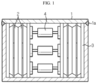
- the conventional welding portion fatigue failure verification device has a structure in which a battery cell 2 and a buffer pad 3 are located inside a housing 1 and a small hydraulic unit is located in a central portion of a battery cell stack.
- the conventional welding portion fatigue failure verification device having the structure may partially help to design a housing welding portion through simulation of whether a welding portion 1a is damaged by reproducing fatigue accumulation due to repeated expansion and contraction of the battery cell 2 in a plane direction.
- the conventional welding portion fatigue failure verification device having the structure has problems in that it is difficult to apply a uniform force to the entire area of the battery cell and in particular, when a size of a battery module is small, it is difficult to apply a sufficient force because only a very small hydraulic unit may be installed.
- the present disclosure is designed to solve the problems of the related art, and therefore the present disclosure is directed to appropriately designing a welding portion of a module housing by providing an environment similar to an actual swelling environment in a battery module.
- a fatigue failure verification device including: a module housing including a welding portion; a cell stack including a plurality of battery cells accommodated in the module housing; at least one main flexible tube located in a central portion of the cell stack in a stack direction of the cell stack; a main flexible tube frame in which the main flexible tube is accommodated, the main flexible tube frame including a pair of opening portions formed on both sides so that the main flexible tube faces the battery cell; and a pump configured to adjust a pressure applied by the main flexible tube to the battery cell by supplying a fluid to the main flexible tube.
- the fatigue failure verification device may further include a pair of sub-flexible tubs respectively located between an upper plate of the module housing and the cell stack and between the upper plate of the module housing and the main flexible tube frame, and between a lower plate of the module housing and the cell stack and between the lower plate of the module housing and the main flexible tube frame.
- the pump may be configured to individually control an amount of a fluid supplied to the main flexible tube and the sub-flexible tubes.
- the fatigue failure verification device may be located between a pair of support walls, wherein the fatigue failure verification device further includes a plurality of displacement sensors respectively located between a side of the module housing in a longitudinal direction of the module housing and the support wall and between the other side of the module housing in the longitudinal direction of the module housing and the support wall.
- the fatigue failure verification device may further include a pair of buffer pads respectively provided on both outermost sides of the cell stack in the stack direction of the cell stack.
- a plurality of main flexible tubes may be provided, wherein the plurality of main flexible tubes are stacked in a width direction of the battery cell in the main flexible tube frame.
- a plurality of main flexible tubes may be provided, wherein the plurality of main flexible tubes are stacked in a longitudinal direction of the battery cell in the main flexible tube frame.
- a plurality of main flexible tubes may be provided, wherein the plurality of main flexible tubes are stacked in a width direction and a longitudinal direction of the battery cell in the main flexible tube frame.
- the pump may be configured to individually control an amount of a fluid supplied to the plurality of main flexible tubes.
- the fatigue failure verification device may further include a pair of sub-flexible tubes respectively located between an upper plate and a lower plate of the module housing and the cell stack, and between the upper plate and the lower plate of the module housing and the main flexible tube frame, wherein the pump is configured to individually control an amount of a fluid supplied to the plurality of main flexible tubes and the pair of sub-flexible tubes.
- a welding portion of a module housing may be appropriately designed by providing an environment similar to an actual swelling environment in a battery module.
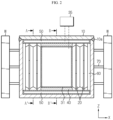
- a fatigue failure verification device includes a module housing 10, a cell stack including a plurality of battery cells 20, a main flexible tube 31, a pump 35, and a main flexible tube frame 40.
- the fatigue failure verification device may further include a pair of sub-flexible tubes 50 and/or a pair of buffer pads 60 and/or a plurality of displacement sensors 70, in addition to the above elements.
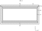
- the module housing 10 may be formed by welding a plurality of plates, and thus, a welding portion 10a is formed on a part of the module housing 10.
- the cell stack is accommodated in the module housing 10.
- the battery cells 20 constituting the cell stack may be, for example, pouch-type battery cells.
- the battery cell 20 extends in a width direction (direction parallel to a Y-axis) of the module housing 10 in the module housing 10.
- a longitudinal direction (direction parallel to the Y-axis) of the battery cell 20 and the width direction (direction parallel to the Y-axis) of the housing 10 are the same direction.
- the battery cell 20 includes a pair of electrode leads 21 drawn out in the same direction or opposite directions in the longitudinal direction (direction parallel to the Y-axis) of the battery cell 20.
- the main flexible tube 31 is located in a central portion of the cell stack in a stack direction (direction parallel to an X-axis) of the cell stack. That is, the main flexible tube 31 is located between the battery cells 20 located in the central portion from among the plurality of battery cells 20 constituting the cell stack.
- the main flexible tube 31 expands due to a fluid supplied from the pump 35, and thus, presses the battery cells 20 located on both sides of the main flexible tube 31 toward side walls of the module housing 10.
- the fatigue failure verification device according to First Embodiment of the present disclosure illustrated in FIGS. 2 through 4 includes one main flexible tube 31.
- the pump 35 is provided outside the module housing 10, and adjusts a pressure applied by the main flexible tube 31 to the battery cell 20 by supplying a fluid to the main flexible tube 31.
- the fatigue failure verification device may further include the pair of sub-flexible tubes 50 in addition to the main flexible tube 31.
- the pump 35 may individually adjust the amount of a fluid supplied to the main flexible tube 31 and the sub-flexible tubes 50.
- the fatigue failure verification device may include a plurality of main flexible tubes 32, 33, 34.
- the pump 35 may individually adjust the amount of a fluid supplied to the plurality of main flexible tubes 32, 33, 34.
- the fatigue failure verification device includes the plurality of main flexible tubes 32, 33, 34 and also includes the pair of sub-flexible tubes 50
- the pump 35 may individually adjust the amount of a fluid supplied to the plurality of main flexible tubes 32, 33, 34 and the pair of sub-flexible tubes 50.
- the pump 35 may include a plurality of unit pumps which are physically separated from one another, in order to individually control the amount of a fluid supplied to the plurality of flexible tubes as described above.
- the main flexible tube frame 40 accommodates the main flexible tube 31 in the module housing 10.
- the main flexible tube frame 40 includes a pair of opening portions formed on both sides so that the main flexible tube 31 faces the battery cell 20.
- a volume expansion direction of the flexible tube frame 40 is limited so that the flexible tube frame 40 does not expand in a direction in which the opening portions are formed, that is, a direction other than the stack direction (direction parallel to the X-axis) of the cell stack.
- the main flexible tube 31 presses the battery cell 20 facing the main flexible tube 31 only in the stack direction (direction parallel to the X-axis) of the cell stack. That is, the main flexible tube 31 corresponds to an element for generating a pressing force according to expansion of the battery cell 20 in a thickness direction (direction parallel to the X-axis) of the battery cell 20 occurring during swelling of the battery cell 20.
- the sub-flexible tube 50 corresponds to an element for generating a pressing force according to expansion of the battery cell 20 in a width direction (direction parallel to a Z-axis) of the battery cell 20 occurring during swelling of the battery cell 20.
- the fatigue failure verification device may include the sub-flexible tube 50.
- a pair of sub-flexible tube 50 may be provided.
- One of the pair of sub-flexible tube 50 is located between an upper plate of the module housing 10 and the cell stack and between the upper plate of the module housing 10 and the main flexible tube frame 40.
- the other one of the pair of sub-flexible tube 50 is located between a lower plate of the module housing 10 and the cell stack and between the lower plate of the module housing 10 and the main flexible tube frame 40.
- the pair of buffer pads 60 are respectively provided on both outermost sides of the cell stack in the stack direction (direction parallel to the X-axis) of the cell stack.
- a plurality of displacement sensors 70 may be respectively provided on a side and the other side of the module housing 10 in a longitudinal direction of the module housing 10.
- the fatigue failure verification device may be located between a pair of support walls W.
- the plurality of displacement sensors 70 are respectively located between a side of the module housing 10 in the longitudinal direction of the module housing 10 and the support wall W and between the other side of the module housing 10 in the longitudinal direction of the module housing 10 and the support wall W.
- the displacement sensor 70 measures the amount of deformation.
- a fatigue failure verification device according to Second Embodiment of the present disclosure illustrated in FIGS. 5 and 6 a fatigue failure verification device according to Third Embodiment of the present disclosure illustrated in FIGS. 7 and 8 , and a fatigue failure verification device according to Fourth Embodiment of the present disclosure illustrated in FIGS. 9 and 10 are different in the number of the main flexible tubes 32, 33, 34 and an arrangement in the main flexible tube frame 40, but other elements are substantially the same and effects thereof are also substantially very similar.
- the fatigue failure verification device includes a plurality of main flexible tubes 32, and the plurality of main flexible tubes 32 are staked in the width direction (direction parallel to the Z-axis) of the battery cell 20 in the main flexible tube frame 40.
- the pump 35 may individually control the amount of a fluid supplied to each main flexible tube 32.
- the plurality of main flexible tubes 32 may press with different forces according to positions in the width direction of the battery cell 20.
- the degree of volume expansion due to swelling may vary according to positions in the width direction of the battery cell 20 during swelling of the battery cell 20. Because the fatigue failure verification device according to Second Embodiment of the present disclosure may allow the plurality of main flexible tubes 32 to press the battery cell 20 with different forces, an environment similar to an actual swelling environment may be created.
- the fatigue failure verification device includes a plurality of main flexible tubes 33, and the plurality of main flexible tubes 33 are stacked in the longitudinal direction (direction parallel to the Y-axis) of the battery cell 20 in the main flexible tube frame 40.
- the pump 35 may individually control the amount of a fluid supplied to each main flexible tube 33.
- the plurality of main flexible tubes 33 may press with different forces according to positions in the longitudinal direction of the battery cell 20.
- the degree of volume expansion due to swelling may vary according to positions in the longitudinal direction of the battery cell 20 during swelling of the battery cell 20. Because the fatigue failure verification device according to Third Embodiment of the present disclosure may allow the plurality of main flexible tubes 33 to press the battery cell 20 with different forces, an environment similar to an actual swelling environment may be created.
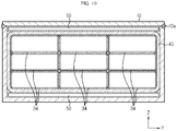
- the fatigue failure verification device includes a plurality of main flexible tubes 34, and the plurality of main flexible tubes 34 are stacked in the longitudinal direction and the width direction of the battery cell 20 in the main flexible tube frame 40.
- the pump 35 may individually control the amount of a fluid supplied to each main flexible tube 34.
- the plurality of main flexible tubes 34 may press with different forces according to positions in the longitudinal direction and the width direction of the battery cell 20.
- the degree of volume expansion due to swelling may vary according to positions in the longitudinal direction and the width direction of the battery cell 20 during swelling of the battery cell 20. Because the fatigue failure verification device according to Fourth Embodiment of the present disclosure may allow the plurality of main flexible tubes 34 to press the battery cell 20 with different forces, an environment similar to an actual swelling environment may be created.
Landscapes
- Chemical & Material Sciences (AREA)
- Health & Medical Sciences (AREA)
- Life Sciences & Earth Sciences (AREA)
- General Physics & Mathematics (AREA)
- Physics & Mathematics (AREA)
- Engineering & Computer Science (AREA)
- Biochemistry (AREA)
- General Health & Medical Sciences (AREA)
- Immunology (AREA)
- Pathology (AREA)
- Analytical Chemistry (AREA)
- Electrochemistry (AREA)
- Chemical Kinetics & Catalysis (AREA)
- Manufacturing & Machinery (AREA)
- General Chemical & Material Sciences (AREA)
- Food Science & Technology (AREA)
- Medicinal Chemistry (AREA)
- Aviation & Aerospace Engineering (AREA)
- Battery Mounting, Suspending (AREA)
- Investigating Strength Of Materials By Application Of Mechanical Stress (AREA)
Applications Claiming Priority (2)
| Application Number | Priority Date | Filing Date | Title |
|---|---|---|---|
| KR1020200149662A KR102815957B1 (ko) | 2020-11-10 | 2020-11-10 | 배터리 모듈의 하우징 용접부에 대한 피로파손 검증 장치 |
| PCT/KR2021/016282 WO2022103132A1 (ko) | 2020-11-10 | 2021-11-09 | 배터리 모듈의 하우징 용접부에 대한 피로파손 검증 장치 |
Publications (3)
| Publication Number | Publication Date |
|---|---|
| EP4151982A1 true EP4151982A1 (de) | 2023-03-22 |
| EP4151982A4 EP4151982A4 (de) | 2023-12-20 |
| EP4151982B1 EP4151982B1 (de) | 2025-10-08 |
Family
ID=81602543
Family Applications (1)
| Application Number | Title | Priority Date | Filing Date |
|---|---|---|---|
| EP21892299.5A Active EP4151982B1 (de) | 2020-11-10 | 2021-11-09 | Vorrichtung zur inspektion von ermüdungsbrüchen eines gehäuseschweissteils eines batteriemoduls |
Country Status (7)
| Country | Link |
|---|---|
| US (1) | US20230375449A1 (de) |
| EP (1) | EP4151982B1 (de) |
| JP (1) | JP7525721B2 (de) |
| KR (1) | KR102815957B1 (de) |
| CN (1) | CN115698669A (de) |
| ES (1) | ES3058395T3 (de) |
| WO (1) | WO2022103132A1 (de) |
Cited By (1)
| Publication number | Priority date | Publication date | Assignee | Title |
|---|---|---|---|---|
| KR20230009620A (ko) * | 2021-07-09 | 2023-01-17 | 주식회사 엘지에너지솔루션 | 전지 모듈 가압 시험 장치 및 방법 |
Families Citing this family (1)
| Publication number | Priority date | Publication date | Assignee | Title |
|---|---|---|---|---|
| KR20240098475A (ko) * | 2022-12-21 | 2024-06-28 | 주식회사 엘지에너지솔루션 | 자동차용 전지 모듈 프레임의 용접부 가속피로 평가장치 |
Family Cites Families (23)
| Publication number | Priority date | Publication date | Assignee | Title |
|---|---|---|---|---|
| KR101108564B1 (ko) * | 2009-11-02 | 2012-01-30 | 한국표준과학연구원 | 내압성 실험장치 및 그 장치를 이용한 내압성 실험방법 |
| KR101209678B1 (ko) * | 2009-11-25 | 2012-12-10 | 기아자동차주식회사 | 연료전지 스택의 면압 조절 장치 |
| CN201653812U (zh) | 2010-05-28 | 2010-11-24 | 哈尔滨光宇电源股份有限公司 | 方形锂离子电池铝壳气胀强度的测量装置 |
| JP2012064508A (ja) | 2010-09-17 | 2012-03-29 | Hitachi Maxell Energy Ltd | 電池試験方法、及び電池試験装置 |
| JP2012114030A (ja) * | 2010-11-26 | 2012-06-14 | Valeo Japan Co Ltd | バッテリ温度調整装置 |
| JP2012221773A (ja) * | 2011-04-11 | 2012-11-12 | Toyota Motor Corp | 固体電池及び固体電池システム |
| US20190006699A1 (en) * | 2013-01-16 | 2019-01-03 | Sion Power Corporation | Pressure and/or temperature management in electrochemical systems |
| JP6026450B2 (ja) | 2014-02-26 | 2016-11-16 | エスペック株式会社 | 圧壊試験装置および圧壊試験方法 |
| KR101962526B1 (ko) * | 2014-03-17 | 2019-03-26 | 닛산 지도우샤 가부시키가이샤 | 배터리 셀의 가압 장치 |
| US10074996B2 (en) * | 2014-08-29 | 2018-09-11 | The Regents Of The University Of Michigan | Bulk force in a battery pack and its application to state of charge estimation |
| DE102014217425A1 (de) * | 2014-09-01 | 2016-03-03 | Robert Bosch Gmbh | Spannvorrichtung für Batteriezellen sowie Batteriemodul, Batterie, Batteriesystem, Fahrzeug und Verfahren zur Herstellung eines Batteriemoduls |
| CN204255553U (zh) | 2014-12-08 | 2015-04-08 | 宁德新能源科技有限公司 | 电池模组的电池膨胀力测试装置 |
| KR102308635B1 (ko) * | 2015-04-17 | 2021-10-05 | 삼성에스디아이 주식회사 | 배터리 모듈 |
| KR102018301B1 (ko) * | 2016-09-01 | 2019-09-04 | 주식회사 엘지화학 | 배터리 모듈 및 그 제조 방법 |
| JP2018106930A (ja) * | 2016-12-27 | 2018-07-05 | 日産自動車株式会社 | バッテリセルの製造方法および加圧マガジン |
| JP2018116914A (ja) * | 2017-01-20 | 2018-07-26 | トヨタ自動車株式会社 | 電池モジュール |
| KR102357026B1 (ko) * | 2017-06-14 | 2022-01-28 | 에스케이온 주식회사 | 전지셀 테스트 장치 |
| WO2019017994A1 (en) * | 2017-07-21 | 2019-01-24 | Quantumscape Corporation | ACTIVE AND PASSIVE BATTERY PRESSURE MANAGEMENT |
| DE102018204220A1 (de) * | 2018-03-20 | 2019-09-26 | Volkswagen Aktiengesellschaft | Batterie |
| KR102106451B1 (ko) * | 2018-06-18 | 2020-05-07 | 비씨에스테크놀러지 주식회사 | 배터리 압축 및 관통 시험을 위한 다축 압축 관통 시험 장치 |
| HUE071136T2 (hu) * | 2020-03-27 | 2025-08-28 | Samsung Sdi Co Ltd | Fluidumrugóval nyomás alá helyezett akkumulátorköteg |
| KR102773568B1 (ko) * | 2020-07-22 | 2025-02-27 | 주식회사 엘지에너지솔루션 | 전지 모듈, 전지 모듈 시스템 및 전지 모듈을 포함하는 전지 팩 |
| KR20230083578A (ko) * | 2021-12-03 | 2023-06-12 | 주식회사 엘지에너지솔루션 | 스웰링 가속 시험 장치 |
-
2020
- 2020-11-10 KR KR1020200149662A patent/KR102815957B1/ko active Active
-
2021
- 2021-11-09 EP EP21892299.5A patent/EP4151982B1/de active Active
- 2021-11-09 JP JP2023502839A patent/JP7525721B2/ja active Active
- 2021-11-09 ES ES21892299T patent/ES3058395T3/es active Active
- 2021-11-09 US US18/031,423 patent/US20230375449A1/en active Pending
- 2021-11-09 WO PCT/KR2021/016282 patent/WO2022103132A1/ko not_active Ceased
- 2021-11-09 CN CN202180039955.6A patent/CN115698669A/zh active Pending
Cited By (2)
| Publication number | Priority date | Publication date | Assignee | Title |
|---|---|---|---|---|
| KR20230009620A (ko) * | 2021-07-09 | 2023-01-17 | 주식회사 엘지에너지솔루션 | 전지 모듈 가압 시험 장치 및 방법 |
| EP4246656A4 (de) * | 2021-07-09 | 2025-03-19 | LG Energy Solution, Ltd. | Batteriemoduldrucktestvorrichtung und -verfahren |
Also Published As
| Publication number | Publication date |
|---|---|
| CN115698669A (zh) | 2023-02-03 |
| EP4151982A4 (de) | 2023-12-20 |
| KR102815957B1 (ko) | 2025-05-30 |
| US20230375449A1 (en) | 2023-11-23 |
| ES3058395T3 (es) | 2026-03-10 |
| WO2022103132A1 (ko) | 2022-05-19 |
| JP7525721B2 (ja) | 2024-07-30 |
| EP4151982B1 (de) | 2025-10-08 |
| JP2023534471A (ja) | 2023-08-09 |
| KR20220063611A (ko) | 2022-05-17 |
Similar Documents
| Publication | Publication Date | Title |
|---|---|---|
| CN110311068B (zh) | 电池组 | |
| EP4151982A1 (de) | Vorrichtung zur inspektion von ermüdungsbrüchen eines gehäuseschweissteils eines batteriemoduls | |
| CN106133944B (zh) | 电池单元的加压装置 | |
| CN112005461B (zh) | 用于对二次电池进行充电和放电的装置 | |
| CN108140774B (zh) | 包括具有改进的结构的端板的电池模块以及用于其的端板构件 | |
| EP3343668A1 (de) | Endplattenanordnung eines batteriemoduls und batteriemodul | |
| JP5636634B2 (ja) | 電極板加圧装置 | |
| JPWO2019003772A1 (ja) | 蓄電装置 | |
| CN107275662B (zh) | 带拉紧装置的燃料电池堆 | |
| EP2845260B1 (de) | Brennstoffzellenstapelanordnung | |
| CN101167197A (zh) | 用于密封的蓄电池的外壳 | |
| JP7540859B2 (ja) | 電池モジュール加圧試験装置および方法 | |
| CN115398692B (zh) | 电极切割装置和包括该电极切割装置的电极制造设备 | |
| CN105144456B (zh) | 绝缘结构体、燃料电池以及燃料电池堆 | |
| KR20240140885A (ko) | 배터리 조립체 및 그 조립 방법 | |
| CN114946063B (zh) | 包括挤压垫的电池单体的挤压夹具和使用该挤压夹具的电池单体的除气方法 | |
| CN112331935A (zh) | 车辆蓄电池模块、车辆和用于制造车辆蓄电池模块的方法 | |
| RU2008103286A (ru) | Пакет электрохимических ячеек | |
| US20240291087A1 (en) | Battery Module Housing for a Battery Module, Battery Module, and Electrical Energy Store | |
| JP6954813B2 (ja) | 燃料電池の製造方法 | |
| JP2009004254A (ja) | 燃料電池スタックの組み立て方法 | |
| JP7791991B2 (ja) | 全固体電池の製造装置及び製造方法 | |
| US12494518B2 (en) | Charging and discharging apparatus comprising spacers for supporting gas pockets of battery cells | |
| EP4661123A1 (de) | Batteriezellenpressvorrichtung zur herstellung einer batteriezelle und batteriezellenherstellungssystem | |
| CN219348031U (zh) | 夹具及膨胀力测试装置 |
Legal Events
| Date | Code | Title | Description |
|---|---|---|---|
| STAA | Information on the status of an ep patent application or granted ep patent |
Free format text: STATUS: THE INTERNATIONAL PUBLICATION HAS BEEN MADE |
|
| PUAI | Public reference made under article 153(3) epc to a published international application that has entered the european phase |
Free format text: ORIGINAL CODE: 0009012 |
|
| STAA | Information on the status of an ep patent application or granted ep patent |
Free format text: STATUS: REQUEST FOR EXAMINATION WAS MADE |
|
| 17P | Request for examination filed |
Effective date: 20221215 |
|
| AK | Designated contracting states |
Kind code of ref document: A1 Designated state(s): AL AT BE BG CH CY CZ DE DK EE ES FI FR GB GR HR HU IE IS IT LI LT LU LV MC MK MT NL NO PL PT RO RS SE SI SK SM TR |
|
| REG | Reference to a national code |
Ref legal event code: R079 Ipc: G01M0005000000 Ref country code: DE Ref legal event code: R079 Ref document number: 602021040236 Country of ref document: DE Free format text: PREVIOUS MAIN CLASS: G01N0003100000 Ipc: G01M0005000000 |
|
| A4 | Supplementary search report drawn up and despatched |
Effective date: 20231122 |
|
| RIC1 | Information provided on ipc code assigned before grant |
Ipc: G01N 3/10 20060101ALI20231116BHEP Ipc: G01M 5/00 20060101AFI20231116BHEP |
|
| DAV | Request for validation of the european patent (deleted) | ||
| DAX | Request for extension of the european patent (deleted) | ||
| GRAP | Despatch of communication of intention to grant a patent |
Free format text: ORIGINAL CODE: EPIDOSNIGR1 |
|
| STAA | Information on the status of an ep patent application or granted ep patent |
Free format text: STATUS: GRANT OF PATENT IS INTENDED |
|
| RIC1 | Information provided on ipc code assigned before grant |
Ipc: G01N 3/10 20060101ALI20250411BHEP Ipc: G01M 5/00 20060101AFI20250411BHEP |
|
| INTG | Intention to grant announced |
Effective date: 20250506 |
|
| GRAS | Grant fee paid |
Free format text: ORIGINAL CODE: EPIDOSNIGR3 |
|
| GRAA | (expected) grant |
Free format text: ORIGINAL CODE: 0009210 |
|
| STAA | Information on the status of an ep patent application or granted ep patent |
Free format text: STATUS: THE PATENT HAS BEEN GRANTED |
|
| AK | Designated contracting states |
Kind code of ref document: B1 Designated state(s): AL AT BE BG CH CY CZ DE DK EE ES FI FR GB GR HR HU IE IS IT LI LT LU LV MC MK MT NL NO PL PT RO RS SE SI SK SM TR |
|
| REG | Reference to a national code |
Ref country code: GB Ref legal event code: FG4D Ref country code: CH Ref legal event code: F10 Free format text: ST27 STATUS EVENT CODE: U-0-0-F10-F00 (AS PROVIDED BY THE NATIONAL OFFICE) Effective date: 20251008 |
|
| REG | Reference to a national code |
Ref country code: DE Ref legal event code: R096 Ref document number: 602021040236 Country of ref document: DE |
|
| P01 | Opt-out of the competence of the unified patent court (upc) registered |
Free format text: CASE NUMBER: UPC_APP_8611_4151982/2025 Effective date: 20251001 |
|
| REG | Reference to a national code |
Ref country code: IE Ref legal event code: FG4D |
|
| PGFP | Annual fee paid to national office [announced via postgrant information from national office to epo] |
Ref country code: DE Payment date: 20251020 Year of fee payment: 5 |
|
| PGFP | Annual fee paid to national office [announced via postgrant information from national office to epo] |
Ref country code: GB Payment date: 20251023 Year of fee payment: 5 |
|
| PGFP | Annual fee paid to national office [announced via postgrant information from national office to epo] |
Ref country code: AT Payment date: 20260113 Year of fee payment: 5 |
|
| PGFP | Annual fee paid to national office [announced via postgrant information from national office to epo] |
Ref country code: FR Payment date: 20251021 Year of fee payment: 5 |
|
| PGFP | Annual fee paid to national office [announced via postgrant information from national office to epo] |
Ref country code: BE Payment date: 20251020 Year of fee payment: 5 |
|
| PGFP | Annual fee paid to national office [announced via postgrant information from national office to epo] |
Ref country code: ES Payment date: 20251215 Year of fee payment: 5 |
|
| REG | Reference to a national code |
Ref country code: NL Ref legal event code: MP Effective date: 20251008 |
|
| PGFP | Annual fee paid to national office [announced via postgrant information from national office to epo] |
Ref country code: HU Payment date: 20260129 Year of fee payment: 5 |
|
| REG | Reference to a national code |
Ref country code: ES Ref legal event code: FG2A Ref document number: 3058395 Country of ref document: ES Kind code of ref document: T3 Effective date: 20260310 |
|
| REG | Reference to a national code |
Ref country code: AT Ref legal event code: MK05 Ref document number: 1845181 Country of ref document: AT Kind code of ref document: T Effective date: 20251008 |
|
| PG25 | Lapsed in a contracting state [announced via postgrant information from national office to epo] |
Ref country code: NL Free format text: LAPSE BECAUSE OF FAILURE TO SUBMIT A TRANSLATION OF THE DESCRIPTION OR TO PAY THE FEE WITHIN THE PRESCRIBED TIME-LIMIT Effective date: 20251008 |
|
| REG | Reference to a national code |
Ref country code: LT Ref legal event code: MG9D |
|
| PG25 | Lapsed in a contracting state [announced via postgrant information from national office to epo] |
Ref country code: NO Free format text: LAPSE BECAUSE OF FAILURE TO SUBMIT A TRANSLATION OF THE DESCRIPTION OR TO PAY THE FEE WITHIN THE PRESCRIBED TIME-LIMIT Effective date: 20260108 |
|
| PG25 | Lapsed in a contracting state [announced via postgrant information from national office to epo] |
Ref country code: HR Free format text: LAPSE BECAUSE OF FAILURE TO SUBMIT A TRANSLATION OF THE DESCRIPTION OR TO PAY THE FEE WITHIN THE PRESCRIBED TIME-LIMIT Effective date: 20251008 Ref country code: FI Free format text: LAPSE BECAUSE OF FAILURE TO SUBMIT A TRANSLATION OF THE DESCRIPTION OR TO PAY THE FEE WITHIN THE PRESCRIBED TIME-LIMIT Effective date: 20251008 Ref country code: AT Free format text: LAPSE BECAUSE OF FAILURE TO SUBMIT A TRANSLATION OF THE DESCRIPTION OR TO PAY THE FEE WITHIN THE PRESCRIBED TIME-LIMIT Effective date: 20251008 |
|
| PG25 | Lapsed in a contracting state [announced via postgrant information from national office to epo] |
Ref country code: RS Free format text: LAPSE BECAUSE OF FAILURE TO SUBMIT A TRANSLATION OF THE DESCRIPTION OR TO PAY THE FEE WITHIN THE PRESCRIBED TIME-LIMIT Effective date: 20260108 |
|
| PG25 | Lapsed in a contracting state [announced via postgrant information from national office to epo] |
Ref country code: IS Free format text: LAPSE BECAUSE OF FAILURE TO SUBMIT A TRANSLATION OF THE DESCRIPTION OR TO PAY THE FEE WITHIN THE PRESCRIBED TIME-LIMIT Effective date: 20260208 |
|
| PG25 | Lapsed in a contracting state [announced via postgrant information from national office to epo] |
Ref country code: PT Free format text: LAPSE BECAUSE OF FAILURE TO SUBMIT A TRANSLATION OF THE DESCRIPTION OR TO PAY THE FEE WITHIN THE PRESCRIBED TIME-LIMIT Effective date: 20260209 |
|
| PG25 | Lapsed in a contracting state [announced via postgrant information from national office to epo] |
Ref country code: PL Free format text: LAPSE BECAUSE OF FAILURE TO SUBMIT A TRANSLATION OF THE DESCRIPTION OR TO PAY THE FEE WITHIN THE PRESCRIBED TIME-LIMIT Effective date: 20251008 |
|
| PG25 | Lapsed in a contracting state [announced via postgrant information from national office to epo] |
Ref country code: LV Free format text: LAPSE BECAUSE OF FAILURE TO SUBMIT A TRANSLATION OF THE DESCRIPTION OR TO PAY THE FEE WITHIN THE PRESCRIBED TIME-LIMIT Effective date: 20251008 |