EP4151982A1 - Apparatus for inspecting fatigue fracture of housing welding part of battery module - Google Patents
Apparatus for inspecting fatigue fracture of housing welding part of battery module Download PDFInfo
- Publication number
- EP4151982A1 EP4151982A1 EP21892299.5A EP21892299A EP4151982A1 EP 4151982 A1 EP4151982 A1 EP 4151982A1 EP 21892299 A EP21892299 A EP 21892299A EP 4151982 A1 EP4151982 A1 EP 4151982A1
- Authority
- EP
- European Patent Office
- Prior art keywords
- main flexible
- flexible tube
- module housing
- verification device
- fatigue failure
- Prior art date
- Legal status (The legal status is an assumption and is not a legal conclusion. Google has not performed a legal analysis and makes no representation as to the accuracy of the status listed.)
- Pending
Links
- 238000003466 welding Methods 0.000 title claims abstract description 21
- 238000012795 verification Methods 0.000 claims abstract description 51
- 239000012530 fluid Substances 0.000 claims abstract description 18
- 238000006073 displacement reaction Methods 0.000 claims description 6
- 230000008961 swelling Effects 0.000 description 18
- 230000008602 contraction Effects 0.000 description 2
- 238000007599 discharging Methods 0.000 description 2
- 230000000694 effects Effects 0.000 description 2
- 238000009825 accumulation Methods 0.000 description 1
- 238000009661 fatigue test Methods 0.000 description 1
- 239000000463 material Substances 0.000 description 1
- 238000012986 modification Methods 0.000 description 1
- 230000004048 modification Effects 0.000 description 1
- 238000004088 simulation Methods 0.000 description 1
Images


Classifications
-
- H—ELECTRICITY
- H01—ELECTRIC ELEMENTS
- H01M—PROCESSES OR MEANS, e.g. BATTERIES, FOR THE DIRECT CONVERSION OF CHEMICAL ENERGY INTO ELECTRICAL ENERGY
- H01M10/00—Secondary cells; Manufacture thereof
- H01M10/42—Methods or arrangements for servicing or maintenance of secondary cells or secondary half-cells
- H01M10/4285—Testing apparatus
-
- G—PHYSICS
- G01—MEASURING; TESTING
- G01N—INVESTIGATING OR ANALYSING MATERIALS BY DETERMINING THEIR CHEMICAL OR PHYSICAL PROPERTIES
- G01N3/00—Investigating strength properties of solid materials by application of mechanical stress
- G01N3/08—Investigating strength properties of solid materials by application of mechanical stress by applying steady tensile or compressive forces
- G01N3/10—Investigating strength properties of solid materials by application of mechanical stress by applying steady tensile or compressive forces generated by pneumatic or hydraulic pressure
-
- G—PHYSICS
- G01—MEASURING; TESTING
- G01M—TESTING STATIC OR DYNAMIC BALANCE OF MACHINES OR STRUCTURES; TESTING OF STRUCTURES OR APPARATUS, NOT OTHERWISE PROVIDED FOR
- G01M5/00—Investigating the elasticity of structures, e.g. deflection of bridges or air-craft wings
- G01M5/0033—Investigating the elasticity of structures, e.g. deflection of bridges or air-craft wings by determining damage, crack or wear
-
- G—PHYSICS
- G01—MEASURING; TESTING
- G01N—INVESTIGATING OR ANALYSING MATERIALS BY DETERMINING THEIR CHEMICAL OR PHYSICAL PROPERTIES
- G01N33/00—Investigating or analysing materials by specific methods not covered by groups G01N1/00 - G01N31/00
- G01N33/0078—Testing material properties on manufactured objects
-
- G—PHYSICS
- G01—MEASURING; TESTING
- G01N—INVESTIGATING OR ANALYSING MATERIALS BY DETERMINING THEIR CHEMICAL OR PHYSICAL PROPERTIES
- G01N33/00—Investigating or analysing materials by specific methods not covered by groups G01N1/00 - G01N31/00
- G01N33/0095—Semiconductive materials
-
- G—PHYSICS
- G01—MEASURING; TESTING
- G01N—INVESTIGATING OR ANALYSING MATERIALS BY DETERMINING THEIR CHEMICAL OR PHYSICAL PROPERTIES
- G01N2203/00—Investigating strength properties of solid materials by application of mechanical stress
- G01N2203/0058—Kind of property studied
- G01N2203/006—Crack, flaws, fracture or rupture
- G01N2203/0067—Fracture or rupture
-
- G—PHYSICS
- G01—MEASURING; TESTING
- G01N—INVESTIGATING OR ANALYSING MATERIALS BY DETERMINING THEIR CHEMICAL OR PHYSICAL PROPERTIES
- G01N2203/00—Investigating strength properties of solid materials by application of mechanical stress
- G01N2203/0058—Kind of property studied
- G01N2203/0069—Fatigue, creep, strain-stress relations or elastic constants
- G01N2203/0073—Fatigue
-
- G—PHYSICS
- G01—MEASURING; TESTING
- G01N—INVESTIGATING OR ANALYSING MATERIALS BY DETERMINING THEIR CHEMICAL OR PHYSICAL PROPERTIES
- G01N2203/00—Investigating strength properties of solid materials by application of mechanical stress
- G01N2203/02—Details not specific for a particular testing method
- G01N2203/026—Specifications of the specimen
- G01N2203/0296—Welds
-
- Y—GENERAL TAGGING OF NEW TECHNOLOGICAL DEVELOPMENTS; GENERAL TAGGING OF CROSS-SECTIONAL TECHNOLOGIES SPANNING OVER SEVERAL SECTIONS OF THE IPC; TECHNICAL SUBJECTS COVERED BY FORMER USPC CROSS-REFERENCE ART COLLECTIONS [XRACs] AND DIGESTS
- Y02—TECHNOLOGIES OR APPLICATIONS FOR MITIGATION OR ADAPTATION AGAINST CLIMATE CHANGE
- Y02E—REDUCTION OF GREENHOUSE GAS [GHG] EMISSIONS, RELATED TO ENERGY GENERATION, TRANSMISSION OR DISTRIBUTION
- Y02E60/00—Enabling technologies; Technologies with a potential or indirect contribution to GHG emissions mitigation
- Y02E60/10—Energy storage using batteries
Definitions
- the present disclosure relates to a fatigue failure verification device for a housing welding portion of a battery module, and more particularly, to a fatigue failure verification device configured to implement a phenomenon in which repeated fatigue accumulates in a housing according to swelling of battery cells accommodated in the housing in a battery module as close to reality as possible.
- the conventional welding portion fatigue failure verification device has a structure in which a battery cell 2 and a buffer pad 3 are located inside a housing 1 and a small hydraulic unit is located in a central portion of a battery cell stack.
- the conventional welding portion fatigue failure verification device having the structure may partially help to design a housing welding portion through simulation of whether a welding portion 1a is damaged by reproducing fatigue accumulation due to repeated expansion and contraction of the battery cell 2 in a plane direction.
- the conventional welding portion fatigue failure verification device having the structure has problems in that it is difficult to apply a uniform force to the entire area of the battery cell and in particular, when a size of a battery module is small, it is difficult to apply a sufficient force because only a very small hydraulic unit may be installed.
- the present disclosure is designed to solve the problems of the related art, and therefore the present disclosure is directed to appropriately designing a welding portion of a module housing by providing an environment similar to an actual swelling environment in a battery module.
- a fatigue failure verification device including: a module housing including a welding portion; a cell stack including a plurality of battery cells accommodated in the module housing; at least one main flexible tube located in a central portion of the cell stack in a stack direction of the cell stack; a main flexible tube frame in which the main flexible tube is accommodated, the main flexible tube frame including a pair of opening portions formed on both sides so that the main flexible tube faces the battery cell; and a pump configured to adjust a pressure applied by the main flexible tube to the battery cell by supplying a fluid to the main flexible tube.
- the fatigue failure verification device may further include a pair of sub-flexible tubs respectively located between an upper plate of the module housing and the cell stack and between the upper plate of the module housing and the main flexible tube frame, and between a lower plate of the module housing and the cell stack and between the lower plate of the module housing and the main flexible tube frame.
- the pump may be configured to individually control an amount of a fluid supplied to the main flexible tube and the sub-flexible tubes.
- the fatigue failure verification device may be located between a pair of support walls, wherein the fatigue failure verification device further includes a plurality of displacement sensors respectively located between a side of the module housing in a longitudinal direction of the module housing and the support wall and between the other side of the module housing in the longitudinal direction of the module housing and the support wall.
- the fatigue failure verification device may further include a pair of buffer pads respectively provided on both outermost sides of the cell stack in the stack direction of the cell stack.
- a plurality of main flexible tubes may be provided, wherein the plurality of main flexible tubes are stacked in a width direction of the battery cell in the main flexible tube frame.
- a plurality of main flexible tubes may be provided, wherein the plurality of main flexible tubes are stacked in a longitudinal direction of the battery cell in the main flexible tube frame.
- a plurality of main flexible tubes may be provided, wherein the plurality of main flexible tubes are stacked in a width direction and a longitudinal direction of the battery cell in the main flexible tube frame.
- the pump may be configured to individually control an amount of a fluid supplied to the plurality of main flexible tubes.
- the fatigue failure verification device may further include a pair of sub-flexible tubes respectively located between an upper plate and a lower plate of the module housing and the cell stack, and between the upper plate and the lower plate of the module housing and the main flexible tube frame, wherein the pump is configured to individually control an amount of a fluid supplied to the plurality of main flexible tubes and the pair of sub-flexible tubes.
- a welding portion of a module housing may be appropriately designed by providing an environment similar to an actual swelling environment in a battery module.
- a fatigue failure verification device includes a module housing 10, a cell stack including a plurality of battery cells 20, a main flexible tube 31, a pump 35, and a main flexible tube frame 40.
- the fatigue failure verification device may further include a pair of sub-flexible tubes 50 and/or a pair of buffer pads 60 and/or a plurality of displacement sensors 70, in addition to the above elements.
- the module housing 10 may be formed by welding a plurality of plates, and thus, a welding portion 10a is formed on a part of the module housing 10.
- the cell stack is accommodated in the module housing 10.
- the battery cells 20 constituting the cell stack may be, for example, pouch-type battery cells.
- the battery cell 20 extends in a width direction (direction parallel to a Y-axis) of the module housing 10 in the module housing 10.
- a longitudinal direction (direction parallel to the Y-axis) of the battery cell 20 and the width direction (direction parallel to the Y-axis) of the housing 10 are the same direction.
- the battery cell 20 includes a pair of electrode leads 21 drawn out in the same direction or opposite directions in the longitudinal direction (direction parallel to the Y-axis) of the battery cell 20.
- the main flexible tube 31 is located in a central portion of the cell stack in a stack direction (direction parallel to an X-axis) of the cell stack. That is, the main flexible tube 31 is located between the battery cells 20 located in the central portion from among the plurality of battery cells 20 constituting the cell stack.
- the main flexible tube 31 expands due to a fluid supplied from the pump 35, and thus, presses the battery cells 20 located on both sides of the main flexible tube 31 toward side walls of the module housing 10.
- the fatigue failure verification device according to First Embodiment of the present disclosure illustrated in FIGS. 2 through 4 includes one main flexible tube 31.
- the pump 35 is provided outside the module housing 10, and adjusts a pressure applied by the main flexible tube 31 to the battery cell 20 by supplying a fluid to the main flexible tube 31.
- the fatigue failure verification device may further include the pair of sub-flexible tubes 50 in addition to the main flexible tube 31.
- the pump 35 may individually adjust the amount of a fluid supplied to the main flexible tube 31 and the sub-flexible tubes 50.
- the fatigue failure verification device may include a plurality of main flexible tubes 32, 33, 34.
- the pump 35 may individually adjust the amount of a fluid supplied to the plurality of main flexible tubes 32, 33, 34.
- the fatigue failure verification device includes the plurality of main flexible tubes 32, 33, 34 and also includes the pair of sub-flexible tubes 50
- the pump 35 may individually adjust the amount of a fluid supplied to the plurality of main flexible tubes 32, 33, 34 and the pair of sub-flexible tubes 50.
- the pump 35 may include a plurality of unit pumps which are physically separated from one another, in order to individually control the amount of a fluid supplied to the plurality of flexible tubes as described above.
- the main flexible tube frame 40 accommodates the main flexible tube 31 in the module housing 10.
- the main flexible tube frame 40 includes a pair of opening portions formed on both sides so that the main flexible tube 31 faces the battery cell 20.
- a volume expansion direction of the flexible tube frame 40 is limited so that the flexible tube frame 40 does not expand in a direction in which the opening portions are formed, that is, a direction other than the stack direction (direction parallel to the X-axis) of the cell stack.
- the main flexible tube 31 presses the battery cell 20 facing the main flexible tube 31 only in the stack direction (direction parallel to the X-axis) of the cell stack. That is, the main flexible tube 31 corresponds to an element for generating a pressing force according to expansion of the battery cell 20 in a thickness direction (direction parallel to the X-axis) of the battery cell 20 occurring during swelling of the battery cell 20.
- the sub-flexible tube 50 corresponds to an element for generating a pressing force according to expansion of the battery cell 20 in a width direction (direction parallel to a Z-axis) of the battery cell 20 occurring during swelling of the battery cell 20.
- the fatigue failure verification device may include the sub-flexible tube 50.
- a pair of sub-flexible tube 50 may be provided.
- One of the pair of sub-flexible tube 50 is located between an upper plate of the module housing 10 and the cell stack and between the upper plate of the module housing 10 and the main flexible tube frame 40.
- the other one of the pair of sub-flexible tube 50 is located between a lower plate of the module housing 10 and the cell stack and between the lower plate of the module housing 10 and the main flexible tube frame 40.
- the pair of buffer pads 60 are respectively provided on both outermost sides of the cell stack in the stack direction (direction parallel to the X-axis) of the cell stack.
- a plurality of displacement sensors 70 may be respectively provided on a side and the other side of the module housing 10 in a longitudinal direction of the module housing 10.
- the fatigue failure verification device may be located between a pair of support walls W.
- the plurality of displacement sensors 70 are respectively located between a side of the module housing 10 in the longitudinal direction of the module housing 10 and the support wall W and between the other side of the module housing 10 in the longitudinal direction of the module housing 10 and the support wall W.
- the displacement sensor 70 measures the amount of deformation.
- a fatigue failure verification device according to Second Embodiment of the present disclosure illustrated in FIGS. 5 and 6 a fatigue failure verification device according to Third Embodiment of the present disclosure illustrated in FIGS. 7 and 8 , and a fatigue failure verification device according to Fourth Embodiment of the present disclosure illustrated in FIGS. 9 and 10 are different in the number of the main flexible tubes 32, 33, 34 and an arrangement in the main flexible tube frame 40, but other elements are substantially the same and effects thereof are also substantially very similar.
- the fatigue failure verification device includes a plurality of main flexible tubes 32, and the plurality of main flexible tubes 32 are staked in the width direction (direction parallel to the Z-axis) of the battery cell 20 in the main flexible tube frame 40.
- the pump 35 may individually control the amount of a fluid supplied to each main flexible tube 32.
- the plurality of main flexible tubes 32 may press with different forces according to positions in the width direction of the battery cell 20.
- the degree of volume expansion due to swelling may vary according to positions in the width direction of the battery cell 20 during swelling of the battery cell 20. Because the fatigue failure verification device according to Second Embodiment of the present disclosure may allow the plurality of main flexible tubes 32 to press the battery cell 20 with different forces, an environment similar to an actual swelling environment may be created.
- the fatigue failure verification device includes a plurality of main flexible tubes 33, and the plurality of main flexible tubes 33 are stacked in the longitudinal direction (direction parallel to the Y-axis) of the battery cell 20 in the main flexible tube frame 40.
- the pump 35 may individually control the amount of a fluid supplied to each main flexible tube 33.
- the plurality of main flexible tubes 33 may press with different forces according to positions in the longitudinal direction of the battery cell 20.
- the degree of volume expansion due to swelling may vary according to positions in the longitudinal direction of the battery cell 20 during swelling of the battery cell 20. Because the fatigue failure verification device according to Third Embodiment of the present disclosure may allow the plurality of main flexible tubes 33 to press the battery cell 20 with different forces, an environment similar to an actual swelling environment may be created.
- the fatigue failure verification device includes a plurality of main flexible tubes 34, and the plurality of main flexible tubes 34 are stacked in the longitudinal direction and the width direction of the battery cell 20 in the main flexible tube frame 40.
- the pump 35 may individually control the amount of a fluid supplied to each main flexible tube 34.
- the plurality of main flexible tubes 34 may press with different forces according to positions in the longitudinal direction and the width direction of the battery cell 20.
- the degree of volume expansion due to swelling may vary according to positions in the longitudinal direction and the width direction of the battery cell 20 during swelling of the battery cell 20. Because the fatigue failure verification device according to Fourth Embodiment of the present disclosure may allow the plurality of main flexible tubes 34 to press the battery cell 20 with different forces, an environment similar to an actual swelling environment may be created.
Landscapes
- Chemical & Material Sciences (AREA)
- Health & Medical Sciences (AREA)
- Life Sciences & Earth Sciences (AREA)
- Physics & Mathematics (AREA)
- General Physics & Mathematics (AREA)
- Analytical Chemistry (AREA)
- Biochemistry (AREA)
- General Health & Medical Sciences (AREA)
- Immunology (AREA)
- Pathology (AREA)
- Engineering & Computer Science (AREA)
- Food Science & Technology (AREA)
- Medicinal Chemistry (AREA)
- Aviation & Aerospace Engineering (AREA)
- Manufacturing & Machinery (AREA)
- Chemical Kinetics & Catalysis (AREA)
- Electrochemistry (AREA)
- General Chemical & Material Sciences (AREA)
- Battery Mounting, Suspending (AREA)
- Investigating Strength Of Materials By Application Of Mechanical Stress (AREA)
Abstract
Description
- The present disclosure relates to a fatigue failure verification device for a housing welding portion of a battery module, and more particularly, to a fatigue failure verification device configured to implement a phenomenon in which repeated fatigue accumulates in a housing according to swelling of battery cells accommodated in the housing in a battery module as close to reality as possible.
- The present application claims priority to
Korean Patent Application No. 10-2020-0149662 filed on November 10, 2020 - As charging and discharging of a battery module is repeated and expansion and contraction of a battery cell due to swelling of the battery cell repeatedly occurs, fatigue may accumulate in a welding portion of a housing in which the battery cell is accommodated, resulting in damage to the housing. In order to prevent damage to the welding portion, a material, a thickness, a depth, etc. of the welding portion between plates constituting the housing should be designed by considering the swelling of the battery cell. However, because a fatigue test through charging and discharging takes a lot of time, there is a need to develop a verification device capable of providing conditions similar to actual conditions.
- Referring to
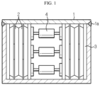
FIG. 1 , a conventional welding portion fatigue failure verification device is illustrated. The conventional welding portion fatigue failure verification device has a structure in which abattery cell 2 and abuffer pad 3 are located inside a housing 1 and a small hydraulic unit is located in a central portion of a battery cell stack. - The conventional welding portion fatigue failure verification device having the structure may partially help to design a housing welding portion through simulation of whether a
welding portion 1a is damaged by reproducing fatigue accumulation due to repeated expansion and contraction of thebattery cell 2 in a plane direction. - However, the conventional welding portion fatigue failure verification device having the structure has problems in that it is difficult to apply a uniform force to the entire area of the battery cell and in particular, when a size of a battery module is small, it is difficult to apply a sufficient force because only a very small hydraulic unit may be installed.
- Accordingly, there is a need to develop a welding portion fatigue failure verification device capable of providing an environment similar to an actual swelling environment in a battery module, when compared to the conventional welding portion fatigue failure verification device.
- The present disclosure is designed to solve the problems of the related art, and therefore the present disclosure is directed to appropriately designing a welding portion of a module housing by providing an environment similar to an actual swelling environment in a battery module.
- However, the technical purpose to be solved by the present disclosure is not limited to the above, and other objects not mentioned herein will be clearly understood by one of ordinary skill in the art from the following disclosure.
- In one aspect of the present disclosure, there is provided a fatigue failure verification device including: a module housing including a welding portion; a cell stack including a plurality of battery cells accommodated in the module housing; at least one main flexible tube located in a central portion of the cell stack in a stack direction of the cell stack; a main flexible tube frame in which the main flexible tube is accommodated, the main flexible tube frame including a pair of opening portions formed on both sides so that the main flexible tube faces the battery cell; and a pump configured to adjust a pressure applied by the main flexible tube to the battery cell by supplying a fluid to the main flexible tube.
- The fatigue failure verification device may further include a pair of sub-flexible tubs respectively located between an upper plate of the module housing and the cell stack and between the upper plate of the module housing and the main flexible tube frame, and between a lower plate of the module housing and the cell stack and between the lower plate of the module housing and the main flexible tube frame.
- The pump may be configured to individually control an amount of a fluid supplied to the main flexible tube and the sub-flexible tubes.
- The fatigue failure verification device may be located between a pair of support walls, wherein the fatigue failure verification device further includes a plurality of displacement sensors respectively located between a side of the module housing in a longitudinal direction of the module housing and the support wall and between the other side of the module housing in the longitudinal direction of the module housing and the support wall.
- The fatigue failure verification device may further include a pair of buffer pads respectively provided on both outermost sides of the cell stack in the stack direction of the cell stack.
- A plurality of main flexible tubes may be provided, wherein the plurality of main flexible tubes are stacked in a width direction of the battery cell in the main flexible tube frame.
- A plurality of main flexible tubes may be provided, wherein the plurality of main flexible tubes are stacked in a longitudinal direction of the battery cell in the main flexible tube frame.
- A plurality of main flexible tubes may be provided, wherein the plurality of main flexible tubes are stacked in a width direction and a longitudinal direction of the battery cell in the main flexible tube frame.
- The pump may be configured to individually control an amount of a fluid supplied to the plurality of main flexible tubes.
- The fatigue failure verification device may further include a pair of sub-flexible tubes respectively located between an upper plate and a lower plate of the module housing and the cell stack, and between the upper plate and the lower plate of the module housing and the main flexible tube frame, wherein the pump is configured to individually control an amount of a fluid supplied to the plurality of main flexible tubes and the pair of sub-flexible tubes.
- According to an aspect of the present disclosure, a welding portion of a module housing may be appropriately designed by providing an environment similar to an actual swelling environment in a battery module.
- The accompanying drawings illustrate a preferred embodiment of the present disclosure and together with the foregoing disclosure, serve to provide further understanding of the technical features of the present disclosure, and thus, the present disclosure is not construed as being limited to the drawing.
-
FIG. 1 is a view illustrating a conventional welding portion fatigue failure verification device. -
FIGS. 2 through 4 are views illustrating a fatigue failure verification device according to First Embodiment of the present disclosure. -
FIGS. 5 and6 are views illustrating a fatigue failure verification device according to Second Embodiment of the present disclosure. -
FIGS. 7 and8 are views illustrating a fatigue failure verification device according to Third Embodiment of the present disclosure. -
FIGS. 9 and10 are views illustrating a fatigue failure verification device according to Fourth Embodiment of the present disclosure. - Hereinafter, preferred embodiments of the present disclosure will be described in detail with reference to the accompanying drawings. Prior to the description, it should be understood that the terms used in the specification and the appended claims should not be construed as limited to general and dictionary meanings, but interpreted based on the meanings and concepts corresponding to technical aspects of the present disclosure on the basis of the principle that the inventor is allowed to define terms appropriately for the best explanation. Therefore, the description proposed herein is just a preferable example for the purpose of illustrations only, not intended to limit the scope of the disclosure, so it should be understood that other equivalents and modifications could be made thereto without departing from the scope of the disclosure.
- Referring to
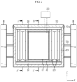
FIGS. 2 through 4 , a fatigue failure verification device according to First Embodiment of the present disclosure includes amodule housing 10, a cell stack including a plurality ofbattery cells 20, a mainflexible tube 31, apump 35, and a mainflexible tube frame 40. The fatigue failure verification device may further include a pair ofsub-flexible tubes 50 and/or a pair ofbuffer pads 60 and/or a plurality ofdisplacement sensors 70, in addition to the above elements. - The
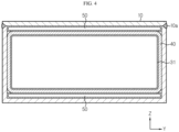
module housing 10 may be formed by welding a plurality of plates, and thus, awelding portion 10a is formed on a part of themodule housing 10. - The cell stack is accommodated in the
module housing 10. Thebattery cells 20 constituting the cell stack may be, for example, pouch-type battery cells. Thebattery cell 20 extends in a width direction (direction parallel to a Y-axis) of themodule housing 10 in themodule housing 10. - That is, in the specification, a longitudinal direction (direction parallel to the Y-axis) of the
battery cell 20 and the width direction (direction parallel to the Y-axis) of thehousing 10 are the same direction. Thebattery cell 20 includes a pair of electrode leads 21 drawn out in the same direction or opposite directions in the longitudinal direction (direction parallel to the Y-axis) of thebattery cell 20. - The main
flexible tube 31 is located in a central portion of the cell stack in a stack direction (direction parallel to an X-axis) of the cell stack. That is, the mainflexible tube 31 is located between thebattery cells 20 located in the central portion from among the plurality ofbattery cells 20 constituting the cell stack. The mainflexible tube 31 expands due to a fluid supplied from thepump 35, and thus, presses thebattery cells 20 located on both sides of the mainflexible tube 31 toward side walls of themodule housing 10. The fatigue failure verification device according to First Embodiment of the present disclosure illustrated inFIGS. 2 through 4 includes one mainflexible tube 31. - The
pump 35 is provided outside themodule housing 10, and adjusts a pressure applied by the mainflexible tube 31 to thebattery cell 20 by supplying a fluid to the mainflexible tube 31. - As described below, the fatigue failure verification device according to the present disclosure may further include the pair of
sub-flexible tubes 50 in addition to the mainflexible tube 31. In this case, thepump 35 may individually adjust the amount of a fluid supplied to the mainflexible tube 31 and thesub-flexible tubes 50. - Also, as described below, the fatigue failure verification device according to the present disclosure may include a plurality of main
flexible tubes pump 35 may individually adjust the amount of a fluid supplied to the plurality of mainflexible tubes flexible tubes sub-flexible tubes 50, thepump 35 may individually adjust the amount of a fluid supplied to the plurality of mainflexible tubes sub-flexible tubes 50. - The
pump 35 may include a plurality of unit pumps which are physically separated from one another, in order to individually control the amount of a fluid supplied to the plurality of flexible tubes as described above. - The main
flexible tube frame 40 accommodates the mainflexible tube 31 in themodule housing 10. The mainflexible tube frame 40 includes a pair of opening portions formed on both sides so that the mainflexible tube 31 faces thebattery cell 20. - A volume expansion direction of the
flexible tube frame 40 is limited so that theflexible tube frame 40 does not expand in a direction in which the opening portions are formed, that is, a direction other than the stack direction (direction parallel to the X-axis) of the cell stack. Due to the application of theflexible tube frame 40, the mainflexible tube 31 presses thebattery cell 20 facing the mainflexible tube 31 only in the stack direction (direction parallel to the X-axis) of the cell stack. That is, the mainflexible tube 31 corresponds to an element for generating a pressing force according to expansion of thebattery cell 20 in a thickness direction (direction parallel to the X-axis) of thebattery cell 20 occurring during swelling of thebattery cell 20. - Unlike the main
flexible tube 31, thesub-flexible tube 50 corresponds to an element for generating a pressing force according to expansion of thebattery cell 20 in a width direction (direction parallel to a Z-axis) of thebattery cell 20 occurring during swelling of thebattery cell 20. In the cell stack including pouch-type battery cells, while volume expansion due to swelling mostly occurs in the stack direction, some volume expansion occurs in the width direction (direction parallel to the Z-axis) of thebattery cell 20. In this regard, the fatigue failure verification device according to the present disclosure may include thesub-flexible tube 50. - A pair of
sub-flexible tube 50 may be provided. One of the pair ofsub-flexible tube 50 is located between an upper plate of themodule housing 10 and the cell stack and between the upper plate of themodule housing 10 and the mainflexible tube frame 40. The other one of the pair ofsub-flexible tube 50 is located between a lower plate of themodule housing 10 and the cell stack and between the lower plate of themodule housing 10 and the mainflexible tube frame 40. - The pair of
buffer pads 60 are respectively provided on both outermost sides of the cell stack in the stack direction (direction parallel to the X-axis) of the cell stack. - A plurality of
displacement sensors 70 may be respectively provided on a side and the other side of themodule housing 10 in a longitudinal direction of themodule housing 10. The fatigue failure verification device may be located between a pair of support walls W. In this case, the plurality ofdisplacement sensors 70 are respectively located between a side of themodule housing 10 in the longitudinal direction of themodule housing 10 and the support wall W and between the other side of themodule housing 10 in the longitudinal direction of themodule housing 10 and the support wall W. - When a pair of side walls located on both sides of the
module housing 10 in the longitudinal direction (direction parallel to the X-axis) of themodule housing 10 are deformed by a pressing force according to expansion of the mainflexible tube 31, thedisplacement sensor 70 measures the amount of deformation. - When compared to the above embodiment, a fatigue failure verification device according to Second Embodiment of the present disclosure illustrated in
FIGS. 5 and6 , a fatigue failure verification device according to Third Embodiment of the present disclosure illustrated inFIGS. 7 and8 , and a fatigue failure verification device according to Fourth Embodiment of the present disclosure illustrated inFIGS. 9 and10 are different in the number of the mainflexible tubes flexible tube frame 40, but other elements are substantially the same and effects thereof are also substantially very similar. - Accordingly, in describing the fatigue failure verification devices according to Second through Fourth Embodiments of the present disclosure, the number and arrangement of the main
flexible tubes - First, referring to
FIGS. 5 and6 , the fatigue failure verification device according to Second Embodiment of the present disclosure includes a plurality of mainflexible tubes 32, and the plurality of mainflexible tubes 32 are staked in the width direction (direction parallel to the Z-axis) of thebattery cell 20 in the mainflexible tube frame 40. In this case, thepump 35 may individually control the amount of a fluid supplied to each mainflexible tube 32. Accordingly, the plurality of mainflexible tubes 32 may press with different forces according to positions in the width direction of thebattery cell 20. Actually, the degree of volume expansion due to swelling may vary according to positions in the width direction of thebattery cell 20 during swelling of thebattery cell 20. Because the fatigue failure verification device according to Second Embodiment of the present disclosure may allow the plurality of mainflexible tubes 32 to press thebattery cell 20 with different forces, an environment similar to an actual swelling environment may be created. - Next, referring to
FIGS. 7 and8 , the fatigue failure verification device according to Third Embodiment of the present disclosure includes a plurality of mainflexible tubes 33, and the plurality of mainflexible tubes 33 are stacked in the longitudinal direction (direction parallel to the Y-axis) of thebattery cell 20 in the mainflexible tube frame 40. In this case, thepump 35 may individually control the amount of a fluid supplied to each mainflexible tube 33. Accordingly, the plurality of mainflexible tubes 33 may press with different forces according to positions in the longitudinal direction of thebattery cell 20. Actually, the degree of volume expansion due to swelling may vary according to positions in the longitudinal direction of thebattery cell 20 during swelling of thebattery cell 20. Because the fatigue failure verification device according to Third Embodiment of the present disclosure may allow the plurality of mainflexible tubes 33 to press thebattery cell 20 with different forces, an environment similar to an actual swelling environment may be created. - Next, referring to
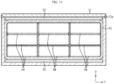
FIGS. 9 and10 , the fatigue failure verification device according to Fourth Embodiment of the present disclosure includes a plurality of mainflexible tubes 34, and the plurality of mainflexible tubes 34 are stacked in the longitudinal direction and the width direction of thebattery cell 20 in the mainflexible tube frame 40. In this case, thepump 35 may individually control the amount of a fluid supplied to each mainflexible tube 34. Accordingly, the plurality of mainflexible tubes 34 may press with different forces according to positions in the longitudinal direction and the width direction of thebattery cell 20. Actually, the degree of volume expansion due to swelling may vary according to positions in the longitudinal direction and the width direction of thebattery cell 20 during swelling of thebattery cell 20. Because the fatigue failure verification device according to Fourth Embodiment of the present disclosure may allow the plurality of mainflexible tubes 34 to press thebattery cell 20 with different forces, an environment similar to an actual swelling environment may be created. - Although the embodiments of the present disclosure have been illustrated and described above, the present disclosure is not limited to the above-described specific embodiments. Various modified embodiments may be made by one of ordinary skill in the art without departing from the scope of the present disclosure as claimed in the claims.
Claims (10)
- A fatigue failure verification device comprising:a module housing comprising a welding portion;a cell stack comprising a plurality of battery cells accommodated in the module housing;at least one main flexible tube located in a central portion of the cell stack in a stack direction of the cell stack;a main flexible tube frame in which the main flexible tube is accommodated, the main flexible tube frame comprising a pair of opening portions formed on both sides so that the main flexible tube faces the battery cell; anda pump configured to adjust a pressure applied by the main flexible tube to the battery cell by supplying a fluid to the main flexible tube.
- The fatigue failure verification device of claim 1, further comprising a pair of sub-flexible tubs respectively located between an upper plate of the module housing and the cell stack and between the upper plate of the module housing and the main flexible tube frame, and between a lower plate of the module housing and the cell stack and between the lower plate of the module housing and the main flexible tube frame.
- The fatigue failure verification device of claim 2, wherein the pump is configured to individually control an amount of a fluid supplied to the main flexible tube and the sub-flexible tubes.
- The fatigue failure verification device of claim 1, wherein the fatigue failure verification device is located between a pair of support walls,
wherein the fatigue failure verification device further comprises a plurality of displacement sensors respectively located between a side of the module housing in a longitudinal direction of the module housing and the support wall and between the other side of the module housing in the longitudinal direction of the module housing and the support wall. - The fatigue failure verification device of claim 1, further comprising a pair of buffer pads respectively provided on both outermost sides of the cell stack in the stack direction of the cell stack.
- The fatigue failure verification device of claim 1, wherein a plurality of main flexible tubes are provided,
wherein the plurality of main flexible tubes are stacked in a width direction of the battery cell in the main flexible tube frame. - The fatigue failure verification device of claim 1, wherein a plurality of main flexible tubes are provided,
wherein the plurality of main flexible tubes are stacked in a longitudinal direction of the battery cell in the main flexible tube frame. - The fatigue failure verification device of claim 1, wherein a plurality of main flexible tubes are provided,
wherein the plurality of main flexible tubes are stacked in a width direction and a longitudinal direction of the battery cell in the main flexible tube frame. - The fatigue failure verification device of any of claims 6 through 8, wherein the pump is configured to individually control an amount of a fluid supplied to the plurality of main flexible tubes.
- The fatigue failure verification device of claim 9, further comprising a pair of sub-flexible tubes respectively located between an upper plate and a lower plate of the module housing and the cell stack, and between the upper plate and the lower plate of the module housing and the main flexible tube frame,
wherein the pump is configured to individually control an amount of a fluid supplied to the plurality of main flexible tubes and the pair of sub-flexible tubes.
Applications Claiming Priority (2)
| Application Number | Priority Date | Filing Date | Title |
|---|---|---|---|
| KR1020200149662A KR20220063611A (en) | 2020-11-10 | 2020-11-10 | Fatigue damage verification device for the welding part of the housing of the battery module |
| PCT/KR2021/016282 WO2022103132A1 (en) | 2020-11-10 | 2021-11-09 | Apparatus for inspecting fatigue fracture of housing welding part of battery module |
Publications (2)
| Publication Number | Publication Date |
|---|---|
| EP4151982A1 true EP4151982A1 (en) | 2023-03-22 |
| EP4151982A4 EP4151982A4 (en) | 2023-12-20 |
Family
ID=81602543
Family Applications (1)
| Application Number | Title | Priority Date | Filing Date |
|---|---|---|---|
| EP21892299.5A Pending EP4151982A4 (en) | 2020-11-10 | 2021-11-09 | Apparatus for inspecting fatigue fracture of housing welding part of battery module |
Country Status (6)
| Country | Link |
|---|---|
| US (1) | US20230375449A1 (en) |
| EP (1) | EP4151982A4 (en) |
| JP (1) | JP2023534471A (en) |
| KR (1) | KR20220063611A (en) |
| CN (1) | CN115698669A (en) |
| WO (1) | WO2022103132A1 (en) |
Family Cites Families (9)
| Publication number | Priority date | Publication date | Assignee | Title |
|---|---|---|---|---|
| KR101108564B1 (en) * | 2009-11-02 | 2012-01-30 | 한국표준과학연구원 | Pressure-Resistant Test Device and Pressure-Resistant Test Method |
| JP2012114030A (en) * | 2010-11-26 | 2012-06-14 | Valeo Japan Co Ltd | Battery temperature adjustment device |
| KR102501672B1 (en) * | 2014-08-29 | 2023-02-17 | 더 리젠츠 오브 더 유니버시티 오브 미시건 | Bulk force in a battery pack and its application to state of charge estimation |
| CN204255553U (en) * | 2014-12-08 | 2015-04-08 | 宁德新能源科技有限公司 | The cell expansion force test device of battery modules |
| KR102308635B1 (en) * | 2015-04-17 | 2021-10-05 | 삼성에스디아이 주식회사 | Battery module |
| JP2018106930A (en) * | 2016-12-27 | 2018-07-05 | 日産自動車株式会社 | Manufacturing method of battery cell and pressure magazine |
| KR102357026B1 (en) * | 2017-06-14 | 2022-01-28 | 에스케이온 주식회사 | Test Device for Battery Cell |
| US11923516B2 (en) * | 2017-07-21 | 2024-03-05 | Quantumscape Battery, Inc. | Active and passive battery pressure management |
| KR102106451B1 (en) * | 2018-06-18 | 2020-05-07 | 비씨에스테크놀러지 주식회사 | Multiaxial test apparatus for battery crush and penetration test |
-
2020
- 2020-11-10 KR KR1020200149662A patent/KR20220063611A/en active Search and Examination
-
2021
- 2021-11-09 JP JP2023502839A patent/JP2023534471A/en active Pending
- 2021-11-09 CN CN202180039955.6A patent/CN115698669A/en active Pending
- 2021-11-09 US US18/031,423 patent/US20230375449A1/en active Pending
- 2021-11-09 WO PCT/KR2021/016282 patent/WO2022103132A1/en active Application Filing
- 2021-11-09 EP EP21892299.5A patent/EP4151982A4/en active Pending
Also Published As
| Publication number | Publication date |
|---|---|
| EP4151982A4 (en) | 2023-12-20 |
| KR20220063611A (en) | 2022-05-17 |
| JP2023534471A (en) | 2023-08-09 |
| CN115698669A (en) | 2023-02-03 |
| US20230375449A1 (en) | 2023-11-23 |
| WO2022103132A1 (en) | 2022-05-19 |
Similar Documents
| Publication | Publication Date | Title |
|---|---|---|
| JP6994674B2 (en) | Power storage device | |
| US11482763B2 (en) | Device for charging and discharging secondary battery | |
| EP3343668A1 (en) | End plate assembly of battery module and battery module | |
| KR101962526B1 (en) | Pressurization device for battery cells | |
| EP3836248A1 (en) | Battery module including foldable side plate and method for manufacturing same | |
| CN110311068A (en) | Battery pack | |
| JP5636634B2 (en) | Electrode plate pressurizing device | |
| KR102476002B1 (en) | Apparatus for measuring thickness of bettery cell | |
| KR102324264B1 (en) | A pressing jig apparatus that closely contacts electrode lead with bus bar and a battery module manufacturing system comprising the same | |
| JP2008535175A (en) | Sealed battery casing | |
| JP6644230B1 (en) | Charge / discharge tester | |
| KR20110137740A (en) | Pressurizing apparatus of laminate type battery | |
| EP3352244A1 (en) | Battery module comprising end plates having improved strucutre, and end plate member therefor | |
| EP4151982A1 (en) | Apparatus for inspecting fatigue fracture of housing welding part of battery module | |
| US20150086900A1 (en) | Fuel cell stack assembly | |
| JP2017027673A (en) | Battery module | |
| JP6463471B2 (en) | Battery case, battery module, and battery module manufacturing method | |
| JP2009004254A (en) | Assembly method of fuel cell stack | |
| JP2024519456A (en) | Battery module housing for a battery module, battery module, and electrical energy storage unit | |
| CN112331935A (en) | Vehicle battery module, vehicle and method for manufacturing vehicle battery module | |
| KR20220040931A (en) | Battery cell pressurizing jig comprising load cell, and pressing method and swelling measurement method for battery cell using ths same | |
| CN219348031U (en) | Clamp and expansion force testing device | |
| JP2019185929A (en) | Manufacturing method of battery module and mechanical characteristic measuring apparatus | |
| EP4071870A1 (en) | Battery cell pressurization jig comprising pressurization pad, and battery cell de-gassing method using same | |
| EP4095978A1 (en) | Charging and discharging apparatus comprising spacers for supporting gas pockets of battery cells |
Legal Events
| Date | Code | Title | Description |
|---|---|---|---|
| STAA | Information on the status of an ep patent application or granted ep patent |
Free format text: STATUS: THE INTERNATIONAL PUBLICATION HAS BEEN MADE |
|
| PUAI | Public reference made under article 153(3) epc to a published international application that has entered the european phase |
Free format text: ORIGINAL CODE: 0009012 |
|
| STAA | Information on the status of an ep patent application or granted ep patent |
Free format text: STATUS: REQUEST FOR EXAMINATION WAS MADE |
|
| 17P | Request for examination filed |
Effective date: 20221215 |
|
| AK | Designated contracting states |
Kind code of ref document: A1 Designated state(s): AL AT BE BG CH CY CZ DE DK EE ES FI FR GB GR HR HU IE IS IT LI LT LU LV MC MK MT NL NO PL PT RO RS SE SI SK SM TR |
|
| REG | Reference to a national code |
Ref country code: DE Ref legal event code: R079 Free format text: PREVIOUS MAIN CLASS: G01N0003100000 Ipc: G01M0005000000 |
|
| A4 | Supplementary search report drawn up and despatched |
Effective date: 20231122 |
|
| RIC1 | Information provided on ipc code assigned before grant |
Ipc: G01N 3/10 20060101ALI20231116BHEP Ipc: G01M 5/00 20060101AFI20231116BHEP |
|
| DAV | Request for validation of the european patent (deleted) | ||
| DAX | Request for extension of the european patent (deleted) |