JP2018106930A - Manufacturing method of battery cell and pressure magazine - Google Patents
Manufacturing method of battery cell and pressure magazine Download PDFInfo
- Publication number
- JP2018106930A JP2018106930A JP2016252370A JP2016252370A JP2018106930A JP 2018106930 A JP2018106930 A JP 2018106930A JP 2016252370 A JP2016252370 A JP 2016252370A JP 2016252370 A JP2016252370 A JP 2016252370A JP 2018106930 A JP2018106930 A JP 2018106930A
- Authority
- JP
- Japan
- Prior art keywords
- battery cell
- pressure
- thickness direction
- spacer
- magazine
- Prior art date
- Legal status (The legal status is an assumption and is not a legal conclusion. Google has not performed a legal analysis and makes no representation as to the accuracy of the status listed.)
- Pending
Links
Images

Classifications
-
- Y—GENERAL TAGGING OF NEW TECHNOLOGICAL DEVELOPMENTS; GENERAL TAGGING OF CROSS-SECTIONAL TECHNOLOGIES SPANNING OVER SEVERAL SECTIONS OF THE IPC; TECHNICAL SUBJECTS COVERED BY FORMER USPC CROSS-REFERENCE ART COLLECTIONS [XRACs] AND DIGESTS
- Y02—TECHNOLOGIES OR APPLICATIONS FOR MITIGATION OR ADAPTATION AGAINST CLIMATE CHANGE
- Y02E—REDUCTION OF GREENHOUSE GAS [GHG] EMISSIONS, RELATED TO ENERGY GENERATION, TRANSMISSION OR DISTRIBUTION
- Y02E60/00—Enabling technologies; Technologies with a potential or indirect contribution to GHG emissions mitigation
- Y02E60/10—Energy storage using batteries
-
- Y—GENERAL TAGGING OF NEW TECHNOLOGICAL DEVELOPMENTS; GENERAL TAGGING OF CROSS-SECTIONAL TECHNOLOGIES SPANNING OVER SEVERAL SECTIONS OF THE IPC; TECHNICAL SUBJECTS COVERED BY FORMER USPC CROSS-REFERENCE ART COLLECTIONS [XRACs] AND DIGESTS
- Y02—TECHNOLOGIES OR APPLICATIONS FOR MITIGATION OR ADAPTATION AGAINST CLIMATE CHANGE
- Y02P—CLIMATE CHANGE MITIGATION TECHNOLOGIES IN THE PRODUCTION OR PROCESSING OF GOODS
- Y02P70/00—Climate change mitigation technologies in the production process for final industrial or consumer products
- Y02P70/50—Manufacturing or production processes characterised by the final manufactured product
Abstract
Description
本発明は、厚さ方向に薄肉な偏平形状をなすバッテリセルを厚さ方向に加圧しつつ初充電を行う、バッテリセルの製造方法および加圧マガジンに関する。 The present invention relates to a battery cell manufacturing method and a pressure magazine that perform initial charging while pressurizing a thin battery cell in the thickness direction in the thickness direction.
ラミネートフィルムからなる外装体の内部に発電要素等を収容してなる偏平な電池を製造する方法の一例として、特許文献1に記載のものが挙げられる。この電池の製造方法の1つの工程である初充電工程では、加圧装置の2枚の加圧板の間に厚さ方向に薄肉な偏平形状をなす電池を配置し、これらの加圧板によって電池の両面側から厚さ方向に電池を加圧した状態で、電池の初充電が行われる。
As an example of a method for manufacturing a flat battery in which a power generation element or the like is accommodated inside an exterior body made of a laminate film, the one described in
しかし、電池の初充電中は、電池が厚さ方向に膨張し、2枚の加圧板から電池に加わえられる加圧力が不必要に上昇する虞がある。 However, during the initial charging of the battery, the battery expands in the thickness direction, and the applied pressure applied to the battery from the two pressure plates may increase unnecessarily.
本発明では、流体圧式の加圧マガジンを用いて、隣接する2つのスペーサの間で各々のバッテリセルが加圧された状態で初充電を行い、この初充電中に、バッテリセルの膨張に対してスペーサ内の流体圧力を一定に保つように、スペーサ内の作動流体の一部を外部に逃がす。 In the present invention, using a fluid pressure type pressurizing magazine, initial charging is performed in a state where each battery cell is pressurized between two adjacent spacers. In order to keep the fluid pressure in the spacer constant, a part of the working fluid in the spacer is released to the outside.
従って、初充電中のバッテリセルの厚さ方向への膨張に伴って、スペーサが厚さ方向に適度に収縮する。 Therefore, as the battery cell during initial charging expands in the thickness direction, the spacer contracts appropriately in the thickness direction.
本発明によれば、初充電中にバッテリセルが厚さ方向に膨張しても、スペーサの収縮によって、一定の加圧力でバッテリセルを加圧した状態を維持することができる。 According to the present invention, even when the battery cell expands in the thickness direction during initial charging, the state in which the battery cell is pressurized with a constant applied pressure can be maintained by contraction of the spacer.
以下、図面を参照しながら本発明の一実施例について説明する。 Hereinafter, an embodiment of the present invention will be described with reference to the drawings.
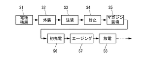
図1は、一実施例のバッテリセル1の製造方法の要部を示した工程説明図である。バッテリセル1(図2参照)は、詳細には図示しないが、例えばリチウムイオン二次電池であり、偏平な長方形の外観形状を有しており、長手方向の一方の端縁に、導電性金属箔からなる薄板状の一対の端子を備えている。このバッテリセル1は、いわゆるフィルム外装電池として、長方形をなす発電要素(電極積層体)を電解液とともにラミネートフィルムからなる外装体の内部に収容したものである。発電要素は、セパレータを介して交互に積層された複数の正極および負極から構成されている。
FIG. 1 is a process explanatory view showing a main part of a method of manufacturing a
ステップS1として示す工程は、発電要素を構成する電極積層工程である。ここでは、それぞれロール状に巻回されている正極、負極およびセパレータを、矩形のシート状に切断しながら順次積層することで、複数の正極および負極がセパレータを介して積層された発電要素つまり電極積層体を形成する。正極は、集電体となるアルミニウム箔の両面に正極活物質をバインダを含むスラリとして塗布し、乾燥かつ圧延して所定の厚みの活物質層を形成したものである。負極は、同様に、集電体となる銅箔の両面に負極活物質をバインダを含むスラリとして塗布し、乾燥かつ圧延して所定の厚みの活物質層を形成したものである。また、セパレータは、正極と負極との間の短絡を防止すると同時に電解液を保持する機能を有するものであって、例えば、ポリエチレン(PE)やポリプロピレン(PP)等の合成樹脂の微多孔性膜あるいは不織布からなる。 The process shown as step S1 is an electrode lamination process which constitutes a power generation element. Here, a positive electrode, a negative electrode, and a separator wound in a roll shape are sequentially stacked while being cut into a rectangular sheet, so that a plurality of positive electrodes and negative electrodes are stacked through separators, that is, an electrode A laminate is formed. The positive electrode is obtained by applying a positive electrode active material as a slurry containing a binder to both surfaces of an aluminum foil serving as a current collector, and drying and rolling to form an active material layer having a predetermined thickness. Similarly, the negative electrode is obtained by applying a negative electrode active material as a slurry containing a binder to both surfaces of a copper foil serving as a current collector, and drying and rolling to form an active material layer having a predetermined thickness. The separator has a function of preventing a short circuit between the positive electrode and the negative electrode and at the same time holding the electrolytic solution. For example, the separator is a microporous film of a synthetic resin such as polyethylene (PE) or polypropylene (PP). Or it consists of a nonwoven fabric.
これらの正極、負極およびセパレータは、所定枚数積層された状態で、発電要素つまり電極積層体となる。複数の正極の集電体の端部は、互いに重ねられ、端子となる正極タブが超音波溶接される。同様に、複数の負極の集電体の端部は、互いに重ねられ、端子となる負極タブが超音波溶接される。 The positive electrode, the negative electrode, and the separator form a power generation element, that is, an electrode laminate in a state where a predetermined number of layers are laminated. The ends of the current collectors of the plurality of positive electrodes are overlapped with each other, and the positive electrode tabs serving as terminals are ultrasonically welded. Similarly, the ends of the current collectors of the plurality of negative electrodes are overlapped with each other, and the negative electrode tabs serving as terminals are ultrasonically welded.
このように構成された発電要素は、次のステップS2として示す外装工程において、可撓性を有するフィルム状外装体の中に配置される。外装体は、例えば、アルミニウム箔の内側に合成樹脂製の熱融着層を、外側に合成樹脂製の保護層をそれぞれラミネートしてなる三層構造を有するラミネートフィルムからなる。一つの例では、外装体は、発電要素の下面側に配置される1枚のラミネートフィルムと上面側に配置される他の1枚のラミネートフィルムとの2枚構造をなし、これら2枚のラミネートフィルムの間に発電要素を配置した上で、周囲の四辺を一辺の注入口を残して重ね合わせ、かつ互いに熱融着してある。従って、外装体は、注入口が開いた袋状の構成となっている。 The power generation element configured as described above is placed in a flexible film-shaped exterior body in an exterior process shown as the next step S2. The exterior body is made of, for example, a laminate film having a three-layer structure in which a synthetic resin heat-sealing layer is laminated on the inner side of an aluminum foil and a synthetic resin protective layer is laminated on the outer side. In one example, the exterior body has a two-sheet structure of one laminate film disposed on the lower surface side of the power generation element and another laminate film disposed on the upper surface side. The power generation element is arranged between the films, and the surrounding four sides are overlapped with each other leaving an injection port, and are heat-sealed to each other. Therefore, the exterior body has a bag-like configuration with an open inlet.
他の一つの例では、1枚の比較的大きなラミネートフィルムを二つ折りにし、2片の間に発電要素を挟み込んだ形に外装体が構成される。この場合は、三辺を一辺の注入口を残して熱融着することとなる。 In another example, the exterior body is configured in such a manner that a relatively large laminate film is folded in two and a power generation element is sandwiched between the two pieces. In this case, the three sides are heat-sealed leaving one side of the inlet.
なお、正極タブおよび負極タブは、注入口を具備する一辺を上方へ向けたときに側方へ向かう辺に位置し、ラミネートフィルムの接合面から外側へ引き出されている。 In addition, the positive electrode tab and the negative electrode tab are located on a side that is directed to the side when one side having the injection port is directed upward, and is drawn outward from the bonding surface of the laminate film.
このように外装工程においてフィルム状外装体の中に発電要素が収容された状態に構成されたバッテリセル1は、次に、ステップS3として示す注液工程に搬送される。注液工程では、例えば減圧チャンバ内にバッテリセル1を立てた状態に配置し、所定の減圧下で外装体の注入口にディスペンサの注液ノズルを差し入れて、電解液の充填(注液)を行う。この注液は、時間間隔を空けて所定量ずつ複数回(例えば7回程度)に分けて行う。つまり、外装体の内部(発電要素の内部を含む)に残存する空気を除去するように減圧状態とした上で、複数回に分けて十分な時間間隔を空けて少量ずつ注入することで、効果的な気液置換を図っている。
Thus, the
注液が完了したら、バッテリセル1の姿勢をそのまま保った状態で、封止工程(ステップS4)として、注入口を熱融着により封止する。なお、ここでの封止はいわゆる仮封止であり、後述する充電後に、充電に伴って発生したガス抜きのために注入口(あるいはその近傍)が開封されるので、ガス抜き後に、最終的な封止を行うこととなる。封止後には、厚さ方向に薄肉な偏平形状をなすバッテリセル1が形成される。
When the liquid injection is completed, the inlet is sealed by heat sealing as a sealing step (step S4) while maintaining the posture of the
ステップS4の封止工程の次に、ステップS5として示すマガジン装填工程において、ロボットハンド等により減圧チャンバからバッテリセル1を取り出して、バッテリセル1の正極タブおよび負極タブが横向きとなったまま、後述する加圧マガジン2に装填する。1つの加圧マガジン2には、複数個のバッテリセル1が該バッテリセル1の厚さ方向に沿って積層された形に収容される。
In the magazine loading step shown as step S5 after the sealing step in step S4, the
そして、ステップS6の初充電工程において、バッテリセル1の初充電を行う。この初充電は、複数の正極および負極を含む発電要素における電極間の間隔を一定に得るために、加圧マガジン2内において、バッテリセル1を厚さ方向Pに沿って適宜に加圧した状態で行う。
And in the initial charge process of step S6, the
ステップS6の初充電工程の次に、ステップS7として示すエージング工程において、初充電後のバッテリセル1を所定の温度で一定期間放置する。このエージング工程は、加圧マガジン2内において、バッテリセル1を厚さ方向Pに沿って適宜に加圧した状態で行う。
Following the initial charging process of step S6, in the aging process shown as step S7, the
そして、ステップS8の放電工程において、バッテリセル1の容量を測定するために、バッテリセル1の放電を行う。この放電は、バッテリセル1の収縮によりバッテリセル1のラミネートフィルムにしわが生じることを抑制するために、やはり加圧マガジン2内において、バッテリセル1を厚さ方向Pに沿って適宜に加圧した状態で行う。
And in the discharge process of step S8, in order to measure the capacity | capacitance of the
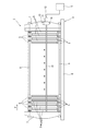
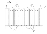
次に、図2を参照することにより、加圧マガジン2について説明する。この加圧マガジン2は、複数のバッテリセル1を収容するハウジング4と、バッテリセル1の厚さ方向(図中の矢印P方向)に関して所定の等間隔置きにハウジング4に支持され、内部に封入される作動流体としてのエアのエア圧力(流体圧力)に応じて、バッテリセル1の厚さ方向Pに膨張する複数のスペーサ3と、を備えている。そして、複数のスペーサ3内にエア圧力を供給する流体圧力源として、ハウジング4の外部にエア機器5を備えている。
Next, the pressurizing
ハウジング4は、コンベアで搬送するための平坦な矩形の板状をなすベースプレート6と、このベースプレート6の長手方向の両端部に立設された一対の固定プレート7と、を有しており、これら一対の固定プレート7の間に、複数のスペーサ3が、所定の間隔置きに配置されている。
The housing 4 includes a
固定プレート7は、複数のバッテリセル1が加圧されたときにその全体の荷重を受けるもので、比較的に厚肉であり、ベースプレート6に強固に固定されている。
The fixed
固定プレート7の四隅には、両固定プレート7の間に架け渡されたガイドシャフト8が固定されており、これら4本のガイドシャフト8によって各スペーサ3が厚さ方向Pに摺動可能に支持されている。このガイドシャフト8には、隣り合うスペーサ3間のピッチを一定とするように円筒状のブッシュ9が各スペーサ3の間に挿入されている。つまり、ガイドシャフト8上にブッシュ9とスペーサ3とが互いに接触する状態で交互に配置されており、その全体が両側の固定プレート7により挟持されている。これにより、一対の固定プレート7の間で複数のスペーサ3が等間隔置きに配置されている。
Guide shafts 8 spanned between the two fixed
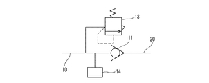
また、ハウジング4の側部には、圧力供給通路として、ガイドシャフト8と平行に延びたエア配管10が配置されており、このエア配管10によって、エア機器5から各スペーサ3にエアが供給されるようになっている。エア配管10の基端には、スペーサ3に導入されたエアの逆流を防止する逆止弁11が設けられており、逆止弁11のエア入口20(図3,4参照)に着脱可能に接続されるジョイント12を介して、エア配管10がエア機器5に接続される。
In addition, an
逆止弁11は、図3に示すように、スペーサ3内のエアの一部を逃がすリリーフバルブ13に並列に接続されている。リリーフバルブ13は、所定の設定圧で機械的に開弁し、スペーサ3内のエアの一部を外部に逃がすように構成されている。また、図3に示すように、エア配管10の逆止弁11付近には、スペーサ3内のエア圧力(加圧力)を検出するエア圧センサ14が設けられている。リリーフバルブ13およびエア圧センサ14は、図2には図示されていないが、加圧マガジン2に一体に設けられている。
As shown in FIG. 3, the
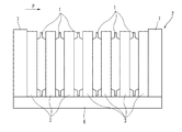
上記のような加圧マガジン2は、例えばバッテリセル1への初充電、その後のエージングおよびバッテリセル1からの放電に際してのバッテリセル1の加圧のために用いられる。ハウジング4へのバッテリセル1の挿入は、個々のスペーサ3を収縮させたままの状態で行われる。図2に示すように、隣接する2つのスペーサ3の間にそれぞれバッテリセル1が挿入され、これにより、各スペーサ3は個々のバッテリセル1の間に位置した状態となる。スペーサ3が収縮することで2つのスペーサ3の間に十分に大きい隙間が確保されるので、ロボットハンド等によりバッテリセル1を容易に挿入することができる。
The pressurizing
なお、本実施例の加圧マガジン2は、国際公開第2015/141631号に記載のものと基本的に同様の構成を有している。
In addition, the
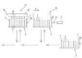
図4は、加圧マガジン2を用いた初充電工程S6をより詳しく示した説明図である。複数のバッテリセル1を装填した状態の加圧マガジン2(図4の右側の加圧マガジン2)は、図示せぬコンベアおよびリフト機構を用いて、加圧ステージ15に移送される。そして、この加圧ステージ15において、加圧マガジン2に設けられた逆止弁11のエア入口20に、ジョイント12を介してエア機器5が接続される。このエア機器5によって各スペーサ3に加圧エアを供給することにより、各スペーサ3が膨張する。これによって、隣り合う2つのスペーサ3の間に配置されたバッテリセル1が厚さ方向Pに加圧される。スペーサ3の内圧が所定の圧力となったら、エア機器5を停止し、ジョイント12が、逆止弁11から取り外される。ジョイント12を取り外した後も、逆止弁11によって所定の加圧状態が保持される。このスペーサ3内のエア圧力は、バッテリセル1が、バッテリセル1の発電要素のSEI(Solid Electrolyte Interface)被膜の形成に適した加圧力で加圧されるように設定されている。このエア圧力は、例えば約0.49×10⁻²MPa(0.05Kgf/cm2)〜約24.5×10-2MPa(2.5Kgf/cm2)の範囲内の適当な圧力に設定されている。
FIG. 4 is an explanatory diagram showing the initial charging step S6 using the
ジョイント12の取り外し後、加圧マガジン2は、図示せぬコンベアおよびリフト機構を用いて、図4に示すように、チャック機構16を有した初充電ステージ17に移送される。
After the joint 12 is removed, the
このチャック機構16は、図示せぬ駆動機構によって加圧マガジン2に向かって進退する基部18と、この基部18に取り付けられ、バッテリセル1の正極タブまたは負極タブを挟持するクリップ状の複数のチャック部19と、を備えている。各々のチャック部19は、図示せぬ充電ユニットに電気的に接続されている。
The
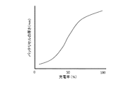
初充電ステージ17では、各チャック部19がバッテリセル1の正極タブまたは負極タブを挟持した状態で、図示せぬ充電ユニットにより、加圧マガジン2毎に複数のバッテリセル1の初充電が行われる。ここで、初充電が進行するにつれて、バッテリセル1は、厚さ方向Pに膨張する。つまり、初充電中におけるバッテリセル1の充電率(SOC)の増加に伴って、バッテリセル1の厚さが大きくなる。初充電におけるバッテリセル1の充電率(SOC)とバッテリセル1の厚さとの相関関係は、例えば、図5に示すグラフのようになる。
In the
仮に、本実施例において加圧マガジン2がリリーフバルブ13を具備していない場合は、初充電中におけるバッテリセル1の厚さ方向Pへの膨張に伴って、スペーサ3からバッテリセル1に加わる加圧力が不必要に上昇する虞がある。
If the pressurizing
よって、本実施例では、リリーフバルブ13の機械的な開放により、図6に示すように初充電中のバッテリセル1の厚さ方向Pへの膨張に伴ってスペーサ3を厚さ方向Pに収縮させることで、バッテリセル1の膨張に対してスペーサ3内のエア圧力を一定に保つようにしてある。従って、初充電中にバッテリセル1が厚さ方向Pに膨張しても、スペーサ3によって一定の加圧力でバッテリセル1を加圧した状態を維持することができる。
Therefore, in this embodiment, the relief of the
なお、上記のように初充電中に一定の加圧力を維持することで、加圧マガジン2の固定プレート7にかかる荷重が過度に上昇しないから、固定プレート7の強度に過度に余裕を与えることがない。
In addition, since the load applied to the fixed
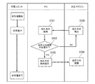
次に、図7を参照することにより、第2の実施例のバッテリセル1の製造方法について説明する。第2の実施例に用いられる加圧マガジン2は、第1の実施例の加圧マガジン2(図2参照)のリリーフバルブ13および逆止弁11に代えて、電磁弁51を備えている。さらに、この電磁弁51と、エア圧センサ14とが、プログラマブルロジックコントローラ(PLC)52に接続されている。電磁弁51は、エア圧センサ14によって検出されたエア圧力に基づいて開弁するように構成されている。
Next, a method for manufacturing the
図8のフローチャートに示すように、ステップS100において、バッテリセル1の初充電中に、エア圧センサ14によってスペーサ3内のエア圧力つまりスペーサ3によるバッテリセル1への加圧力が検出される。そして、ステップS101において、PLC52が、エア圧センサ14により検出された加圧力を取得する。次に、ステップS102において、加圧力の調整が必要であるか否かについて判断する。この判断は、取得された加圧力が、上述したSEI被膜の形成に適した加圧力(スペーサ3内のエア圧力)と一致するか否かによって行われる。加圧力の調整が必要でない、即ち取得された加圧力が上記加圧力(スペーサ3内のエア圧力)と一致する場合には、ステップS100において、加圧力の検出を継続する。
As shown in the flowchart of FIG. 8, in step S100, during the initial charging of the
一方、加圧力の調整が必要である、即ち取得された加圧力が上記加圧力(スペーサ3内のエア圧力)を越えている場合には、ステップS103において、加圧力の制御を指示し、そして、ステップS104において、加圧力を調整する。この調整は、加圧力が上記加圧力(スペーサ3内のエア圧力)と一致するように、エア配管10に設けられた電磁弁51を開弁することで行われる。
On the other hand, if it is necessary to adjust the applied pressure, that is, if the acquired applied pressure exceeds the applied pressure (the air pressure in the spacer 3), the control of the applied pressure is instructed in step S103, and In step S104, the pressure is adjusted. This adjustment is performed by opening the electromagnetic valve 51 provided in the
従って、第2の実施例においても、バッテリセル1の初充電中に、一定の加圧力でバッテリセル1を加圧した状態が維持される。
Accordingly, also in the second embodiment, the state in which the
なお、第1および第2の実施例における初充電中のバッテリセル1の加圧は、負極にシリコンを含む比較的膨張し易い形式のバッテリセルに対して特に好適である。
Note that the pressurization of the
次に、バッテリセル1の放電中のスペーサ3によるバッテリセル1への加圧力の制御について説明する。この放電中の加圧力の制御は、第1の実施例または第2の実施例の加圧マガジン2を用い、エア配管10がエア機器5に接続された状態で行われる。
Next, control of the pressure applied to the
バッテリセル1の放電中は、放電が進行するにつれて、バッテリセル1が厚さ方向Pに収縮する。放電中にバッテリセル1が収縮すると、スペーサ3内のエア圧力が低下してバッテリセル1とスペーサ3との間に隙間が生じるため、バッテリセル1のラミネートフィルムにしわが発生する虞がある。
During the discharge of the
そこで、この実施例では、エア機器5からのエアの追加的な供給により、図9に示すように放電中のバッテリセル1の厚さ方向Pへの収縮に対しスペーサ3内のエア圧力を一定に保つことで、バッテリセル1とスペーサ3とが常に密着した状態でスペーサ3が一定の加圧力でバッテリセル1を加圧するようにしてある。具体的には、放電中のバッテリセル1の厚さ方向Pへの収縮に対してスペーサ3内のエア圧力を一定に保つように、バッテリセル1の収縮に伴ってエア機器5から逆止弁11または電磁弁51を介してスペーサ3内にエアを適宜供給するようにしている。このとき、放電中のエアの供給は、エア圧センサ14で検出された圧力に基づいて行われる。
Therefore, in this embodiment, the additional air supply from the
従って、本実施例では、バッテリセル1が厚さ方向Pに収縮する放電中に、スペーサ3が一定の加圧力でバッテリセル1を加圧することで、バッテリセル1のラミネートフィルムへのしわの発生が抑制される。
Accordingly, in this embodiment, during the discharge in which the
1・・・バッテリセル
2・・・加圧マガジン
3・・・スペーサ
4・・・ハウジング
5・・・エア機器
7・・・固定プレート
11・・・逆止弁
13・・・リリーフバルブ
14・・・エア圧センサ
16・・・チャック機構
51・・・電磁弁
52・・・プログラマブルロジックコントローラ(PLC)
DESCRIPTION OF
Claims (5)
前記バッテリセルの初充電は、内部に封入される作動流体の流体圧力に応じて前記厚さ方向に膨張する複数のスペーサを有した加圧マガジンを用いて、隣接する2つのスペーサの間に各々のバッテリセルを配置して行われ、
前記初充電中に、前記バッテリセルの膨張に対して前記スペーサ内の流体圧力を一定に保つように、前記スペーサ内の作動流体の一部を外部に逃がすことを特徴とするバッテリセルの製造方法。 A battery cell manufacturing method for performing initial charging while pressurizing a thin battery cell in the thickness direction in the thickness direction,
The initial charging of the battery cell is performed between two adjacent spacers using a pressure magazine having a plurality of spacers that expands in the thickness direction according to the fluid pressure of the working fluid sealed inside. Is done by placing battery cells
During the initial charging, a part of the working fluid in the spacer is released to the outside so that the fluid pressure in the spacer is kept constant with respect to the expansion of the battery cell. .
内部に封入される作動流体の流体圧力に応じて前記厚さ方向に膨張し、個々のバッテリセルを挟む複数のスペーサと、
設定圧で機械的に開弁するリリーフバルブと、
を備え、
前記リリーフバルブは、前記初充電中に、前記バッテリセルの膨張に応じて前記スペーサ内の作動流体の一部を外部に逃がすことを特徴とする加圧マガジン。 In the pressurization magazine of the battery cell in which the power generation element is enclosed with the electrolytic solution inside the film-shaped exterior body and a plurality of battery cells having a thin flat shape in the thickness direction are pressurized in the thickness direction during the initial charge,
A plurality of spacers that expand in the thickness direction according to the fluid pressure of the working fluid sealed therein, and sandwich the individual battery cells;
A relief valve that opens mechanically at the set pressure;
With
The pressure magazine, wherein the relief valve releases part of the working fluid in the spacer to the outside according to the expansion of the battery cell during the initial charging.
Priority Applications (1)
| Application Number | Priority Date | Filing Date | Title |
|---|---|---|---|
| JP2016252370A JP2018106930A (en) | 2016-12-27 | 2016-12-27 | Manufacturing method of battery cell and pressure magazine |
Applications Claiming Priority (1)
| Application Number | Priority Date | Filing Date | Title |
|---|---|---|---|
| JP2016252370A JP2018106930A (en) | 2016-12-27 | 2016-12-27 | Manufacturing method of battery cell and pressure magazine |
Publications (1)
| Publication Number | Publication Date |
|---|---|
| JP2018106930A true JP2018106930A (en) | 2018-07-05 |
Family
ID=62788066
Family Applications (1)
| Application Number | Title | Priority Date | Filing Date |
|---|---|---|---|
| JP2016252370A Pending JP2018106930A (en) | 2016-12-27 | 2016-12-27 | Manufacturing method of battery cell and pressure magazine |
Country Status (1)
| Country | Link |
|---|---|
| JP (1) | JP2018106930A (en) |
Cited By (6)
| Publication number | Priority date | Publication date | Assignee | Title |
|---|---|---|---|---|
| WO2021215427A1 (en) * | 2020-04-21 | 2021-10-28 | 株式会社スリーダム | Battery and method for controlling same |
| CN114054610A (en) * | 2021-10-29 | 2022-02-18 | 广东利元亨智能装备股份有限公司 | Pole lug pressing device, pole piece winding equipment and pole lug pressing method |
| WO2022044292A1 (en) | 2020-08-28 | 2022-03-03 | 平田機工株式会社 | Test method and manufacturing method |
| WO2023140708A1 (en) * | 2022-01-21 | 2023-07-27 | 주식회사 엘지에너지솔루션 | Battery module, and manufacturing method therefor |
| EP4151982A4 (en) * | 2020-11-10 | 2023-12-20 | LG Energy Solution, Ltd. | Apparatus for inspecting fatigue fracture of housing welding part of battery module |
| US11959974B2 (en) | 2019-09-18 | 2024-04-16 | Lg Energy Solution, Ltd. | Pressurizing short-circuit inspection apparatus for detecting low-voltage defective pouch-type secondary battery cell |
Citations (4)
| Publication number | Priority date | Publication date | Assignee | Title |
|---|---|---|---|---|
| JPS6012298A (en) * | 1983-07-04 | 1985-01-22 | Kobe Steel Ltd | Pressure regulator in cold hydrostatic pressurizing device |
| JP2003346885A (en) * | 2002-05-27 | 2003-12-05 | Nec Tohoku Ltd | Pressurizing apparatus for charging/discharging secondary battery |
| JP2009295289A (en) * | 2008-06-02 | 2009-12-17 | Panasonic Corp | Lithium-ion secondary battery and method of manufacturing the same |
| WO2015141631A1 (en) * | 2014-03-17 | 2015-09-24 | 日産自動車株式会社 | Pressurization device for battery cells |
-
2016
- 2016-12-27 JP JP2016252370A patent/JP2018106930A/en active Pending
Patent Citations (4)
| Publication number | Priority date | Publication date | Assignee | Title |
|---|---|---|---|---|
| JPS6012298A (en) * | 1983-07-04 | 1985-01-22 | Kobe Steel Ltd | Pressure regulator in cold hydrostatic pressurizing device |
| JP2003346885A (en) * | 2002-05-27 | 2003-12-05 | Nec Tohoku Ltd | Pressurizing apparatus for charging/discharging secondary battery |
| JP2009295289A (en) * | 2008-06-02 | 2009-12-17 | Panasonic Corp | Lithium-ion secondary battery and method of manufacturing the same |
| WO2015141631A1 (en) * | 2014-03-17 | 2015-09-24 | 日産自動車株式会社 | Pressurization device for battery cells |
Cited By (7)
| Publication number | Priority date | Publication date | Assignee | Title |
|---|---|---|---|---|
| US11959974B2 (en) | 2019-09-18 | 2024-04-16 | Lg Energy Solution, Ltd. | Pressurizing short-circuit inspection apparatus for detecting low-voltage defective pouch-type secondary battery cell |
| WO2021215427A1 (en) * | 2020-04-21 | 2021-10-28 | 株式会社スリーダム | Battery and method for controlling same |
| WO2022044292A1 (en) | 2020-08-28 | 2022-03-03 | 平田機工株式会社 | Test method and manufacturing method |
| EP4151982A4 (en) * | 2020-11-10 | 2023-12-20 | LG Energy Solution, Ltd. | Apparatus for inspecting fatigue fracture of housing welding part of battery module |
| CN114054610A (en) * | 2021-10-29 | 2022-02-18 | 广东利元亨智能装备股份有限公司 | Pole lug pressing device, pole piece winding equipment and pole lug pressing method |
| CN114054610B (en) * | 2021-10-29 | 2023-08-22 | 广东利元亨智能装备股份有限公司 | Tab pressing device, pole piece winding equipment and pole tab pressing method |
| WO2023140708A1 (en) * | 2022-01-21 | 2023-07-27 | 주식회사 엘지에너지솔루션 | Battery module, and manufacturing method therefor |
Similar Documents
| Publication | Publication Date | Title |
|---|---|---|
| JP2018106930A (en) | Manufacturing method of battery cell and pressure magazine | |
| US11276903B2 (en) | Electricity storage device and method for manufacturing electricity storage device | |
| JP6578590B2 (en) | Method for producing film-clad battery | |
| JP6039086B2 (en) | Pouch type secondary battery sealing tool | |
| WO2015141631A1 (en) | Pressurization device for battery cells | |
| JP7055305B2 (en) | Pouch-type battery case including crack prevention structure and its manufacturing method | |
| KR101713042B1 (en) | High Temperature Pressing Device for Battery Cell | |
| KR101471765B1 (en) | Sealing method of pouch-type secondary battery, pouch-type secondary battery, and method for manufacturing the same | |
| US11539068B2 (en) | Method for manufacturing secondary battery | |
| US10847779B2 (en) | Film-covered battery production method and film-covered battery | |
| KR102217443B1 (en) | Gas removal device and gas removal method for rechargeable battery | |
| US11870082B2 (en) | Method for manufacturing secondary battery | |
| JP2015156322A (en) | Electric device | |
| JP7123687B2 (en) | BIPOLAR BATTERY AND METHOD OF MANUFACTURING BIPOLAR BATTERY | |
| JP6683089B2 (en) | Power storage device | |
| US20230369630A1 (en) | Unit Cell Preparation Apparatus and Method | |
| JP2019091606A (en) | Manufacturing method of bipolar battery | |
| KR102259747B1 (en) | Electrode assembly and manufacturing method thereof | |
| JP2018120803A (en) | Method for manufacturing film package battery and film package battery | |
| EP3866242A1 (en) | Electrode assembly manufacturing apparatus and electrode assembly manufacturing method | |
| JP7324405B2 (en) | Laminated battery manufacturing method | |
| JP2023554293A (en) | Pressurized channel and secondary battery charging/discharging device including it | |
| KR20180137346A (en) | Degenerate cell regnerative method | |
| JP2020009618A (en) | Power-storage module production method and feeding device | |
| US20230170565A1 (en) | Battery cell sealing apparatus |
Legal Events
| Date | Code | Title | Description |
|---|---|---|---|
| A711 | Notification of change in applicant |
Free format text: JAPANESE INTERMEDIATE CODE: A712 Effective date: 20190528 |
|
| A621 | Written request for application examination |
Free format text: JAPANESE INTERMEDIATE CODE: A621 Effective date: 20190917 |
|
| A977 | Report on retrieval |
Free format text: JAPANESE INTERMEDIATE CODE: A971007 Effective date: 20200630 |
|
| A131 | Notification of reasons for refusal |
Free format text: JAPANESE INTERMEDIATE CODE: A131 Effective date: 20201026 |
|
| A02 | Decision of refusal |
Free format text: JAPANESE INTERMEDIATE CODE: A02 Effective date: 20210525 |