EP4151403A1 - Panneau de plancher multicouche avec noyau élastique - Google Patents
Panneau de plancher multicouche avec noyau élastique Download PDFInfo
- Publication number
- EP4151403A1 EP4151403A1 EP22199550.9A EP22199550A EP4151403A1 EP 4151403 A1 EP4151403 A1 EP 4151403A1 EP 22199550 A EP22199550 A EP 22199550A EP 4151403 A1 EP4151403 A1 EP 4151403A1
- Authority
- EP
- European Patent Office
- Prior art keywords
- layer
- core
- floor panel
- tongue
- groove
- Prior art date
- Legal status (The legal status is an assumption and is not a legal conclusion. Google has not performed a legal analysis and makes no representation as to the accuracy of the status listed.)
- Granted
Links
- 229920003023 plastic Polymers 0.000 claims abstract description 18
- 239000004033 plastic Substances 0.000 claims abstract description 18
- 239000010410 layer Substances 0.000 claims description 172
- 239000012792 core layer Substances 0.000 claims description 72
- 230000002787 reinforcement Effects 0.000 claims description 53
- 239000000463 material Substances 0.000 claims description 51
- 239000004800 polyvinyl chloride Substances 0.000 claims description 45
- 239000003365 glass fiber Substances 0.000 claims description 23
- 229920000915 polyvinyl chloride Polymers 0.000 claims description 18
- 239000000945 filler Substances 0.000 claims description 17
- 238000013016 damping Methods 0.000 claims description 15
- 238000003490 calendering Methods 0.000 claims description 8
- 229920002635 polyurethane Polymers 0.000 claims description 7
- 239000004814 polyurethane Substances 0.000 claims description 7
- 239000012764 mineral filler Substances 0.000 claims description 5
- 238000003825 pressing Methods 0.000 claims description 5
- 239000002023 wood Substances 0.000 claims description 5
- 230000000295 complement effect Effects 0.000 claims description 3
- 229920000098 polyolefin Polymers 0.000 claims description 3
- 239000006260 foam Substances 0.000 claims description 2
- 229920001169 thermoplastic Polymers 0.000 claims description 2
- 239000004416 thermosoftening plastic Substances 0.000 claims 1
- 239000004922 lacquer Substances 0.000 abstract description 13
- 210000002105 tongue Anatomy 0.000 description 67
- 238000000034 method Methods 0.000 description 22
- 230000008569 process Effects 0.000 description 10
- 239000004014 plasticizer Substances 0.000 description 8
- 230000008901 benefit Effects 0.000 description 5
- 238000004519 manufacturing process Methods 0.000 description 5
- GNFTZDOKVXKIBK-UHFFFAOYSA-N 3-(2-methoxyethoxy)benzohydrazide Chemical compound COCCOC1=CC=CC(C(=O)NN)=C1 GNFTZDOKVXKIBK-UHFFFAOYSA-N 0.000 description 4
- 239000007788 liquid Substances 0.000 description 4
- 239000000853 adhesive Substances 0.000 description 3
- 238000004026 adhesive bonding Methods 0.000 description 3
- 230000001070 adhesive effect Effects 0.000 description 3
- 239000006185 dispersion Substances 0.000 description 3
- 238000001125 extrusion Methods 0.000 description 3
- 238000011900 installation process Methods 0.000 description 3
- 238000010030 laminating Methods 0.000 description 3
- 238000005096 rolling process Methods 0.000 description 3
- 239000004576 sand Substances 0.000 description 3
- 239000000758 substrate Substances 0.000 description 3
- 238000005299 abrasion Methods 0.000 description 2
- 230000015572 biosynthetic process Effects 0.000 description 2
- 230000008859 change Effects 0.000 description 2
- 238000005755 formation reaction Methods 0.000 description 2
- 238000004064 recycling Methods 0.000 description 2
- 230000000284 resting effect Effects 0.000 description 2
- 239000004575 stone Substances 0.000 description 2
- XLYOFNOQVPJJNP-UHFFFAOYSA-N water Substances O XLYOFNOQVPJJNP-UHFFFAOYSA-N 0.000 description 2
- 230000009471 action Effects 0.000 description 1
- 239000012790 adhesive layer Substances 0.000 description 1
- 230000032683 aging Effects 0.000 description 1
- 238000013459 approach Methods 0.000 description 1
- 238000005452 bending Methods 0.000 description 1
- 229910000019 calcium carbonate Inorganic materials 0.000 description 1
- -1 chalk Substances 0.000 description 1
- 239000011093 chipboard Substances 0.000 description 1
- 230000006835 compression Effects 0.000 description 1
- 238000007906 compression Methods 0.000 description 1
- 238000010276 construction Methods 0.000 description 1
- 238000011109 contamination Methods 0.000 description 1
- 238000005520 cutting process Methods 0.000 description 1
- 230000006866 deterioration Effects 0.000 description 1
- 238000009792 diffusion process Methods 0.000 description 1
- 238000001035 drying Methods 0.000 description 1
- 230000000694 effects Effects 0.000 description 1
- 239000013013 elastic material Substances 0.000 description 1
- 238000004049 embossing Methods 0.000 description 1
- 238000001704 evaporation Methods 0.000 description 1
- 230000008020 evaporation Effects 0.000 description 1
- 239000004744 fabric Substances 0.000 description 1
- 238000007667 floating Methods 0.000 description 1
- 238000009408 flooring Methods 0.000 description 1
- 239000003292 glue Substances 0.000 description 1
- 238000007373 indentation Methods 0.000 description 1
- 238000003780 insertion Methods 0.000 description 1
- 230000037431 insertion Effects 0.000 description 1
- 239000002650 laminated plastic Substances 0.000 description 1
- 238000003475 lamination Methods 0.000 description 1
- 230000002045 lasting effect Effects 0.000 description 1
- 230000005012 migration Effects 0.000 description 1
- 238000013508 migration Methods 0.000 description 1
- 230000008092 positive effect Effects 0.000 description 1
- 238000007639 printing Methods 0.000 description 1
- 239000002994 raw material Substances 0.000 description 1
- 238000009418 renovation Methods 0.000 description 1
- 230000000630 rising effect Effects 0.000 description 1
- 239000002356 single layer Substances 0.000 description 1
- 239000007787 solid Substances 0.000 description 1
- 238000012546 transfer Methods 0.000 description 1
- 230000003313 weakening effect Effects 0.000 description 1
Images


Classifications
-
- B—PERFORMING OPERATIONS; TRANSPORTING
- B32—LAYERED PRODUCTS
- B32B—LAYERED PRODUCTS, i.e. PRODUCTS BUILT-UP OF STRATA OF FLAT OR NON-FLAT, e.g. CELLULAR OR HONEYCOMB, FORM
- B32B27/00—Layered products comprising a layer of synthetic resin
- B32B27/12—Layered products comprising a layer of synthetic resin next to a fibrous or filamentary layer
-
- B—PERFORMING OPERATIONS; TRANSPORTING
- B32—LAYERED PRODUCTS
- B32B—LAYERED PRODUCTS, i.e. PRODUCTS BUILT-UP OF STRATA OF FLAT OR NON-FLAT, e.g. CELLULAR OR HONEYCOMB, FORM
- B32B27/00—Layered products comprising a layer of synthetic resin
- B32B27/18—Layered products comprising a layer of synthetic resin characterised by the use of special additives
- B32B27/20—Layered products comprising a layer of synthetic resin characterised by the use of special additives using fillers, pigments, thixotroping agents
-
- B—PERFORMING OPERATIONS; TRANSPORTING
- B32—LAYERED PRODUCTS
- B32B—LAYERED PRODUCTS, i.e. PRODUCTS BUILT-UP OF STRATA OF FLAT OR NON-FLAT, e.g. CELLULAR OR HONEYCOMB, FORM
- B32B27/00—Layered products comprising a layer of synthetic resin
- B32B27/30—Layered products comprising a layer of synthetic resin comprising vinyl (co)polymers; comprising acrylic (co)polymers
- B32B27/304—Layered products comprising a layer of synthetic resin comprising vinyl (co)polymers; comprising acrylic (co)polymers comprising vinyl halide (co)polymers, e.g. PVC, PVDC, PVF, PVDF
-
- B—PERFORMING OPERATIONS; TRANSPORTING
- B32—LAYERED PRODUCTS
- B32B—LAYERED PRODUCTS, i.e. PRODUCTS BUILT-UP OF STRATA OF FLAT OR NON-FLAT, e.g. CELLULAR OR HONEYCOMB, FORM
- B32B3/00—Layered products comprising a layer with external or internal discontinuities or unevennesses, or a layer of non-planar shape; Layered products comprising a layer having particular features of form
- B32B3/02—Layered products comprising a layer with external or internal discontinuities or unevennesses, or a layer of non-planar shape; Layered products comprising a layer having particular features of form characterised by features of form at particular places, e.g. in edge regions
- B32B3/06—Layered products comprising a layer with external or internal discontinuities or unevennesses, or a layer of non-planar shape; Layered products comprising a layer having particular features of form characterised by features of form at particular places, e.g. in edge regions for securing layers together; for attaching the product to another member, e.g. to a support, or to another product, e.g. groove/tongue, interlocking
-
- E—FIXED CONSTRUCTIONS
- E04—BUILDING
- E04F—FINISHING WORK ON BUILDINGS, e.g. STAIRS, FLOORS
- E04F15/00—Flooring
- E04F15/02—Flooring or floor layers composed of a number of similar elements
- E04F15/10—Flooring or floor layers composed of a number of similar elements of other materials, e.g. fibrous or chipped materials, organic plastics, magnesite tiles, hardboard, or with a top layer of other materials
-
- B—PERFORMING OPERATIONS; TRANSPORTING
- B32—LAYERED PRODUCTS
- B32B—LAYERED PRODUCTS, i.e. PRODUCTS BUILT-UP OF STRATA OF FLAT OR NON-FLAT, e.g. CELLULAR OR HONEYCOMB, FORM
- B32B2260/00—Layered product comprising an impregnated, embedded, or bonded layer wherein the layer comprises an impregnation, embedding, or binder material
- B32B2260/02—Composition of the impregnated, bonded or embedded layer
- B32B2260/021—Fibrous or filamentary layer
- B32B2260/023—Two or more layers
-
- B—PERFORMING OPERATIONS; TRANSPORTING
- B32—LAYERED PRODUCTS
- B32B—LAYERED PRODUCTS, i.e. PRODUCTS BUILT-UP OF STRATA OF FLAT OR NON-FLAT, e.g. CELLULAR OR HONEYCOMB, FORM
- B32B2260/00—Layered product comprising an impregnated, embedded, or bonded layer wherein the layer comprises an impregnation, embedding, or binder material
- B32B2260/04—Impregnation, embedding, or binder material
- B32B2260/046—Synthetic resin
-
- B—PERFORMING OPERATIONS; TRANSPORTING
- B32—LAYERED PRODUCTS
- B32B—LAYERED PRODUCTS, i.e. PRODUCTS BUILT-UP OF STRATA OF FLAT OR NON-FLAT, e.g. CELLULAR OR HONEYCOMB, FORM
- B32B2262/00—Composition or structural features of fibres which form a fibrous or filamentary layer or are present as additives
- B32B2262/10—Inorganic fibres
- B32B2262/101—Glass fibres
-
- B—PERFORMING OPERATIONS; TRANSPORTING
- B32—LAYERED PRODUCTS
- B32B—LAYERED PRODUCTS, i.e. PRODUCTS BUILT-UP OF STRATA OF FLAT OR NON-FLAT, e.g. CELLULAR OR HONEYCOMB, FORM
- B32B2305/00—Condition, form or state of the layers or laminate
- B32B2305/08—Reinforcements
-
- B—PERFORMING OPERATIONS; TRANSPORTING
- B32—LAYERED PRODUCTS
- B32B—LAYERED PRODUCTS, i.e. PRODUCTS BUILT-UP OF STRATA OF FLAT OR NON-FLAT, e.g. CELLULAR OR HONEYCOMB, FORM
- B32B2307/00—Properties of the layers or laminate
- B32B2307/10—Properties of the layers or laminate having particular acoustical properties
- B32B2307/102—Insulating
-
- B—PERFORMING OPERATIONS; TRANSPORTING
- B32—LAYERED PRODUCTS
- B32B—LAYERED PRODUCTS, i.e. PRODUCTS BUILT-UP OF STRATA OF FLAT OR NON-FLAT, e.g. CELLULAR OR HONEYCOMB, FORM
- B32B2315/00—Other materials containing non-metallic inorganic compounds not provided for in groups B32B2311/00 - B32B2313/04
- B32B2315/08—Glass
- B32B2315/085—Glass fiber cloth or fabric
-
- B—PERFORMING OPERATIONS; TRANSPORTING
- B32—LAYERED PRODUCTS
- B32B—LAYERED PRODUCTS, i.e. PRODUCTS BUILT-UP OF STRATA OF FLAT OR NON-FLAT, e.g. CELLULAR OR HONEYCOMB, FORM
- B32B2327/00—Polyvinylhalogenides
- B32B2327/06—PVC, i.e. polyvinylchloride
-
- B—PERFORMING OPERATIONS; TRANSPORTING
- B32—LAYERED PRODUCTS
- B32B—LAYERED PRODUCTS, i.e. PRODUCTS BUILT-UP OF STRATA OF FLAT OR NON-FLAT, e.g. CELLULAR OR HONEYCOMB, FORM
- B32B2471/00—Floor coverings
-
- B—PERFORMING OPERATIONS; TRANSPORTING
- B32—LAYERED PRODUCTS
- B32B—LAYERED PRODUCTS, i.e. PRODUCTS BUILT-UP OF STRATA OF FLAT OR NON-FLAT, e.g. CELLULAR OR HONEYCOMB, FORM
- B32B37/00—Methods or apparatus for laminating, e.g. by curing or by ultrasonic bonding
- B32B37/14—Methods or apparatus for laminating, e.g. by curing or by ultrasonic bonding characterised by the properties of the layers
- B32B37/15—Methods or apparatus for laminating, e.g. by curing or by ultrasonic bonding characterised by the properties of the layers with at least one layer being manufactured and immediately laminated before reaching its stable state, e.g. in which a layer is extruded and laminated while in semi-molten state
- B32B37/153—Methods or apparatus for laminating, e.g. by curing or by ultrasonic bonding characterised by the properties of the layers with at least one layer being manufactured and immediately laminated before reaching its stable state, e.g. in which a layer is extruded and laminated while in semi-molten state at least one layer is extruded and immediately laminated while in semi-molten state
-
- B—PERFORMING OPERATIONS; TRANSPORTING
- B32—LAYERED PRODUCTS
- B32B—LAYERED PRODUCTS, i.e. PRODUCTS BUILT-UP OF STRATA OF FLAT OR NON-FLAT, e.g. CELLULAR OR HONEYCOMB, FORM
- B32B38/00—Ancillary operations in connection with laminating processes
- B32B38/08—Impregnating
-
- B—PERFORMING OPERATIONS; TRANSPORTING
- B32—LAYERED PRODUCTS
- B32B—LAYERED PRODUCTS, i.e. PRODUCTS BUILT-UP OF STRATA OF FLAT OR NON-FLAT, e.g. CELLULAR OR HONEYCOMB, FORM
- B32B38/00—Ancillary operations in connection with laminating processes
- B32B38/14—Printing or colouring
- B32B38/145—Printing
-
- E—FIXED CONSTRUCTIONS
- E04—BUILDING
- E04F—FINISHING WORK ON BUILDINGS, e.g. STAIRS, FLOORS
- E04F2201/00—Joining sheets or plates or panels
- E04F2201/01—Joining sheets, plates or panels with edges in abutting relationship
- E04F2201/0107—Joining sheets, plates or panels with edges in abutting relationship by moving the sheets, plates or panels substantially in their own plane, perpendicular to the abutting edges
- E04F2201/0115—Joining sheets, plates or panels with edges in abutting relationship by moving the sheets, plates or panels substantially in their own plane, perpendicular to the abutting edges with snap action of the edge connectors
-
- E—FIXED CONSTRUCTIONS
- E04—BUILDING
- E04F—FINISHING WORK ON BUILDINGS, e.g. STAIRS, FLOORS
- E04F2201/00—Joining sheets or plates or panels
- E04F2201/01—Joining sheets, plates or panels with edges in abutting relationship
- E04F2201/0153—Joining sheets, plates or panels with edges in abutting relationship by rotating the sheets, plates or panels around an axis which is parallel to the abutting edges, possibly combined with a sliding movement
- E04F2201/0161—Joining sheets, plates or panels with edges in abutting relationship by rotating the sheets, plates or panels around an axis which is parallel to the abutting edges, possibly combined with a sliding movement with snap action of the edge connectors
-
- E—FIXED CONSTRUCTIONS
- E04—BUILDING
- E04F—FINISHING WORK ON BUILDINGS, e.g. STAIRS, FLOORS
- E04F2201/00—Joining sheets or plates or panels
- E04F2201/02—Non-undercut connections, e.g. tongue and groove connections
- E04F2201/027—Non-undercut connections, e.g. tongue and groove connections connected by tongues and grooves, the centerline of the connection being inclined to the top surface
-
- E—FIXED CONSTRUCTIONS
- E04—BUILDING
- E04F—FINISHING WORK ON BUILDINGS, e.g. STAIRS, FLOORS
- E04F2201/00—Joining sheets or plates or panels
- E04F2201/04—Other details of tongues or grooves
- E04F2201/044—Other details of tongues or grooves with tongues or grooves comprising elements which are not manufactured in one piece with the sheets, plates or panels but which are permanently fixedly connected to the sheets, plates or panels, e.g. at the factory
- E04F2201/049—Other details of tongues or grooves with tongues or grooves comprising elements which are not manufactured in one piece with the sheets, plates or panels but which are permanently fixedly connected to the sheets, plates or panels, e.g. at the factory wherein the elements are made of organic plastics with or without reinforcements or filling materials
-
- F—MECHANICAL ENGINEERING; LIGHTING; HEATING; WEAPONS; BLASTING
- F16—ENGINEERING ELEMENTS AND UNITS; GENERAL MEASURES FOR PRODUCING AND MAINTAINING EFFECTIVE FUNCTIONING OF MACHINES OR INSTALLATIONS; THERMAL INSULATION IN GENERAL
- F16B—DEVICES FOR FASTENING OR SECURING CONSTRUCTIONAL ELEMENTS OR MACHINE PARTS TOGETHER, e.g. NAILS, BOLTS, CIRCLIPS, CLAMPS, CLIPS OR WEDGES; JOINTS OR JOINTING
- F16B5/00—Joining sheets or plates, e.g. panels, to one another or to strips or bars parallel to them
- F16B5/0004—Joining sheets, plates or panels in abutting relationship
- F16B5/0008—Joining sheets, plates or panels in abutting relationship by moving the sheets, plates or panels substantially in their own plane, perpendicular to the abutting edge
- F16B5/0012—Joining sheets, plates or panels in abutting relationship by moving the sheets, plates or panels substantially in their own plane, perpendicular to the abutting edge a tongue on the edge of one sheet, plate or panel co-operating with a groove in the edge of another sheet, plate or panel
- F16B5/0016—Joining sheets, plates or panels in abutting relationship by moving the sheets, plates or panels substantially in their own plane, perpendicular to the abutting edge a tongue on the edge of one sheet, plate or panel co-operating with a groove in the edge of another sheet, plate or panel with snap action
-
- F—MECHANICAL ENGINEERING; LIGHTING; HEATING; WEAPONS; BLASTING
- F16—ENGINEERING ELEMENTS AND UNITS; GENERAL MEASURES FOR PRODUCING AND MAINTAINING EFFECTIVE FUNCTIONING OF MACHINES OR INSTALLATIONS; THERMAL INSULATION IN GENERAL
- F16B—DEVICES FOR FASTENING OR SECURING CONSTRUCTIONAL ELEMENTS OR MACHINE PARTS TOGETHER, e.g. NAILS, BOLTS, CIRCLIPS, CLAMPS, CLIPS OR WEDGES; JOINTS OR JOINTING
- F16B5/00—Joining sheets or plates, e.g. panels, to one another or to strips or bars parallel to them
- F16B5/0004—Joining sheets, plates or panels in abutting relationship
- F16B5/008—Joining sheets, plates or panels in abutting relationship by a rotating or sliding and rotating movement
-
- Y—GENERAL TAGGING OF NEW TECHNOLOGICAL DEVELOPMENTS; GENERAL TAGGING OF CROSS-SECTIONAL TECHNOLOGIES SPANNING OVER SEVERAL SECTIONS OF THE IPC; TECHNICAL SUBJECTS COVERED BY FORMER USPC CROSS-REFERENCE ART COLLECTIONS [XRACs] AND DIGESTS
- Y10—TECHNICAL SUBJECTS COVERED BY FORMER USPC
- Y10T—TECHNICAL SUBJECTS COVERED BY FORMER US CLASSIFICATION
- Y10T428/00—Stock material or miscellaneous articles
- Y10T428/19—Sheets or webs edge spliced or joined
- Y10T428/192—Sheets or webs coplanar
- Y10T428/195—Beveled, stepped, or skived in thickness
Definitions
- the invention relates to a floor panel in the form of rectangular plastic plate, as well as to a method for manufacturing such a floor panel.
- a floor panel in the form of a rectangular plastic plate with tongue and groove profiling at least at two mutually opposite edges is known from the British patent 1,430,423 .
- the tongue and groove profiling used has the special feature that the tongue and groove can be locked to one another so that adjacent plates can be prevented from drifting apart in the plane in which they are laid.
- a connection of this type is to be referred to as a lockable tongue and groove connection.
- the known floor panels generally consist of a chipboard core (such as an MDF or an HDF core), which is covered (laminated) with a decor layer and a use surface or a finishing layer.
- a chipboard core such as an MDF or an HDF core
- Laminated floors have proven to be optically appealing, advantageously priced, relatively light and flooring material, which can also be laid by lay persons. Furthermore, they are correspondingly widely spread.
- plastic floor coverings are also known, which generally consist predominantly or completely of PVC and are supplied in the form of individual tiles or panels. These individual tiles or panels are glued to a solid substrate. Admittedly, these plastic floor coverings have advantages in relation to the transfer of impact noise. However, laying the individual panels by gluing them to the substrate continues to be time-consuming and labor intensive. Since dispersion adhesives are generally used for this purpose, bubbles may be formed in the floor covering because of the diffusion of vapors through the adhesive layer or also due to moisture from the substrate.
- An inventive floor panel is in the form of a multilayer rectangular laminate, which has a soft core of plastic, especially of PVC, on the upper side of which there is a decor film.
- a transparent finishing layer and, on the latter, a transparent lacquer layer are applied on the decor film.
- the inventive floor panels can be laid in the same way as conventional floor panels of MDF and HDF. Because of its relatively soft core of plastic, especially of PVC or polyurethane, the material has a high degree of impact noise dampening.
- An inventive floor panel is completely water-resistant and can therefore also be used for rooms, which are exposed to water and other liquids and moisture. The material does not swell after it comes into contact with a liquid.
- a particularly high increase in impact noise damping can be achieved by affixing an impact noise mat to the back of the panels.
- PVC comes into consideration first of all as a material for the core and the various other layers of the inventive panel.
- other plastics such as polyurethane and polyolefin, would also be possible.
- the individual layers are connected to one another by a hot laminating process. Only the UV-cured lacquer layer is applied subsequently in a separate step.
- the inventive panel should be thicker than the conventional elastic floor panels.
- the thickness should be 4 to 8 mm.
- the weight should be 1.5 to 2.0 kg per mm and per m 2 .
- Connecting panels with a lockable tongue and groove profile have the advantage that an area can be laid so as to float. Moisture below the floor can be diverted to the side.
- the floor can be used immediately. In the case of renovations, downtimes are reduced appreciably.
- PVC raw material has the negative property that, during the aging process, there is migration of the plasticizer and, with that, shrinkage. In the case of conventional, glued connections, this can lead to the formation of gaps. Since the inventive floor can be laid so as to float, any shrinkage occurring can be compensated for by the floating arrangement and the locking of the panels.
- an inventive floor can be taken up and used once again, making it suitable for exhibitions and stores, for presentation areas in sales spaces, in furniture stores, etc.
- inventive floor panels can be produced especially in different dimensions of conventional floor panels, for example, in sizes staggered by 10 cm from 30 x 30 cm to 60 x 60 cm. They can also be offered in strip formations ranging in length from 90 to 120 cm and in width from 7 to 22 cm.
- the inventive floor panels accordingly correspond in structure essentially to the conventional laminates with an HDF or MDF core. However, they consist entirely of plastic.
- a plastic laminate of this type has a series of positive properties, which clearly make up for the possibly somewhat higher price, especially for certain purposes.
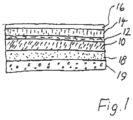
- the center of the inventive floor panel is a core 10 of a relatively highly filled, but still elastic plastic, especially PVC or polyurethane.
- a decor layer 12 such as a printed PVC film, which may be a decor of any type, for example a wood decor or also a stone decor and also any decor imaginable.
- the decor layer 12 is covered by a use surface or a finishing layer 14, which has a high abrasion resistance.
- a UV curable layer 16 on the surface. Curing by UV light has the particular advantage that the manufacturing process is accelerated.
- On the back of the panel there is a counteracting layer, which prevents curvature of the panel during expansion and shrinkage.
- a damping layer 19 may be provided, which additionally contributes to damping the sound of steps and/or of room noise.
- the layer 18 of Figure 1 may, in addition, carry out the function of a back pull and, at the same time, be a damping layer. It is, however, possible to divide the functions of a back pull layer and of a damping layer and have them carried out by two separate layers.
- the damping layer may be a foam layer, for example, of polyurethane. Fillers, especially mineral fillers, such as sand, chalk or the like may be present in the damping layer. These fillers increase weight and, with that, contribute to the damping. There may also be suitable fillers in the core 10.
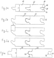
- Figure 2 shows different examples of the edge profile, which is to be used and enables adjacent panels to be locked.
- Figure 2a shows two adjacent tiles 20-22 with a lockable tongue and groove connection.
- the groove 24 has a straight flank 26, which extends parallel to the plane of the panel.
- the other flank 28 approaches the opposite flank 26 in the direction of the depth of the groove 24 and, at its open end, has a protrusion 30, which is directed inward in the direction of the opposite flank 26.
- this type of tongue and groove connection is partly undercut. However, it may be pressed together with a click effect, particularly since the material, as a whole, is relatively elastic and therefore deforms adequately, when two panels are to be connected with one another.
- the profile of Figure 2a is a typical locking profile.
- FIGS. 2b, 2c and 2d are similar to one another. Once again, they have a slightly undercut groove 32, which, on the whole, has a direction, rising into the interior of the material of the panels 20, 22, as well as an expanded head region at the base of the groove. Tongue and groove connections of this type can be caused to "interact” with one another, when two panels are to be connected with one another. In the case of profiles of this type, it is customary to speak of "angling profiles" or "only angling profiles”. To begin with, a new panel, which is to be added, is bent slightly and, after the tongue, which is not labeled, is pressed into the groove of the new panel, lowered into the flat position. In this way, adjacent panels, overcoming the undercuts of the tongue and groove connections, can be installed relatively easily and with little expenditure of force.
- Figure 2e shows a further locking profile, namely, an embodiment with a groove 34 and a tongue 36, which are close to one another in a tongue and groove connection, but have an expanded head region 38, 40.
- adjacent panels In view of the expansion of the head region, adjacent panels must be assembled with a certain pressure. The elastic material of the panels permits the tongues to be locked easily in the grooves.
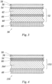
- Fig. 3 is a cross section through a floor panel 50 according to a second embodiment of the present invention.
- this floor panel 50 comprises a core 52 of elastic plastic which is deformable. This means that the core 52 can be deformed, for example, by bending but has the tendency to return to its original shape.
- An important difference between the core 10 shown in Fig. 1 and the core 52 of the floor panel 50 in Fig. 3 is that the core 52 has an inner laminate structure, which will be described in more detail in the following.
- a decor film 54 that is made of Polyvinylchloride (PVC) material which is printed with a decor of any type, for example a wood decor or a stone decor.
- the decor film 54 is covered by a finishing layer 56 which has a high abrasion resistance.
- the finishing layer 56 is also made of a thermoplastic plastic like Polyvinylchloride (PVC).
- the transparent finishing layer 56 has a haptic structure onto its upper surface that is imprinted by rolling or by any other mechanical embossing technique, such as with press plates.
- a UV curable transparent lacquer layer 58 applied on top of the finishing layer 56.
- This back-pull layer 60 which prevents a curvature of the panel during expansion or shrinkage.
- This back-pull layer 60 simultaneously acts as a sound damping layer. It is made of a recycled PVC material with fillers therein, especially mineral fillers, such a sand, chalk or the like. The fillers increase the weight and contribute to the sound damping properties.
- the core 52 comprises an upper core layer 62 and a lower core layer 64 disposed under the upper core layer 62.
- Both the upper core layer 62 and the lower core layer 64 are made of a soft Polyvinylchloride (PVC) material.
- PVC Polyvinylchloride
- This material can also comprise fillers, like the mineral fillers comprised within the back-pull layer 60. However, this may not necessarily be the case.
- a reinforcement layer 66 which is a glass fibre mat that is impregnated with a soft Polyvinylchloride (PVC) material.
- This reinforcement layer has the function to provide a dimensional stability to the core, to prevent an excessive shrinkage or expansion of the floor panel 50 due to a change of temperature.
- the reinforcement layer 66 has a high thermal stability, i.e. it hardly changes its dimensions in case of a thermal variation, especially in the horizontal direction parallel to the core layers 62 and 64. That is, the overall dimensional stability of the floor panel 50 is high even when the core layers 62 and 64 or other layers of the floor panel 50 have the tendency to shrink or to expand due to a rise or fall of the ground temperature or room temperature.
- the present inventors have found that the provision of the reinforcement layer 66 can reduce a thermal shrinkage or expansion of the floor panel 50 by up to 50%.
- Another important advantage of providing a reinforcement layer 66 to the core 52 is to improve the stability of the floor panel 50 against local pressure by a sharp object, for example, a piece of furniture. This is due to the fact that the dense fabric of the glass fibre mat that forms the reinforcement layer 66 provides a strong resistance to a local pressure by a sharp or pointed heavy object resting on top of the floor panel 50. Even if the top layers resting on the reinforcement layer 66, especially at least one of the upper core layer 62 and the decor film 54, are compressed punctually to some extend, this local compression will not cause a deterioration or even a lasting damage of the overall structure of the floor panel 50 because of the resistance of the reinforcement layer 66. However, the glass fibre mat can still be bent so as to keep the elastic properties of the floor panel 50 in a larger scale.
- a non-woven glass fibre mat can be used with a surface weight of 65 g/m2, a thermal dimensional stability represented by a dimensional change of 0.05 % in the lateral direction according to German industry standard DIN EN 434, and a mechanical stability against local pressure represented by a residual indentation of 0.07 mm according to standard DIN EN 433.
- the glass fibre mat be impregnated with a PVC material containing plasticizer in an amount from 15 % to 35 % of the PVC amount. Fillers can also be contained in the PVC material for impregnating the glass fibre mat.
- the reinforcement layer 66 is formed by immersing the non-woven glass fibre mat into a plasticizer based dispersion of liquid PVC.
- the upper core layer 62 consists of virgin polyvinyl chloride (PVC), while the lower core layer 64 consists of recycled PVC material.
- the content of plasticizer in the upper core layer 62 and the lower core layer 64 may vary accordingly.
- the content of plasticizer in the upper core layer 62 is 3.2 %, which is comparatively low, while the plasticizer content in the lower core layer 64 is 13.5 %.
- the overall content of plasticizer in the floor panel 50 may be 13.5 %.
- the overall content of fillers in this example of the laminate structure of the floor panel 50 is 48.4 %, wherein CaC03 is used as a filler material.
- a floor panel 50 according to Fig. 3 has an overall thickness of 5 mm, with the following thicknesses of its single layers: Finishing layer 56 0.3 to 0.7 mm Decor film 54 0.2mm Upper core layer 62 1.5 mm Reinforcement layer 66 0.5mm Lower core layer 64 1.5 mm Back-pull layer 60 1.0mm
- the transparent lacquer layer 58 has a comparatively low thickness of 0.0001 mm, for example.
- the laminate structure of the floor panel 50 in Fig. 3 comprises different layers of plastic materials but no wooden materials at all. It has excellent sound dampening properties, not only because of the structure of the back-pull layer 60. The remaining layers, especially the structure of the core 52, contribute to the sound dampening function, so that the floor panel 50 has such has an excellent quality under this aspect. Moreover, the whole floor panel 50 is elastic so that it can be bent and deformed but returns to its original flat shape when it is laid down on the floor in the installation process. No adhesive is necessary to install it.
- Another important advantage of the present floor panel 50 is that it can be cut with a sharp strong knife. No saw is necessary to cut the floor panel 50 into pieces, because it only comprises layers of plastic materials. This makes the installation process very easy even for inexperienced persons. In most cases even cutting at the surface of the floor panel 50 is sufficient to create a weakening line at the upper surface of the floor panel 50 so that it can be broken afterwards.
- the PVC material portion of the back-pull layer 60 can be a recycling material
- the upper layers of the floor panel 50 may consist of non recycling materials to avoid harmful gaseous emissions from the floor.
- the floor panel 50 of Fig. 3 is manufactured in a process as followed.
- the layers 54,56,62,64 and 60 are extruded.
- the upper core layer 62 and the lower core layer 64 are extruded from a soft Polyvinylchloride (PVC) material
- the decor film 54 is extruded of a Polyvinylchloride (PVC) material as well as. the transparent finishing layer 56.
- the back-pull layer 60 is extruded from a PVC material including sound dampening fillers like mineral fillers including chalk, sand or the like.
- the reinforcement layer 66 is created by providing a glass fibre mat and impregnating the glass fibre mat with a soft Polyvinylchloride (PVC) material. This can be performed by immersing the glass fibre mat into liquid PVC.
- PVC Polyvinylchloride
- the glass fibre mat can be non-woven glass fibre mat material that is immersed into a plasticizer based dispersion of PVC.
- the decor film 54 is printed with a decor after the extrusion process.
- the lamination structure of the floor panel 50 in Fig. 3 is created by applying the layers 54,56,60,62,64,66 onto each other, including the application of the reinforcement layer 66 between the upper core layer 62 and the lower core layer 64 so that the reinforcement layer 66 is sandwiched between these two layers 62,64 to form the core 52.
- the core 52, the decor film 54, the transparent finishing layer 56 and the back-pull layer 60 are bonded together by a calendaring process under an elevated temperature, including the application of pressure and heat to the laminate structure. This leads to a compact laminate structure with a relatively high weight but with a high elasticity and excellent sound dampening properties.
- the reinforcement layer 66 in the center of the core 52 improves the dimensional stability of the resulting floor panel 50 and makes it highly resistant against local pressure.
- a haptic structure can be imprinted onto the surface of the transparent finishing layer to imitate a wood structure.
- This imprinting process can be performed by rolling under heat and pressure to deform the surface of the transparent finishing layer 56. Structures resulting from this imprinting process are relatively deep, compared to the overall thickness of the floor panel 50.
- a transparent lacquer layer 58 is applied onto the transparent finishing layer 56, which is an UV curable lacquer layer.
- the individual extrusion processes for forming the core layers 62,64, the decor film 54, the transparent finishing layer 56 and the back-pull Iayer60 can be performed at the same time, as well as the process step of forming the reinforcement layer 66. Moreover, it is possible to apply all layers including the core 52, the decor film 54, the transparent finishing layer 56 and the back-pull layer 60 at the same time and to perform the calendaring process afterwards, or to apply one layer after the other and to perform the calendaring process afterwards.
- Fig. 4 shows a different embodiment of a floor panel 150, shown in a cross section.
- Some of the layers of the floor panel 150 are the same as those of the floor panel 50 in Fig. 3 , and so they are denoted with identical reference numbers.
- the floor panel 150 is also provided with a core 152 that has a structure different than the core 52 in Fig. 3 .
- the core 152 comprises only one core layer 164 of soft Polyvinylchloride (PVC) material.
- PVC Polyvinylchloride
- the reinforcement layer 66 is provided on this core layer 164.
- the structure of the reinforcement layer 66 as such is the same as described in connection with the floor panel 50, i.e.
- the reinforcement layer 66 comprises a glass fibre mat that is impregnated with a soft Polyvinylchloride (PVC) material.
- PVC Polyvinylchloride
- the decor film 54 is provided on top of the core 152 formed by the single core layer 164 and the reinforcement layer 66. That is, an upper core layer between the reinforcement layer 66 and the decor film 54 is omitted in the floor panel 150 in Fig. 4 .
- the manufacturing process of the floor panel 150 is mainly the same as with the floor panel 50, including the extrusion of the different layers 54,56,60,164 of plastic material, providing the reinforcement layer 66, applying all layers 54,56,60,164,66 together and bonding them together in a calendaring process. Afterwards the lacquer layer 58 can be applied.
- a floor panel 250 including a core 252 that also comprises one single core layer 262 of soft Polyvinylchloride (PVC) material and a reinforcement layer 66.
- PVC Polyvinylchloride
- the difference to the floor panel 150 described before in connection with Fig. 4 lies in the arrangement of the reinforcement layer 66, that is disposed beneath the single core layer 262 on top of the back-pull layer 60.
- Fig. 6 is plan view on a floor panel 50 according to the second embodiment of the present invention. It can be taken from Fig. 6 that the floor panel 50 has a rectangular shape. At its edges, floor panel 50 is provided with tongues and grooves for connected adjacent floor panels 50 with each other. In the following the longer edges of the floor panel 50 will be denoted as longitudinal edges, while the shorter edges will be referred to as traverse edges. At a first longitudinal edge 300 of the floor panel 50 (left longitudinal edge 300), there is provided a first groove 302 for receiving a first tongue with a complementary cross section. Such a first tongue 304 is provided at the opposite (second) longitudinal edge 306. This means that the floor panel 50 can be connected with another identical floor panel 50 on the left side in Fig.
- a protrusion 308 with a hook-like cross section is provided at the lower portion of the first longitudinal edge 300 of the panel 50.
- This protrusion 308 comprises a flat intermediate section 310 and a head 312 that forms the end of the protrusion 308.
- the head 312 has a thicker cross section in the vertical direction, compared to the intermediate section 310, so that the upper surface of the head 312 is slightly elevated over the top surface of the intermediate section 310. In this way the upper portion of the head 312 delimits a through-shaped groove 302 on top of the protrusion 308.
- the groove 302 is delimited by a wall 314 with a concave arc-shaped cross section.
- a second protrusion 316 protruding from the upper portion of the first longitudinal edge 300 of the panel 50, extending slightly over the groove 302 and closing it partially on its top side.
- This second protrusion 316 at the upper portion of the edge 300 of the panel 50 has the function to prevent a tongue 304 lying within the through-shaped groove 302 from being lifted out of the groove 302 in the vertical direction.
- the tongue 304 at the opposite longitudinal edge 306 is shown in Fig. 8 . It is formed at the bottom of a protrusion 318 protruding from the upper portion of the second longitudinal edge 306 of the panel 50.
- the tongue 304 itself extends slightly further than the protrusion 318 so that there is a step 320 on the top side of the longitudinal edge 306.
- the tongue 304 has an inclined arc-shaped wall 322 to be fitted onto the inner wall 314 of the groove 302 in Fig. 7 .
- the tongue 304 has a flat bottom 324 and an arc-shaped wall 326 at its bottom side facing the body of the floor panel 50.
- the tongue 304 of Fig. 8 is inserted into the groove 302 in Fig. 7 by inclining the floor panel 50 carrying the tongue 304 upwards so that the tongue 304 can be placed on top of the protrusion 308 of the other floor panel 50.
- the floor panel 50 carrying the tongue 304 can be laid down on the floor so that both floor panels 50 to be connected lie in the same plane.
- the bottom 324 of the tongue 304 rests on the ground of the groove 302, i.e. on top of the intermediate section 310 of the protrusion 308.
- both floor panels 50 can only be separated in a combined turning and lifting movement, turning the tongue 304 out of the groove 302 and taking it out.
- a second groove 334 is provided on top of a protrusion 336 with a hook-like cross section that extends from the lower portion of the first traverse edge 332 in a horizontal direction.
- the protrusion 336 extends along the whole length of the traverse edge 332 and comprises an intermediate portion 338 with a cross section of uniform height.
- the end of the protrusion 336 is formed by an extended head portion 340 with a thickness greater than that of the intermediate portion 338, so that the upper surface of the protrusion 336 has a step-like configuration, with a through-shaped groove 334 formed therein.
- the bottom of this groove 334 is formed by the upper surface of the intermediate portion 338, and the groove 334 is laterally delimited by the head portion 340 and an inclined wall 342 disposed at the body 344 of the floor panel 50.
- the groove 334 has a cross section of a trapezoidal shape.
- the panel body 344 is delimited by a vertical wall portion 346.
- the inclined wall portion 342 and the vertical wall portion 346 are separated by a horizontal ridge 348 extending towards the protrusion 336.
- the second traverse edge 330 is provided with a protrusion 350 extending from the upper portion of this traverse edge 330 in a horizontal direction.
- a second tongue 352 is provided that has a generally trapezoidal cross section that corresponds to that of the second groove 334 of Fig. 9 .
- the bottom surface of the protrusion 350 has a step-like configuration formed by the bottom 354 of the tongue 352 and an elevated bottom portion 356 that is located nearer to the body 358 of the floor panel 50 than the tongue 352.
- the tongue 352 is limited by an inclined wall 360 that forms a ridge 362 at its upper end. Above the ridge the protrusion 350 is delimited by a vertical wall portion 364.
- the tongue 352 and the groove 334 have a shape that allows to position the tongue 352 directly above the groove 334 by overlapping the protrusions 336 and 350 and to press the tongue 352 into the groove 334, so that the tongue 352 engages with the groove 334.
- Both the tongue 352 and the groove 334 are elastically deformable to be deformed during pressing the tongue 352 into the groove 334.
- the ridge 362 at the protrusion 350 can slide over the ridge 348 at the panel body 344 so that a tight connection between the two panel bodies 344 and 358 is formed.
- the strength of this connection is also provided by the elasticity of the tongue 352 and the groove 334 so that the tongue 352 can not simply be lifted out of the groove 334.
- connection between the traverse edges 330 and 332 does not require any tilting of the two floor panels 50 to be connected during insertion of the second tongue 352 into the second groove 334. It is rather sufficient to place the second tongue 352 at the traverse edge 330 above the second groove 334 of the other traverse edge 332 and to push it down, as described above.
- Laying a number of identical floor panels 50 can be performed as follows.
- a second row is already started by connecting a first panel 50 of this second row with its longitudinal edge 306 to a free longitudinal edge 300 of the first row
- each further panel 50 of the second row is laid down by positioning the first tongue 304 of its longitudinal edge 306 in the first groove 302 of the longitudinal edge 300 and laying it down, so that its traverse edge 330 carrying the second tongue 352 is pushed into the free second groove 334 of the traverse edge 332 of the floor panel 50 that has been laid down before.
Landscapes
- Engineering & Computer Science (AREA)
- Architecture (AREA)
- Civil Engineering (AREA)
- Structural Engineering (AREA)
- Floor Finish (AREA)
- Laminated Bodies (AREA)
Applications Claiming Priority (4)
| Application Number | Priority Date | Filing Date | Title |
|---|---|---|---|
| US13/214,175 US8728603B2 (en) | 2006-12-11 | 2011-08-20 | Floor panel |
| EP12761890.8A EP2744657B2 (fr) | 2011-08-20 | 2012-08-20 | Panneau de plancher multi-couche et elastique ayant un noyau de pvc renforcé |
| PCT/EP2012/003528 WO2013026559A2 (fr) | 2011-08-20 | 2012-08-20 | Panneau de plancher |
| EP17194029.9A EP3312362B1 (fr) | 2011-08-20 | 2012-08-20 | Panneau de plancher multi-couche et elastique ayant un noyau de pvc renforcé |
Related Parent Applications (2)
| Application Number | Title | Priority Date | Filing Date |
|---|---|---|---|
| EP17194029.9A Division EP3312362B1 (fr) | 2011-08-20 | 2012-08-20 | Panneau de plancher multi-couche et elastique ayant un noyau de pvc renforcé |
| EP12761890.8A Division EP2744657B2 (fr) | 2011-08-20 | 2012-08-20 | Panneau de plancher multi-couche et elastique ayant un noyau de pvc renforcé |
Publications (2)
| Publication Number | Publication Date |
|---|---|
| EP4151403A1 true EP4151403A1 (fr) | 2023-03-22 |
| EP4151403B1 EP4151403B1 (fr) | 2024-05-22 |
Family
ID=46888359
Family Applications (3)
| Application Number | Title | Priority Date | Filing Date |
|---|---|---|---|
| EP17194029.9A Active EP3312362B1 (fr) | 2011-08-20 | 2012-08-20 | Panneau de plancher multi-couche et elastique ayant un noyau de pvc renforcé |
| EP22199550.9A Active EP4151403B1 (fr) | 2011-08-20 | 2012-08-20 | Panneau de plancher multicouche avec noyau élastique |
| EP12761890.8A Active EP2744657B2 (fr) | 2011-08-20 | 2012-08-20 | Panneau de plancher multi-couche et elastique ayant un noyau de pvc renforcé |
Family Applications Before (1)
| Application Number | Title | Priority Date | Filing Date |
|---|---|---|---|
| EP17194029.9A Active EP3312362B1 (fr) | 2011-08-20 | 2012-08-20 | Panneau de plancher multi-couche et elastique ayant un noyau de pvc renforcé |
Family Applications After (1)
| Application Number | Title | Priority Date | Filing Date |
|---|---|---|---|
| EP12761890.8A Active EP2744657B2 (fr) | 2011-08-20 | 2012-08-20 | Panneau de plancher multi-couche et elastique ayant un noyau de pvc renforcé |
Country Status (8)
| Country | Link |
|---|---|
| US (1) | US8728603B2 (fr) |
| EP (3) | EP3312362B1 (fr) |
| DK (1) | DK2744657T3 (fr) |
| ES (2) | ES2931399T3 (fr) |
| HU (1) | HUE060520T2 (fr) |
| PL (2) | PL2744657T3 (fr) |
| PT (1) | PT3312362T (fr) |
| WO (1) | WO2013026559A2 (fr) |
Families Citing this family (63)
| Publication number | Priority date | Publication date | Assignee | Title |
|---|---|---|---|---|
| US8728603B2 (en) | 2006-12-11 | 2014-05-20 | Ulrich Windmöller Consulting GmbH | Floor panel |
| CN101910528B (zh) | 2007-11-07 | 2012-07-25 | 瓦林格创新股份有限公司 | 通过竖直卡合折叠实现的地板镶板的机械锁定和连接这种镶板的安装方法 |
| US8353140B2 (en) | 2007-11-07 | 2013-01-15 | Valinge Innovation Ab | Mechanical locking of floor panels with vertical snap folding |
| US11725395B2 (en) | 2009-09-04 | 2023-08-15 | Välinge Innovation AB | Resilient floor |
| US8365499B2 (en) | 2009-09-04 | 2013-02-05 | Valinge Innovation Ab | Resilient floor |
| CA3118821C (fr) | 2010-01-11 | 2023-09-26 | Valinge Innovation Ab | Revetement de sol a conception verrouillee |
| CN102155083B (zh) * | 2011-01-29 | 2014-07-23 | 刘谦益 | 一种地板连接结构 |
| RS54448B1 (en) * | 2011-02-01 | 2016-06-30 | Ivc Nv | PROCEDURE FOR THE PRODUCTION OF THE PLATE PRODUCT AND THE PLATE PRODUCED THEREOF |
| JP6105587B2 (ja) | 2011-08-29 | 2017-04-05 | セラロック、イノベーション、アクチボラグ | フロアパネル用機械式係止システム |
| CN102352684A (zh) * | 2011-09-05 | 2012-02-15 | 张家港市易华塑料有限公司 | 地板 |
| BE1022209B1 (nl) * | 2012-01-12 | 2016-03-01 | I.V.C. N.V. | Vloerpaneel |
| DE202012000284U1 (de) * | 2012-01-13 | 2012-05-23 | Floover World, S.L. | Vorgefertigtes laminiertes modulares Element für Böden |
| EP2812510B1 (fr) | 2012-02-07 | 2018-03-07 | Flooring Industries Limited, SARL | Panneau de sol destiné à former un revêtement de sol, revêtement de sol formé à partir de tels panneaux de sol et procédé permettant de fabriquer de tels panneaux de sol |
| BE1020722A3 (nl) * | 2012-06-01 | 2014-04-01 | Unilin Bvba | Paneel voor het vormen van een vloerbekleding en werkwijze voor het vervaardigen van dergelijke panelen. |
| UA111803C2 (uk) * | 2012-10-05 | 2016-06-10 | Кроноплюс Текнікал Аг | Підлогова панель для зовнішнього застосування |
| EP2978909B1 (fr) | 2013-03-25 | 2018-03-21 | Välinge Innovation AB | Plaques de plancher comprenant un système de verrouillage mécanique et procédé pour produire un tel système de verrouillage |
| US9133626B2 (en) | 2013-05-02 | 2015-09-15 | Tower Ipco Company Limited | Multi-purpose tile |
| US9643377B2 (en) | 2013-05-02 | 2017-05-09 | Tower Ipco Company Limited | Floor plank with foam core |
| CA2923429C (fr) * | 2013-09-16 | 2018-07-31 | Best Woods Inc. | Joints de raccordement de revetement de surface |
| US9121182B2 (en) * | 2013-09-25 | 2015-09-01 | George Atkinson | Weight room flooring system |
| US9765531B2 (en) | 2014-01-08 | 2017-09-19 | George Atkinson | Weight room floor covering |
| NL2013046B1 (en) | 2014-06-20 | 2016-07-06 | Champion Link Int Corp | Panel suitable for assembling a waterproof floor or wall covering, method of producing a panel. |
| JP6685273B2 (ja) | 2014-07-16 | 2020-04-22 | ベーリンゲ、イノベイション、アクチボラグVaelinge Innovation Ab | 熱可塑性の耐摩耗性箔を製造する方法 |
| WO2016029255A1 (fr) | 2014-08-29 | 2016-03-03 | Kell Richard William | Système de joint vertical pour un panneau de recouvrement de surface |
| NL2013486B1 (en) * | 2014-09-18 | 2016-09-28 | Champion Link Int Corp | Panel suitable for assembling a waterproof floor or wall covering, method of producing a panel. |
| US20160288447A1 (en) * | 2015-01-05 | 2016-10-06 | Eurico Januario Cordeiro | Waterproof composite core |
| EP3245352B1 (fr) * | 2015-01-15 | 2020-08-19 | Flooring Industries Limited, SARL | Panneau de plancher pour la formation d'un revêtement de plancher |
| WO2017121499A1 (fr) * | 2016-01-15 | 2017-07-20 | Beaulieu International Group Nv | Panneau de couverture et procédé de production de panneaux de couverture |
| LT3591000T (lt) | 2015-01-16 | 2023-07-25 | Beaulieu International Group Nv | Dengianti plokštė |
| DE102015106241A1 (de) | 2015-04-23 | 2016-10-27 | Döllken-Kunststoffverarbeitung Gmbh | Verfahren zum Herstellen eines dekorativen Profilkörpers, insbesondere einer Kantenleiste |
| BE1023446B1 (nl) | 2015-09-14 | 2017-03-22 | Ivc N.V. | Werkwijze voor het vervaardigen van vloerpanelen en vloerpaneel voor het vormen van een vloerbekleding |
| WO2017105335A1 (fr) | 2015-12-17 | 2017-06-22 | Välinge Innovation AB | Procédé de production d'un système de verrouillage mécanique destiné à des panneaux |
| CN105500867B (zh) * | 2016-01-20 | 2017-12-08 | 南京工业大学 | 一种新型的无金属连接件的复合材料夹层板连接结构及其设计方法 |
| US10094124B2 (en) | 2016-05-04 | 2018-10-09 | Wellmade Floor Covering Int'l Inc. | Engineered plank material having waterproofed veneer and its manufacturing method |
| US10544595B2 (en) | 2016-08-26 | 2020-01-28 | Quickstyle Industries Inc. | Tile with protected imitation grout line |
| US9938726B2 (en) | 2016-08-26 | 2018-04-10 | Quickstyle Industries Inc. | Densified foam core (DFC) tile with imitation grout line |
| AU2017335148B2 (en) | 2016-09-30 | 2023-04-20 | Välinge Innovation AB | Set of panels assembled by vertical displacement and locked together in the vertical and horizontal direction |
| BE1024617B1 (nl) | 2016-10-03 | 2018-05-02 | Ivc Bvba | Vloerpaneel en werkwijze voor het vervaardigen van een vloerpaneel. |
| BE1024723B1 (nl) * | 2016-11-10 | 2018-06-11 | Ivc Bvba | Vloerpaneel en werkwijze voor het vervaardigen van een vloerpaneel. |
| HUE059522T2 (hu) * | 2017-02-03 | 2022-11-28 | Xylo Tech Ag | PVC mûanyag panel |
| WO2018228654A1 (fr) | 2017-06-12 | 2018-12-20 | Knauf Gips Kg | Panneau de construction, destiné de préférence à un revêtement à l'intérieur d'un bâtiment |
| US11091918B2 (en) | 2017-07-13 | 2021-08-17 | Beaulieu International Group Nv | Covering panel and process of producing covering panels |
| PT3737802T (pt) | 2018-01-09 | 2023-07-19 | Vaelinge Innovation Ab | Conjunto de painéis |
| EP3737803A4 (fr) | 2018-01-10 | 2021-10-20 | Välinge Innovation AB | Joint de sous-plancher |
| BE1026356B1 (nl) | 2018-06-06 | 2020-01-17 | Ivc Bvba | Vloerpanelen |
| BE1026355B1 (nl) | 2018-06-06 | 2020-01-17 | Ivc Bvba | Vloerpanelen |
| CN113396263B (zh) | 2018-12-05 | 2023-02-21 | 瓦林格创新股份有限公司 | 底层地板接头 |
| EA202191590A1 (ru) * | 2018-12-05 | 2021-10-18 | И4Ф Лайсенсинг Нв | Декоративная панель и декоративное напольное покрытие, состоящее из указанных панелей |
| FR3091831B1 (fr) * | 2019-01-22 | 2020-12-25 | Gerflor | Structure multicouche pour la réalisation d’un revêtement de sol, et procédé de fabrication d’une telle structure multicouche |
| WO2020159353A1 (fr) * | 2019-01-30 | 2020-08-06 | Floor Locking Technology B.V. | Panneau et revêtement de plancher le comprenant |
| DE202019101580U1 (de) * | 2019-03-20 | 2020-06-30 | Otto Fuchs - Kommanditgesellschaft - | Profilverbund |
| EP3946940A1 (fr) | 2019-03-25 | 2022-02-09 | Flooring Industries Limited, SARL | Panneau et procédé de fabrication d'un panneau |
| US11260619B2 (en) * | 2019-04-25 | 2022-03-01 | The Boeing Company | Composite panel systems and methods |
| NL2024630B1 (en) * | 2020-01-09 | 2021-09-07 | I4F Licensing Nv | Glue-down decorative floor covering system |
| CA3163661A1 (fr) * | 2020-01-09 | 2021-07-15 | Eddy Alberic Boucke | Systeme de revetement de sol decoratif adhesif |
| EP4161989A1 (fr) * | 2020-06-08 | 2023-04-12 | Eastman Chemical Company | Compositions à base d'ester de cellulose et articles formés à partir de celles-ci |
| US11788302B2 (en) * | 2020-06-12 | 2023-10-17 | Välinge Innovation AB | Building panel comprising mineral-based layer |
| DE102020007039A1 (de) * | 2020-10-16 | 2022-04-21 | Parador Gmbh | Verfahren zur Herstellung einer Polyvinylchlorid-freien Deckschicht, Polyvinylchlorid-freie Deckschicht sowie Belagselement |
| US20220136236A1 (en) * | 2020-11-04 | 2022-05-05 | ROM Development Corp. | Fire-resistant composite structural building panels |
| BE1029240B1 (nl) | 2021-03-24 | 2022-10-24 | Flooring Ind Ltd Sarl | Panelen en methode om panelen te produceren |
| LU501429B1 (en) | 2022-02-09 | 2023-08-09 | Tarkett Gdl Sa | Hybrid acoustic floor panel |
| WO2024009238A1 (fr) | 2022-07-07 | 2024-01-11 | Flooring Industries Limited, Sarl | Panneau décoratif et procédé de fabrication d'un panneau décoratif |
| EP4364961A1 (fr) | 2022-11-03 | 2024-05-08 | Unilin, BV | Panneau décoratif et procédé de fabrication des panneaux décoratifs |
Citations (6)
| Publication number | Priority date | Publication date | Assignee | Title |
|---|---|---|---|---|
| GB1430423A (en) | 1973-05-09 | 1976-03-31 | Gkn Sankey Ltd | Joint structure |
| EP0698126A1 (fr) | 1993-05-21 | 1996-02-28 | PRS PIPE & RECYCLING SUPPLY S.A. | Procede et installation pour la recuperation d'au moins un metal contenu dans des dechets et rebuts de produits industriels |
| EP0843763A1 (fr) | 1996-06-11 | 1998-05-27 | Unilin Beheer B.V. | Revetement de sol compose de panneaux de plancher durs et procede de fabrication de ces panneaux de plancher |
| WO2007052885A1 (fr) * | 2005-11-07 | 2007-05-10 | Lg Chem, Ltd. | Revetement de sol de type dalles a motifs d’impression et de coupe harmonieux, et son procede de pose |
| EP1938963A1 (fr) * | 2006-12-11 | 2008-07-02 | Ulrich Windmöller Consulting GmbH | Panneau de sol |
| EP2339092A1 (fr) * | 2009-12-22 | 2011-06-29 | Flooring Industries Limited, SARL | Panneau de revêtement et procédé de mise en place de tels panneaux |
Family Cites Families (26)
| Publication number | Priority date | Publication date | Assignee | Title |
|---|---|---|---|---|
| GB1206584A (en) | 1966-08-12 | 1970-09-23 | Marley Tile Co Ltd | Improvements in or relating to flooring materials and methods for the manufacture thereof |
| US6345481B1 (en) * | 1997-11-25 | 2002-02-12 | Premark Rwp Holdings, Inc. | Article with interlocking edges and covering product prepared therefrom |
| WO1999028767A1 (fr) | 1997-12-01 | 1999-06-10 | Schlumberger Limited | Procede et appareil permettant de creer, tester et modifier des modeles de subsurfaces geologiques |
| DE19944399A1 (de) | 1999-09-16 | 2001-04-12 | Wpt Gmbh Polymertechnik | Fussbodenelement mit klangarmer Trägerschicht |
| SE516696C2 (sv) | 1999-12-23 | 2002-02-12 | Perstorp Flooring Ab | Förfarande för framställning av ytelement vilka innefattar ett övre dekorativt skikt samt ytelement framställda enlit förfarandet |
| FR2805549B1 (fr) * | 2000-02-29 | 2003-09-26 | Taraflex | Revetement de sol en matiere plastique et procede pour son obtention |
| US20040003888A1 (en) * | 2000-07-11 | 2004-01-08 | Laurence Mott | Process for the manufacture of an improved floor element |
| US6803110B2 (en) | 2001-01-22 | 2004-10-12 | Formica Corporation | Decorative laminate assembly and method for producing same |
| EP1262607B1 (fr) | 2001-05-25 | 2004-09-22 | Windmöller Consulting GmbH Ulrich | Procédé de fabrication d'un panneau pour revêtement de sol |
| DE10151614C1 (de) * | 2001-10-23 | 2003-04-24 | Kaindl Wals M | Paneel mit schallverbessernder Schicht nebst Herstellungsverfahren |
| US8850769B2 (en) | 2002-04-15 | 2014-10-07 | Valinge Innovation Ab | Floorboards for floating floors |
| US6869985B2 (en) * | 2002-05-10 | 2005-03-22 | Awi Licensing Company | Environmentally friendly polylactide-based composite formulations |
| DE20214532U1 (de) | 2002-09-20 | 2004-02-19 | Hw-Industries Gmbh & Co. Kg | Verkleidungsplatte |
| DE10316886B4 (de) | 2003-04-12 | 2010-04-15 | Volker Kettler | Elastischer Bodenbelag und Verfahren zu dessen Herstellung |
| DE102004011531C5 (de) | 2004-03-08 | 2014-03-06 | Kronotec Ag | Holzwerkstoffplatte, insbesondere Fußbodenpaneel |
| KR200370449Y1 (ko) | 2004-06-22 | 2004-12-17 | 주식회사 엘지화학 | 합성수지를 이용한 표면층 및 목질계 보드를 포함하는마루바닥재 |
| DE202004014160U1 (de) | 2004-09-09 | 2004-11-18 | Mohr, Wolfgang | Bodenbelagelement |
| DE102005023661B4 (de) | 2005-05-23 | 2024-05-23 | Pergo (Europe) Ab | Fußbodenbpaneel |
| US7155871B1 (en) | 2005-12-29 | 2007-01-02 | Tru Woods Limited | Floor plank |
| US7458191B2 (en) | 2005-12-29 | 2008-12-02 | Tru Woods Limited | Floor tile |
| DE102006001972A1 (de) | 2006-01-13 | 2007-08-09 | WKP Württembergische Kunststoffplatten-Werke GmbH & Co. KG | Flexibler Bodenbelag |
| US8728603B2 (en) | 2006-12-11 | 2014-05-20 | Ulrich Windmöller Consulting GmbH | Floor panel |
| CN101881076B (zh) | 2010-06-09 | 2014-07-09 | 黄焕文 | 一种方便铺的组合式地板 |
| BE1019331A5 (nl) | 2010-05-10 | 2012-06-05 | Flooring Ind Ltd Sarl | Vloerpaneel en werkwijzen voor het vervaardigen van vloerpanelen. |
| KR101304604B1 (ko) | 2010-05-27 | 2013-09-05 | (주)엘지하우시스 | 미끄러짐 방지용 비닐 바닥재 및 그 제조방법 |
| EP2586929B1 (fr) * | 2011-10-28 | 2019-06-19 | U. Windmöller Consulting GmbH & Co. KG | Revêtement de sol |
-
2011
- 2011-08-20 US US13/214,175 patent/US8728603B2/en active Active
-
2012
- 2012-08-20 WO PCT/EP2012/003528 patent/WO2013026559A2/fr active Application Filing
- 2012-08-20 ES ES17194029T patent/ES2931399T3/es active Active
- 2012-08-20 EP EP17194029.9A patent/EP3312362B1/fr active Active
- 2012-08-20 PT PT171940299T patent/PT3312362T/pt unknown
- 2012-08-20 DK DK12761890.8T patent/DK2744657T3/en active
- 2012-08-20 ES ES12761890.8T patent/ES2652033T3/es active Active
- 2012-08-20 HU HUE17194029A patent/HUE060520T2/hu unknown
- 2012-08-20 EP EP22199550.9A patent/EP4151403B1/fr active Active
- 2012-08-20 PL PL12761890T patent/PL2744657T3/pl unknown
- 2012-08-20 EP EP12761890.8A patent/EP2744657B2/fr active Active
- 2012-08-20 PL PL17194029.9T patent/PL3312362T3/pl unknown
Patent Citations (8)
| Publication number | Priority date | Publication date | Assignee | Title |
|---|---|---|---|---|
| GB1430423A (en) | 1973-05-09 | 1976-03-31 | Gkn Sankey Ltd | Joint structure |
| EP0698126A1 (fr) | 1993-05-21 | 1996-02-28 | PRS PIPE & RECYCLING SUPPLY S.A. | Procede et installation pour la recuperation d'au moins un metal contenu dans des dechets et rebuts de produits industriels |
| EP0843763A1 (fr) | 1996-06-11 | 1998-05-27 | Unilin Beheer B.V. | Revetement de sol compose de panneaux de plancher durs et procede de fabrication de ces panneaux de plancher |
| EP1024234A2 (fr) | 1996-06-11 | 2000-08-02 | Unilin Beheer B.V. | Revêtement de sol composé de panneaux de planchers durs et procédé de fabrication de ces panneaux de plancher |
| EP1026341A2 (fr) | 1996-06-11 | 2000-08-09 | Unilin Beheer B.V. | Revêtement de sol composé de panneaux de plancher durs et procédé de fabrication de ces panneaux de plancher |
| WO2007052885A1 (fr) * | 2005-11-07 | 2007-05-10 | Lg Chem, Ltd. | Revetement de sol de type dalles a motifs d’impression et de coupe harmonieux, et son procede de pose |
| EP1938963A1 (fr) * | 2006-12-11 | 2008-07-02 | Ulrich Windmöller Consulting GmbH | Panneau de sol |
| EP2339092A1 (fr) * | 2009-12-22 | 2011-06-29 | Flooring Industries Limited, SARL | Panneau de revêtement et procédé de mise en place de tels panneaux |
Also Published As
| Publication number | Publication date |
|---|---|
| EP2744657B1 (fr) | 2017-10-04 |
| PL2744657T3 (pl) | 2018-02-28 |
| DK2744657T3 (en) | 2017-12-04 |
| EP3312362B1 (fr) | 2022-10-05 |
| PL3312362T3 (pl) | 2023-01-30 |
| EP2744657A2 (fr) | 2014-06-25 |
| EP2744657B2 (fr) | 2020-09-23 |
| ES2931399T3 (es) | 2022-12-28 |
| PT3312362T (pt) | 2022-11-25 |
| WO2013026559A2 (fr) | 2013-02-28 |
| ES2652033T3 (es) | 2018-01-31 |
| US8728603B2 (en) | 2014-05-20 |
| EP3312362A1 (fr) | 2018-04-25 |
| WO2013026559A3 (fr) | 2013-10-24 |
| EP4151403B1 (fr) | 2024-05-22 |
| US20110296780A1 (en) | 2011-12-08 |
| HUE060520T2 (hu) | 2023-03-28 |
Similar Documents
| Publication | Publication Date | Title |
|---|---|---|
| EP4151403B1 (fr) | Panneau de plancher multicouche avec noyau élastique | |
| US8071193B2 (en) | Floor panel | |
| EP2957691B1 (fr) | Panneau approprié pour l'assemblage d'un revêtement de plancher ou de paroi étanche à l'eau, procédé de production d'un panneau | |
| US11649642B2 (en) | Mechanical locking system for floor panels | |
| US9643377B2 (en) | Floor plank with foam core | |
| US9347469B2 (en) | Mechanical locking system for floor panels | |
| US8037656B2 (en) | Flooring boards with press down locking mechanism | |
| CN101581145B (zh) | 用于地板面板的机械锁定系统 | |
| EP3521529A1 (fr) | Panneau permettant de former un revêtement de sol et procédé de fabrication desdits panneaux | |
| KR20070003858A (ko) | 마루 커버링 및 잠금 시스템 및 예를 들어 마루판을제조하기 위한 장치 | |
| RU2618247C2 (ru) | Сердцевина, заготовка панели, половая панель и способы их изготовления | |
| EP3192939B1 (fr) | Plinthe, systeme de décoration et procede de fabrication de plinthe | |
| EP3141674A1 (fr) | Élément de plancher à noyau en mousse | |
| KR101166284B1 (ko) | 클릭 합판마루 | |
| US11794459B1 (en) | Composite panels and methods for making the same |
Legal Events
| Date | Code | Title | Description |
|---|---|---|---|
| PUAI | Public reference made under article 153(3) epc to a published international application that has entered the european phase |
Free format text: ORIGINAL CODE: 0009012 |
|
| STAA | Information on the status of an ep patent application or granted ep patent |
Free format text: STATUS: THE APPLICATION HAS BEEN PUBLISHED |
|
| AC | Divisional application: reference to earlier application |
Ref document number: 2744657 Country of ref document: EP Kind code of ref document: P Ref document number: 3312362 Country of ref document: EP Kind code of ref document: P |
|
| AK | Designated contracting states |
Kind code of ref document: A1 Designated state(s): AL AT BE BG CH CY CZ DE DK EE ES FI FR GB GR HR HU IE IS IT LI LT LU LV MC MK MT NL NO PL PT RO RS SE SI SK SM TR |
|
| P01 | Opt-out of the competence of the unified patent court (upc) registered |
Effective date: 20230523 |
|
| STAA | Information on the status of an ep patent application or granted ep patent |
Free format text: STATUS: REQUEST FOR EXAMINATION WAS MADE |
|
| RAP3 | Party data changed (applicant data changed or rights of an application transferred) |
Owner name: VAELINGE INNOVATION AB Owner name: FLOORING INDUSTRIES LIMITED, SARL Owner name: I4F LICENSING NV |
|
| 17P | Request for examination filed |
Effective date: 20230922 |
|
| RBV | Designated contracting states (corrected) |
Designated state(s): AL AT BE BG CH CY CZ DE DK EE ES FI FR GB GR HR HU IE IS IT LI LT LU LV MC MK MT NL NO PL PT RO RS SE SI SK SM TR |
|
| GRAP | Despatch of communication of intention to grant a patent |
Free format text: ORIGINAL CODE: EPIDOSNIGR1 |
|
| STAA | Information on the status of an ep patent application or granted ep patent |
Free format text: STATUS: GRANT OF PATENT IS INTENDED |
|
| RIC1 | Information provided on ipc code assigned before grant |
Ipc: F16B 5/00 20060101ALN20231114BHEP Ipc: B32B 3/06 20060101ALI20231114BHEP Ipc: B32B 38/00 20060101ALI20231114BHEP Ipc: B32B 38/08 20060101ALI20231114BHEP Ipc: B32B 37/15 20060101ALI20231114BHEP Ipc: B32B 27/30 20060101ALI20231114BHEP Ipc: E04F 15/10 20060101ALI20231114BHEP Ipc: B32B 27/20 20060101ALI20231114BHEP Ipc: B32B 27/12 20060101AFI20231114BHEP |
|
| INTG | Intention to grant announced |
Effective date: 20231211 |
|
| GRAS | Grant fee paid |
Free format text: ORIGINAL CODE: EPIDOSNIGR3 |
|
| RAP1 | Party data changed (applicant data changed or rights of an application transferred) |
Owner name: VAELINGE INNOVATION AB Owner name: UNILIN, BV Owner name: I4F LICENSING NV |
|
| GRAA | (expected) grant |
Free format text: ORIGINAL CODE: 0009210 |
|
| STAA | Information on the status of an ep patent application or granted ep patent |
Free format text: STATUS: THE PATENT HAS BEEN GRANTED |
|
| AC | Divisional application: reference to earlier application |
Ref document number: 2744657 Country of ref document: EP Kind code of ref document: P Ref document number: 3312362 Country of ref document: EP Kind code of ref document: P |
|
| AK | Designated contracting states |
Kind code of ref document: B1 Designated state(s): AL AT BE BG CH CY CZ DE DK EE ES FI FR GB GR HR HU IE IS IT LI LT LU LV MC MK MT NL NO PL PT RO RS SE SI SK SM TR |
|
| REG | Reference to a national code |
Ref country code: GB Ref legal event code: FG4D |