EP4148286B1 - Befestigung mit spanngurt - Google Patents
Befestigung mit spanngurt Download PDFInfo
- Publication number
- EP4148286B1 EP4148286B1 EP22193646.1A EP22193646A EP4148286B1 EP 4148286 B1 EP4148286 B1 EP 4148286B1 EP 22193646 A EP22193646 A EP 22193646A EP 4148286 B1 EP4148286 B1 EP 4148286B1
- Authority
- EP
- European Patent Office
- Prior art keywords
- support
- strap
- fastener system
- equipment
- fixing system
- Prior art date
- Legal status (The legal status is an assumption and is not a legal conclusion. Google has not performed a legal analysis and makes no representation as to the accuracy of the status listed.)
- Active
Links
Images



Classifications
-
- F—MECHANICAL ENGINEERING; LIGHTING; HEATING; WEAPONS; BLASTING
- F16—ENGINEERING ELEMENTS AND UNITS; GENERAL MEASURES FOR PRODUCING AND MAINTAINING EFFECTIVE FUNCTIONING OF MACHINES OR INSTALLATIONS; THERMAL INSULATION IN GENERAL
- F16B—DEVICES FOR FASTENING OR SECURING CONSTRUCTIONAL ELEMENTS OR MACHINE PARTS TOGETHER, e.g. NAILS, BOLTS, CIRCLIPS, CLAMPS, CLIPS OR WEDGES; JOINTS OR JOINTING
- F16B2/00—Friction-grip releasable fastenings
- F16B2/02—Clamps, i.e. with gripping action effected by positive means other than the inherent resistance to deformation of the material of the fastening
- F16B2/06—Clamps, i.e. with gripping action effected by positive means other than the inherent resistance to deformation of the material of the fastening external, i.e. with contracting action
- F16B2/08—Clamps, i.e. with gripping action effected by positive means other than the inherent resistance to deformation of the material of the fastening external, i.e. with contracting action using bands
Definitions
- Certain equipment, and in particular telecommunications modules making it possible to improve the power of signals, are intended to be fixed on a support by the user who has just acquired it.
- 5G amplifiers booster
- the user in possession of the equipment must fix the equipment themselves on any support outside their home, for example on a post, a mast, a gutter downspout, a guardrail bar 'a balcony, etc.
- the equipment must therefore be equipped with a simple-to-use fixing system, requiring no tools, and allowing anyone, particularly people with little DIY skills, to effectively fix the equipment on its support.
- such a fixing system conventionally comprises a strap which is adjusted and tightened by the user around the support.
- clamping clamps ensure locking when the balance point position (alignment of the articulation points) is exceeded.
- the clamps do not have significant adjustment latitude, and the user must therefore be able to assess whether the clamping force is sufficient.
- the quality of the fixing will therefore depend on the user's abilities in this area. This is very problematic, because the user is not a professional and their mechanical/DIY skills are often limited. It is therefore common for equipment to be poorly secured, or damaged by poorly controlled tightening.
- the document US 6,185,303 B1 discloses a bracket for mounting an enclosure to a support structure, and in particular a mounting bracket kit for removably mounting an enclosure to a pole.
- the subject of the invention is a fixing system making it possible to fix equipment on a support, which is simple to use, which does not require tools, and which makes it possible to obtain a suitable, sufficient and independent tightening force. 'user.
- the fixing system according to the invention does not require any tools and is very simple to use: simply position the fixing system on the support, surround the support with the strap, and pull on the first end of the strap.
- the elastic device whose elongation is limited by the stop, makes it possible to stress the clamping with a calibrated, repeatable tension, and independent of any perception of the user: the tightening force depends on the elongation of the elastic device and not of the action of the user. Tightening is controlled regardless of the position, orientation, dimensions and shape of the support.
- the invention offers great latitude for adjusting the length of the strap while ensuring an unambiguous guarantee of tensioning.
- a fixing system as previously described, further comprising an opening and locking device arranged to, in response to a manual opening action, open the fixing system and thus allow the strap to be positioned around of support, and to, in response to a manual locking action, close and lock the fixing system.
- a fixing system as previously described, comprising, for at least one of the support surfaces, a recess defining two distinct support portions of said support surface, the strap being able, depending on dimensions of the support, pass into the recess between said support portions.
- a fixing system as previously described, comprising two support surfaces, as well as a positioning plate comprising two plates on which the two support surfaces are formed, the positioning plate comprising two lateral surfaces to which and between which the plates are fixed.
- each support surface comprising an anti-slip pad.
- a fixing system as previously described, in which a second end of the strap is connected to a first anchor point, the first end of the elastic device is connected to the adjustment device and/or to the fixing device. opening and locking, a second end of the elastic device is connected to a second anchor point, the first anchor point and the second anchor point being fixed relative to the support surface(s).
- the elastic device comprises a spring.
- the elastic device comprises several elastic sub-elements.
- a fixing system as previously described, further comprising an orientation device arranged to allow the equipment to be oriented according to a predefined orientation whatever the orientation of the support.
- the orientation device being arranged to be positioned between the equipment and the positioning plate.
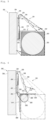
- the fixing support according to a first embodiment of the invention 1 is intended to fix equipment 2 to a support 3.
- Equipment 2 here is a telecommunications module, for example a 5G amplifier. Equipment 2 is here intended to be positioned outdoors.
- the support 3 is here a horizontal support, of tubular shape having a circular section.
- the support 3 is for example a bar of a balcony railing.
- the diameter of the section of support 3 is for example equal to 10cm.
- the support 3 is a vertical support, or the support 3 is a support oriented along any plane.
- the equipment 2 comprises a housing 4 having here a general parallelepiped shape with rounded edges.
- the invention can be implemented whatever the shape of the housing, which could therefore be different, for example frustoconical.
- the preferred operating position of equipment 2 corresponds to the vertical position and orientation visible on the figures 1 to 3 .
- the housing 4 of the equipment 2 comprises an upper face 5, a lower face 6, two side faces 7, a front face 8 and a rear face 9.
- the terms “upper”, “lower”, “front”, “rear » therefore correspond to an arrangement of the equipment 2 according to its preferred operating position.
- the fixing system 1 extends from the rear face 9 of the housing 4 of the equipment 2.
- the fixing system 1 firstly comprises a base 10 of cylindrical shape having an axis has an external face 11.
- the base 10 is polygonal in shape.
- the base 10 optionally integrates an orientation device 12 of the equipment 2, which makes it possible to manually orient the equipment 2 so that it can be oriented according to a predefined orientation whatever the orientation of the support 3.
- the predefined orientation here corresponds to the preferred operating position of the equipment 2.
- the orientation device 12 comprises a fixed portion relative to the rest of the fixing system 1, and a rotating portion, around the axis X, relative to the fixed portion, the rotating portion being fixed relative to the housing 4 of equipment 2.
- a manual action consisting of exerting pressure on the rotating portion and therefore on the equipment 2, makes it possible to unlock the orientation device 12 (the unlocking could alternatively be carried out by exerting pressure on the fixed portion and therefore on the fixing system).
- the rotating portion can then be manually rotated by the user to orient the equipment 2 relative to the fixing system 1, and give it the predefined orientation.
- the orientation device 12 locks and the rotating portion can no longer be rotated (except by pressing again on the rear of the fixing system 1).
- the orientation device 12 also includes markers 13 marked on the rear face 9 of the housing 4 of the equipment 2, which make it possible to designate the different possible orientations of the equipment 2.
- the orientation device 12 therefore makes it possible to follow the possible inclination of the support 3 so that the equipment 2 maintains a recommended orientation for proper operation.
- the orientation is preferably (but not necessarily) given to the equipment 2 prior to the installation of the fixing system 1 on the support 3.
- the fixing system 1 further comprises a positioning plate 14 which extends from the external face 11 of the base 10.
- the optional orientation device 12 is therefore positioned between the equipment 2 and the positioning plate 14.
- the positioning plate 14 is integral in rotation with the fixed portion of the orientation device 12.
- the positioning plate 14 comprises a fixing bracket 15 comprising two lateral surfaces 16 which extend from the external face 11 of the base 10, perpendicular thereto.
- Ribs 17 form lateral reinforcements for positioning the lateral surfaces 16.
- the positioning plate 14 comprises a first plate 18 extending in a first plane P1 perpendicular to the rear face 9 of the housing 4 of the equipment 2, and a second plate 19 extending in a second plane P2 perpendicular to the first plane P1 and therefore parallel to the rear face 9 of the housing 4.
- the first plate 18 and the second plate 19 extend between the side surfaces 16 of the fixing bracket 15, being fixed to said side surfaces 16.
- the first plate 18 comprises a lower face on which a first bearing surface 20 is formed.
- the second plate 19 comprises a rear face on which the second bearing surface 21 is formed.
- the positioning plate 14 also includes a foot 22.
- the foot 22 is formed by a plate which extends perpendicularly from a front face of the second plate 19 (opposite to the second support surface 21), and which makes it possible to fix the positioning plate 14 on the external face 11 of the base 10.
- a first recess 24, of rectangular shape, is formed in the first plate 18.
- the first recess 24 extends from a central portion of the edge of the first plate 18.
- the first recess 24 defines a first support portion 25 and a second support portion 26 of the first support surface 20, located on either side of the first recess 24.
- a second recess 27, of rectangular shape, is formed in the second plate 19.
- the second recess 27 delimits a longitudinal cavity in the plate 14.
- the second recess 27 extends into a central portion of the second plate 19, perpendicular to the foreground P1.
- the second recess 27 defines a first support portion 28 and a second support portion 29 of the second support surface 21, located on either side of the second recess 27.
- the first recess 24, respectively the second recess 27, allows the positioning plate 14 to be compatible with a wide dimensional range of support 3. This wide dimensional range is the cause of the movement of the two strands of the strap 35, justifying the presence of the first recess 24 and the second recess 27.
- Each support surface 20, 21 here comprises a pad which is fixed (by being for example glued, welded, etc.) on the corresponding plate.
- the pads prevent damage to the support 3 (by scratching it for example). Note that each skate and the associated plate (and even the entire plate) could form a unique piece.
- the fixing system 1 also comprises a first anchor point 30 and a second anchor point 31, which are fixed relative to the positioning plate 14, and therefore relative to the support surfaces 20, 21, and therefore relative to the housing 4 of the equipment 2 (at least when the orientation device 12 is locked).
- the first anchor point 30 and the second anchor point 31 are here both positioned between the second plate 19 and the external face 11 of the base 10.
- Each anchor point 30, 31 comprises an axis fixed on the fixing bracket 15, each end of said axis being fixed to a separate lateral surface 16.
- the fixing system 1 also includes a return roller 33, which is rotatably mounted around an axis parallel to the axes of the anchoring points, or which comprises a smooth material having little adhesion.
- the return roller 33 is positioned at the level of an upper portion of the external face 11 of the base 10. Each end of the return roller 33 is fixed to a distinct side surface 16.
- the fixing system 1 further comprises a main strap 35 which is intended to surround the support 3, and to hold the fixing system 1 and therefore the equipment 2 on the support 3.
- the main strap 35 has a first end 36 and a second end 37 which is here connected to the first anchor point 30. More precisely, the second end 37 of the strap 35 has been passed around the axis of the first anchor point. anchor 30 then folded and fixed to the rest of the strap 35 (by being for example glued, welded, sewn, etc.).
- the strap 35 when the strap 35 surrounds the support, it can pass, depending on the dimensions of said support 3, in the first recess 24 and/or in the second recess 27 (when they are respectively present).
- the fixing system 1 further comprises a device 38 for adjusting the length of the strap, and an opening and locking device 39.
- the adjustment device 38 makes it possible to manually adjust the length of the strap 35 around the support 3.
- the adjustment device 38 is anti-return. It can be released by a simple manual action of the user.
- the opening and locking device 39 allows, in response to a manual opening action, to open the fixing system 1 and thus to position the main strap 35 around the support 3.
- the opening and locking device 39 also allows, in response to a manual locking action, to close and lock the fixing system 1.
- the adjustment device 38 and the opening and locking device 39 are here integrated in the same module, in this case an adjustable clip buckle 40.
- the adjustable clip buckle 40 comprises a male part 41 and a female part 42.
- the male part 41 comprises a male elastic interlocking mechanism, comprising three teeth including two external teeth 43 each provided at its free end with a hook facing outwards, as well as two openings 44.
- the female part 42 comprises a female elastic nesting mechanism, complementary to the male elastic nesting mechanism, as well as an opening 45.
- the fixing system 1 also includes a secondary strap 46.
- the secondary strap 46 comprises a first end connected to the female part 42 of the adjustable clip buckle 40 (passing through the opening 45).
- the secondary strap 46 passes behind the return roller 33 and therefore comprises a first portion parallel to the rear face 9 of the housing 4 and a second portion which extends in the direction of the main strap 35.
- the first end 36 of the main strap 35 passes through one then the other of the openings 44 of the male part 41 of the adjustable clip buckle 40, which allows, by pulling on the first end 36 to the main strap 35, to adjust its length (or, more precisely, to adjust the length of the portion of the main strap 35 which tightens the support 3).
- the fixing system 1 further comprises an elastic device, which in this case is a metal tension spring 50.
- a first end of the spring 50 is connected to the adjustment device 38 and/or to the opening and locking device 39.
- the first end of the spring 50 is connected to the second end of the secondary strap 46 via a buckle 51 ( and therefore to the adjustable clip buckle 40 via the buckle 51 and the secondary strap 46).
- a second end of the spring 50 is connected to the second anchor point 31.
- the spring 50 is positioned between the second plate 19 of the positioning plate 14 and the orientation device 12.
- the spring 50 is located between the two lateral surfaces 16 of the fixing bracket 15 being very close to the external face 11 of the base 10. This position of the spring makes it possible to improve the compactness of the fixing system 1.
- the spring 50 extends and lengthens in a direction perpendicular to the first plane P1 and parallel to the second plane P2. This configuration is of course not obligatory.
- stiffness of the spring 50 is not too high in order to make the device fairly precise.
- K being the stiffness (in N/mm), F the force (in N) and A the elongation (in mm).
- the stiffness of the spring is between 1 and 2.5N/mm.
- K being the stiffness (in N.m/rad)
- C the torque (in N.m)
- ⁇ the angle (in rad) between the ends of the spring.
- spring 50 linear measures 30mm when not elongated, and extends by 30mm; its length when lying down is therefore 60mm. It produces a tension of 50N in the strap 35, which gives a stiffness of 1.66N/mm.
- the fixing system 1 further comprises a mechanical stop 52, which extends under the return roller 33 from an upper portion of the external face 11 of the base 10.
- the stop 52 is located opposite the first end of the spring 50.
- the user exerts a manual opening action on the opening and locking device 39 to open the fixing system 1.
- the manual opening action simply consists of pressing on the external teeth 43 of the male part 41 of the adjustable clip buckle 40, and to move said male part 41 away from the female part 42.
- the user then presents the positioning plate 14 against the support 3.
- the first support surface 20 and the second support surface 21 are applied against the support 3.
- the user wraps (circles) the main strap 35 around the support 3, then exerts a manual locking action on the opening and locking device 39 to close and lock the fixing system 1.
- the manual locking action consists simply fit the male part 41 of the adjustable clip buckle 40 into the female part 42.
- the adjustment device 38 thus adjusts the length of the strap 35 to the dimensions of the support 3, then the strap 35 acts on the first end of the spring 50 via the adjustable clip buckle 40, the secondary strap 46, the return roller 33 and the loop 51, so that the spring 50 undergoes an elongation which generates a tension force of the strap 35 allowing to tighten it around the support 3.
- the mechanical stop 52 limits the extension of the spring 50 to give the tension force - and the tightening force - a predetermined value.
- the clamping force depends on the elongation of the spring 50, which is predefined. When the first end of spring 50 comes to a stop, it is no longer possible to pull further. Thus, the strap 35 is in tension, the spring 50 is at its maximum elongation of a known length, and therefore the tension force is known, controlled and repeatable.
- the clamping is thus constrained with a calibrated tension, repeatable and independent of any perception of the user.
- the equipment assembly (equipment 2 plus fixing system 1) should be held using the second hand to prevent it from rotating around support 3.
- Each lateral edge of the strap 35 therefore extends in a plane passing between the first support portion 25 and the second support portion 26 of the first support surface 20, and between the first support portion 28 and the second support portion 29 of the second support surface 21.
- the traction of the strap 35 is therefore carried out between the first support portion 25 and the second support portion 26 of the first support surface 20, and will therefore press the first support portion 25 and the second portion support 26 on the support 3 so as to obtain an equivalent distribution of the support forces on the support portions 25, 26.
- the traction of the strap 35, between the first support portion 28 and the second support portion 29 of the second support surface 21, makes it possible to obtain an equivalent distribution of the support forces on the support portions 28, 29. This increases the lateral stability of the fixing system 1 and therefore of equipment 2 on support 3.
- first recess 24 and the second recess 27 allow the strap 35 to be free to deform during tightening. It is therefore possible to effectively tighten the strap around supports having different shapes (round, square, rectangular, prismatic section, etc.) and different dimensions.
- the strap 35 is a flexible and non-elastic strap, which makes it possible not to upset the tare of the spring 50.
- the strap 35 is sliding, so that the tightening tension is well distributed over the entire surface of the strap 35 and the support 3.
- the strap 35 must therefore be made with a material that has little adhesion.
- the coefficient of static friction of the strap 35 on the support is therefore preferably less than a threshold predetermined (which varies depending on the material of the support: plastic, zinc, aluminum alloy, painted steel, etc.).
- a threshold predetermined which varies depending on the material of the support: plastic, zinc, aluminum alloy, painted steel, etc.
- the coefficient of static friction of the strap 35 on the support is less than 0.2.
- the predetermined threshold is equal to 0.15.
- the strap can also be treated at the core or on the surface to obtain this low adhesion quality.
- the fixing system 101 does not include an orientation device for the equipment 102.
- the second plate 119 of the positioning plate 114 is directly fixed on the rear face 109 of the housing 104 of the equipment 102.
- the fixing system 101 comprises a first anchor point 130 located at a lower end of the rear face 109 of the housing 104, and a second anchor point 131 located at an upper end of the rear face 109 of housing 104.
- the second end 137 of the main strap 135 is connected to the first anchor point 130, and the second end of the elastic device 150 to the second anchor point 131.
- the first end of the elastic device 150 is connected to the opening and locking device 138 via a secondary strap 146 which, this time, does not pass behind a return roller.
- the mechanical stop 152 is positioned directly on the positioning plate 114.
- the mechanical stop 152 extends from the upper face of the first plate 118, the first support surface 120 extending on the lower face of said first plate 118.
- the mechanical stop 152 is inclined upwards and backwards .
- the adjustment device 138 and the opening and locking device 139 are two distinct elements.
- the fixing system 201 does not include a device for orientation of the equipment 202.
- the second plate 219 of the positioning plate 214 is fixed to the rear face 209 of the housing 204 of the equipment 202 by a foot 222.
- the spring 250 is positioned (at least partially) between the rear face 209 of the housing 204 of the equipment 202 and the second plate 219.
- the stop 252 extends from an upper portion of the rear face 209 of the housing 204 of the equipment 202, perpendicular thereto.
- a return roller 233 is positioned above the stop 252, and the secondary strap 246 passes behind the return roller 233.
- the positioning plate 214 makes it possible to position the fixing system 201 (and therefore the equipment 202) on a support which can take different shapes, and in particular the shape of a tube of circular section (support 203) or the shape of 'a square section tube (support 203').
- Reference 235 corresponds to the shape taken by the main strap when tightening, in the case of the support of circular section.
- the reference 235' corresponds to the shape taken by the strap when tightening, in the case of the square section support.
- the fixing system 301 comprises a first anchor point 330 and a second anchor point 331, which are both positioned at an upper end of the rear face 309 of the housing 304 of the equipment 302.
- the spring 350 is positioned near the rear face 309, above the positioning plate 314.
- the fixing system 301 includes a return roller 333.
- the main strap 335 passes behind the return roller 333, surrounds the support 303, then passes through the first recess 324 formed in the first plate 318.
- the second end 337 of the strap 336 is directly connected to the first end of the spring 350.
- the second end of the spring 350 is connected to the second anchor point 331.
- the stop 352 extends perpendicularly from the rear face 309.
- the positions of the return roller 333, of the stop 352 and of the right angle formed by the intersection of the first plate 318 and the second plate 319, in a direction parallel to the length of the housing 304, are almost identical.
- the return roller 333 is located between the right angle and the equipment 302.
- the stop 352 is slightly above the return roller 333.
- the secondary strap 346 has a first end connected to the first anchor point 330 and a second end connected to the opening and locking device 339.
- the positioning plate 314 is compatible with a wide dimensional range of support, in particular thanks to the first recess, respectively second recess.
- the support 303 has the shape of a tube of circular section and of reduced diameter compared to the tubes of the previous figures.
- the diameter of the section of the support 303 is for example equal to 3cm.
- the support could also be a support 303' having the shape of a rectangular section tube of reduced width and length.
- This embodiment is very close to the embodiment of the Figure 5 , except that the fixing system 401 includes an orientation device 412 of the equipment 402.
- the pads 453 forming the support surfaces are here anti-slip pads, made with a material preventing the support surfaces from sliding on the support.
- the coefficient of adhesion, on the support, of the material used to manufacture the pads, is advantageously greater than 0.5.
- skates are advantageous. These pads make it possible to limit the rotation of the fixing system 401 around the support 403 (or 403') when tensioning the main strap 435 (or 435'). THE fixing system 401 can then be mounted on the support without it being necessary, when the first end of the main strap is pulled to adjust its length and tighten the support, to maintain the fixing system 401 (and/or the equipment 402) using the second hand to prevent it from rotating around the support.
- the equipment 402 is here positioned outside and can be subjected to various environmental constraints, and in particular to wind, which tend to loosen the fixing system.
- the anti-slip pads 453 prevent the loosening of the fixing system 401.
- the elastic device is not necessarily a metal tension spring: any type of elastic device could be used. It may be a non-metallic spring, or a compression spring, torsion spring, a pin spring, etc.
- the elastic device could be made up of elastic rings (rubber for example), or even a simple elastic band.
- the elastic device may comprise several distinct elastic sub-elements, for example associated in parallel.
- the maximum extension length of these elastic sub-elements is reduced in comparison to an elastic device comprising only a single traction element.
- the elastic device may comprise several springs associated in parallel, of reduced length, instead of a single spring of greater length.
- Such an elastic device has a limited footprint and makes it possible to reduce the size of the fixing system.
- the elastic sub-elements are not necessarily associated in parallel, but can be associated in series, in a “V”, etc., or in a mixed configuration.
- the mechanical stop is not necessarily a separate mechanical element but can be one of the other elements of the system (for example one of the plates of the positioning plate, the return roller, an element of the equipment housing , etc.), or be integrated into the spring.
- the adjustment device and the opening and locking device could be integrated into another type of module.
- the adjustment device and the opening and locking device could also constitute two distinct elements.
- the adjustment device could for example be a cam buckle.
- the fixing system may belong to the equipment, or be attached to the equipment and fixed to it.
- the support surface(s) can be integrated directly into the housing (without positioning plate).
- the support surface(s) are then possibly shaped to come to rest on a support of particular shape.
- the equipment can be any type of electronic or non-electronic equipment, telecommunications or not, wired or wireless, etc.
- the equipment can be a 5G amplifier transmitter module.
- the equipment is a dual-mode 3G/4G transmitter/receiver, an access point or extender using Wi-Fi technology, or a device combining different wireless communications technologies.
Landscapes
- Engineering & Computer Science (AREA)
- General Engineering & Computer Science (AREA)
- Mechanical Engineering (AREA)
- Clamps And Clips (AREA)
- Buckles (AREA)
Claims (20)
- Befestigungssystem (1), das ausgebildet ist, eine Ausrüstung (2) an einem Träger (3) zu befestigen, umfassend:- einen Gurt (35), der dazu bestimmt ist, den Träger zu umschließen und das Befestigungssystem an dem Träger zu halten;- eine elastische Vorrichtung (50) und einen mechanischen Anschlag (52);- eine Einstellvorrichtung (38) zum Einstellen einer Länge des Gurts;- mindestens eine Anlagefläche (20, 21);wobei das Befestigungssystem, wenn die Anlagefläche an dem Träger positioniert ist und wenn der Gurt den Träger umschließt, derart ausgebildet ist, dass in Antwort auf eine manuelle Ziehaktion an einem ersten Ende (36) des Gurts, die Einstellvorrichtung die Länge des Gurt auf die Abmessungen des Trägers einstellt, dann der Gurt auf ein erstes Ende der elastischen Vorrichtung einwirkt, welche dann eine Dehnung erfährt, die eine Spannkraft zum Spannen des Gurts erzeugt, die dessen Festspannen um den Träger ermöglicht, wobei der mechanische Anschlag die Dehnung der elastischen Vorrichtung begrenzt, um der Spannkraft einen vorbestimmten Wert zu verleihen.
- Befestigungssystem nach Anspruch 1, ferner umfassend eine Öffnungs- und Verriegelungsvorrichtung (39), die ausgebildet ist, in Antwort auf eine manuelle Öffnungsaktion das Befestigungssystem zu öffnen und so ein Positionieren des Gurts um den Träger zu ermöglichen, und in Antwort auf eine manuelle Verriegelungsaktion das Befestigungssystem wieder zu schließen und zu verriegeln.
- Befestigungssystem nach Anspruch 2, bei dem die Einstellvorrichtung (38) und die Öffnungs- und Verriegelungsvorrichtung (39) in ein und dasselbe Modul integriert sind.
- Befestigungssystem nach Anspruch 3, bei dem das Modul ein einstellbarer Clipverschluss (40) ist.
- Befestigungssystem nach Anspruch 1, umfassend, für mindestes eine der Anlageflächen, eine Aussparung (24, 27), die zwei getrennte Anlageabschnitte der genannten Anlagefläche definiert, wobei der Gurt (35) in Abhängigkeit der Abmessungen des Trägers in der Aussparung zwischen den genannten Anlageabschnitten laufen kann.
- Befestigungssystem nach einem der vorhergehenden Ansprüche, umfassend zwei Anlageflächen (20, 21) sowie eine Positionierungsplatte (14), die zwei Platten (18, 19) umfasst, an denen die beiden Anlageflächen (20, 21) ausgebildet sind, wobei die Positionierungsplatte zwei Seitenflächen (16) umfasst, an denen und zwischen denen die Platten befestigt sind.
- Befestigungssystem nach Anspruch 6, bei dem die Anlageflächen (20, 21) zueinander senkrecht sind.
- Befestigungssystem nach Anspruch 6, bei dem die elastische Vorrichtung (50) zumindest teilweise zwischen der Positionierungsplatte (14) und der Ausrüstung (2) positioniert ist.
- Befestigungssystem nach einem der vorhergehenden Ansprüche, wobei jede Anlagefläche einen Antirutschgleiter (453) umfasst.
- Befestigungssystem nach einem der vorhergehenden Ansprüche, bei dem ein zweites Ende (37) des Gurts (35) mit einem ersten Verankerungspunkt (30) verbunden ist, das erste Ende der elastischen Vorrichtung (50) mit der Einstellvorrichtung (38) und/oder der Öffnungs- und Verriegelungsvorrichtung (39) verbunden ist, ein zweites Ende der elastischen Vorrichtung (50) mit einem zweiten Verankerungspunkt (31) verbunden ist, wobei der erste Verankerungspunkt und der zweite Verankerungspunkt in Bezug auf die Anlagefläche(n) fixiert sind.
- Befestigungssystem nach einem der Ansprüche 1 bis 9, bei dem ein zweites Ende (337) des Gurts mit dem ersten Ende der elastischen Vorrichtung verbunden ist.
- Befestigungssystem nach einem der vorhergehenden Ansprüche, bei dem die elastische Vorrichtung (50) eine Feder umfasst.
- Befestigungssystem nach einem der vorhergehenden Ansprüche, bei dem die elastische Vorrichtung mehrere elastische Unterelemente umfasst.
- Befestigungssystem nach einem der vorhergehenden Ansprüche, ferner umfassend eine Ausrichtungsvorrichtung (12), die ausgebildet ist, ein Ausrichten der Ausrüstung gemäß einer vordefinierten Ausrichtung unabhängig von einer Ausrichtung des Trägers zu ermöglichen.
- Befestigungssystem nach Anspruch 6 und Anspruch 14, wobei die Ausrichtungsvorrichtung ausgebildet ist, zwischen der Ausrüstung (2) und der Positionierungsplatte (14) positioniert zu werden.
- Befestigungssystem nach einem der vorhergehenden Ansprüche, ferner umfassend eine Umlenkrolle (33), über die der Gurt läuft.
- Befestigungssystem nach einem der vorhergehenden Ansprüche, bei dem ein statischer Reibungskoeffizient des Gurts (35) an dem Träger (3) kleiner als 0,2 ist.
- Ausrüstungseinheit, umfassend eine Ausrüstung und ein Befestigungssystem nach einem der vorhergehenden Ansprüche.
- Ausrüstungseinheit nach Anspruch 18, wobei die Ausrüstung ein Telekommunikationsmodul ist.
- Verfahren zur Befestigung einer Ausrüstung (2) an einem Träger (3), wobei das Verfahren ein Befestigungssystem (1) nach einem der vorhergehenden Ansprüche einsetzt und die Schritte umfasst:- Positionieren der Anlagefläche(n) (20, 21) des Befestigungssystem an dem Träger;- Umschließen des Trägers mit dem Gurt (35);- Ziehen an dem ersten Ende des Gurts bis zu einem Anschlag der elastischen Vorrichtung (50).
Applications Claiming Priority (1)
| Application Number | Priority Date | Filing Date | Title |
|---|---|---|---|
| FR2109539A FR3127033B1 (fr) | 2021-09-10 | 2021-09-10 | Bridage par sangle contrainte |
Publications (2)
| Publication Number | Publication Date |
|---|---|
| EP4148286A1 EP4148286A1 (de) | 2023-03-15 |
| EP4148286B1 true EP4148286B1 (de) | 2024-01-24 |
Family
ID=78212286
Family Applications (1)
| Application Number | Title | Priority Date | Filing Date |
|---|---|---|---|
| EP22193646.1A Active EP4148286B1 (de) | 2021-09-10 | 2022-09-02 | Befestigung mit spanngurt |
Country Status (3)
| Country | Link |
|---|---|
| EP (1) | EP4148286B1 (de) |
| CN (1) | CN115789469B (de) |
| FR (1) | FR3127033B1 (de) |
Family Cites Families (10)
| Publication number | Priority date | Publication date | Assignee | Title |
|---|---|---|---|---|
| JPH0225389U (de) * | 1988-08-08 | 1990-02-20 | ||
| US6185303B1 (en) * | 1997-12-23 | 2001-02-06 | Francis R. Losey | Enclosure mounting bracket |
| US8186643B2 (en) * | 2010-03-25 | 2012-05-29 | General Electric Company | Apparatus for attaching a device to a circular structure |
| CN103863535B (zh) * | 2014-03-19 | 2016-04-13 | 中国船舶重工集团公司第七○二研究所 | 潜水器电气驱动罐体的自动张紧抱箍装置 |
| CN205090164U (zh) * | 2015-09-24 | 2016-03-16 | 天津智慧信源科技有限责任公司 | 一种抱杆安装支架 |
| CN112747225A (zh) * | 2019-10-29 | 2021-05-04 | 华为技术有限公司 | 一种抱箍和电子设备 |
| CN211289478U (zh) * | 2019-11-28 | 2020-08-18 | 建浩支架(昆山)有限公司 | 抱箍型壁挂架 |
| CN111350932B (zh) * | 2020-04-07 | 2021-11-23 | 中国船舶科学研究中心(中国船舶重工集团公司第七0二研究所) | 一种用于深海运载平台可拆鞍座的链式束带结构 |
| CN212292277U (zh) * | 2020-05-08 | 2021-01-05 | 上海广顺机械有限公司 | 一种织布机加边送线装置 |
| CN112147232B (zh) * | 2020-09-22 | 2023-01-03 | 南京金陵检测工程有限公司 | 不锈钢管道tofd检测扫查轨道及其检测方法 |
-
2021
- 2021-09-10 FR FR2109539A patent/FR3127033B1/fr not_active Expired - Fee Related
-
2022
- 2022-09-02 EP EP22193646.1A patent/EP4148286B1/de active Active
- 2022-09-09 CN CN202211104153.1A patent/CN115789469B/zh active Active
Also Published As
| Publication number | Publication date |
|---|---|
| EP4148286A1 (de) | 2023-03-15 |
| CN115789469A (zh) | 2023-03-14 |
| FR3127033B1 (fr) | 2023-08-18 |
| CN115789469B (zh) | 2025-11-28 |
| FR3127033A1 (fr) | 2023-03-17 |
Similar Documents
| Publication | Publication Date | Title |
|---|---|---|
| EP2636815B1 (de) | Bügel zum Befestigen eines Handlaufs eines Geländers auf einem Pfosten | |
| EP4148286B1 (de) | Befestigung mit spanngurt | |
| EP3730724B1 (de) | Ein- und aufrollvorrichtung einer schutzplane | |
| FR2817164A1 (fr) | Embase de support d'une chaussure sur une planche, l'embase comprenant un dispositif d'orientation angulaire par rapport a la planche | |
| EP1050325A1 (de) | Rückhaltevorrichtung für einen Snowboardschuh | |
| EP0330547A1 (de) | Schlingentraggurt | |
| WO2016162610A1 (fr) | Dispositif chaussant pour circulation sur des parois en plaques de revêtement perforées | |
| WO2011101781A1 (fr) | Systeme de ligne d'assurage continue | |
| FR2830887A1 (fr) | Appareil de levage pour la mise en place de plaques au plafond | |
| CA2921542A1 (fr) | Porte bidon | |
| EP1431179B1 (de) | Flugzeugankereinrichtung | |
| EP1336763A2 (de) | Befestigungsmittel mit Klammer | |
| FR2830072A1 (fr) | Dispositif de serrage pour balancoire d'interieur | |
| EP0953698B1 (de) | Schelle zur Verbindung eines Armes mit einem Mast | |
| EP1555050B1 (de) | Verbesserung einer Haltegurtbefestigung oder dergleichen für einen Schuh an einem Sportgerät | |
| EP2488765B1 (de) | Vorrichtung zur befestigung einer folie mit einem system zum ausgleich dreidimensionaler verformungen dieser folie | |
| EP3653408B1 (de) | Befestigungsvorrichtung auf kupplungskugel | |
| EP2732857B1 (de) | Zehenhalter einer Skibindung, und Skibindungssystem, das mit einem solchen Zehenhalter ausgestattet ist | |
| CH708798B1 (fr) | Système de ligne d'assurage continue. | |
| FR2642460A1 (fr) | Dispositif de coffrage d'une chape sur une surface horizontale | |
| FR2719778A1 (fr) | Appareil de sécurité pour l'escalade des poteaux. | |
| FR3132074A1 (fr) | Mât haubané par un hauban écarté transversalement du mât par une barre de flèche | |
| FR2657021A1 (fr) | Perfectionnements aux appareils pour gravir un poteau. | |
| WO2022269189A1 (fr) | Dispositif de maintien, ensemble, support, systeme et procede de manutention correspondants | |
| FR3154984A3 (fr) | Mécanisme de rotation et dispositif de serrage à sangle de liage |
Legal Events
| Date | Code | Title | Description |
|---|---|---|---|
| PUAI | Public reference made under article 153(3) epc to a published international application that has entered the european phase |
Free format text: ORIGINAL CODE: 0009012 |
|
| STAA | Information on the status of an ep patent application or granted ep patent |
Free format text: STATUS: REQUEST FOR EXAMINATION WAS MADE |
|
| 17P | Request for examination filed |
Effective date: 20220902 |
|
| AK | Designated contracting states |
Kind code of ref document: A1 Designated state(s): AL AT BE BG CH CY CZ DE DK EE ES FI FR GB GR HR HU IE IS IT LI LT LU LV MC MK MT NL NO PL PT RO RS SE SI SK SM TR |
|
| GRAP | Despatch of communication of intention to grant a patent |
Free format text: ORIGINAL CODE: EPIDOSNIGR1 |
|
| STAA | Information on the status of an ep patent application or granted ep patent |
Free format text: STATUS: GRANT OF PATENT IS INTENDED |
|
| INTG | Intention to grant announced |
Effective date: 20230810 |
|
| RBV | Designated contracting states (corrected) |
Designated state(s): AL AT BE BG CH CY CZ DE DK EE ES FI FR GB GR HR HU IE IS IT LI LT LU LV MC MK MT NL NO PL PT RO RS SE SI SK SM TR |
|
| GRAS | Grant fee paid |
Free format text: ORIGINAL CODE: EPIDOSNIGR3 |
|
| GRAA | (expected) grant |
Free format text: ORIGINAL CODE: 0009210 |
|
| STAA | Information on the status of an ep patent application or granted ep patent |
Free format text: STATUS: THE PATENT HAS BEEN GRANTED |
|
| RAP3 | Party data changed (applicant data changed or rights of an application transferred) |
Owner name: SAGEMCOM BROADBAND SAS |
|
| AK | Designated contracting states |
Kind code of ref document: B1 Designated state(s): AL AT BE BG CH CY CZ DE DK EE ES FI FR GB GR HR HU IE IS IT LI LT LU LV MC MK MT NL NO PL PT RO RS SE SI SK SM TR |
|
| REG | Reference to a national code |
Ref country code: GB Ref legal event code: FG4D Free format text: NOT ENGLISH |
|
| REG | Reference to a national code |
Ref country code: CH Ref legal event code: EP |
|
| REG | Reference to a national code |
Ref country code: IE Ref legal event code: FG4D Free format text: LANGUAGE OF EP DOCUMENT: FRENCH |
|
| REG | Reference to a national code |
Ref country code: DE Ref legal event code: R096 Ref document number: 602022001689 Country of ref document: DE |
|
| REG | Reference to a national code |
Ref country code: LT Ref legal event code: MG9D |
|
| REG | Reference to a national code |
Ref country code: NL Ref legal event code: MP Effective date: 20240124 |
|
| PG25 | Lapsed in a contracting state [announced via postgrant information from national office to epo] |
Ref country code: NL Free format text: LAPSE BECAUSE OF FAILURE TO SUBMIT A TRANSLATION OF THE DESCRIPTION OR TO PAY THE FEE WITHIN THE PRESCRIBED TIME-LIMIT Effective date: 20240124 |
|
| PG25 | Lapsed in a contracting state [announced via postgrant information from national office to epo] |
Ref country code: NL Free format text: LAPSE BECAUSE OF FAILURE TO SUBMIT A TRANSLATION OF THE DESCRIPTION OR TO PAY THE FEE WITHIN THE PRESCRIBED TIME-LIMIT Effective date: 20240124 |
|
| PG25 | Lapsed in a contracting state [announced via postgrant information from national office to epo] |
Ref country code: IS Free format text: LAPSE BECAUSE OF FAILURE TO SUBMIT A TRANSLATION OF THE DESCRIPTION OR TO PAY THE FEE WITHIN THE PRESCRIBED TIME-LIMIT Effective date: 20240524 |
|
| PG25 | Lapsed in a contracting state [announced via postgrant information from national office to epo] |
Ref country code: LT Free format text: LAPSE BECAUSE OF FAILURE TO SUBMIT A TRANSLATION OF THE DESCRIPTION OR TO PAY THE FEE WITHIN THE PRESCRIBED TIME-LIMIT Effective date: 20240124 |
|
| PG25 | Lapsed in a contracting state [announced via postgrant information from national office to epo] |
Ref country code: GR Free format text: LAPSE BECAUSE OF FAILURE TO SUBMIT A TRANSLATION OF THE DESCRIPTION OR TO PAY THE FEE WITHIN THE PRESCRIBED TIME-LIMIT Effective date: 20240425 |
|
| REG | Reference to a national code |
Ref country code: AT Ref legal event code: MK05 Ref document number: 1652398 Country of ref document: AT Kind code of ref document: T Effective date: 20240124 |
|
| PG25 | Lapsed in a contracting state [announced via postgrant information from national office to epo] |
Ref country code: HR Free format text: LAPSE BECAUSE OF FAILURE TO SUBMIT A TRANSLATION OF THE DESCRIPTION OR TO PAY THE FEE WITHIN THE PRESCRIBED TIME-LIMIT Effective date: 20240124 Ref country code: RS Free format text: LAPSE BECAUSE OF FAILURE TO SUBMIT A TRANSLATION OF THE DESCRIPTION OR TO PAY THE FEE WITHIN THE PRESCRIBED TIME-LIMIT Effective date: 20240424 |
|
| PG25 | Lapsed in a contracting state [announced via postgrant information from national office to epo] |
Ref country code: ES Free format text: LAPSE BECAUSE OF FAILURE TO SUBMIT A TRANSLATION OF THE DESCRIPTION OR TO PAY THE FEE WITHIN THE PRESCRIBED TIME-LIMIT Effective date: 20240124 |
|
| PG25 | Lapsed in a contracting state [announced via postgrant information from national office to epo] |
Ref country code: AT Free format text: LAPSE BECAUSE OF FAILURE TO SUBMIT A TRANSLATION OF THE DESCRIPTION OR TO PAY THE FEE WITHIN THE PRESCRIBED TIME-LIMIT Effective date: 20240124 |
|
| PG25 | Lapsed in a contracting state [announced via postgrant information from national office to epo] |
Ref country code: RS Free format text: LAPSE BECAUSE OF FAILURE TO SUBMIT A TRANSLATION OF THE DESCRIPTION OR TO PAY THE FEE WITHIN THE PRESCRIBED TIME-LIMIT Effective date: 20240424 Ref country code: NO Free format text: LAPSE BECAUSE OF FAILURE TO SUBMIT A TRANSLATION OF THE DESCRIPTION OR TO PAY THE FEE WITHIN THE PRESCRIBED TIME-LIMIT Effective date: 20240424 Ref country code: LT Free format text: LAPSE BECAUSE OF FAILURE TO SUBMIT A TRANSLATION OF THE DESCRIPTION OR TO PAY THE FEE WITHIN THE PRESCRIBED TIME-LIMIT Effective date: 20240124 Ref country code: IS Free format text: LAPSE BECAUSE OF FAILURE TO SUBMIT A TRANSLATION OF THE DESCRIPTION OR TO PAY THE FEE WITHIN THE PRESCRIBED TIME-LIMIT Effective date: 20240524 Ref country code: HR Free format text: LAPSE BECAUSE OF FAILURE TO SUBMIT A TRANSLATION OF THE DESCRIPTION OR TO PAY THE FEE WITHIN THE PRESCRIBED TIME-LIMIT Effective date: 20240124 Ref country code: GR Free format text: LAPSE BECAUSE OF FAILURE TO SUBMIT A TRANSLATION OF THE DESCRIPTION OR TO PAY THE FEE WITHIN THE PRESCRIBED TIME-LIMIT Effective date: 20240425 Ref country code: FI Free format text: LAPSE BECAUSE OF FAILURE TO SUBMIT A TRANSLATION OF THE DESCRIPTION OR TO PAY THE FEE WITHIN THE PRESCRIBED TIME-LIMIT Effective date: 20240124 Ref country code: ES Free format text: LAPSE BECAUSE OF FAILURE TO SUBMIT A TRANSLATION OF THE DESCRIPTION OR TO PAY THE FEE WITHIN THE PRESCRIBED TIME-LIMIT Effective date: 20240124 Ref country code: BG Free format text: LAPSE BECAUSE OF FAILURE TO SUBMIT A TRANSLATION OF THE DESCRIPTION OR TO PAY THE FEE WITHIN THE PRESCRIBED TIME-LIMIT Effective date: 20240124 Ref country code: AT Free format text: LAPSE BECAUSE OF FAILURE TO SUBMIT A TRANSLATION OF THE DESCRIPTION OR TO PAY THE FEE WITHIN THE PRESCRIBED TIME-LIMIT Effective date: 20240124 |
|
| PG25 | Lapsed in a contracting state [announced via postgrant information from national office to epo] |
Ref country code: PT Free format text: LAPSE BECAUSE OF FAILURE TO SUBMIT A TRANSLATION OF THE DESCRIPTION OR TO PAY THE FEE WITHIN THE PRESCRIBED TIME-LIMIT Effective date: 20240524 Ref country code: PL Free format text: LAPSE BECAUSE OF FAILURE TO SUBMIT A TRANSLATION OF THE DESCRIPTION OR TO PAY THE FEE WITHIN THE PRESCRIBED TIME-LIMIT Effective date: 20240124 |
|
| PG25 | Lapsed in a contracting state [announced via postgrant information from national office to epo] |
Ref country code: SE Free format text: LAPSE BECAUSE OF FAILURE TO SUBMIT A TRANSLATION OF THE DESCRIPTION OR TO PAY THE FEE WITHIN THE PRESCRIBED TIME-LIMIT Effective date: 20240124 Ref country code: PT Free format text: LAPSE BECAUSE OF FAILURE TO SUBMIT A TRANSLATION OF THE DESCRIPTION OR TO PAY THE FEE WITHIN THE PRESCRIBED TIME-LIMIT Effective date: 20240524 Ref country code: PL Free format text: LAPSE BECAUSE OF FAILURE TO SUBMIT A TRANSLATION OF THE DESCRIPTION OR TO PAY THE FEE WITHIN THE PRESCRIBED TIME-LIMIT Effective date: 20240124 Ref country code: LV Free format text: LAPSE BECAUSE OF FAILURE TO SUBMIT A TRANSLATION OF THE DESCRIPTION OR TO PAY THE FEE WITHIN THE PRESCRIBED TIME-LIMIT Effective date: 20240124 |
|
| PG25 | Lapsed in a contracting state [announced via postgrant information from national office to epo] |
Ref country code: DK Free format text: LAPSE BECAUSE OF FAILURE TO SUBMIT A TRANSLATION OF THE DESCRIPTION OR TO PAY THE FEE WITHIN THE PRESCRIBED TIME-LIMIT Effective date: 20240124 |
|
| PG25 | Lapsed in a contracting state [announced via postgrant information from national office to epo] |
Ref country code: SM Free format text: LAPSE BECAUSE OF FAILURE TO SUBMIT A TRANSLATION OF THE DESCRIPTION OR TO PAY THE FEE WITHIN THE PRESCRIBED TIME-LIMIT Effective date: 20240124 |
|
| PG25 | Lapsed in a contracting state [announced via postgrant information from national office to epo] |
Ref country code: EE Free format text: LAPSE BECAUSE OF FAILURE TO SUBMIT A TRANSLATION OF THE DESCRIPTION OR TO PAY THE FEE WITHIN THE PRESCRIBED TIME-LIMIT Effective date: 20240124 Ref country code: CZ Free format text: LAPSE BECAUSE OF FAILURE TO SUBMIT A TRANSLATION OF THE DESCRIPTION OR TO PAY THE FEE WITHIN THE PRESCRIBED TIME-LIMIT Effective date: 20240124 |
|
| REG | Reference to a national code |
Ref country code: DE Ref legal event code: R097 Ref document number: 602022001689 Country of ref document: DE |
|
| PG25 | Lapsed in a contracting state [announced via postgrant information from national office to epo] |
Ref country code: SK Free format text: LAPSE BECAUSE OF FAILURE TO SUBMIT A TRANSLATION OF THE DESCRIPTION OR TO PAY THE FEE WITHIN THE PRESCRIBED TIME-LIMIT Effective date: 20240124 |
|
| PG25 | Lapsed in a contracting state [announced via postgrant information from national office to epo] |
Ref country code: SM Free format text: LAPSE BECAUSE OF FAILURE TO SUBMIT A TRANSLATION OF THE DESCRIPTION OR TO PAY THE FEE WITHIN THE PRESCRIBED TIME-LIMIT Effective date: 20240124 Ref country code: SK Free format text: LAPSE BECAUSE OF FAILURE TO SUBMIT A TRANSLATION OF THE DESCRIPTION OR TO PAY THE FEE WITHIN THE PRESCRIBED TIME-LIMIT Effective date: 20240124 Ref country code: EE Free format text: LAPSE BECAUSE OF FAILURE TO SUBMIT A TRANSLATION OF THE DESCRIPTION OR TO PAY THE FEE WITHIN THE PRESCRIBED TIME-LIMIT Effective date: 20240124 Ref country code: DK Free format text: LAPSE BECAUSE OF FAILURE TO SUBMIT A TRANSLATION OF THE DESCRIPTION OR TO PAY THE FEE WITHIN THE PRESCRIBED TIME-LIMIT Effective date: 20240124 Ref country code: CZ Free format text: LAPSE BECAUSE OF FAILURE TO SUBMIT A TRANSLATION OF THE DESCRIPTION OR TO PAY THE FEE WITHIN THE PRESCRIBED TIME-LIMIT Effective date: 20240124 |
|
| PLBE | No opposition filed within time limit |
Free format text: ORIGINAL CODE: 0009261 |
|
| STAA | Information on the status of an ep patent application or granted ep patent |
Free format text: STATUS: NO OPPOSITION FILED WITHIN TIME LIMIT |
|
| PG25 | Lapsed in a contracting state [announced via postgrant information from national office to epo] |
Ref country code: IT Free format text: LAPSE BECAUSE OF FAILURE TO SUBMIT A TRANSLATION OF THE DESCRIPTION OR TO PAY THE FEE WITHIN THE PRESCRIBED TIME-LIMIT Effective date: 20240124 |
|
| PG25 | Lapsed in a contracting state [announced via postgrant information from national office to epo] |
Ref country code: IT Free format text: LAPSE BECAUSE OF FAILURE TO SUBMIT A TRANSLATION OF THE DESCRIPTION OR TO PAY THE FEE WITHIN THE PRESCRIBED TIME-LIMIT Effective date: 20240124 |
|
| 26N | No opposition filed |
Effective date: 20241025 |
|
| PG25 | Lapsed in a contracting state [announced via postgrant information from national office to epo] |
Ref country code: MC Free format text: LAPSE BECAUSE OF FAILURE TO SUBMIT A TRANSLATION OF THE DESCRIPTION OR TO PAY THE FEE WITHIN THE PRESCRIBED TIME-LIMIT Effective date: 20240124 Ref country code: SI Free format text: LAPSE BECAUSE OF FAILURE TO SUBMIT A TRANSLATION OF THE DESCRIPTION OR TO PAY THE FEE WITHIN THE PRESCRIBED TIME-LIMIT Effective date: 20240124 |
|
| PG25 | Lapsed in a contracting state [announced via postgrant information from national office to epo] |
Ref country code: LU Free format text: LAPSE BECAUSE OF NON-PAYMENT OF DUE FEES Effective date: 20240902 |
|
| REG | Reference to a national code |
Ref country code: BE Ref legal event code: MM Effective date: 20240930 |
|
| PG25 | Lapsed in a contracting state [announced via postgrant information from national office to epo] |
Ref country code: BE Free format text: LAPSE BECAUSE OF NON-PAYMENT OF DUE FEES Effective date: 20240930 |
|
| PG25 | Lapsed in a contracting state [announced via postgrant information from national office to epo] |
Ref country code: IE Free format text: LAPSE BECAUSE OF NON-PAYMENT OF DUE FEES Effective date: 20240902 |
|
| PGFP | Annual fee paid to national office [announced via postgrant information from national office to epo] |
Ref country code: DE Payment date: 20250820 Year of fee payment: 4 |
|
| PGFP | Annual fee paid to national office [announced via postgrant information from national office to epo] |
Ref country code: FR Payment date: 20250820 Year of fee payment: 4 |
|
| PG25 | Lapsed in a contracting state [announced via postgrant information from national office to epo] |
Ref country code: RO Free format text: LAPSE BECAUSE OF FAILURE TO SUBMIT A TRANSLATION OF THE DESCRIPTION OR TO PAY THE FEE WITHIN THE PRESCRIBED TIME-LIMIT Effective date: 20240124 |
|
| PG25 | Lapsed in a contracting state [announced via postgrant information from national office to epo] |
Ref country code: CY Free format text: LAPSE BECAUSE OF FAILURE TO SUBMIT A TRANSLATION OF THE DESCRIPTION OR TO PAY THE FEE WITHIN THE PRESCRIBED TIME-LIMIT; INVALID AB INITIO Effective date: 20220902 |
|
| PG25 | Lapsed in a contracting state [announced via postgrant information from national office to epo] |
Ref country code: HU Free format text: LAPSE BECAUSE OF FAILURE TO SUBMIT A TRANSLATION OF THE DESCRIPTION OR TO PAY THE FEE WITHIN THE PRESCRIBED TIME-LIMIT; INVALID AB INITIO Effective date: 20220902 |
|
| REG | Reference to a national code |
Ref country code: CH Ref legal event code: H13 Free format text: ST27 STATUS EVENT CODE: U-0-0-H10-H13 (AS PROVIDED BY THE NATIONAL OFFICE) Effective date: 20260425 |