EP4147884B1 - Reifen - Google Patents
Reifen Download PDFInfo
- Publication number
- EP4147884B1 EP4147884B1 EP21800963.7A EP21800963A EP4147884B1 EP 4147884 B1 EP4147884 B1 EP 4147884B1 EP 21800963 A EP21800963 A EP 21800963A EP 4147884 B1 EP4147884 B1 EP 4147884B1
- Authority
- EP
- European Patent Office
- Prior art keywords
- groove
- tire
- auxiliary
- circumferential main
- resonator
- Prior art date
- Legal status (The legal status is an assumption and is not a legal conclusion. Google has not performed a legal analysis and makes no representation as to the accuracy of the status listed.)
- Active
Links
Images

Classifications
-
- B—PERFORMING OPERATIONS; TRANSPORTING
- B60—VEHICLES IN GENERAL
- B60C—VEHICLE TYRES; TYRE INFLATION; TYRE CHANGING; CONNECTING VALVES TO INFLATABLE ELASTIC BODIES IN GENERAL; DEVICES OR ARRANGEMENTS RELATED TO TYRES
- B60C11/00—Tyre tread bands; Tread patterns; Anti-skid inserts
- B60C11/03—Tread patterns
- B60C11/04—Tread patterns in which the raised area of the pattern consists only of continuous circumferential ribs, e.g. zig-zag
-
- B—PERFORMING OPERATIONS; TRANSPORTING
- B60—VEHICLES IN GENERAL
- B60C—VEHICLE TYRES; TYRE INFLATION; TYRE CHANGING; CONNECTING VALVES TO INFLATABLE ELASTIC BODIES IN GENERAL; DEVICES OR ARRANGEMENTS RELATED TO TYRES
- B60C11/00—Tyre tread bands; Tread patterns; Anti-skid inserts
- B60C11/03—Tread patterns
- B60C11/13—Tread patterns characterised by the groove cross-section, e.g. for buttressing or preventing stone-trapping
- B60C11/1307—Tread patterns characterised by the groove cross-section, e.g. for buttressing or preventing stone-trapping with special features of the groove walls
-
- B—PERFORMING OPERATIONS; TRANSPORTING
- B60—VEHICLES IN GENERAL
- B60C—VEHICLE TYRES; TYRE INFLATION; TYRE CHANGING; CONNECTING VALVES TO INFLATABLE ELASTIC BODIES IN GENERAL; DEVICES OR ARRANGEMENTS RELATED TO TYRES
- B60C11/00—Tyre tread bands; Tread patterns; Anti-skid inserts
- B60C11/03—Tread patterns
- B60C11/0304—Asymmetric patterns
-
- B—PERFORMING OPERATIONS; TRANSPORTING
- B60—VEHICLES IN GENERAL
- B60C—VEHICLE TYRES; TYRE INFLATION; TYRE CHANGING; CONNECTING VALVES TO INFLATABLE ELASTIC BODIES IN GENERAL; DEVICES OR ARRANGEMENTS RELATED TO TYRES
- B60C11/00—Tyre tread bands; Tread patterns; Anti-skid inserts
- B60C11/03—Tread patterns
- B60C11/032—Patterns comprising isolated recesses
-
- B—PERFORMING OPERATIONS; TRANSPORTING
- B60—VEHICLES IN GENERAL
- B60C—VEHICLE TYRES; TYRE INFLATION; TYRE CHANGING; CONNECTING VALVES TO INFLATABLE ELASTIC BODIES IN GENERAL; DEVICES OR ARRANGEMENTS RELATED TO TYRES
- B60C11/00—Tyre tread bands; Tread patterns; Anti-skid inserts
- B60C11/03—Tread patterns
- B60C11/0327—Tread patterns characterised by special properties of the tread pattern
- B60C11/033—Tread patterns characterised by special properties of the tread pattern by the void or net-to-gross ratios of the patterns
-
- B—PERFORMING OPERATIONS; TRANSPORTING
- B60—VEHICLES IN GENERAL
- B60C—VEHICLE TYRES; TYRE INFLATION; TYRE CHANGING; CONNECTING VALVES TO INFLATABLE ELASTIC BODIES IN GENERAL; DEVICES OR ARRANGEMENTS RELATED TO TYRES
- B60C11/00—Tyre tread bands; Tread patterns; Anti-skid inserts
- B60C11/03—Tread patterns
- B60C11/12—Tread patterns characterised by the use of narrow slits or incisions, e.g. sipes
- B60C11/1204—Tread patterns characterised by the use of narrow slits or incisions, e.g. sipes with special shape of the sipe
-
- B—PERFORMING OPERATIONS; TRANSPORTING
- B60—VEHICLES IN GENERAL
- B60C—VEHICLE TYRES; TYRE INFLATION; TYRE CHANGING; CONNECTING VALVES TO INFLATABLE ELASTIC BODIES IN GENERAL; DEVICES OR ARRANGEMENTS RELATED TO TYRES
- B60C11/00—Tyre tread bands; Tread patterns; Anti-skid inserts
- B60C11/03—Tread patterns
- B60C11/12—Tread patterns characterised by the use of narrow slits or incisions, e.g. sipes
- B60C11/1272—Width of the sipe
- B60C11/1281—Width of the sipe different within the same sipe, i.e. enlarged width portion at sipe bottom or along its length
-
- B—PERFORMING OPERATIONS; TRANSPORTING
- B60—VEHICLES IN GENERAL
- B60C—VEHICLE TYRES; TYRE INFLATION; TYRE CHANGING; CONNECTING VALVES TO INFLATABLE ELASTIC BODIES IN GENERAL; DEVICES OR ARRANGEMENTS RELATED TO TYRES
- B60C11/00—Tyre tread bands; Tread patterns; Anti-skid inserts
- B60C11/03—Tread patterns
- B60C11/13—Tread patterns characterised by the groove cross-section, e.g. for buttressing or preventing stone-trapping
-
- B—PERFORMING OPERATIONS; TRANSPORTING
- B60—VEHICLES IN GENERAL
- B60C—VEHICLE TYRES; TYRE INFLATION; TYRE CHANGING; CONNECTING VALVES TO INFLATABLE ELASTIC BODIES IN GENERAL; DEVICES OR ARRANGEMENTS RELATED TO TYRES
- B60C11/00—Tyre tread bands; Tread patterns; Anti-skid inserts
- B60C11/0008—Tyre tread bands; Tread patterns; Anti-skid inserts characterised by the tread rubber
- B60C2011/0016—Physical properties or dimensions
- B60C2011/0033—Thickness of the tread
-
- B—PERFORMING OPERATIONS; TRANSPORTING
- B60—VEHICLES IN GENERAL
- B60C—VEHICLE TYRES; TYRE INFLATION; TYRE CHANGING; CONNECTING VALVES TO INFLATABLE ELASTIC BODIES IN GENERAL; DEVICES OR ARRANGEMENTS RELATED TO TYRES
- B60C11/00—Tyre tread bands; Tread patterns; Anti-skid inserts
- B60C11/03—Tread patterns
- B60C2011/0337—Tread patterns characterised by particular design features of the pattern
- B60C2011/0339—Grooves
- B60C2011/0341—Circumferential grooves
- B60C2011/0344—Circumferential grooves provided at the equatorial plane
-
- B—PERFORMING OPERATIONS; TRANSPORTING
- B60—VEHICLES IN GENERAL
- B60C—VEHICLE TYRES; TYRE INFLATION; TYRE CHANGING; CONNECTING VALVES TO INFLATABLE ELASTIC BODIES IN GENERAL; DEVICES OR ARRANGEMENTS RELATED TO TYRES
- B60C11/00—Tyre tread bands; Tread patterns; Anti-skid inserts
- B60C11/03—Tread patterns
- B60C2011/0337—Tread patterns characterised by particular design features of the pattern
- B60C2011/0339—Grooves
- B60C2011/0341—Circumferential grooves
- B60C2011/0348—Narrow grooves, i.e. having a width of less than 4 mm
-
- B—PERFORMING OPERATIONS; TRANSPORTING
- B60—VEHICLES IN GENERAL
- B60C—VEHICLE TYRES; TYRE INFLATION; TYRE CHANGING; CONNECTING VALVES TO INFLATABLE ELASTIC BODIES IN GENERAL; DEVICES OR ARRANGEMENTS RELATED TO TYRES
- B60C11/00—Tyre tread bands; Tread patterns; Anti-skid inserts
- B60C11/03—Tread patterns
- B60C2011/0337—Tread patterns characterised by particular design features of the pattern
- B60C2011/0339—Grooves
- B60C2011/0341—Circumferential grooves
- B60C2011/0353—Circumferential grooves characterised by width
-
- B—PERFORMING OPERATIONS; TRANSPORTING
- B60—VEHICLES IN GENERAL
- B60C—VEHICLE TYRES; TYRE INFLATION; TYRE CHANGING; CONNECTING VALVES TO INFLATABLE ELASTIC BODIES IN GENERAL; DEVICES OR ARRANGEMENTS RELATED TO TYRES
- B60C11/00—Tyre tread bands; Tread patterns; Anti-skid inserts
- B60C11/03—Tread patterns
- B60C2011/0337—Tread patterns characterised by particular design features of the pattern
- B60C2011/0339—Grooves
- B60C2011/0341—Circumferential grooves
- B60C2011/0355—Circumferential grooves characterised by depth
-
- B—PERFORMING OPERATIONS; TRANSPORTING
- B60—VEHICLES IN GENERAL
- B60C—VEHICLE TYRES; TYRE INFLATION; TYRE CHANGING; CONNECTING VALVES TO INFLATABLE ELASTIC BODIES IN GENERAL; DEVICES OR ARRANGEMENTS RELATED TO TYRES
- B60C11/00—Tyre tread bands; Tread patterns; Anti-skid inserts
- B60C11/03—Tread patterns
- B60C2011/0337—Tread patterns characterised by particular design features of the pattern
- B60C2011/0339—Grooves
- B60C2011/0358—Lateral grooves, i.e. having an angle of 45 to 90 degees to the equatorial plane
- B60C2011/0365—Lateral grooves, i.e. having an angle of 45 to 90 degees to the equatorial plane characterised by width
-
- B—PERFORMING OPERATIONS; TRANSPORTING
- B60—VEHICLES IN GENERAL
- B60C—VEHICLE TYRES; TYRE INFLATION; TYRE CHANGING; CONNECTING VALVES TO INFLATABLE ELASTIC BODIES IN GENERAL; DEVICES OR ARRANGEMENTS RELATED TO TYRES
- B60C11/00—Tyre tread bands; Tread patterns; Anti-skid inserts
- B60C11/03—Tread patterns
- B60C2011/0337—Tread patterns characterised by particular design features of the pattern
- B60C2011/0339—Grooves
- B60C2011/0358—Lateral grooves, i.e. having an angle of 45 to 90 degees to the equatorial plane
- B60C2011/0367—Lateral grooves, i.e. having an angle of 45 to 90 degees to the equatorial plane characterised by depth
-
- B—PERFORMING OPERATIONS; TRANSPORTING
- B60—VEHICLES IN GENERAL
- B60C—VEHICLE TYRES; TYRE INFLATION; TYRE CHANGING; CONNECTING VALVES TO INFLATABLE ELASTIC BODIES IN GENERAL; DEVICES OR ARRANGEMENTS RELATED TO TYRES
- B60C11/00—Tyre tread bands; Tread patterns; Anti-skid inserts
- B60C11/03—Tread patterns
- B60C2011/0337—Tread patterns characterised by particular design features of the pattern
- B60C2011/0339—Grooves
- B60C2011/0358—Lateral grooves, i.e. having an angle of 45 to 90 degees to the equatorial plane
- B60C2011/0372—Lateral grooves, i.e. having an angle of 45 to 90 degees to the equatorial plane with particular inclination angles
-
- B—PERFORMING OPERATIONS; TRANSPORTING
- B60—VEHICLES IN GENERAL
- B60C—VEHICLE TYRES; TYRE INFLATION; TYRE CHANGING; CONNECTING VALVES TO INFLATABLE ELASTIC BODIES IN GENERAL; DEVICES OR ARRANGEMENTS RELATED TO TYRES
- B60C11/00—Tyre tread bands; Tread patterns; Anti-skid inserts
- B60C11/03—Tread patterns
- B60C11/12—Tread patterns characterised by the use of narrow slits or incisions, e.g. sipes
- B60C11/1204—Tread patterns characterised by the use of narrow slits or incisions, e.g. sipes with special shape of the sipe
- B60C2011/1209—Tread patterns characterised by the use of narrow slits or incisions, e.g. sipes with special shape of the sipe straight at the tread surface
-
- B—PERFORMING OPERATIONS; TRANSPORTING
- B60—VEHICLES IN GENERAL
- B60C—VEHICLE TYRES; TYRE INFLATION; TYRE CHANGING; CONNECTING VALVES TO INFLATABLE ELASTIC BODIES IN GENERAL; DEVICES OR ARRANGEMENTS RELATED TO TYRES
- B60C11/00—Tyre tread bands; Tread patterns; Anti-skid inserts
- B60C11/03—Tread patterns
- B60C11/12—Tread patterns characterised by the use of narrow slits or incisions, e.g. sipes
- B60C2011/129—Sipe density, i.e. the distance between the sipes within the pattern
Definitions
- the present invention relates to a tire.
- the inventors of the present invention have newly noticed that when the groove depths of the circumferential main grooves are made shallower and thus the thickness of the tread rubber is made thinner, noise tends to increase, though reduction in tire weight and rolling resistance can be expected, and achieved the present invention.
- a tire according to the present invention is a tire including a first circumferential main groove and a second circumferential main groove in a tread surface, wherein
- a tire according to the present invention can be used as any type of pneumatic tire, but is suitably used as a pneumatic tire for passenger vehicles.
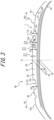
- a tire according to each example described in this specification includes a tread portion 90 ( FIG. 3 ), a pair of shoulder portions (not illustrated) extending inward in a tire radial direction from both ends of the tread portion 90 in a tire width direction, and a pair of bead portions (not illustrated) connected inward in the tire radial direction from the pair of shoulder portions.
- the tire according to each example described in this specification may have any internal configuration.
- the tire according to each example described in this specification may, for example, include a pair of bead cores (not illustrated) provided at the pair of bead portions, a pair of bead fillers (not illustrated) located outside the bead cores in the tire radial direction, a carcass 70 ( FIG. 3 ), a belt 60 ( FIG. 3 ), and tread rubber 80 ( FIG. 3 ).
- the carcass 70 extends in a toroidal shape between the pair of bead cores.
- the carcass 70 includes at least one layer (one layer in the example of the drawing) of carcass ply.
- the carcass ply of the carcass 70 can, for example, be constituted of cords made of steel, organic fibers, or the like coated with rubber.
- the carcass 70 can, for example, include a body portion extending in a toroidal shape between the pair of bead cores, and a pair of turn-up portions turned up outward in the tire width direction around the bead cores from an innermost end of the body portion in the tire radial direction at each of both sides relative to a tire equatorial plane CL.
- the belt 60 is positioned, in the tread portion 90, outside in the tire radial direction relative to a crown region of the carcass 70 ( FIG. 3 ).
- the belt 60 is constituted of at least one belt layer 61 (two layers in the example of the drawing).
- the belt layer 61 can be, for example, constituted of cords made of steel, organic fibers, or the like covered by rubber.
- the tread rubber 80 is disposed outside the belt 60 in the tire radial direction.
- FIGS. 1 to 4 A tire according to an embodiment of the present invention will be described with reference to FIGS. 1 to 4 .
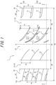
- FIG. 1 is a development view of a tread surface 1 of the tire according to the embodiment of the present invention, as developed on a flat surface.
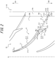
- FIG. 2 is an enlarged view of a part of FIG. 1 .
- FIG. 3 is a cross-sectional view in a tire width direction, illustrating a portion of the tire of FIG. 1 in cross-section along the line A-A of FIG. 1 .
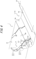
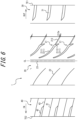
- FIG. 4 is a perspective view illustrating a part of the tire of FIG. 1 with enlargement.
- the tire according to an example of FIG. 1 is a tire whose mounting direction to a vehicle is specified.
- the direction of the arrow OUT indicates a direction of outside (hereinafter referred to as “vehicle-mounted outside”) in a vehicle width direction when the tire is mounted on the vehicle.
- the direction of the arrow IN indicates a direction of inside (hereinafter referred to as “vehicle-mounted inside”) in the vehicle width direction when the tire is mounted on the vehicle.
- a tread pattern that is asymmetrical with respect to a tire equatorial plane CL is provided in the tread surface 1 of this tire.
- the tire according to each example described in this specification may be a tire whose mounting direction to a vehicle is not specified.
- a tread pattern of the tire according to each example described in this specification may be asymmetrical with respect to a tire equatorial plane CL or symmetrical with respect to the tire equatorial plane CL.
- first tire circumferential side (CD1) first tire circumferential side
- second tire circumferential side (CD2) second tire circumferential side
- read surface (1) means an outer circumferential surface over an entire circumference of the tire that comes into contact with a road surface when the tire mounted on a rim and filled with a specified internal pressure is rolled under a maximum load.
- ground contact edge (TE1, TE2) refers to an end of the tread surface (1) in the tire width direction.
- rim means a standard rim (Measuring Rim in ETRTO's STANDARDS MANUAL and Design Rim in TRA's YEAR BOOK) in an applicable size as described in or to be described in an industrial standard valid for regions where tires are produced and used, such as JATMA YEAR BOOK of the JATMA (The Japan Automobile Tyre Manufacturers Association, Inc.) in Japan, STANDARDS MANUAL of the ETRTO (The European Tyre and Rim Technical Organisation) in Europe, YEAR BOOK of TRA (The Tire and Rim Association, Inc.) in the United States, and the like (in other words, the above-described "rim” includes sizes that may be included in the aforementioned industrial standards in the future, as well as current sizes.
- specified internal pressure refers to an air pressure (maximum air pressure) corresponding to a maximum load capacity of a single wheel in the applicable size and ply rating described in the aforementioned JATMA YEAR BOOK or other industrial standards.
- the “specified internal pressure” refers to an air pressure (maximum air pressure) corresponding to a maximum load capacity specified for each vehicle on which the tire is mounted.
- Maximum load means a load corresponding to the maximum load capacity described above.
- the "standard condition” refers to a condition in which the tire is mounted on the rim, filled with the above specified internal pressure, and unloaded.
- the dimensions of each of the elements in the tread surface such as the grooves and the lands, the ground contact width (TW), and the like are measured on a development view of the tread surface.
- the tire according to each example described in this specification has at least two (in the example of FIG. 1 , only two) circumferential main grooves 10 on the tread surface 1, as illustrated in FIG. 1 .
- the tire according to each example described in this specification is provided with at least a first circumferential main groove 11 and a second circumferential main groove 12, as the circumferential main grooves 10.
- one or more intermediate land portions 20 are partitioned. That is, the intermediate land portion 20 is partitioned between the first and second circumferential main grooves 11 and 12.
- a first end land portion 30 is partitioned between the first circumferential main groove 11 and a first ground contact edge TE1.
- a second end land portion 40 is partitioned between the second circumferential main groove 12 and a second ground contact edge TE2.
- Each of the intermediate land portion 20, the first end land portion 30, and the second end land portion 40 is not divided by transverse grooves (excluding sipes) in a tire circumferential direction, but are continuous in the tire circumferential direction over the entire tire in the tire circumferential direction, i.e., rib-like land portions.
- the first circumferential main groove 11, the first ground contact edge TE1, and the first end land portion 30 are located on the vehicle-mounted outside (OUT side) with respect to the tire equatorial plane CL.
- the second circumferential main groove 12, the second ground contact edge TE2, and the second end land portion 40 are located on the vehicle-mounted inside (IN side) with respect to the tire equatorial plane CL.
- the intermediate land portion 20 is located on the tire equatorial plane CL.
- first ground contact edge TE1 and the first end land portion 30 may be located on the vehicle-mounted inside (IN side) with respect to the tire equatorial plane CL
- second ground contact edge TE2 and the second end land portion 40 may be located on the vehicle-mounted outside (OUT side).
- the first circumferential main groove 11 and the second circumferential main groove 12 may be located on either side with respect to the tire equatorial plane CL.
- the second circumferential main groove 12 may be located on the vehicle-mounted outside (OUT side) with respect to the tire equatorial plane CL
- the first circumferential main groove 11 may be located on the vehicle-mounted inside (IN side) with respect to the tire equatorial plane CL.
- the first and second circumferential main grooves 11 and 12 may be located on opposite sides to each other with respect to the tire equatorial plane CL, as in the example of FIG. 1 , or may be located on the same side as each other with respect to the tire equatorial plane CL.
- the intermediate land portion 20 may be located on the tire equatorial plane CL, as in the example of FIG. 1 , or may not be located on the tire equatorial plane CL.
- maximum values of the groove depths D1 ( FIG. 3 ) of the circumferential main grooves 10 (in the example of FIG. 1 , the first and second circumferential main grooves) provided in the tread surface 1 are 50% or less of the groove widths W2 ( FIG. 1 ) of the circumferential main grooves 10 (in the example of FIG. 1 , the first and second circumferential main grooves), respectively.
- the groove depths D1 ( FIG. 3 ) of the circumferential main grooves (in the example of FIG. 1 , the first and second circumferential main grooves) provided in the tread surface 1 are shallower than those of conventional general tires.
- a plurality of resonators 21 are formed in the intermediate land portion 20 partitioned between the first circumferential main groove 11 and the second circumferential main groove 12.
- Each resonator 21 has an auxiliary groove 211. It is preferable that the resonator 21 further have a branch groove 212. Both ends of the auxiliary groove 211 terminate within the intermediate land portion 20.
- the branch groove 212 extends so as to connect between the auxiliary groove 211 and the first circumferential main groove 11, and the groove cross-sectional area of the branch groove 212 is smaller than that of the auxiliary groove 211.
- each of the branch groove 212, the branch groove 212, and the like is measured in the "standard condition" described above along a virtual plane perpendicular to a groove width centerline of each of the grooves.
- the maximum values of the groove depths D1 ( FIG. 3 ) of the circumferential main grooves 10 (in the example of FIG. 1 , the first and second circumferential main grooves) provided in the tread surface 1 are 50% or less of the groove widths W2 ( FIG. 1 ) of the circumferential main grooves 10 (in the example of FIG. 1 , the first and second circumferential main grooves), respectively, that is, are shallower than those of conventional general tires.
- the thickness T1 ( FIG. 3 ) of the tread rubber 80 of the tire can be thinner than those of conventional general tires. This makes it possible to reduce the weight of the tire and the rolling resistance of the tire.
- each circumferential main groove 10 shallower, as described above, and thus making the thickness T1 ( FIG. 3 ) of the tread rubber 80 thinner, the rigidity of the tire increases and vibration is transmitted more easily, so that input from a road surface becomes stronger during rolling of the tire and noise (in particular, passing noise) tends to be generated more easily. Therefore, in the tire according to each example described in this specification, as described above, the resonators 21 are formed in the intermediate land portion 20 partitioned between the first and second circumferential main grooves 11 and 12. By forming the resonator 21, during rolling of the tire, air flowing in the first circumferential main groove 11 flows into the resonator 21, thereby dispersing a frequency and reducing noise.
- the maximum values of the groove depths D1 ( FIG. 3 ) of the circumferential main grooves 10 are more preferably 45% or less of the groove widths W2 ( FIG. 1 ) of the circumferential main grooves 10 (in the example of FIG. 1 , the first and second circumferential main grooves), respectively.
- the thickness T1 ( FIG. 3 ) of the tread rubber 80 can be made thinner, making it easier to reduce the tire weight and rolling resistance.
- the maximum value of the groove depth D1 ( FIG. 3 ) of each of the circumferential main grooves 10 is preferably 6.5 mm or less, and more preferably 6.0 mm or less.
- the maximum value of the groove depth D1 ( FIG. 3 ) of each of the circumferential main grooves 10 is preferably 80% or less of the thickness T1 ( FIG. 3 ) of the tread rubber 80, and more preferably 75% or less.
- minimum values of the groove depths D1 ( FIG. 3 ) of the circumferential main grooves 10 are preferably 20% or more of the groove widths W2 ( FIG. 1 ) of the circumferential main grooves 10 (in the example of FIG. 1 , the first and second circumferential main grooves), and more preferably 25% or more, respectively. This improves drainage.
- the minimum value of the groove depth D1 ( FIG. 3 ) of each of the circumferential main grooves 10 is preferably 5.0 mm or more, and more preferably 5.5 mm or more.
- the minimum value of the groove depth D1 ( FIG. 3 ) of each of the circumferential main grooves 10 is preferably 65% or more of the thickness T1 ( FIG. 3 ) of the tread rubber 80, and more preferably 75% or more.
- the groove depth D1 of each of the circumferential main grooves 10 may be constant along the tire circumferential direction or may vary along the tire circumferential direction.
- the groove width W2 ( FIG. 1 ) of each of the circumferential main grooves 10 is preferably 5% or more of the ground contact width TW. This improves drainage.
- each of the circumferential main grooves 10 is preferably 10 mm or more.
- the groove width W2 ( FIG. 1 ) of each of the circumferential main grooves 10 is preferably 15% or less of the ground contact width TW. This ensures sufficient rigidity.
- the acute angle-side inclination angle ⁇ 3 ( FIG. 2 ) at the end of the auxiliary groove 211 of the resonator 21, on the side far from the first circumferential main groove 11, with respect to the tire width direction is preferably 45° or more and 80° or less.
- the inclination angle ⁇ 3 may be the same as the inclination angle ⁇ 1.
- the acute angle-side inclination angle of the first auxiliary groove portion 2111 of the auxiliary groove 211 of the resonator 21 with respect to the tire width direction gradually increase, as being far from the first circumferential main groove 11.
- the first auxiliary groove portion 2111 of the auxiliary groove 211 of the resonator 21 be convexly curved to the second tire circumferential side CD2.
- the acute angle-side inclination angle of the first auxiliary groove portion 2111 of the auxiliary groove 211 of the resonator 21 with respect to the tire width direction may be constant and linearly extend along the tire width direction.
- the acute angle-side inclination angle ⁇ 4 ( FIG. 2 ) at the end of the first auxiliary groove portion 2111 of the auxiliary groove 211 of the resonator 21, on the side connecting to the second auxiliary groove portion 2112, with respect to the tire width direction is preferably 0.9 to 1.1 times the acute angle-side inclination angle ⁇ 2 ( FIG. 2 ) at the end of the branch groove 212 of the resonator 21, on the side far from the first circumferential main groove 11, with respect to the tire width direction.
- the length L1 of the first auxiliary groove portion 2111 of the auxiliary groove 211 of the resonator 21 is preferably 2.0 or more times the length L2 of the second auxiliary groove portion 2112 of the auxiliary groove 211 of the resonator 21. This allows the overall length of the auxiliary groove 211 (in particular, the length L1 of the first auxiliary groove portion 2111) to be lengthened, which thus increases the volume of the auxiliary groove 211 and improves the noise reduction performance of the resonator 21.
- the length L1 of the first auxiliary groove portion 2111 of the auxiliary groove 211 of the resonator 21 is preferably 8.0 or less times the length L2 of the second auxiliary groove portion 2112 of the auxiliary groove 211 of the resonator 21, and more preferably 7.0 or less times the length L2 of the second auxiliary groove portion 2112 of the auxiliary groove 211 of the resonator 21.
- the “length (L1) of the first auxiliary groove portion (2111)” refers to the length of the groove width centerline (211c) of the first auxiliary groove portion (2111).
- the “length (L2) of the second auxiliary groove portion (2112)” refers to the length of the groove width centerline (211c) of the second auxiliary groove portion (2112).
- the length L1 of the first auxiliary groove portion 2111 of the auxiliary groove 211 of the resonator 21 is preferably 10 to 40% of the ground contact width TW.
- the length of the auxiliary groove 211 (in particular, the length L1 of the first auxiliary groove portion 2111) can be lengthened and rigidity can be enhanced.
- the length L1 of the first auxiliary groove portion 2111 of the auxiliary groove 211 of the resonator 21 is preferably 15 to 40 mm.
- the length L3 of the branch groove 212 of the resonator 21 is preferably 1 to 30% of the ground contact width TW.
- the volume of the auxiliary groove 211 of the resonator 21 is preferably 150 to 500 mm 3 .
- the branch groove 212 of the resonator 21 is preferably connected to a connecting portion between the first auxiliary groove portion 2111 and the second auxiliary groove portion 2112 in the auxiliary groove 211 of the resonator 21.
- branch groove 212 of the resonator 21 may be connected to any portion of the auxiliary groove 211 of the resonator 21.
- the branch groove 212 is preferably connected to the end of the first auxiliary groove portion 2111 on the side close to the first circumferential main groove 11.
- the branch groove 212 of the resonator 21 preferably includes a tread surface-side sipe portion 2121, which is open to the tread surface 1 and extends inward in the tire radial direction, and a tunnel portion 2122, which extends continuously from the tread surface-side sipe portion 2121 inward in the tire radial direction and has a larger groove width than the tread surface-side sipe portion 2121.
- the branch groove 212 Since the branch groove 212 has the tread surface-side sipe portion 2121 outside in the tire radial direction, the block portion 20b partitioned between the pair of branch grooves 212 adjacent in the tire circumferential direction, of the intermediate land portion 20, is prevented from collapsing when the tire is rolling. Since the branch groove 212 has the tunnel portion 2122 inside in the tire radial direction, it is possible to provide a passage of air to the resonator 21 and thus improve the noise reduction performance of the resonator 21.
- groove walls 10a of each of the circumferential main grooves 10 are preferably convexly curved inward in the tire radial direction and outward in the groove width direction.
- the groove walls 10a of each of the circumferential main grooves 10 are rounded.
- the branch groove 212 deeper, wear of the tread portion 90 (in particular, the block portion 20b of the intermediate land portion 20) can be reduced.
- the rigidity of the tread portion 90 tends to increase. Therefore, forming the branch grooves 212 deeper, in this manner, can effectively reduce wear, while ensuring sufficient rigidity.
- the opening extended portion 212a allows air in the first circumferential main groove 11 to easily get into the branch groove 212, which thus improves the noise reduction performance of the resonator 21. Therefore, noise can be further suppressed.
- outward in the groove width direction refers to a side far from the groove width centerline.
- the branch groove 212 (specifically, the opening extended portion 212a of the branch groove 212) preferably terminates at the vicinity of the boundary between the groove wall 10a and the groove bottom of the first circumferential main groove 11.
- the tunnel portion 2122 of the branch groove 212 of the resonator 21 is preferably open to the groove wall 10a (rounded groove wall 10a) of the first circumferential main groove 11.
- the pitch P1 ( FIG. 1 ) between the branch grooves 212 of the resonators 21 in the tire circumferential direction is preferably 5.0 or less times the groove depth D2 ( FIG. 3 ) the branch grooves 212.
- the intermediate land portion 20 is preferably provided with a plurality of intermediate land sipes 22 each of whose one end is open to the second circumferential main groove 12 and the other end terminates within the intermediate land portion 20. Thereby, wear of the tread portion 90 (in particular, the intermediate land portion 20) can be prevented.
- each of the intermediate land sipes 22 preferably extends gradually to the second tire circumferential side CD2, as being far from the second circumferential main groove 12.
- a pitch P2 ( FIG. 1 ) between the intermediate land sipes 22 in the tire circumferential direction is preferably 0.9 to 1.5 times the pitch P1 ( FIG. 1 ) between the branch grooves 212 of the resonators 21 in the tire circumferential direction.
- each of the first end land portion lug grooves 31 preferably extends gradually to the first tire circumferential side CD1, as being far from the first ground contact edge TE1.
- each of the first end land portion lug grooves 31 is preferably 1.5 to 4.5 mm, for example.
- a pitch P3 ( FIG. 1 ) between the first end land portion lug grooves 31 in the tire circumferential direction is preferably 0.4 to 1.0 times the pitch P1 ( FIG. 1 ) of the branch grooves 212 of the resonators 21 in the tire circumferential direction.
- the second end land portion 40 is preferably provided with a plurality of second end land portion lug grooves 42 each of whose one end is open to the second ground contact edge TE2 and the other end terminates within the second end land portion 40. This improves drainage while enhancing rigidity.
- a pitch P4 ( FIG. 1 ) between the second end land portion lug grooves 42 in the tire circumferential direction is preferably 0.4 to 1.0 times the pitch P1 ( FIG. 1 ) of the branch grooves 212 of the resonators 21 in the tire circumferential direction.
- the resonators 21 may be disposed on the tire equatorial plane CL.
- the resonators 21 may be disposed on both sides with respect to the tire equatorial plane CL.
- both ends of the auxiliary groove 211 terminate within the intermediate land portion 20
- the branch groove 212 extends so as to connect between the auxiliary groove 211 and the second circumferential main groove 12, and the branch groove 212 has a smaller groove cross-sectional area than the auxiliary groove 211.
- the intermediate land portion 20 is preferably located on the tire equatorial plane CL. This allows more effective reduction in noise.
- the intermediate land portion 20 may be provided with a narrow groove 23 on the tire equatorial plane CL. In this case, drainage can be improved.
- the negative ratio of the tread surface 1 is preferably 25 to 30%, and more preferably 25 to 29%.
- the "negative ratio of the tread surface (1)” means the ratio of the area of a part of the tread surface (1) that does not contact a road surface to the total area of the tread surface (1), when the tire is mounted on the rim, filled with an internal pressure of the tire of 250 kPa, and under a load of 4.17 kN applied to the tire.
- the "part of the tread surface (1) that does not contact a road surface” is constituted of various types of grooves and the like in the tread surface (1).
- the tire according to the present invention can be used as any type of pneumatic tire, but is suitably used as a pneumatic tire for passenger vehicles.
Landscapes
- Engineering & Computer Science (AREA)
- Mechanical Engineering (AREA)
- Tires In General (AREA)
Claims (14)
- Reifen, umfassend eine erste umlaufende Hauptrille (11) und eine zweite umlaufende Hauptrille (12) in einer Lauffläche (1),
wobeiein Resonator (21) in einem Zwischenstegabschnitt (20) ausgebildet ist, der zwischen der ersten umlaufenden Hauptrille (11) und der zweiten umlaufenden Hauptrille (12) aufgeteilt ist, undder Resonator (21) eine Nebenrille (211) umfasst, deren beiden Enden innerhalb des Zwischenstegabschnitts (20) enden, dadurch gekennzeichnet, dassRillentiefen D1 der ersten und der zweiten umlaufenden Hauptrille (11, 12) 50 % oder weniger von Rillenbreiten W2 der ersten bzw. der zweiten umlaufenden Hauptrille (11, 12) betragen unddie Rillenbreite W3 der Nebenrille (211) des Resonators (21) 80 % oder weniger der Rillentiefe D1 der ersten umlaufenden Hauptrille (11) beträgt. - Reifen nach Anspruch 1, wobei
die Nebenrille (211) des Resonators (21) Folgendes umfasst:einen ersten Nebenrillenabschnitt (2111), der sich zu einer ersten Reifenumfangsseite (CD1) erstreckt, während er sich allmählich von der ersten umlaufenden Hauptrille (11) entfernt; undeinen zweiten Nebenrillenabschnitt (2112), der von einem Ende des ersten Nebenrillenabschnitts (2111) auf einer Seite nahe der ersten umlaufenden Hauptrille (11) von beiden Enden des ersten Nebenrillenabschnitts (2111) in einer Erstreckungsrichtung durchgehend ist, wobei sich der zweite Nebenrillenabschnitt (2112) zu einer zweiten Reifenumfangsseite (CD2) erstreckt,ein Neigungswinkel θ6 auf der Seite des spitzen Winkels an einem Ende des zweiten Nebenrillenabschnitts (2112), auf einer Seite, die mit dem ersten Nebenrillenabschnitt (2111) verbunden ist, in Bezug auf eine Reifenbreitenrichtung größer ist als ein Neigungswinkel θ4 auf der Seite des spitzen Winkels an einem Ende des ersten Nebenrillenabschnitts (2111), auf einer Seite, die mit dem zweiten Nebenrillenabschnitt (2112) verbunden ist, in Bezug auf die Reifenbreitenrichtung, undeine Länge L1 des ersten Nebenrillenabschnitts (2111) der Nebenrille (211) des Resonators (21) das 2,0- bis 8,0-fache einer Länge L2 des zweiten Nebenrillenabschnitts (2112) der Nebenrille (211) des Resonators (21) beträgt. - Reifen nach Anspruch 2, wobei die Länge L1 des ersten Nebenrillenabschnitts (2111) der Nebenrille (211) des Resonators (21) 10 bis 40 % einer Bodenkontaktbreite TW des Reifens beträgt.
- Reifen nach einem der Ansprüche 1 bis 3, wobei die Rillentiefe D1 von jeder der ersten und der zweiten umlaufenden Nebenrille (11, 12) 6,5 mm oder weniger beträgt.
- Reifen nach einem der Ansprüche 1 bis 4, wobeider Resonator (21) ferner eine Zweigrille (212) umfasst, die sich derart erstreckt, dass sie eine Verbindung zwischen der Nebenrille (211) und der ersten umlaufenden Hauptrille (11) herstellt, wobei die Zweigrille (212) einen kleineren Rillenquerschnittsbereich aufweist als die Nebenrille (211), undeine Rillentiefe D2 der Zweigrille (212) des Resonators (21) 70 % oder mehr der Rillentiefe D1 der ersten umlaufenden Hauptrille (11) beträgt.
- Reifen nach einem der Ansprüche 1 bis 5, wobeider Resonator (21) ferner eine Zweigrille (212) umfasst, die sich derart erstreckt, dass sie eine Verbindung zwischen der Nebenrille (211) und der ersten umlaufenden Hauptrille (11) herstellt, wobei die Zweigrille (212) einen kleineren Rillenquerschnittsbereich aufweist als die Nebenrille (211), undein Neigungswinkel θ1 auf der Seite des spitzen Winkels an einem Ende der Zweigrille (212) des Resonators (21), auf einer Seite, die zur ersten umlaufenden Hauptrille (11) offen ist, mit Bezug auf eine Reifenbreitenrichtung 20 bis 60° beträgt.
- Reifen nach einem der Ansprüche 1 bis 6, wobeider Resonator (21) ferner eine Zweigrille (212) umfasst, die sich derart erstreckt, dass sie eine Verbindung zwischen der Nebenrille (211) und der ersten umlaufenden Hauptrille (11) herstellt, wobei die Zweigrille (212) einen kleineren Rillenquerschnittsbereich aufweist als die Nebenrille (211), undein Neigungswinkel θ3 auf der Seite des spitzen Winkels an einem Ende der Nebenrille (211) des Resonators (21), auf einer Seite, die von der ersten umlaufenden Hauptrille (11) entfernt ist, in Bezug auf eine Reifenbreitenrichtung größer ist als ein Neigungswinkel θ1 auf der Seite des spitzen Winkels an einem Ende der Zweigrille (212) des Resonators (21) auf einer Seite, die zu der ersten umlaufenden Hauptrille (11) offen ist, in Bezug auf die Reifenbreitenrichtung.
- Reifen nach einem der Ansprüche 1 bis 7, wobei
die Nebenrille (211) des Resonators (21) Folgendes umfasst:einen ersten Nebenrillenabschnitt (2111), der sich zu einer ersten Reifenumfangsseite (CD1) erstreckt, während er sich allmählich von der ersten umlaufenden Hauptrille (11) entfernt; undeinen zweiten Nebenrillenabschnitt (2112), der von einem Ende des ersten Nebenrillenabschnitts (2111) auf einer Seite nahe der ersten umlaufenden Hauptrille (11) durchgehend ist, wobei sich der zweite Nebenrillenabschnitt (2112) zu einer zweiten Reifenumfangsseite (CD2) erstreckt,ein Neigungswinkel θ6 auf der Seite des spitzen Winkels an einem Ende des zweiten Nebenrillenabschnitts (2112), auf einer Seite, die mit dem ersten Nebenrillenabschnitt (2111) verbunden ist, in Bezug auf eine Reifenbreitenrichtung größer ist als ein Neigungswinkel θ4 auf der Seite des spitzen Winkels an einem Ende des ersten Nebenrillenabschnitts (2111), auf einer Seite, die mit dem zweiten Nebenrillenabschnitt (2112) verbunden ist, in Bezug auf die Reifenbreitenrichtung. - Reifen nach Anspruch 8, wobei ein Neigungswinkel auf der Seite des spitzen Winkels des ersten Nebenrillenabschnitts (2111) der Nebenrille (211) des Resonators (21) in Bezug auf eine Reifenbreitenrichtung allmählich zunimmt, während er sich von der ersten umlaufenden Hauptrille (11) entfernt.
- Reifen nach Anspruch 8 oder 9, wobei eine Länge L1 des ersten Nebenrillenabschnitts (2111) der Nebenrille (211) des Resonators (21) das 2,0- bis 7,0-fache einer Länge L2 des zweiten Nebenrillenabschnitts (2112) der Nebenrille (211) des Resonators (21) beträgt.
- Reifen nach einem der Ansprüche 8 bis 10, wobeider Resonator (21) ferner eine Zweigrille (212) umfasst, die sich derart erstreckt, dass sie eine Verbindung zwischen der Nebenrille (211) und der ersten umlaufenden Hauptrille (11) herstellt, wobei die Zweigrille (212) einen kleineren Rillenquerschnittsbereich aufweist als die Nebenrille (211), unddie Zweigrille (212) des Resonators (21) mit einem Verbindungsabschnitt zwischen dem ersten Nebenrillenabschnitt (2111) und dem zweiten Nebenrillenabschnitt (2112) in der Nebenrille (211) des Resonators (21) verbunden ist.
- Reifen nach einem der Ansprüche 1 bis 11, wobeider Resonator (21) ferner eine Zweigrille (212) umfasst, die sich derart erstreckt, dass sie eine Verbindung zwischen der Nebenrille (211) und der ersten umlaufenden Hauptrille (11) herstellt, wobei die Zweigrille (212) einen kleineren Rillenquerschnittsbereich aufweist als die Nebenrille (211),eine Steigung P1 zwischen den Zweigrillen (212) der Resonatoren (21) in einer Reifenumfangsrichtung das 2,5- bis 5,0-fache einer Rillentiefe D2 der Zweigrille (212) beträgt.
- Reifen nach einem der Ansprüche 1 bis 12, wobeider Resonator (21) ferner eine Zweigrille (212) umfasst, die sich derart erstreckt, dass sie eine Verbindung zwischen der Nebenrille (211) und der ersten umlaufenden Hauptrille (11) herstellt, wobei die Zweigrille (212) einen kleineren Rillenquerschnittsbereich aufweist als die Nebenrille (211),die Zweigrille (212) des Resonators (21) Folgendes umfasst:einen Lamellenabschnitt (2121) auf der Laufflächenseite, der zu der Lauffläche (1) offen ist, wobei sich der Lamellenabschnitt (2121) auf der Lauchflächenseite nach innen in einer radialen Richtung des Reifens erstreckt; undeinen Tunnelabschnitt (2122), der sich durchgehend von dem Lamellenabschnitt (2121) auf der Laufflächenseite nach innen in der radialen Richtung des Reifens erstreckt, wobei der Tunnelabschnitt (2122) eine größere Rillenbreite aufweist als der Lamellenabschnitt (2121) auf der Laufflächenseite.
- Reifen nach einem der Ansprüche 1 bis 13, wobeider Resonator (21) ferner eine Zweigrille (212) umfasst, die sich derart erstreckt, dass sie eine Verbindung zwischen der Nebenrille (211) und der ersten umlaufenden Hauptrille (11) herstellt, wobei die Zweigrille (212) einen kleineren Rillenquerschnittsbereich aufweist als die Nebenrille (211),eine Rillenwand (10a) der ersten umlaufenden Hauptrille (11) in einer radialen Richtung des Reifens konvex nach innen und in einer Rillenbreitenrichtung nach außen gekrümmt ist, undsich die Zweigrille (212) des Resonators (21) zu der Rillenwand (10a) der ersten umlaufenden Hauptrille (11) erstreckt.
Applications Claiming Priority (3)
| Application Number | Priority Date | Filing Date | Title |
|---|---|---|---|
| JP2020082610A JP7365292B2 (ja) | 2020-05-08 | 2020-05-08 | タイヤ |
| JP2020082606A JP7365291B2 (ja) | 2020-05-08 | 2020-05-08 | タイヤ |
| PCT/JP2021/017414 WO2021225146A1 (ja) | 2020-05-08 | 2021-05-06 | タイヤ |
Publications (3)
| Publication Number | Publication Date |
|---|---|
| EP4147884A1 EP4147884A1 (de) | 2023-03-15 |
| EP4147884A4 EP4147884A4 (de) | 2023-11-22 |
| EP4147884B1 true EP4147884B1 (de) | 2025-07-02 |
Family
ID=78468025
Family Applications (1)
| Application Number | Title | Priority Date | Filing Date |
|---|---|---|---|
| EP21800963.7A Active EP4147884B1 (de) | 2020-05-08 | 2021-05-06 | Reifen |
Country Status (4)
| Country | Link |
|---|---|
| US (1) | US20230219375A1 (de) |
| EP (1) | EP4147884B1 (de) |
| CN (1) | CN115515802B (de) |
| WO (1) | WO2021225146A1 (de) |
Families Citing this family (3)
| Publication number | Priority date | Publication date | Assignee | Title |
|---|---|---|---|---|
| JP7697875B2 (ja) * | 2021-11-25 | 2025-06-24 | 株式会社ブリヂストン | 空気入りタイヤ |
| WO2023105877A1 (ja) * | 2021-12-10 | 2023-06-15 | 株式会社ブリヂストン | タイヤ |
| FR3136194A1 (fr) * | 2022-06-03 | 2023-12-08 | Compagnie Generale Des Etablissements Michelin | Pneumatique comprenant des couples de découpures transversales de dispersion sonore |
Family Cites Families (21)
| Publication number | Priority date | Publication date | Assignee | Title |
|---|---|---|---|---|
| JP5013731B2 (ja) * | 2006-03-31 | 2012-08-29 | 株式会社ブリヂストン | 空気入りタイヤ |
| JP5060790B2 (ja) * | 2007-01-25 | 2012-10-31 | 株式会社ブリヂストン | 空気入りタイヤ |
| KR101096965B1 (ko) * | 2007-02-19 | 2011-12-20 | 가부시키가이샤 브리지스톤 | 공기입 타이어 |
| JP4939979B2 (ja) * | 2007-03-01 | 2012-05-30 | 株式会社ブリヂストン | 空気入りタイヤ |
| JP4976214B2 (ja) * | 2007-06-22 | 2012-07-18 | 株式会社ブリヂストン | 空気入りタイヤ |
| JP5193549B2 (ja) * | 2007-10-04 | 2013-05-08 | 株式会社ブリヂストン | 空気入りタイヤ |
| JP5255520B2 (ja) * | 2009-05-28 | 2013-08-07 | 株式会社ブリヂストン | 空気入りタイヤ |
| JP5475476B2 (ja) * | 2010-01-07 | 2014-04-16 | 株式会社ブリヂストン | 空気入りタイヤ |
| JP5426410B2 (ja) * | 2010-01-18 | 2014-02-26 | 株式会社ブリヂストン | 空気入りタイヤ |
| JP5711997B2 (ja) * | 2011-02-24 | 2015-05-07 | 株式会社ブリヂストン | タイヤ |
| JP2013180590A (ja) * | 2012-02-29 | 2013-09-12 | Bridgestone Corp | タイヤ |
| JP6043237B2 (ja) * | 2013-04-25 | 2016-12-14 | 株式会社ブリヂストン | 空気入りタイヤ |
| JP5507735B1 (ja) * | 2013-04-25 | 2014-05-28 | 株式会社ブリヂストン | 空気入りタイヤ |
| JP2015214303A (ja) * | 2014-05-13 | 2015-12-03 | 株式会社ブリヂストン | タイヤ |
| JP6001710B2 (ja) * | 2015-03-06 | 2016-10-05 | 株式会社ブリヂストン | 空気入りタイヤ |
| WO2019117091A1 (ja) * | 2017-12-13 | 2019-06-20 | 株式会社ブリヂストン | 空気入りタイヤ |
| JP2019111845A (ja) * | 2017-12-20 | 2019-07-11 | 株式会社ブリヂストン | 空気入りタイヤ |
| JP7091232B2 (ja) * | 2018-11-27 | 2022-06-27 | 株式会社ブリヂストン | タイヤ |
| JP2020082610A (ja) | 2018-11-29 | 2020-06-04 | ローランドディー.ジー.株式会社 | インクジェットプリンタ |
| JP2020082606A (ja) | 2018-11-29 | 2020-06-04 | 員丈 上平 | 積層造形による製造物および積層造形製造物の製造方法 |
| JP2023177703A (ja) * | 2022-06-02 | 2023-12-14 | 株式会社エフノート | 電子打楽器 |
-
2021
- 2021-05-06 EP EP21800963.7A patent/EP4147884B1/de active Active
- 2021-05-06 WO PCT/JP2021/017414 patent/WO2021225146A1/ja not_active Ceased
- 2021-05-06 CN CN202180033583.6A patent/CN115515802B/zh active Active
- 2021-05-06 US US17/996,933 patent/US20230219375A1/en active Pending
Also Published As
| Publication number | Publication date |
|---|---|
| WO2021225146A1 (ja) | 2021-11-11 |
| CN115515802B (zh) | 2024-04-19 |
| US20230219375A1 (en) | 2023-07-13 |
| EP4147884A1 (de) | 2023-03-15 |
| EP4147884A4 (de) | 2023-11-22 |
| CN115515802A (zh) | 2022-12-23 |
Similar Documents
| Publication | Publication Date | Title |
|---|---|---|
| EP2716477B1 (de) | Luftreifen | |
| EP4147884B1 (de) | Reifen | |
| JP2019137338A (ja) | 空気入りタイヤ | |
| US12454153B2 (en) | Tire | |
| EP4342690B1 (de) | Reifen | |
| EP4147883B1 (de) | Reifen | |
| CN114829163B (zh) | 轮胎 | |
| JP7365291B2 (ja) | タイヤ | |
| JP7365290B2 (ja) | タイヤ | |
| JP7365292B2 (ja) | タイヤ | |
| JP7405686B2 (ja) | タイヤ | |
| US12434510B2 (en) | Pneumatic radial tire for passenger vehicles | |
| US12409683B2 (en) | Pneumatic tire | |
| US20240408915A1 (en) | Pneumatic radial tire for passenger vehicles | |
| JP2025132487A (ja) | タイヤ | |
| CN120677073A (zh) | 轮胎 | |
| CN117615919A (zh) | 乘用车用充气子午线轮胎 | |
| CN117794750A (zh) | 乘用车用充气子午线轮胎 | |
| CN117693432A (zh) | 乘用车用充气子午线轮胎 | |
| CN117651650A (zh) | 乘用车用充气子午线轮胎 |
Legal Events
| Date | Code | Title | Description |
|---|---|---|---|
| STAA | Information on the status of an ep patent application or granted ep patent |
Free format text: STATUS: THE INTERNATIONAL PUBLICATION HAS BEEN MADE |
|
| PUAI | Public reference made under article 153(3) epc to a published international application that has entered the european phase |
Free format text: ORIGINAL CODE: 0009012 |
|
| STAA | Information on the status of an ep patent application or granted ep patent |
Free format text: STATUS: REQUEST FOR EXAMINATION WAS MADE |
|
| 17P | Request for examination filed |
Effective date: 20221207 |
|
| AK | Designated contracting states |
Kind code of ref document: A1 Designated state(s): AL AT BE BG CH CY CZ DE DK EE ES FI FR GB GR HR HU IE IS IT LI LT LU LV MC MK MT NL NO PL PT RO RS SE SI SK SM TR |
|
| DAV | Request for validation of the european patent (deleted) | ||
| DAX | Request for extension of the european patent (deleted) | ||
| A4 | Supplementary search report drawn up and despatched |
Effective date: 20231019 |
|
| RIC1 | Information provided on ipc code assigned before grant |
Ipc: B60C 5/00 20060101ALI20231013BHEP Ipc: B60C 11/04 20060101ALI20231013BHEP Ipc: B60C 11/13 20060101ALI20231013BHEP Ipc: B60C 11/12 20060101ALI20231013BHEP Ipc: B60C 11/03 20060101ALI20231013BHEP Ipc: B60C 11/00 20060101AFI20231013BHEP |
|
| GRAP | Despatch of communication of intention to grant a patent |
Free format text: ORIGINAL CODE: EPIDOSNIGR1 |
|
| STAA | Information on the status of an ep patent application or granted ep patent |
Free format text: STATUS: GRANT OF PATENT IS INTENDED |
|
| RIC1 | Information provided on ipc code assigned before grant |
Ipc: B60C 5/00 20060101ALI20241216BHEP Ipc: B60C 11/04 20060101ALI20241216BHEP Ipc: B60C 11/13 20060101ALI20241216BHEP Ipc: B60C 11/12 20060101ALI20241216BHEP Ipc: B60C 11/03 20060101ALI20241216BHEP Ipc: B60C 11/00 20060101AFI20241216BHEP |
|
| INTG | Intention to grant announced |
Effective date: 20250116 |
|
| GRAS | Grant fee paid |
Free format text: ORIGINAL CODE: EPIDOSNIGR3 |
|
| P01 | Opt-out of the competence of the unified patent court (upc) registered |
Free format text: CASE NUMBER: APP_16555/2025 Effective date: 20250404 |
|
| GRAA | (expected) grant |
Free format text: ORIGINAL CODE: 0009210 |
|
| STAA | Information on the status of an ep patent application or granted ep patent |
Free format text: STATUS: THE PATENT HAS BEEN GRANTED |
|
| AK | Designated contracting states |
Kind code of ref document: B1 Designated state(s): AL AT BE BG CH CY CZ DE DK EE ES FI FR GB GR HR HU IE IS IT LI LT LU LV MC MK MT NL NO PL PT RO RS SE SI SK SM TR |
|
| REG | Reference to a national code |
Ref country code: GB Ref legal event code: FG4D |
|
| REG | Reference to a national code |
Ref country code: CH Ref legal event code: EP |
|
| REG | Reference to a national code |
Ref country code: DE Ref legal event code: R096 Ref document number: 602021033473 Country of ref document: DE |
|
| REG | Reference to a national code |
Ref country code: IE Ref legal event code: FG4D |
|
| REG | Reference to a national code |
Ref country code: NL Ref legal event code: MP Effective date: 20250702 |
|
| PG25 | Lapsed in a contracting state [announced via postgrant information from national office to epo] |
Ref country code: PT Free format text: LAPSE BECAUSE OF FAILURE TO SUBMIT A TRANSLATION OF THE DESCRIPTION OR TO PAY THE FEE WITHIN THE PRESCRIBED TIME-LIMIT Effective date: 20251103 |
|
| PG25 | Lapsed in a contracting state [announced via postgrant information from national office to epo] |
Ref country code: NL Free format text: LAPSE BECAUSE OF FAILURE TO SUBMIT A TRANSLATION OF THE DESCRIPTION OR TO PAY THE FEE WITHIN THE PRESCRIBED TIME-LIMIT Effective date: 20250702 |
|
| REG | Reference to a national code |
Ref country code: AT Ref legal event code: MK05 Ref document number: 1808841 Country of ref document: AT Kind code of ref document: T Effective date: 20250702 |
|
| PG25 | Lapsed in a contracting state [announced via postgrant information from national office to epo] |
Ref country code: IS Free format text: LAPSE BECAUSE OF FAILURE TO SUBMIT A TRANSLATION OF THE DESCRIPTION OR TO PAY THE FEE WITHIN THE PRESCRIBED TIME-LIMIT Effective date: 20251102 |
|
| PG25 | Lapsed in a contracting state [announced via postgrant information from national office to epo] |
Ref country code: NO Free format text: LAPSE BECAUSE OF FAILURE TO SUBMIT A TRANSLATION OF THE DESCRIPTION OR TO PAY THE FEE WITHIN THE PRESCRIBED TIME-LIMIT Effective date: 20251002 |
|
| REG | Reference to a national code |
Ref country code: LT Ref legal event code: MG9D |
|
| PG25 | Lapsed in a contracting state [announced via postgrant information from national office to epo] |
Ref country code: AT Free format text: LAPSE BECAUSE OF FAILURE TO SUBMIT A TRANSLATION OF THE DESCRIPTION OR TO PAY THE FEE WITHIN THE PRESCRIBED TIME-LIMIT Effective date: 20250702 |
|
| PG25 | Lapsed in a contracting state [announced via postgrant information from national office to epo] |
Ref country code: FI Free format text: LAPSE BECAUSE OF FAILURE TO SUBMIT A TRANSLATION OF THE DESCRIPTION OR TO PAY THE FEE WITHIN THE PRESCRIBED TIME-LIMIT Effective date: 20250702 |
|
| PG25 | Lapsed in a contracting state [announced via postgrant information from national office to epo] |
Ref country code: HR Free format text: LAPSE BECAUSE OF FAILURE TO SUBMIT A TRANSLATION OF THE DESCRIPTION OR TO PAY THE FEE WITHIN THE PRESCRIBED TIME-LIMIT Effective date: 20250702 |
|
| PG25 | Lapsed in a contracting state [announced via postgrant information from national office to epo] |
Ref country code: GR Free format text: LAPSE BECAUSE OF FAILURE TO SUBMIT A TRANSLATION OF THE DESCRIPTION OR TO PAY THE FEE WITHIN THE PRESCRIBED TIME-LIMIT Effective date: 20251003 |
|
| PG25 | Lapsed in a contracting state [announced via postgrant information from national office to epo] |
Ref country code: CZ Free format text: LAPSE BECAUSE OF FAILURE TO SUBMIT A TRANSLATION OF THE DESCRIPTION OR TO PAY THE FEE WITHIN THE PRESCRIBED TIME-LIMIT Effective date: 20250702 Ref country code: SE Free format text: LAPSE BECAUSE OF FAILURE TO SUBMIT A TRANSLATION OF THE DESCRIPTION OR TO PAY THE FEE WITHIN THE PRESCRIBED TIME-LIMIT Effective date: 20250702 |
|
| PG25 | Lapsed in a contracting state [announced via postgrant information from national office to epo] |
Ref country code: LV Free format text: LAPSE BECAUSE OF FAILURE TO SUBMIT A TRANSLATION OF THE DESCRIPTION OR TO PAY THE FEE WITHIN THE PRESCRIBED TIME-LIMIT Effective date: 20250702 |
|
| PG25 | Lapsed in a contracting state [announced via postgrant information from national office to epo] |
Ref country code: PL Free format text: LAPSE BECAUSE OF FAILURE TO SUBMIT A TRANSLATION OF THE DESCRIPTION OR TO PAY THE FEE WITHIN THE PRESCRIBED TIME-LIMIT Effective date: 20250702 Ref country code: BG Free format text: LAPSE BECAUSE OF FAILURE TO SUBMIT A TRANSLATION OF THE DESCRIPTION OR TO PAY THE FEE WITHIN THE PRESCRIBED TIME-LIMIT Effective date: 20250702 |
|
| PG25 | Lapsed in a contracting state [announced via postgrant information from national office to epo] |
Ref country code: RS Free format text: LAPSE BECAUSE OF FAILURE TO SUBMIT A TRANSLATION OF THE DESCRIPTION OR TO PAY THE FEE WITHIN THE PRESCRIBED TIME-LIMIT Effective date: 20251002 |
|
| PG25 | Lapsed in a contracting state [announced via postgrant information from national office to epo] |
Ref country code: ES Free format text: LAPSE BECAUSE OF FAILURE TO SUBMIT A TRANSLATION OF THE DESCRIPTION OR TO PAY THE FEE WITHIN THE PRESCRIBED TIME-LIMIT Effective date: 20250702 |