EP4147883B1 - Reifen - Google Patents
Reifen Download PDFInfo
- Publication number
- EP4147883B1 EP4147883B1 EP21800670.8A EP21800670A EP4147883B1 EP 4147883 B1 EP4147883 B1 EP 4147883B1 EP 21800670 A EP21800670 A EP 21800670A EP 4147883 B1 EP4147883 B1 EP 4147883B1
- Authority
- EP
- European Patent Office
- Prior art keywords
- groove
- tire
- circumferential main
- resonator
- auxiliary
- Prior art date
- Legal status (The legal status is an assumption and is not a legal conclusion. Google has not performed a legal analysis and makes no representation as to the accuracy of the status listed.)
- Active
Links
Images


Classifications
-
- B—PERFORMING OPERATIONS; TRANSPORTING
- B60—VEHICLES IN GENERAL
- B60C—VEHICLE TYRES; TYRE INFLATION; TYRE CHANGING; CONNECTING VALVES TO INFLATABLE ELASTIC BODIES IN GENERAL; DEVICES OR ARRANGEMENTS RELATED TO TYRES
- B60C11/00—Tyre tread bands; Tread patterns; Anti-skid inserts
- B60C11/03—Tread patterns
- B60C11/13—Tread patterns characterised by the groove cross-section, e.g. for buttressing or preventing stone-trapping
-
- B—PERFORMING OPERATIONS; TRANSPORTING
- B60—VEHICLES IN GENERAL
- B60C—VEHICLE TYRES; TYRE INFLATION; TYRE CHANGING; CONNECTING VALVES TO INFLATABLE ELASTIC BODIES IN GENERAL; DEVICES OR ARRANGEMENTS RELATED TO TYRES
- B60C11/00—Tyre tread bands; Tread patterns; Anti-skid inserts
- B60C11/03—Tread patterns
- B60C11/0302—Tread patterns directional pattern, i.e. with main rolling direction
-
- B—PERFORMING OPERATIONS; TRANSPORTING
- B60—VEHICLES IN GENERAL
- B60C—VEHICLE TYRES; TYRE INFLATION; TYRE CHANGING; CONNECTING VALVES TO INFLATABLE ELASTIC BODIES IN GENERAL; DEVICES OR ARRANGEMENTS RELATED TO TYRES
- B60C11/00—Tyre tread bands; Tread patterns; Anti-skid inserts
- B60C11/03—Tread patterns
- B60C11/0304—Asymmetric patterns
-
- B—PERFORMING OPERATIONS; TRANSPORTING
- B60—VEHICLES IN GENERAL
- B60C—VEHICLE TYRES; TYRE INFLATION; TYRE CHANGING; CONNECTING VALVES TO INFLATABLE ELASTIC BODIES IN GENERAL; DEVICES OR ARRANGEMENTS RELATED TO TYRES
- B60C11/00—Tyre tread bands; Tread patterns; Anti-skid inserts
- B60C11/03—Tread patterns
- B60C11/032—Patterns comprising isolated recesses
-
- B—PERFORMING OPERATIONS; TRANSPORTING
- B60—VEHICLES IN GENERAL
- B60C—VEHICLE TYRES; TYRE INFLATION; TYRE CHANGING; CONNECTING VALVES TO INFLATABLE ELASTIC BODIES IN GENERAL; DEVICES OR ARRANGEMENTS RELATED TO TYRES
- B60C11/00—Tyre tread bands; Tread patterns; Anti-skid inserts
- B60C11/03—Tread patterns
- B60C11/0327—Tread patterns characterised by special properties of the tread pattern
- B60C11/033—Tread patterns characterised by special properties of the tread pattern by the void or net-to-gross ratios of the patterns
-
- B—PERFORMING OPERATIONS; TRANSPORTING
- B60—VEHICLES IN GENERAL
- B60C—VEHICLE TYRES; TYRE INFLATION; TYRE CHANGING; CONNECTING VALVES TO INFLATABLE ELASTIC BODIES IN GENERAL; DEVICES OR ARRANGEMENTS RELATED TO TYRES
- B60C11/00—Tyre tread bands; Tread patterns; Anti-skid inserts
- B60C11/03—Tread patterns
- B60C11/04—Tread patterns in which the raised area of the pattern consists only of continuous circumferential ribs, e.g. zig-zag
-
- B—PERFORMING OPERATIONS; TRANSPORTING
- B60—VEHICLES IN GENERAL
- B60C—VEHICLE TYRES; TYRE INFLATION; TYRE CHANGING; CONNECTING VALVES TO INFLATABLE ELASTIC BODIES IN GENERAL; DEVICES OR ARRANGEMENTS RELATED TO TYRES
- B60C11/00—Tyre tread bands; Tread patterns; Anti-skid inserts
- B60C11/03—Tread patterns
- B60C11/12—Tread patterns characterised by the use of narrow slits or incisions, e.g. sipes
- B60C11/1204—Tread patterns characterised by the use of narrow slits or incisions, e.g. sipes with special shape of the sipe
- B60C11/1218—Three-dimensional shape with regard to depth and extending direction
-
- B—PERFORMING OPERATIONS; TRANSPORTING
- B60—VEHICLES IN GENERAL
- B60C—VEHICLE TYRES; TYRE INFLATION; TYRE CHANGING; CONNECTING VALVES TO INFLATABLE ELASTIC BODIES IN GENERAL; DEVICES OR ARRANGEMENTS RELATED TO TYRES
- B60C11/00—Tyre tread bands; Tread patterns; Anti-skid inserts
- B60C11/03—Tread patterns
- B60C11/12—Tread patterns characterised by the use of narrow slits or incisions, e.g. sipes
- B60C11/1236—Tread patterns characterised by the use of narrow slits or incisions, e.g. sipes with special arrangements in the tread pattern
-
- B—PERFORMING OPERATIONS; TRANSPORTING
- B60—VEHICLES IN GENERAL
- B60C—VEHICLE TYRES; TYRE INFLATION; TYRE CHANGING; CONNECTING VALVES TO INFLATABLE ELASTIC BODIES IN GENERAL; DEVICES OR ARRANGEMENTS RELATED TO TYRES
- B60C11/00—Tyre tread bands; Tread patterns; Anti-skid inserts
- B60C11/0008—Tyre tread bands; Tread patterns; Anti-skid inserts characterised by the tread rubber
- B60C2011/0016—Physical properties or dimensions
- B60C2011/0033—Thickness of the tread
-
- B—PERFORMING OPERATIONS; TRANSPORTING
- B60—VEHICLES IN GENERAL
- B60C—VEHICLE TYRES; TYRE INFLATION; TYRE CHANGING; CONNECTING VALVES TO INFLATABLE ELASTIC BODIES IN GENERAL; DEVICES OR ARRANGEMENTS RELATED TO TYRES
- B60C11/00—Tyre tread bands; Tread patterns; Anti-skid inserts
- B60C11/03—Tread patterns
- B60C2011/0337—Tread patterns characterised by particular design features of the pattern
- B60C2011/0339—Grooves
- B60C2011/0341—Circumferential grooves
- B60C2011/0344—Circumferential grooves provided at the equatorial plane
-
- B—PERFORMING OPERATIONS; TRANSPORTING
- B60—VEHICLES IN GENERAL
- B60C—VEHICLE TYRES; TYRE INFLATION; TYRE CHANGING; CONNECTING VALVES TO INFLATABLE ELASTIC BODIES IN GENERAL; DEVICES OR ARRANGEMENTS RELATED TO TYRES
- B60C11/00—Tyre tread bands; Tread patterns; Anti-skid inserts
- B60C11/03—Tread patterns
- B60C2011/0337—Tread patterns characterised by particular design features of the pattern
- B60C2011/0339—Grooves
- B60C2011/0341—Circumferential grooves
- B60C2011/0348—Narrow grooves, i.e. having a width of less than 4 mm
-
- B—PERFORMING OPERATIONS; TRANSPORTING
- B60—VEHICLES IN GENERAL
- B60C—VEHICLE TYRES; TYRE INFLATION; TYRE CHANGING; CONNECTING VALVES TO INFLATABLE ELASTIC BODIES IN GENERAL; DEVICES OR ARRANGEMENTS RELATED TO TYRES
- B60C11/00—Tyre tread bands; Tread patterns; Anti-skid inserts
- B60C11/03—Tread patterns
- B60C2011/0337—Tread patterns characterised by particular design features of the pattern
- B60C2011/0339—Grooves
- B60C2011/0341—Circumferential grooves
- B60C2011/0353—Circumferential grooves characterised by width
-
- B—PERFORMING OPERATIONS; TRANSPORTING
- B60—VEHICLES IN GENERAL
- B60C—VEHICLE TYRES; TYRE INFLATION; TYRE CHANGING; CONNECTING VALVES TO INFLATABLE ELASTIC BODIES IN GENERAL; DEVICES OR ARRANGEMENTS RELATED TO TYRES
- B60C11/00—Tyre tread bands; Tread patterns; Anti-skid inserts
- B60C11/03—Tread patterns
- B60C2011/0337—Tread patterns characterised by particular design features of the pattern
- B60C2011/0339—Grooves
- B60C2011/0341—Circumferential grooves
- B60C2011/0355—Circumferential grooves characterised by depth
-
- B—PERFORMING OPERATIONS; TRANSPORTING
- B60—VEHICLES IN GENERAL
- B60C—VEHICLE TYRES; TYRE INFLATION; TYRE CHANGING; CONNECTING VALVES TO INFLATABLE ELASTIC BODIES IN GENERAL; DEVICES OR ARRANGEMENTS RELATED TO TYRES
- B60C11/00—Tyre tread bands; Tread patterns; Anti-skid inserts
- B60C11/03—Tread patterns
- B60C2011/0337—Tread patterns characterised by particular design features of the pattern
- B60C2011/0339—Grooves
- B60C2011/0358—Lateral grooves, i.e. having an angle of 45 to 90 degees to the equatorial plane
- B60C2011/0365—Lateral grooves, i.e. having an angle of 45 to 90 degees to the equatorial plane characterised by width
-
- B—PERFORMING OPERATIONS; TRANSPORTING
- B60—VEHICLES IN GENERAL
- B60C—VEHICLE TYRES; TYRE INFLATION; TYRE CHANGING; CONNECTING VALVES TO INFLATABLE ELASTIC BODIES IN GENERAL; DEVICES OR ARRANGEMENTS RELATED TO TYRES
- B60C11/00—Tyre tread bands; Tread patterns; Anti-skid inserts
- B60C11/03—Tread patterns
- B60C2011/0337—Tread patterns characterised by particular design features of the pattern
- B60C2011/0339—Grooves
- B60C2011/0358—Lateral grooves, i.e. having an angle of 45 to 90 degees to the equatorial plane
- B60C2011/0367—Lateral grooves, i.e. having an angle of 45 to 90 degees to the equatorial plane characterised by depth
-
- B—PERFORMING OPERATIONS; TRANSPORTING
- B60—VEHICLES IN GENERAL
- B60C—VEHICLE TYRES; TYRE INFLATION; TYRE CHANGING; CONNECTING VALVES TO INFLATABLE ELASTIC BODIES IN GENERAL; DEVICES OR ARRANGEMENTS RELATED TO TYRES
- B60C11/00—Tyre tread bands; Tread patterns; Anti-skid inserts
- B60C11/03—Tread patterns
- B60C2011/0337—Tread patterns characterised by particular design features of the pattern
- B60C2011/0339—Grooves
- B60C2011/0358—Lateral grooves, i.e. having an angle of 45 to 90 degees to the equatorial plane
- B60C2011/0372—Lateral grooves, i.e. having an angle of 45 to 90 degees to the equatorial plane with particular inclination angles
-
- B—PERFORMING OPERATIONS; TRANSPORTING
- B60—VEHICLES IN GENERAL
- B60C—VEHICLE TYRES; TYRE INFLATION; TYRE CHANGING; CONNECTING VALVES TO INFLATABLE ELASTIC BODIES IN GENERAL; DEVICES OR ARRANGEMENTS RELATED TO TYRES
- B60C11/00—Tyre tread bands; Tread patterns; Anti-skid inserts
- B60C11/03—Tread patterns
- B60C11/12—Tread patterns characterised by the use of narrow slits or incisions, e.g. sipes
- B60C11/1204—Tread patterns characterised by the use of narrow slits or incisions, e.g. sipes with special shape of the sipe
- B60C2011/1209—Tread patterns characterised by the use of narrow slits or incisions, e.g. sipes with special shape of the sipe straight at the tread surface
-
- B—PERFORMING OPERATIONS; TRANSPORTING
- B60—VEHICLES IN GENERAL
- B60C—VEHICLE TYRES; TYRE INFLATION; TYRE CHANGING; CONNECTING VALVES TO INFLATABLE ELASTIC BODIES IN GENERAL; DEVICES OR ARRANGEMENTS RELATED TO TYRES
- B60C11/00—Tyre tread bands; Tread patterns; Anti-skid inserts
- B60C11/03—Tread patterns
- B60C11/12—Tread patterns characterised by the use of narrow slits or incisions, e.g. sipes
- B60C2011/129—Sipe density, i.e. the distance between the sipes within the pattern
Definitions
- the present invention relates to a tire.
- a tire according to the present invention is a tire as claimed in claim 1.
- a tire according to the present invention can be used as any type of pneumatic tire, but is suitably used as a pneumatic tire for passenger vehicles.
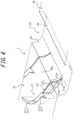
- a tire according to each example described in this specification includes a tread portion 90 ( FIG. 3 ), a pair of shoulder portions (not illustrated) extending inward in a tire radial direction from both ends of the tread portion 90 in a tire width direction, and a pair of bead portions (not illustrated) connected inward in the tire radial direction from the pair of shoulder portions.
- the tire according to each example described in this specification may be a tire whose mounting direction to a vehicle is not specified.
- a tread pattern of the tire according to each example described in this specification may be asymmetrical with respect to a tire equatorial plane CL or symmetrical with respect to the tire equatorial plane CL.
- first tire circumferential side (CD1) first tire circumferential side
- second tire circumferential side (CD2) second tire circumferential side
- ground contact edge (TE1, TE2) refers to an end of the tread surface (1) in the tire width direction.
- the "standard condition” refers to a condition in which the tire is mounted on the rim, filled with the above specified internal pressure, and unloaded.
- the dimensions of each of the elements in the tread surface such as the grooves and the lands, the ground contact width (TW), and the like are measured on a development view of the tread surface.
- the tire according to each example described in this specification has at least two (in the example of FIG. 1 , only two) circumferential main grooves 10 on the tread surface 1, as illustrated in FIG. 1 .
- the tire according to each example described in this specification is provided with at least a first circumferential main groove 11 and a second circumferential main groove 12, as the circumferential main grooves 10.
- one or more intermediate land portions 20 are partitioned. That is, the intermediate land portion 20 is partitioned between the first and second circumferential main grooves 11 and 12.
- first ground contact edge TE1 and the first end land portion 30 may be located on the vehicle-mounted inside (IN side) with respect to the tire equatorial plane CL
- second ground contact edge TE2 and the second end land portion 40 may be located on the vehicle-mounted outside (OUT side).
- the first circumferential main groove 11 and the second circumferential main groove 12 may be located on either side with respect to the tire equatorial plane CL.
- the second circumferential main groove 12 may be located on the vehicle-mounted outside (OUT side) with respect to the tire equatorial plane CL
- the first circumferential main groove 11 may be located on the vehicle-mounted inside (IN side) with respect to the tire equatorial plane CL.
- the groove depths D1 ( FIG. 3 ) of the circumferential main grooves (in the example of FIG. 1 , the first and second circumferential main grooves) provided in the tread surface 1 are shallower than those of conventional general tires.
- each of the branch groove 212, the branch groove 212, and the like is measured in the "standard condition" described above along a virtual plane perpendicular to a groove width centerline of each of the grooves.
- the maximum value of the groove depth D1 ( FIG. 3 ) of each of the circumferential main grooves 10 is preferably 80% or less of the thickness T1 ( FIG. 3 ) of the tread rubber 80, and more preferably 75% or less.
- minimum values of the groove depths D1 ( FIG. 3 ) of the circumferential main grooves 10 are preferably 20% or more of the groove widths W2 ( FIG. 1 ) of the circumferential main grooves 10 (in the example of FIG. 1 , the first and second circumferential main grooves), and more preferably 25% or more, respectively. This improves drainage.
- the minimum value of the groove depth D1 ( FIG. 3 ) of each of the circumferential main grooves 10 is preferably 5.0 mm or more, and more preferably 5.5 mm or more.
- the “maximum value of the groove depth (D1) of each of the circumferential main grooves (10)” refers to a groove depth (D1) at a portion at which the groove depth (D1) of each of the circumferential main grooves (10) is maximized.
- the “minimum value of the groove depth (D1) of each of the circumferential main grooves (10)” refers to a groove depth (D1) at a portion at which the groove depth (D1) of each of the circumferential main grooves (10) is minimized.
- the rigidity of the tread portion 90 (in particular, the intermediate land portion 20) can be increased, thereby reduction in the rigidity of the tread portion 90 (in particular, the intermediate land portion 20), which is caused by the provision of the resonators 21 can be suppressed.
- the maximum value of the groove width W3 ( FIG. 2 ) of the auxiliary groove 211 of the resonator 21 is preferably 80% or less of the maximum value of the groove depth D1 ( FIG. 3 ) of the first circumferential main groove 11, and more preferably 60% or less of the maximum value of the groove depth D1 ( FIG. 3 ) of the first circumferential main groove 11.
- the maximum value of the groove width W3 ( FIG. 2 ) of the auxiliary groove 211 of the resonator 21 is preferably 15% or more of the maximum value of the groove depth D3 ( FIG. 3 ) of the auxiliary groove 211. This improves noise reduction performance of the resonator 21.
- the maximum value of the groove width W3 ( FIG. 2 ) of the auxiliary groove 211 of the resonator 21 is preferably 15% or more of the maximum value of the groove depth D1 ( FIG. 3 ) of the first circumferential main groove 11.
- the groove width W3 of the auxiliary groove 211 may vary along an extending direction of the auxiliary groove 211, as in the example of FIG. 2 , or may be constant along the extending direction of the auxiliary groove 211.
- the "maximum value of the groove width (W3) of the auxiliary groove (211)" refers to a groove width (W3) at a portion at which the groove width (W3) of the auxiliary groove (211) is maximized.
- a minimum value of the groove depth D3 ( FIG. 3 ) of the auxiliary groove 211 of the resonator 21 is preferably 5.0 mm or more, and more preferably 5.5 mm or more. Therefore, deepening the groove depth D3 of the auxiliary groove 211 increases the volume of the auxiliary groove 211, and thus improves the noise reduction performance of the resonator 21 (and thereby suppresses noise increase). This is particularly preferable in a case in which the groove width W3 ( FIG. 2 ) of the auxiliary groove 211 is narrowed as described above.
- the minimum value of the groove depth D3 ( FIG. 3 ) of the auxiliary groove 211 of the resonator 21 is preferably 70% or more of the maximum value of the groove depth D1 ( FIG. 3 ) of the first circumferential main groove 11.
- the maximum value of the groove depth D3 ( FIG. 3 ) of the auxiliary groove 211 of the resonator 21 is preferably 6.5 mm or less.
- the maximum value of the groove depth D3 ( FIG. 3 ) of the auxiliary groove 211 of the resonator 21 is preferably 100% or less of the maximum value of the groove depth D1 ( FIG. 3 ) of the first circumferential main groove 11.
- the groove depth D3 of the auxiliary groove 211 may be constant along the extending direction of the auxiliary groove 211, or may vary along the extending direction of the auxiliary groove 211.
- a minimum value of the groove depth D2 ( FIG. 3 ) of the branch groove 212 of the resonator 21 is preferably 70% or more of the groove depth D1 of the first circumferential main groove 11. Therefore, by deepening the groove depth D2 of the branch groove 212, wear of the tread portion 90 (in particular, a block portion 20b of the intermediate land portion 20) can be reduced.
- the rigidity of the tread portion 90 tends to increase. Therefore, deepening the groove depth D2 of the branch grooves 212 in this manner can effectively reduce wear, while ensuring sufficient rigidity.
- the maximum value of the groove depth D2 ( FIG. 3 ) of the branch groove 212 of the resonator 21 is preferably 100% or less of the groove depth D1 of the first circumferential main groove 11. This allows increase in rigidity.
- the groove depth D2 of the branch groove 212 may be constant along an extending direction of the branch groove 212, or may vary along the extending direction of the branch groove 212.
- the "minimum value of the groove depth (D2) of the branch groove (212)” refers to a groove depth (D2) at a portion at which the groove depth (D2) of the branch groove (212) is minimized.
- the “maximum value of the groove depth (D2) of the branch groove (212)” refers to a groove depth (D2) at a portion at which the groove depth (D2) of the branch groove (212) is maximized.
- the "extending direction of the branch groove (212)” is an extending direction of a groove width centerline of the branch groove (212).
- the auxiliary groove 211 of the resonator 21 may have a first auxiliary groove portion 2111, which extends to the first tire circumferential side CD1 as being gradually far from the first circumferential main groove 11, and a second auxiliary groove portion 2112, which is continuous from an end of the first auxiliary groove portion 2111 on a side close to the first circumferential main groove 11, of both ends of the first auxiliary groove portion 2111 in the extending direction, and extends to the second tire circumferential side CD2.
- an acute angle-side inclination angle ⁇ 6 FIG.
- the second auxiliary groove portion 2112 at an end of the second auxiliary groove portion 2112, on a side connecting to the first auxiliary groove portion 2111, with respect to the tire width direction is preferably larger than an acute angle-side inclination angle ⁇ 4 ( FIG. 2 ) at an end of the first auxiliary groove portion 2111, on a side connecting to the second auxiliary groove portion 2112, with respect to the tire width direction.
- the provision of the second auxiliary groove portion 2112, in addition to the first auxiliary groove portion 2111, in the auxiliary groove 211 makes it possible to increase in the overall length of the auxiliary groove 211. This allows the volume of the auxiliary groove 211 to be increased, which thus improves the noise reduction performance of the resonator 21.
- the second auxiliary groove portion 2112 can reduce compression rigidity.
- the second auxiliary groove portion 2112 preferably extends to the second tire circumferential side CD2, as being gradually close to the first circumferential main groove 11, as in the example in FIG. 2 .
- the second auxiliary groove portion 2112 may extend to the second tire circumferential side CD2 while extending in parallel with the first circumferential main groove 11, or the second auxiliary groove portion 2112 may extend to the second tire circumferential side CD2 as being gradually far from the first circumferential main groove 11.
- auxiliary groove 211 may have only the first auxiliary groove portion 2111, without having the second auxiliary groove portion 2112.
- the acute angle-side inclination angle ⁇ 6 ( FIG. 2 ) at an end of the second auxiliary groove portion 2112 of the auxiliary groove 211 of the resonator 21, on the side connecting to the first auxiliary groove portion 2111, with respect to the tire width direction is preferably 1.0 to 5.0 times the acute angle-side inclination angle ⁇ 4 ( FIG. 2 ) at the end of the first auxiliary groove portion 2111 of the auxiliary groove 211 of the resonator 21, on the side connecting to the second auxiliary groove portion 2112, with respect to the tire width direction.
- the groove width of the first auxiliary groove portion 2111 of the auxiliary groove 211 of the resonator 21 gradually decrease toward the first tire circumferential side CD1, as in the example of FIG. 1 .
- the groove width of the second auxiliary groove portion 2112 of the auxiliary groove 211 of the resonator 21 gradually decrease toward the second tire circumferential side CD2, as in the example of FIG. 1 .
- an acute angle-side inclination angle ⁇ 1 ( FIG. 2 ) at an end of the branch groove 212 of the resonator 21, on the side open to the first circumferential main groove 11 (more specifically, an end located at the boundary between the intermediate land portion 20 and the first circumferential main groove 11), with respect to the tire width direction is preferably 20° or more.
- an acute angle-side inclination angle ⁇ 2 ( FIG. 2 ) at an end of the branch groove 212 of the resonator 21, on a side far from the first circumferential main groove 11, with respect to the tire width direction is preferably 20° or more.
- the acute angle-side inclination angle ⁇ 2 ( FIG. 2 ) at the end of the branch groove 212 of the resonator 21, on the side far from the first circumferential main groove 11, with respect to the tire width direction is preferably 60° or less, and more preferably 45° or less.
- the acute angle-side inclination angle of the branch groove 212 of the resonator 21 with respect to the tire width direction may be constant along the tire width direction, as in the example of FIG. 2 , or the acute angle-side inclination angle with respect to the tire width direction may gradually increase, as being gradually far from the first circumferential main groove 11.
- an acute angle-side inclination angle ⁇ 3 ( FIG. 2 ) at an end of the auxiliary groove 211 of the resonator 21, on a side far from the first circumferential main groove 11, with respect to the tire width direction is preferably larger than the acute angle-side inclination angle ⁇ 1 ( FIG. 2 ) at the end of the branch groove 212 of the resonator 21, on the side open to the first circumferential main groove 11, with respect to the tire width direction.
- the acute angle-side inclination angle ⁇ 3 ( FIG. 2 ) at the end of the auxiliary groove 211 of the resonator 21, on the side far from the first circumferential main groove 11, with respect to the tire width direction is preferably 45° or more and 80° or less.
- the inclination angle ⁇ 3 may be the same as the inclination angle ⁇ 1.
- the acute angle-side inclination angle of the first auxiliary groove portion 2111 of the auxiliary groove 211 of the resonator 21 with respect to the tire width direction gradually increase, as being far from the first circumferential main groove 11.
- the first auxiliary groove portion 2111 of the auxiliary groove 211 of the resonator 21 be convexly curved to the second tire circumferential side CD2.
- the acute angle-side inclination angle of the first auxiliary groove portion 2111 of the auxiliary groove 211 of the resonator 21 with respect to the tire width direction may be constant and linearly extend along the tire width direction.
- the acute angle-side inclination angle ⁇ 4 ( FIG. 2 ) at the end of the first auxiliary groove portion 2111 of the auxiliary groove 211 of the resonator 21, on the side connecting to the second auxiliary groove portion 2112, with respect to the tire width direction is preferably 0.9 to 1.1 times the acute angle-side inclination angle ⁇ 2 ( FIG. 2 ) at the end of the branch groove 212 of the resonator 21, on the side far from the first circumferential main groove 11, with respect to the tire width direction.
- the length L1 of the first auxiliary groove portion 2111 of the auxiliary groove 211 of the resonator 21 is preferably 2.0 or more times the length L2 of the second auxiliary groove portion 2112 of the auxiliary groove 211 of the resonator 21. This allows the overall length of the auxiliary groove 211 (in particular, the length L1 of the first auxiliary groove portion 2111) to be lengthened, which thus increases the volume of the auxiliary groove 211 and improves the noise reduction performance of the resonator 21.
- the “length (L3) of the branch groove (212)” refers to the length of a groove width centerline of the branch groove (212).
- the branch groove 212 (specifically, the opening extended portion 212a of the branch groove 212) preferably terminates at the vicinity of the boundary between the groove wall 10a and the groove bottom of the first circumferential main groove 11.
- the second end land portion 40 is preferably further provided with a plurality of connecting sipes 43 each of which extends so as to connect between the second end land portion lug groove 42 and the second circumferential main groove 12.
- the resonators 21 may be disposed on both sides with respect to the tire equatorial plane CL.
- both ends of the auxiliary groove 211 terminate within the intermediate land portion 20
- the branch groove 212 extends so as to connect between the auxiliary groove 211 and the second circumferential main groove 12, and the branch groove 212 has a smaller groove cross-sectional area than the auxiliary groove 211.
Landscapes
- Engineering & Computer Science (AREA)
- Mechanical Engineering (AREA)
- Tires In General (AREA)
Claims (14)
- Reifen, umfassend eine erste umlaufende Hauptrille (11) und eine zweite umlaufende Hauptrille (12) in einer Lauffläche (1),
wobeiein Resonator (21) in einem Zwischenstegabschnitt (20) gebildet ist, der zwischen der ersten umlaufenden Hauptrille (11) und der zweiten umlaufenden Hauptrille (12) unterteilt ist,der Resonator (21) eine Hilfsrille (211) umfasst, deren beide Enden innerhalb des Zwischenstegabschnitts (20) enden,der Resonator (21) ferner eine Zweigrille (212) umfasst, die sich so erstreckt, dass sie die Hilfsrille (211) und die erste umlaufende Hauptrille (11) verbindet, wobei die Zweigrille (212) eine kleinere Rillenquerschnittsfläche als die Hilfsrille (211) aufweist,dadurch gekennzeichnet, dassRillentiefen D1 der ersten und der zweiten umlaufenden Hauptrille (11, 12) 50 % oder weniger von Rillenbreiten W2 der ersten bzw. der zweiten umlaufenden Hauptrille (11, 12) betragen,eine Rillentiefe D3 der Hilfsrille (211) des Resonators (21) 70 % oder mehr der Rillentiefe D1 der ersten umlaufenden Hauptrille (11) beträgt,
undeine Steigung P1 zwischen den Zweigrillen (212) der Resonatoren (21) in einer Umfangsrichtung des Reifens das 2,5- bis 5,0-fache einer Rillentiefe D2 der Zweigrille (212) beträgt. - Reifen nach Anspruch 1, wobei
eine Rillentiefe D2 der Zweigrille (212) des Resonators (21) 70 % oder mehr der Rillentiefe D1 der ersten umlaufenden Hauptrille (11) beträgt. - Reifen nach Anspruch 1 oder 2, wobei
die Zweigrille (212) des Resonators (21) sich bis zur Rillenwand (10a) der ersten umlaufenden Hauptrille (11) erstreckt. - Reifen nach Anspruch 3, wobei die Rillenwand (10a) der ersten umlaufenden Hauptrille (11) in einer radialen Richtung des Reifens konkav nach innen und von einer Mittellinie der Rillenbreite der ersten umlaufenden Hauptrille (11) weg gekrümmt ist.
- Reifen nach Anspruch 3 oder 4, wobei die Zweigrille (212) des Resonators (21) in der Nähe einer Begrenzung zwischen der Rillenwand (10a) und einer Rillensohle der ersten umlaufenden Hauptrille (11) endet.
- Reifen nach einem der Ansprüche 1 bis 5, wobei
ein Neigungswinkel auf der Seite des spitzen Winkels θ1 an einem Ende der Zweigrille (212) des Resonators (21), auf einer Seite, die zur ersten umlaufenden Hauptrille (11) hin offen ist, in Bezug auf eine Reifenbreitenrichtung 20 bis 60° beträgt. - Reifen nach einem der Ansprüche 1 bis 6, wobei
ein Neigungswinkel auf der Seite des spitzen Winkels θ3 an einem Ende der Hilfsrille (211) des Resonators (21), auf einer Seite, die von der ersten umlaufenden Hauptrille (11) entfernt ist, in Bezug auf eine Reifenbreitenrichtung größer ist als ein Neigungswinkel auf der Seite des spitzen Winkels θ1 an einem Ende der Zweigrille (212) des Resonators (21), auf einer Seite, die zur ersten umlaufenden Hauptrille (11) hin offen ist, in Bezug auf die Reifenbreitenrichtung. - Reifen nach einem der Ansprüche 1 bis 7, wobei
die Hilfsrille (211) des Resonators (21) Folgendes umfasst:einen ersten Hilfsrillenabschnitt (2111), der sich zu einer ersten Umfangsseite (CD1) des Reifens erstreckt, während er sich allmählich von der ersten umlaufenden Hauptrille (11) entfernt; undeinen zweiten Hilfsrillenabschnitt (2112), der von einem Ende des ersten Hilfsrillenabschnitts (2111) auf einer Seite nahe der ersten umlaufenden Hauptrille (11) durchgehend ist, wobei sich der zweite Hilfsrillenabschnitt (2112) zu einer zweiten Umfangsseite (CD2) des Reifens erstreckt,ein Neigungswinkel auf der Seite des spitzen Winkels θ6 an einem Ende des zweiten Hilfsrillenabschnitts (2112), auf einer Seite, die mit dem ersten Hilfsrillenabschnitt (2111) verbunden ist, in Bezug auf eine Reifenbreitenrichtung größer ist als ein Neigungswinkel auf der Seite des spitzen Winkels θ4 an einem Ende des ersten Hilfsrillenabschnitts (2111), auf einer Seite, die mit dem zweiten Hilfsrillenabschnitt (2112) verbunden ist, in Bezug auf die Reifenbreitenrichtung. - Reifen nach Anspruch 8, wobei ein Neigungswinkel auf der Seite des spitzen Winkels des ersten Hilfsrillenabschnitts (2111) der Hilfsrille (211) des Resonators (21) in Bezug auf eine Reifenbreitenrichtung allmählich zunimmt, während er sich von der ersten umlaufenden Hauptrille (11) entfernt.
- Reifen nach Anspruch 8 oder 9, wobei eine Länge L1 des ersten Hilfsrillenabschnitts (2111) der Hilfsrille (211) des Resonators (21) das 2,0- bis 7,0-fache einer Länge L2 des zweiten Hilfsrillenabschnitts (2112) der Hilfsrille (211) des Resonators (21) beträgt.
- Reifen nach einem der Ansprüche 8 bis 10, wobei die Zweigrille (212) des Resonators (21) mit einem Verbindungsabschnitt zwischen dem ersten Hilfsrillenabschnitt (2111) und dem zweiten Hilfsrillenabschnitt (2112) in der Hilfsrille (211) des Resonators (21) verbunden ist.
- Reifen nach einem der Ansprüche 1 bis 11, wobei
die Zweigrille (212) des Resonators (21) Folgendes umfasst:einen laufflächenseitigen Lamellenabschnitt (2121), der zur Lauffläche (1) hin offen ist, wobei sich der laufflächenseitige Lamellenabschnitt (2121) in einer radialen Richtung des Reifens nach innen erstreckt; undeinen Tunnelabschnitt (2122), der sich in der radialen Richtung des Reifens durchgehend von dem laufflächenseitigen Lamellenabschnitt (2121) nach innen erstreckt, wobei der Tunnelabschnitt (2122) eine größere Rillenbreite als der laufflächenseitige Lamellenabschnitt (2121) aufweist. - Reifen nach einem der Ansprüche 1 bis 12, wobeieine Rillenwand (10a) der ersten umlaufenden Hauptrille (11) in einer radialen Richtung des Reifens konkav nach innen und von einer Mittellinie der Rillenbreite der ersten umlaufenden Hauptrille (11) weg gekrümmt ist, unddie Zweigrille (212) des Resonators (21) sich bis zur Rillenwand (10a) der ersten umlaufenden Hauptrille (11) erstreckt.
- Reifen nach Anspruch 12, wobei der Tunnelabschnitt (2122) der Zweigrille (212) des Resonators (21) zur Rillenwand (10a) der ersten umlaufenden Hauptrille (11) hin offen ist.
Applications Claiming Priority (3)
| Application Number | Priority Date | Filing Date | Title |
|---|---|---|---|
| JP2020082611A JP7405686B2 (ja) | 2020-05-08 | 2020-05-08 | タイヤ |
| JP2020082604A JP7365290B2 (ja) | 2020-05-08 | 2020-05-08 | タイヤ |
| PCT/JP2021/017413 WO2021225145A1 (ja) | 2020-05-08 | 2021-05-06 | タイヤ |
Publications (3)
| Publication Number | Publication Date |
|---|---|
| EP4147883A1 EP4147883A1 (de) | 2023-03-15 |
| EP4147883A4 EP4147883A4 (de) | 2023-11-22 |
| EP4147883B1 true EP4147883B1 (de) | 2025-07-02 |
Family
ID=78468026
Family Applications (1)
| Application Number | Title | Priority Date | Filing Date |
|---|---|---|---|
| EP21800670.8A Active EP4147883B1 (de) | 2020-05-08 | 2021-05-06 | Reifen |
Country Status (4)
| Country | Link |
|---|---|
| US (1) | US12472779B2 (de) |
| EP (1) | EP4147883B1 (de) |
| CN (1) | CN115515801B (de) |
| WO (1) | WO2021225145A1 (de) |
Families Citing this family (1)
| Publication number | Priority date | Publication date | Assignee | Title |
|---|---|---|---|---|
| WO2023105877A1 (ja) * | 2021-12-10 | 2023-06-15 | 株式会社ブリヂストン | タイヤ |
Family Cites Families (21)
| Publication number | Priority date | Publication date | Assignee | Title |
|---|---|---|---|---|
| JP5013731B2 (ja) * | 2006-03-31 | 2012-08-29 | 株式会社ブリヂストン | 空気入りタイヤ |
| JP5060790B2 (ja) * | 2007-01-25 | 2012-10-31 | 株式会社ブリヂストン | 空気入りタイヤ |
| JP4939979B2 (ja) * | 2007-03-01 | 2012-05-30 | 株式会社ブリヂストン | 空気入りタイヤ |
| KR101096965B1 (ko) * | 2007-02-19 | 2011-12-20 | 가부시키가이샤 브리지스톤 | 공기입 타이어 |
| JP4976214B2 (ja) | 2007-06-22 | 2012-07-18 | 株式会社ブリヂストン | 空気入りタイヤ |
| JP5193549B2 (ja) * | 2007-10-04 | 2013-05-08 | 株式会社ブリヂストン | 空気入りタイヤ |
| JP5255520B2 (ja) | 2009-05-28 | 2013-08-07 | 株式会社ブリヂストン | 空気入りタイヤ |
| JP5475476B2 (ja) * | 2010-01-07 | 2014-04-16 | 株式会社ブリヂストン | 空気入りタイヤ |
| JP5426410B2 (ja) * | 2010-01-18 | 2014-02-26 | 株式会社ブリヂストン | 空気入りタイヤ |
| JP5711997B2 (ja) * | 2011-02-24 | 2015-05-07 | 株式会社ブリヂストン | タイヤ |
| JP5307215B2 (ja) | 2011-10-19 | 2013-10-02 | 東洋ゴム工業株式会社 | 空気入りタイヤ |
| JP2013133084A (ja) | 2011-12-27 | 2013-07-08 | Bridgestone Corp | 空気入りタイヤ |
| JP5507735B1 (ja) | 2013-04-25 | 2014-05-28 | 株式会社ブリヂストン | 空気入りタイヤ |
| JP6043237B2 (ja) | 2013-04-25 | 2016-12-14 | 株式会社ブリヂストン | 空気入りタイヤ |
| JP2015214303A (ja) | 2014-05-13 | 2015-12-03 | 株式会社ブリヂストン | タイヤ |
| JP6344088B2 (ja) | 2014-06-25 | 2018-06-20 | 横浜ゴム株式会社 | 空気入りタイヤ |
| JP6001710B2 (ja) | 2015-03-06 | 2016-10-05 | 株式会社ブリヂストン | 空気入りタイヤ |
| WO2019117091A1 (ja) | 2017-12-13 | 2019-06-20 | 株式会社ブリヂストン | 空気入りタイヤ |
| JP7091232B2 (ja) * | 2018-11-27 | 2022-06-27 | 株式会社ブリヂストン | タイヤ |
| JP7192439B2 (ja) | 2018-11-29 | 2022-12-20 | 株式会社リコー | 液体を吐出する装置、印刷方法及び印刷画像の光沢度制御方法 |
| JP2020082604A (ja) | 2018-11-29 | 2020-06-04 | 京セラ株式会社 | 液体吐出ヘッドおよび記録装置 |
-
2021
- 2021-05-06 EP EP21800670.8A patent/EP4147883B1/de active Active
- 2021-05-06 CN CN202180033577.0A patent/CN115515801B/zh active Active
- 2021-05-06 WO PCT/JP2021/017413 patent/WO2021225145A1/ja not_active Ceased
- 2021-05-06 US US17/997,040 patent/US12472779B2/en active Active
Also Published As
| Publication number | Publication date |
|---|---|
| EP4147883A1 (de) | 2023-03-15 |
| US20230173850A1 (en) | 2023-06-08 |
| CN115515801A (zh) | 2022-12-23 |
| CN115515801B (zh) | 2024-11-26 |
| WO2021225145A1 (ja) | 2021-11-11 |
| EP4147883A4 (de) | 2023-11-22 |
| US12472779B2 (en) | 2025-11-18 |
Similar Documents
| Publication | Publication Date | Title |
|---|---|---|
| EP2716477B1 (de) | Luftreifen | |
| EP4147884B1 (de) | Reifen | |
| US12454153B2 (en) | Tire | |
| EP4342690B1 (de) | Reifen | |
| EP4147883B1 (de) | Reifen | |
| CN114829163B (zh) | 轮胎 | |
| JP7365291B2 (ja) | タイヤ | |
| JP7365290B2 (ja) | タイヤ | |
| JP7365292B2 (ja) | タイヤ | |
| JP7405686B2 (ja) | タイヤ | |
| US12434510B2 (en) | Pneumatic radial tire for passenger vehicles | |
| US12409683B2 (en) | Pneumatic tire | |
| US20240408915A1 (en) | Pneumatic radial tire for passenger vehicles | |
| JP2025132487A (ja) | タイヤ | |
| CN120677073A (zh) | 轮胎 | |
| JP2024099174A (ja) | 空気入りタイヤ | |
| CN117615919A (zh) | 乘用车用充气子午线轮胎 | |
| CN117794750A (zh) | 乘用车用充气子午线轮胎 | |
| CN117651650A (zh) | 乘用车用充气子午线轮胎 | |
| CN117693432A (zh) | 乘用车用充气子午线轮胎 |
Legal Events
| Date | Code | Title | Description |
|---|---|---|---|
| STAA | Information on the status of an ep patent application or granted ep patent |
Free format text: STATUS: THE INTERNATIONAL PUBLICATION HAS BEEN MADE |
|
| PUAI | Public reference made under article 153(3) epc to a published international application that has entered the european phase |
Free format text: ORIGINAL CODE: 0009012 |
|
| STAA | Information on the status of an ep patent application or granted ep patent |
Free format text: STATUS: REQUEST FOR EXAMINATION WAS MADE |
|
| 17P | Request for examination filed |
Effective date: 20221207 |
|
| AK | Designated contracting states |
Kind code of ref document: A1 Designated state(s): AL AT BE BG CH CY CZ DE DK EE ES FI FR GB GR HR HU IE IS IT LI LT LU LV MC MK MT NL NO PL PT RO RS SE SI SK SM TR |
|
| DAV | Request for validation of the european patent (deleted) | ||
| DAX | Request for extension of the european patent (deleted) | ||
| A4 | Supplementary search report drawn up and despatched |
Effective date: 20231019 |
|
| RIC1 | Information provided on ipc code assigned before grant |
Ipc: B60C 5/00 20060101ALI20231013BHEP Ipc: B60C 11/04 20060101ALI20231013BHEP Ipc: B60C 11/13 20060101ALI20231013BHEP Ipc: B60C 11/12 20060101ALI20231013BHEP Ipc: B60C 11/03 20060101ALI20231013BHEP Ipc: B60C 11/00 20060101AFI20231013BHEP |
|
| GRAP | Despatch of communication of intention to grant a patent |
Free format text: ORIGINAL CODE: EPIDOSNIGR1 |
|
| STAA | Information on the status of an ep patent application or granted ep patent |
Free format text: STATUS: GRANT OF PATENT IS INTENDED |
|
| RIC1 | Information provided on ipc code assigned before grant |
Ipc: B60C 5/00 20060101ALI20241216BHEP Ipc: B60C 11/04 20060101ALI20241216BHEP Ipc: B60C 11/13 20060101ALI20241216BHEP Ipc: B60C 11/12 20060101ALI20241216BHEP Ipc: B60C 11/03 20060101ALI20241216BHEP Ipc: B60C 11/00 20060101AFI20241216BHEP |
|
| INTG | Intention to grant announced |
Effective date: 20250116 |
|
| GRAS | Grant fee paid |
Free format text: ORIGINAL CODE: EPIDOSNIGR3 |
|
| P01 | Opt-out of the competence of the unified patent court (upc) registered |
Free format text: CASE NUMBER: APP_16574/2025 Effective date: 20250404 |
|
| GRAA | (expected) grant |
Free format text: ORIGINAL CODE: 0009210 |
|
| STAA | Information on the status of an ep patent application or granted ep patent |
Free format text: STATUS: THE PATENT HAS BEEN GRANTED |
|
| AK | Designated contracting states |
Kind code of ref document: B1 Designated state(s): AL AT BE BG CH CY CZ DE DK EE ES FI FR GB GR HR HU IE IS IT LI LT LU LV MC MK MT NL NO PL PT RO RS SE SI SK SM TR |
|
| REG | Reference to a national code |
Ref country code: GB Ref legal event code: FG4D |
|
| REG | Reference to a national code |
Ref country code: CH Ref legal event code: EP |
|
| REG | Reference to a national code |
Ref country code: DE Ref legal event code: R096 Ref document number: 602021033470 Country of ref document: DE |
|
| REG | Reference to a national code |
Ref country code: IE Ref legal event code: FG4D |
|
| REG | Reference to a national code |
Ref country code: NL Ref legal event code: MP Effective date: 20250702 |
|
| PG25 | Lapsed in a contracting state [announced via postgrant information from national office to epo] |
Ref country code: PT Free format text: LAPSE BECAUSE OF FAILURE TO SUBMIT A TRANSLATION OF THE DESCRIPTION OR TO PAY THE FEE WITHIN THE PRESCRIBED TIME-LIMIT Effective date: 20251103 |
|
| PG25 | Lapsed in a contracting state [announced via postgrant information from national office to epo] |
Ref country code: NL Free format text: LAPSE BECAUSE OF FAILURE TO SUBMIT A TRANSLATION OF THE DESCRIPTION OR TO PAY THE FEE WITHIN THE PRESCRIBED TIME-LIMIT Effective date: 20250702 |
|
| REG | Reference to a national code |
Ref country code: AT Ref legal event code: MK05 Ref document number: 1808840 Country of ref document: AT Kind code of ref document: T Effective date: 20250702 |
|
| PG25 | Lapsed in a contracting state [announced via postgrant information from national office to epo] |
Ref country code: IS Free format text: LAPSE BECAUSE OF FAILURE TO SUBMIT A TRANSLATION OF THE DESCRIPTION OR TO PAY THE FEE WITHIN THE PRESCRIBED TIME-LIMIT Effective date: 20251102 |
|
| PG25 | Lapsed in a contracting state [announced via postgrant information from national office to epo] |
Ref country code: NO Free format text: LAPSE BECAUSE OF FAILURE TO SUBMIT A TRANSLATION OF THE DESCRIPTION OR TO PAY THE FEE WITHIN THE PRESCRIBED TIME-LIMIT Effective date: 20251002 |
|
| REG | Reference to a national code |
Ref country code: LT Ref legal event code: MG9D |
|
| PG25 | Lapsed in a contracting state [announced via postgrant information from national office to epo] |
Ref country code: AT Free format text: LAPSE BECAUSE OF FAILURE TO SUBMIT A TRANSLATION OF THE DESCRIPTION OR TO PAY THE FEE WITHIN THE PRESCRIBED TIME-LIMIT Effective date: 20250702 |
|
| PG25 | Lapsed in a contracting state [announced via postgrant information from national office to epo] |
Ref country code: FI Free format text: LAPSE BECAUSE OF FAILURE TO SUBMIT A TRANSLATION OF THE DESCRIPTION OR TO PAY THE FEE WITHIN THE PRESCRIBED TIME-LIMIT Effective date: 20250702 |
|
| PG25 | Lapsed in a contracting state [announced via postgrant information from national office to epo] |
Ref country code: HR Free format text: LAPSE BECAUSE OF FAILURE TO SUBMIT A TRANSLATION OF THE DESCRIPTION OR TO PAY THE FEE WITHIN THE PRESCRIBED TIME-LIMIT Effective date: 20250702 |
|
| PG25 | Lapsed in a contracting state [announced via postgrant information from national office to epo] |
Ref country code: GR Free format text: LAPSE BECAUSE OF FAILURE TO SUBMIT A TRANSLATION OF THE DESCRIPTION OR TO PAY THE FEE WITHIN THE PRESCRIBED TIME-LIMIT Effective date: 20251003 |
|
| PG25 | Lapsed in a contracting state [announced via postgrant information from national office to epo] |
Ref country code: CZ Free format text: LAPSE BECAUSE OF FAILURE TO SUBMIT A TRANSLATION OF THE DESCRIPTION OR TO PAY THE FEE WITHIN THE PRESCRIBED TIME-LIMIT Effective date: 20250702 Ref country code: SE Free format text: LAPSE BECAUSE OF FAILURE TO SUBMIT A TRANSLATION OF THE DESCRIPTION OR TO PAY THE FEE WITHIN THE PRESCRIBED TIME-LIMIT Effective date: 20250702 |
|
| PG25 | Lapsed in a contracting state [announced via postgrant information from national office to epo] |
Ref country code: LV Free format text: LAPSE BECAUSE OF FAILURE TO SUBMIT A TRANSLATION OF THE DESCRIPTION OR TO PAY THE FEE WITHIN THE PRESCRIBED TIME-LIMIT Effective date: 20250702 |
|
| PG25 | Lapsed in a contracting state [announced via postgrant information from national office to epo] |
Ref country code: PL Free format text: LAPSE BECAUSE OF FAILURE TO SUBMIT A TRANSLATION OF THE DESCRIPTION OR TO PAY THE FEE WITHIN THE PRESCRIBED TIME-LIMIT Effective date: 20250702 Ref country code: BG Free format text: LAPSE BECAUSE OF FAILURE TO SUBMIT A TRANSLATION OF THE DESCRIPTION OR TO PAY THE FEE WITHIN THE PRESCRIBED TIME-LIMIT Effective date: 20250702 |
|
| PG25 | Lapsed in a contracting state [announced via postgrant information from national office to epo] |
Ref country code: RS Free format text: LAPSE BECAUSE OF FAILURE TO SUBMIT A TRANSLATION OF THE DESCRIPTION OR TO PAY THE FEE WITHIN THE PRESCRIBED TIME-LIMIT Effective date: 20251002 |
|
| PG25 | Lapsed in a contracting state [announced via postgrant information from national office to epo] |
Ref country code: ES Free format text: LAPSE BECAUSE OF FAILURE TO SUBMIT A TRANSLATION OF THE DESCRIPTION OR TO PAY THE FEE WITHIN THE PRESCRIBED TIME-LIMIT Effective date: 20250702 |