EP4145485B1 - Gleichstromschütz und fahrzeug - Google Patents
Gleichstromschütz und fahrzeug Download PDFInfo
- Publication number
- EP4145485B1 EP4145485B1 EP21829112.8A EP21829112A EP4145485B1 EP 4145485 B1 EP4145485 B1 EP 4145485B1 EP 21829112 A EP21829112 A EP 21829112A EP 4145485 B1 EP4145485 B1 EP 4145485B1
- Authority
- EP
- European Patent Office
- Prior art keywords
- magnet
- moving
- arc
- contact
- direct current
- Prior art date
- Legal status (The legal status is an assumption and is not a legal conclusion. Google has not performed a legal analysis and makes no representation as to the accuracy of the status listed.)
- Active
Links
Images


Classifications
-
- H—ELECTRICITY
- H01—ELECTRIC ELEMENTS
- H01H—ELECTRIC SWITCHES; RELAYS; SELECTORS; EMERGENCY PROTECTIVE DEVICES
- H01H73/00—Protective overload circuit-breaking switches in which excess current opens the contacts by automatic release of mechanical energy stored by previous operation of a hand reset mechanism
- H01H73/02—Details
- H01H73/18—Means for extinguishing or suppressing arc
-
- H—ELECTRICITY
- H01—ELECTRIC ELEMENTS
- H01H—ELECTRIC SWITCHES; RELAYS; SELECTORS; EMERGENCY PROTECTIVE DEVICES
- H01H50/00—Details of electromagnetic relays
- H01H50/54—Contact arrangements
-
- B—PERFORMING OPERATIONS; TRANSPORTING
- B60—VEHICLES IN GENERAL
- B60L—PROPULSION OF ELECTRICALLY-PROPELLED VEHICLES; SUPPLYING ELECTRIC POWER FOR AUXILIARY EQUIPMENT OF ELECTRICALLY-PROPELLED VEHICLES; ELECTRODYNAMIC BRAKE SYSTEMS FOR VEHICLES IN GENERAL; MAGNETIC SUSPENSION OR LEVITATION FOR VEHICLES; MONITORING OPERATING VARIABLES OF ELECTRICALLY-PROPELLED VEHICLES; ELECTRIC SAFETY DEVICES FOR ELECTRICALLY-PROPELLED VEHICLES
- B60L53/00—Methods of charging batteries, specially adapted for electric vehicles; Charging stations or on-board charging equipment therefor; Exchange of energy storage elements in electric vehicles
-
- B—PERFORMING OPERATIONS; TRANSPORTING
- B60—VEHICLES IN GENERAL
- B60R—VEHICLES, VEHICLE FITTINGS, OR VEHICLE PARTS, NOT OTHERWISE PROVIDED FOR
- B60R16/00—Electric or fluid circuits specially adapted for vehicles and not otherwise provided for; Arrangement of elements of electric or fluid circuits specially adapted for vehicles and not otherwise provided for
- B60R16/02—Electric or fluid circuits specially adapted for vehicles and not otherwise provided for; Arrangement of elements of electric or fluid circuits specially adapted for vehicles and not otherwise provided for electric constitutive elements
-
- H—ELECTRICITY
- H01—ELECTRIC ELEMENTS
- H01H—ELECTRIC SWITCHES; RELAYS; SELECTORS; EMERGENCY PROTECTIVE DEVICES
- H01H50/00—Details of electromagnetic relays
- H01H50/02—Bases; Casings; Covers
-
- H—ELECTRICITY
- H01—ELECTRIC ELEMENTS
- H01H—ELECTRIC SWITCHES; RELAYS; SELECTORS; EMERGENCY PROTECTIVE DEVICES
- H01H50/00—Details of electromagnetic relays
- H01H50/02—Bases; Casings; Covers
- H01H50/04—Mounting complete relay or separate parts of relay on a base or inside a case
- H01H50/041—Details concerning assembly of relays
- H01H50/045—Details particular to contactors
-
- H—ELECTRICITY
- H01—ELECTRIC ELEMENTS
- H01H—ELECTRIC SWITCHES; RELAYS; SELECTORS; EMERGENCY PROTECTIVE DEVICES
- H01H50/00—Details of electromagnetic relays
- H01H50/54—Contact arrangements
- H01H50/546—Contact arrangements for contactors having bridging contacts
-
- H—ELECTRICITY
- H01—ELECTRIC ELEMENTS
- H01H—ELECTRIC SWITCHES; RELAYS; SELECTORS; EMERGENCY PROTECTIVE DEVICES
- H01H50/00—Details of electromagnetic relays
- H01H50/54—Contact arrangements
- H01H50/56—Contact spring sets
- H01H50/58—Driving arrangements structurally associated therewith; Mounting of driving arrangements on armature
-
- H—ELECTRICITY
- H01—ELECTRIC ELEMENTS
- H01H—ELECTRIC SWITCHES; RELAYS; SELECTORS; EMERGENCY PROTECTIVE DEVICES
- H01H50/00—Details of electromagnetic relays
- H01H50/54—Contact arrangements
- H01H50/60—Contact arrangements moving contact being rigidly combined with movable part of magnetic circuit
-
- H—ELECTRICITY
- H01—ELECTRIC ELEMENTS
- H01H—ELECTRIC SWITCHES; RELAYS; SELECTORS; EMERGENCY PROTECTIVE DEVICES
- H01H9/00—Details of switching devices, not covered by groups H01H1/00 - H01H7/00
- H01H9/30—Means for extinguishing or preventing arc between current-carrying parts
- H01H9/34—Stationary parts for restricting or subdividing the arc, e.g. barrier plate
-
- H—ELECTRICITY
- H01—ELECTRIC ELEMENTS
- H01H—ELECTRIC SWITCHES; RELAYS; SELECTORS; EMERGENCY PROTECTIVE DEVICES
- H01H9/00—Details of switching devices, not covered by groups H01H1/00 - H01H7/00
- H01H9/30—Means for extinguishing or preventing arc between current-carrying parts
- H01H9/44—Means for extinguishing or preventing arc between current-carrying parts using blow-out magnet
- H01H9/443—Means for extinguishing or preventing arc between current-carrying parts using blow-out magnet using permanent magnets
-
- H—ELECTRICITY
- H01—ELECTRIC ELEMENTS
- H01H—ELECTRIC SWITCHES; RELAYS; SELECTORS; EMERGENCY PROTECTIVE DEVICES
- H01H50/00—Details of electromagnetic relays
- H01H50/02—Bases; Casings; Covers
- H01H2050/028—Means to improve the overall withstanding voltage, e.g. creepage distances
-
- H—ELECTRICITY
- H01—ELECTRIC ELEMENTS
- H01H—ELECTRIC SWITCHES; RELAYS; SELECTORS; EMERGENCY PROTECTIVE DEVICES
- H01H50/00—Details of electromagnetic relays
- H01H50/16—Magnetic circuit arrangements
- H01H50/36—Stationary parts of magnetic circuit, e.g. yoke
- H01H50/38—Part of main magnetic circuit shaped to suppress arcing between the contacts of the relay
-
- Y—GENERAL TAGGING OF NEW TECHNOLOGICAL DEVELOPMENTS; GENERAL TAGGING OF CROSS-SECTIONAL TECHNOLOGIES SPANNING OVER SEVERAL SECTIONS OF THE IPC; TECHNICAL SUBJECTS COVERED BY FORMER USPC CROSS-REFERENCE ART COLLECTIONS [XRACs] AND DIGESTS
- Y02—TECHNOLOGIES OR APPLICATIONS FOR MITIGATION OR ADAPTATION AGAINST CLIMATE CHANGE
- Y02T—CLIMATE CHANGE MITIGATION TECHNOLOGIES RELATED TO TRANSPORTATION
- Y02T10/00—Road transport of goods or passengers
- Y02T10/60—Other road transportation technologies with climate change mitigation effect
- Y02T10/70—Energy storage systems for electromobility, e.g. batteries
-
- Y—GENERAL TAGGING OF NEW TECHNOLOGICAL DEVELOPMENTS; GENERAL TAGGING OF CROSS-SECTIONAL TECHNOLOGIES SPANNING OVER SEVERAL SECTIONS OF THE IPC; TECHNICAL SUBJECTS COVERED BY FORMER USPC CROSS-REFERENCE ART COLLECTIONS [XRACs] AND DIGESTS
- Y02—TECHNOLOGIES OR APPLICATIONS FOR MITIGATION OR ADAPTATION AGAINST CLIMATE CHANGE
- Y02T—CLIMATE CHANGE MITIGATION TECHNOLOGIES RELATED TO TRANSPORTATION
- Y02T10/00—Road transport of goods or passengers
- Y02T10/60—Other road transportation technologies with climate change mitigation effect
- Y02T10/7072—Electromobility specific charging systems or methods for batteries, ultracapacitors, supercapacitors or double-layer capacitors
-
- Y—GENERAL TAGGING OF NEW TECHNOLOGICAL DEVELOPMENTS; GENERAL TAGGING OF CROSS-SECTIONAL TECHNOLOGIES SPANNING OVER SEVERAL SECTIONS OF THE IPC; TECHNICAL SUBJECTS COVERED BY FORMER USPC CROSS-REFERENCE ART COLLECTIONS [XRACs] AND DIGESTS
- Y02—TECHNOLOGIES OR APPLICATIONS FOR MITIGATION OR ADAPTATION AGAINST CLIMATE CHANGE
- Y02T—CLIMATE CHANGE MITIGATION TECHNOLOGIES RELATED TO TRANSPORTATION
- Y02T90/00—Enabling technologies or technologies with a potential or indirect contribution to GHG emissions mitigation
- Y02T90/10—Technologies relating to charging of electric vehicles
- Y02T90/14—Plug-in electric vehicles
Definitions
- This disclosure generally relates to the field of electric power technologies, and the invention in particular relates to a direct current contactor and a vehicle.
- a contactor is an "automatic switch” that controls a relatively large current by using a relatively small current, and plays a role of automatic adjustment, safety protection, circuit conversion, and the like in a circuit.
- a direct current contactor is mainly used in a direct current circuit.
- a direct current power supply system with the direct current contactor is widely used in industries such as electric vehicles, engineering machinery, luminous energy devices, and wind energy devices. For example, in a direct current charging circuit of a new energy vehicle, a high-voltage direct current contactor becomes an important power distribution control component in the circuit.
- a current direct current fast charging circuit either on a power side of a direct current fast charging apparatus or inside an in-vehicle power distribution unit (PDU), based on a safety regulation requirement that an isolating distance needs to exist between a charging port/charging gun and an energized power supply bracket after a vehicle completes charging, one high-voltage direct current contactor is mounted on each of a positive line and a negative line to control the line to be disconnected or connected.
- PDU in-vehicle power distribution unit
- the charging apparatus has a complex structure, a large volume, and relatively high manufacture costs.
- US 2009/114622 A1 discloses: A hermetically sealed relay is provided having two circuits therein.
- the object of the present invention is to provide a direct current contactor and a vehicle, to resolve a problem that a charging apparatus has a relatively large volume and relatively high manufacture costs because one direct current contactor is mounted on each of a positive line and a negative line in an existing direct current fast charging circuit.
- a first aspect according to the invention provides a direct current contactor, including a case and two groups of contact components disposed in the case, where each group of the contact components includes two moving contacts connected to each other and two fixed contacts opposite to the moving contacts, and the fixed contacts extend outside the case.
- the case has an arc-extinguishing cavity
- a first baffle is disposed in the arc-extinguishing cavity
- the first baffle divides the arc-extinguishing cavity into a first arc-extinguishing chamber and a second arc-extinguishing chamber
- the two groups of the contact components are respectively disposed in the first arc-extinguishing chamber and the second arc-extinguishing chamber. In this way, the two groups of contact components are integrated into one arc-extinguishing cavity.
- the moving contacts and the fixed contacts of one group of the contact components may be controlled to be connected to or disconnected from each other, so as to control a positive line to be connected/disconnected, and the moving contacts and the fixed contacts of the other group of the contact components may be controlled to be connected to or disconnected from each other, so as to control a negative line to be connected/disconnected.
- connection/disconnection requirements of the positive line and the negative line can be met by using one direct current contactor, and there is no need to mount one direct current contactor on each of the positive line and the negative line of a charging apparatus. This simplifies a structural design of the charging apparatus, significantly reduces a volume of the charging apparatus, and reduces costs of the charging apparatus.
- the direct current contactor further includes a drive system, where the drive system is connected to the moving contacts of the two groups of contact components, and the drive system is configured to drive the moving contacts to move in a direction close to or away from the fixed contacts, so that the moving contacts are disconnected from or connected to the fixed contacts.
- a single drive system is used to drive the moving contacts of the two groups of contact components to move, so that the positive line and the negative line are connected/disconnected.
- a structural design of the contactor can be simplified, a size of the contactor can be reduced, and a volume of the charging apparatus can be reduced.
- the two groups of contact components are simultaneously driven by using one drive system, so that connection/disconnection synchronization between the two groups of contact components can be improved, and reliability of the charging apparatus can be improved.
- a first magnet and a second magnet are respectively disposed on two sides that are outside the first arc-extinguishing chamber and that are adjacent to the two moving contacts, the first magnet and the second magnet attract each other to form a first magnetic field, and the first magnet and the second magnet are opposite to gaps between the moving contacts and the fixed contacts.
- a third magnet and a fourth magnet are respectively disposed on two sides that are outside the second arc-extinguishing chamber and that are adjacent to the two moving contacts, the third magnet and the fourth magnet attract each other to form a second magnetic field, and the third magnet and the fourth magnet are opposite to gaps between the moving contacts and the fixed contacts.
- Magnetic field directions of the first magnetic field and the second magnetic field are perpendicular to directions of currents flowing through the fixed contacts and the moving contacts, and the magnetic field direction of the first magnetic field is opposite to the magnetic field direction of the second magnetic field.
- Arcs between the two moving contacts and the two fixed contacts in the first arc-extinguishing chamber are blown into the first arc-extinguishing chamber under magnetic field force of the first magnetic field, so that the arcs are prolonged and extinguished in the first arc-extinguishing chamber.
- Arcs between the two moving contacts and the two fixed contacts in the second arc-extinguishing chamber are blown into the second arc-extinguishing chamber under magnetic field force of the second magnetic field, so that the arcs are prolonged and extinguished.
- the directions of the first magnetic field and the second magnetic field are perpendicular to directions of currents between the fixed contacts and the moving contacts, so that forward break and reverse break of two arcs can be implemented without a polarity requirement, and non-polarity arc extinguishing of the two groups of contact components can be implemented.
- the magnetic field direction of the first magnetic field is opposite to the magnetic field direction of the second magnetic field.
- arc-blow directions between the moving contacts and the fixed contacts in the first arc-extinguishing chamber may be the same as arc-blow directions between the moving contacts and the fixed contacts that are in the second arc-extinguishing chamber and that are adjacent to the moving contacts and the fixed contacts in the first arc-extinguishing chamber. Therefore, the two arcs generated by a first group of contact component and a second group of contact component do not move in a direction opposite to each other during forward break and reverse break. This reduces a risk of arc collision, arc aggregation, and a short circuit, and effectively improves break performance.
- the direct current contactor further includes a mounting bracket, where the mounting bracket includes a first bracket and a second bracket that are opposite to each other, the first bracket and the second bracket are disposed around a periphery of the case, the first magnet and the second magnet are disposed on an inner side wall of the first bracket, and the third magnet and the fourth magnet are disposed on an inner side wall of the second bracket.
- the first magnet and the second magnet are disposed outside the first arc-extinguishing chamber by using the first bracket
- the third magnet and the fourth magnet are disposed outside the second arc-extinguishing chamber by using the second bracket.
- the first bracket and the second bracket are U-shaped brackets
- a side wall of the U-shaped bracket has a first clamping member
- an end of an opening of the U-shaped bracket has a second clamping member protruding towards the inside of the opening
- at least one of the first magnet, the second magnet, the third magnet, and the fourth magnet is disposed on the U-shaped bracket by using the first clamping member and the second clamping member.
- the first magnet, the second magnet, the third magnet, and the fourth magnet are disposed on the first bracket and the second bracket through clamping. This can facilitate assembly, disassembly, and replacement.
- a direct current contactor further includes a housing, where the mounting bracket is located in the housing, a side or a corner of the at least one of the first magnet, the second magnet, the third magnet, and the fourth magnet has a hole, and an inner side wall of the housing has a first protrusion corresponding to the hole.
- the first clamping member is adjacent to the moving contact, an inner wall of an end that is of the housing and that is adjacent to the fixed contact has a second protrusion, and a side wall of the at least one of the first magnet, the second magnet, the third magnet, and the fourth magnet abuts against a side wall of the second protrusion.
- the first clamping member is located on an outer side wall of an end that is of the U-shaped bracket and that is close to the moving contact.
- the first bracket and the second bracket are magnetic conductive plates with magnetic conductive performance.
- the first bracket and the second bracket are disposed around the periphery of the case, so that the first bracket and the second bracket are magnetic conductive plates, and can play a role of shielding an external magnetic field, to improve arc-extinguishing performance of the first arc-extinguishing chamber and the second arc-extinguishing chamber, and improve break performance of the direct current contactor.
- the first magnet, the second magnet, the third magnet, and the fourth magnet are permanent magnets.
- the first magnet, the second magnet, the third magnet, and the fourth magnet have relatively strong magnetism, and are not easy to be demagnetized, so that magnetic field force of the first magnetic field and the second magnetic field can be ensured, and arc-blow and arc-extinguishing effects are ensured.
- the magnet has a relatively long service life, to help improve reliability of the direct current contactor.
- the direct current contactor further includes a base plate, where the case is disposed on the base plate, and the case and the base plate surround the arc-extinguishing cavity.
- the base plate and the case may surround a sealed arc-extinguishing cavity.
- the base plate may also be a magnetic conductive plate with magnetic conductive performance, so that the external magnetic field can be shielded.
- the case and the base plate are connected by using a connecting piece.
- a connecting piece Compared with a manner in which the case and the base plate are directly connected, in a manner of implementing a connection by using the connecting piece, a problem that the case and the base plate are deformed, are separated, and fall off in a high temperature may be reduced, to improve reliability of the direct current contactor.
- a side wall that is of the first baffle and that faces the first arc-extinguishing chamber has a third protrusion
- a side wall that is of the first baffle and that faces the second arc-extinguishing chamber has a fourth protrusion.
- the third protrusion may increase a length of the side wall that is of the first baffle and that faces the first arc-extinguishing chamber, and therefore increase a creepage distance between a first moving contact and a first fixed contact, and a second moving contact and a second fixed contact.
- the fourth protrusion may increase a length of the side wall that is of the first baffle and that faces the second arc-extinguishing chamber, and therefore increase a creepage distance between a third moving contact and a third fixed contact, and a fourth moving contact and a fourth fixed contact. This helps extinguish the arc in a timely manner, saves space required for arc extinguishing, and further improves break performance of the direct current contactor.
- a side wall that is of the first arc-extinguishing chamber and that is opposite to the first baffle has a fifth protrusion
- a side wall that is of the second arc-extinguishing chamber and that is opposite to the first baffle has a sixth protrusion.
- the fifth protrusion may increase a length of the side wall that is of the first arc-extinguishing chamber and that is opposite to the first baffle, and therefore increase the creepage distance between the first moving contact and the first fixed contact, and the second moving contact and the second fixed contact. This helps extinguish the arc in a timely manner, saves space required for arc extinguishing, and further improves break performance of the direct current contactor.
- the sixth protrusion may increase a length of the side wall that is of the second arc-extinguishing chamber and that is opposite to the first baffle, and therefore increase the creepage distance between the third moving contact and the third fixed contact, and the fourth moving contact and the fourth fixed contact. This helps extinguish the arc in a timely manner, saves space required for arc extinguishing, and further improves break performance of the direct current contactor.
- the drive system includes a drive component and a moving component
- the moving component includes a support rod and a moving plate connected to the support rod
- the moving plate is located in the arc-extinguishing cavity
- the moving contacts of the two groups of the contact components are disposed on the moving plate.
- the drive component is configured to drive the moving component to move to drive the moving contacts to move, and when the moving contacts are disconnected from the fixed contacts, there is a gap between the first baffle and the moving plate.
- the moving plate is a plate-like structure with an area. Compared with an existing manner in which the moving contacts are disposed on a connecting rod, in this manner, the moving plate may provide higher strength and have higher mechanical strength. This helps improve reliability of the direct current contactor.
- the gap between the first baffle and the moving plate provides space for the moving plate to move, so as to ensure that the moving plate can move to drive the moving contacts to move.
- a groove is disposed on the moving plate has a second baffle, the two side walls of the groove forming two second baffles which extend towards the first baffle, so that the second baffle at least partially overlaps the first baffle.
- an end that is of the second baffles and that faces the first baffle partially overlaps an end that is of the first baffle and that faces the second baffles, so that the second baffles can cover the gap.
- the two second baffles and the first baffle jointly isolate and separate the first arc-extinguishing chamber and the second arc-extinguishing chamber.
- the groove may be further disposed to increase a creepage distance between the first group of contact component and the second group of contact component. This helps extinguish the arc in a timely manner, and improves break performance of the direct current contactor.
- the second baffle is disposed at each of positions that are on the moving plate and that are opposite to the two moving contacts. An arc is generated at a position at which the moving contact is opposite to the fixed contact, and an arc at a position at which the two moving contacts are connected has a relatively small impact. Therefore, the second baffle may be disposed only at each of positions that are on the moving plate and that are opposite to the two moving contacts, and no second baffle may be disposed at a position opposite to a position at which the moving contacts are connected In this way, a structure of the moving component can be simplified, and costs can also be reduced.
- the drive system further includes a drive chamber, the drive component is located in the drive chamber, one end of the support rod is located in the drive chamber, and the other end of the support rod extends into the arc-extinguishing cavity.
- the contact component further includes a moving contact bridge and an elastic component, the two moving contacts are connected by using the moving contact bridge, and the elastic component is located between the moving contact bridge and the moving plate.
- the moving plate moves to drive the moving contacts to move in the direction close to the fixed contacts, the moving contacts first abut against the fixed contacts.
- the elastic component located between the moving plate and the moving contact bridge is compressed, and the compressed elastic component pushes the moving contacts, so that the moving contacts are pressed against the fixed contacts. This ensures reliable contact between the moving contacts and the fixed contacts, and improves stability of a connection between the moving contacts and the fixed contacts.
- the contact component further includes a U-shaped fixed bracket, the moving contact bridge and the elastic component are located in the fixed bracket, and an opening end of the fixed bracket is disposed on the moving plate.
- the moving contact bridge and the elastic component are disposed on the moving plate by using the fixed bracket, and no shaft hole needs to be provided on the moving contact and the moving contact bridge. This avoids affecting a conductive area of the contact component, ensures conductive performance of the contact component, and helps improve a capability of the contact component to carry a current.
- a second aspect of embodiments of this application provides a vehicle, including at least any one of the foregoing direct current contactors.
- a single drive manner is used to integrate two groups of contact components into one arc-extinguishing cavity, to implement a dual connection between the contactor and both a positive line and a negative line, so that a structure of the contactor is simplified.
- there is no need to dispose one contactor on each of the positive line and the negative line so that a volume and manufacture costs of a charging apparatus are significantly reduced, and miniaturization is implemented, and a load capability is improved, to help implement a low-cost and lightweight requirement of the vehicle.
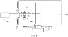
- a direct current contactor has become an important power distribution control component in a direct current charging circuit of the electric vehicle.
- a current direct current fast charging circuit an electric vehicle and a direct current fast charging apparatus are used as an example.
- a PDU 500 and a high-voltage battery pack 200 connected to the PDU 500 are disposed in the electric vehicle.
- the charging apparatus of the electric vehicle has two wiring terminals: PIN1 and PIN2.
- PIN1 is a positive terminal
- PIN2 is a negative terminal.
- the terminal PIN1 is connected to the PDU 500 by using one direct current contactor 400, the PDU 500 is connected to a positive electrode of the high-voltage battery pack 200, and the terminal PIN2 is connected to a negative electrode of the high-voltage battery pack 200 by using one direct current contactor 400.
- a connection between the direct current fast charging apparatus 300 and the high-voltage battery pack 200 is controlled by controlling the two direct current contactors to be connected or disconnected.
- one direct current contactor needs to be connected to each of the terminal PIN1 and the terminal PIN2. Consequently, the entire charging apparatus has a relatively large volume, occupies relatively large space, and has relatively high costs.
- the contactor includes two cavities, each cavity has one contactor, and each contactor includes one moving contact, one fixed contact, and one electromagnetic drive mechanism.
- One group of control lines is used to simultaneously control the two electromagnetic drive mechanisms to drive the moving contact to be connected to or disconnected from the fixed contact.
- the direct current contactor may be used for an electrical connection such as a connection between an electric vehicle and a direct current fast charging apparatus or a connection between another electric cabinet and an electrical device.
- a single drive manner is used to form two arc-extinguishing chambers in one arc-extinguishing cavity to accommodate two groups of contact components, so as to implement a dual connection between the contactor and both a positive line and a negative line, so that a structure of the direct current contactor is simplified.
- there is no need to dispose one contactor on each of the positive line and the negative line so that a volume of the charging apparatus is significantly reduced, and costs are reduced.
- the following specifically describes the direct current contactor by using an example in which the direct current contactor is used for the connection between the electric vehicle and the direct current fast charging apparatus.
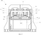
- this application provides a direct current contactor 100, including a case 10 and two groups of contact components 11 disposed in the case 10.
- Each group of contact component 11 includes two moving contacts 111 connected to each other and two fixed contacts 112 opposite to the two moving contacts 111.
- the fixed contacts 112 extend outside the case 10, so that the fixed contacts 112 are connected to a positive line or a negative line.
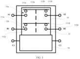
- the second group of contact component 11b includes a third moving contact 111c, a fourth moving contact 111d connected to the third moving contact 111c, and a third fixed contact 112c and a fourth fixed contact 112d that are respectively opposite to the third moving contact 111c and the fourth moving contact 111d.
- the first group of contact component 11a and the second group of contact component 11b are parallel, the first moving contact 111a and the third moving contact 111c are adjacent, and the second moving contact 111b and the fourth moving contact 111d are adjacent.
- connecting busbars may be disposed on the case 10, and are respectively a first connecting busbar A1, a second connecting busbar A2, a third connecting busbar B1, and a fourth connecting busbar B2.
- the first connecting busbar A1 and the second connecting busbar A2 are respectively connected to the first fixed contact 112a and the second fixed contact 112b.
- the third connecting busbar B1 and the fourth connecting busbar B2 are respectively connected to the third fixed contact 112c and the fourth fixed contact 112d.
- a fifth connecting busbar C1 and a sixth connecting busbar C2 may be further disposed on the case 10, to electrically connect a drive system 50.
- the first connecting busbar A1 is connected to the second connecting busbar A2.
- a current sequentially passes through the first fixed contact 112a, the first moving contact 111a, the second moving contact 111b, the second fixed contact 112b, and the second connecting busbar A2, and then flows into the positive electrode of the high-voltage battery pack.
- the moving contacts and the fixed contacts of the first group of contact component 11a may be controlled to be connected to or disconnected from each other, to control the positive line to be connected/disconnected, and the moving contacts and the fixed contacts of the second group of contact component 11b may be controlled to be connected to or disconnected from each other, to control the negative line to be connected/disconnected.
- connection/disconnection requirements of the positive line and the negative line can be met by using one direct current contactor 100, and there is no need to mount one direct current contactor on each of the positive line and the negative of the charging apparatus.
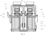
- the first baffle 13 plays a role of blocking the first arc-extinguishing chamber 121 and the second arc-extinguishing chamber 122, and may prevent arcs in the two arc-extinguishing chambers from being in contact with each other, reduce a risk of a short circuit, and improve break performance of the direct current contactor 100.
- one arc-extinguishing cavity 12 is divided into two arc-extinguishing chambers, to respectively dispose the two groups of contact components 11.
- this manner can simplify a structural design of the contactor, reduce a size of the contactor, and reduce a volume of the charging apparatus.
- the single drive system 50 is used to drive the moving contacts 111 of the two groups of contact components 11 to move, so that the positive line and the negative line are connected/disconnected.
- a single drive manner can simplify a structural design of the contactor, reduce a size of the contactor, and reduce a volume of the charging apparatus.
- the two groups of contact components 11 are simultaneously driven by using one drive system 50, so that connection/disconnection synchronization between the two groups of contact components 11 can be improved, to improve connection/disconnection synchronization between the positive line and the negative line in the charging apparatus, and improve reliability of the charging apparatus.
- a first magnet 14 and a second magnet 15 are respectively disposed on two sides that are outside the first arc-extinguishing chamber 121 and that are adjacent to the two moving contacts 111.
- the first magnet 14 is adjacent to the first moving contact 111a
- the second magnet 15 is adjacent to the second moving contact 111b
- the first magnet 14 and the second magnet 15 attract each other to form a first magnetic field
- the first magnet 14 and the second magnet 15 are opposite to gaps between the moving contacts 111 and the fixed contacts 112.
- the first magnet 14 and the second magnet 15 are configured to extinguish arcs generated between the moving contacts 111 and the fixed contacts 112 in the first group of contact component 11a.
- a magnetic field direction of the first magnetic field is perpendicular to directions of currents flowing through the fixed contacts 112 and the moving contacts 111.
- a direction of a current flowing through the first fixed contact 112a and the first moving contact 111a is a direction pointing from the first fixed contact 112a to the first moving contact 111a.
- the direction of the current is outward (towards the outside of paper).
- a current flowing through the second fixed contact 112b and the second moving contact 111b is inward (towards the inside of paper).
- An end that is of the first magnet 14 and that is close to the first moving contact 111a is the S pole
- an end that is of the second magnet 15 and that is close to the second moving contact 111b is the N pole.
- the direction of the first magnetic field is an upward direction shown in FIG. 8 , and points from the second magnet 15 to the first magnet 14. According to the left-hand rule, it may be learned that an arc between the first moving contact 111a and the first fixed contact 112a is blown to the left (namely, a direction of a in the figure) shown in FIG.
- a third magnet 16 and a fourth magnet 17 are respectively disposed on two sides that are outside the second arc-extinguishing chamber 122 and that are adjacent to the two moving contacts 111.
- the third magnet 16 is adjacent to the third moving contact 111c
- the fourth magnet 17 is adjacent to the fourth moving contact 111d
- the third magnet 16 and the fourth magnet 17 attract each other to form a second magnetic field
- the third magnet 16 and the fourth magnet 17 are opposite to gaps between the moving contacts 111 and the fixed contacts 112.
- the third magnet 16 and the fourth magnet 17 are configured to extinguish arcs generated between the moving contacts 111 and the fixed contacts 112 in the second group of contact component 11b.
- a magnetic field direction of the second magnetic field is perpendicular to directions of currents flowing through the fixed contacts 112 and the moving contacts 111. As shown in FIG. 8 , a current flowing through the third fixed contact 112c and the third moving contact 111c is inward, and a current flowing through the fourth fixed contact 112d and the fourth moving contact 111d is outward. An end that is of the third magnet 16 and that is close to the third moving contact 111c is the N pole, and an end that is of the fourth magnet 17 and that is close to the fourth moving contact 111d is the S pole, in other words, the direction of the second magnetic field is a downward direction shown in FIG. 8 , and points from the third magnet 16 to the fourth magnet 17.
- an arc between the third moving contact 111c and the third fixed contact 112c is blown to the left (namely, a direction of c in the figure) shown in FIG. 8 under the magnetic field force
- an arc between the fourth moving contact 111d and the fourth fixed contact 112d is blown to the right (namely, a direction of d in the figure) under the magnetic field force, so that the arc is blown into the second arc-extinguishing chamber and extinguished.
- the first connecting busbar A1 may be connected to the terminal PIN2.
- a direction of a current flowing through the first fixed contact 112a and the first moving contact 111a is a direction pointing from the first moving contact 111a to the first fixed contact 112a.
- the direction of the current is inward.
- a direction of a current flowing through the second fixed contact 112b and the second moving contact 111b is outward.
- the direction of the first magnetic field is still upward, and points from the second magnet 15 to the first magnet 14.
- an arc between the first moving contact 111a and the first fixed contact 112a is blown to the right (namely, a direction of a in the figure) under the magnetic field force, and an arc between the second moving contact 111b and the second fixed contact 112b is blown to the left (namely, a direction of b in the figure), so that the arc is blown into the first-extinguishing chamber 121 and extinguished.
- a current flowing through the third fixed contact 112c and the third moving contact 111c is outward
- a current flowing through the fourth fixed contact 112d and the fourth moving contact 111d is inward
- the direction of the second magnetic field points from the third magnet 16 to the fourth magnet 17.
- the magnetic field direction of the first magnetic field is opposite to the magnetic field direction of the second magnetic field.
- arc-blow directions between the moving contacts 111 and the fixed contacts 112 in the first arc-extinguishing chamber 121 may be the same as arc-blow directions between the moving contacts 111 and the fixed contacts 112 that are in the second arc-extinguishing chamber 122 and that are adjacent to the moving contacts 111 and the fixed contacts 112 in the first arc-extinguishing chamber 121.
- an arc-blow direction between the first moving contact 111a and the first fixed contact 112a is the same as an arc-blow direction between the third moving contact 111c and the third fixed contact 112c
- an arc-blow direction between the second moving contact 111b and the fixed contact 112b is the same as an arc-blow direction between the fourth moving contact 111d and the fourth fixed contact 112d. Therefore, the two arcs generated by the first group of contact component 11a and the second group of contact component 11b do not move in a direction opposite to each other during forward break and reverse break. This reduces a risk of arc collision, arc aggregation, and a short circuit, and effectively improves break performance.
- the current flowing through the first fixed contact 112a and the first moving contact 111a is outward
- the current flowing through the second fixed contact 112b and the second moving contact 111b is inward
- the direction of the first magnetic field is upward and points from the second magnet 15 to the first magnet 14
- the arc-blow direction between the first moving contact 111a and the first fixed contact 112a is leftward
- the arc-blow direction between the second moving contact 111b and the second fixed contact 112b is rightward.
- the current flowing through the third fixed contact 112c and the third moving contact 111c is inward
- the current flowing through the fourth fixed contact 112d and the fourth moving contact 111d is outward
- the direction of the second magnetic field is opposite to the direction of the first magnetic field
- the direction of the second magnetic field is downward and points from the third magnet 16 to the fourth magnet 17
- the arc-blow direction between the third moving contact 111c and the third fixed contact 112c is leftward
- the arc-blow direction between the fourth moving contact 111d and the fourth fixed contact 112d is rightward.
- the arc-blow direction between the first moving contact 111a and the first fixed contact 112a is the same as the arc-blow direction between the third moving contact 111c and the third fixed contact 112c that are adjacent to the first moving contact 111a and the first fixed contact 112a
- the arc-blow direction between the second moving contact 111b and the second fixed contact 112b is the same as the arc-blow direction between the fourth moving contact 111d and the fourth fixed contact 112d that are adjacent to the second moving contact 111b and the second fixed contact 112b.
- the current flowing through the first fixed contact 112a and the first moving contact 111a is inward
- the current flowing through the second fixed contact 112b and the second moving contact 111b is outward
- the direction of the first magnetic field is upward and points from the second magnet 15 to the first magnet 14
- the arc-blow direction between the first moving contact 111a and the first fixed contact 112a is rightward
- the arc-blow direction between the second moving contact 111b and the second fixed contact 112b is leftward.
- the current flowing through the third fixed contact 112c and the third moving contact 111c is outward, the current flowing through the fourth fixed contact 112d and the fourth moving contact 111d is inward, the direction of the second magnetic field is downward and points from the third magnet 16 to the fourth magnet 17, the arc-blow direction between the third moving contact 111c and the third fixed contact 112c is rightward, and the arc-blow direction between the fourth moving contact 111d and the fourth fixed contact 112d is leftward.
- the arc-blow direction between the first moving contact 111a and the first fixed contact 112a is the same as the arc-blow direction between the third moving contact 111c and the third fixed contact 112c that are adjacent to the first moving contact 111a and the first fixed contact 112a
- the arc-blow direction between the second moving contact 111b and the second fixed contact 112b is the same as the arc-blow direction between the fourth moving contact 111d and the fourth fixed contact 112d that are adjacent to the second moving contact 111b and the second fixed contact 112b.
- a material used to form the case 10 may be a magnetic conductive material such as a ceramic, and may play a role of shielding an external magnetic field.
- the first baffle 13 in the case 10 may be formed through protrusion on an inner top wall of the case 10, the first baffle 13 and the case 10 may be integrally formed, and the first baffle 13 may prevent arcs blowing into the first arc-extinguishing chamber 121 and the second arc-extinguishing chamber 122 from being in contact with each other, to further improve break performance of the direct current contactor 100.
- the direct current contactor 100 further includes a mounting bracket 18.
- the mounting bracket 18 includes a first bracket 181 and a second bracket 182 that are opposite to each other.
- the first bracket 181 and the second bracket 182 are disposed around a periphery of the case 10.
- the first magnet 14 and the second magnet 15 are disposed on an inner side wall of the first bracket 181.
- the third magnet 16 and the fourth magnet 17 are disposed on an inner side wall of the second bracket 182.
- the first bracket 181 is located on a periphery of the first arc-extinguishing chamber 121
- the second bracket 182 is located on a periphery of the second arc-extinguishing chamber 122.
- the first magnet 14 and the second magnet 15 are disposed outside the first extinguishing chamber 121 by using the first bracket 181, and the third magnet 16 and the fourth magnet 17 are disposed outside the second arc-extinguishing chamber 122 by using the second bracket 182.
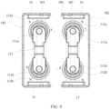
- the first bracket 181 and the second bracket 182 may be U-shaped brackets. Referring to FIG. 11 , a side wall of the U-shaped bracket has a first clamping member 183, an end of an opening of the U-shaped bracket has a second clamping member 184 protruding towards the inside of the opening, and at least one of the first magnet 14, the second magnet 15, the third magnet 16, and the fourth magnet 17 is disposed on the U-shaped bracket by using the first clamping member 183 and the second clamping member 184. In other words, the first magnet 14, the second magnet 15, the third magnet 16, and the fourth magnet 17 are disposed on the first bracket 181 and the second bracket 182 through clamping. This can facilitate assembly, disassembly, and replacement.
- the first clamping member 183 may be a clamping jaw, a clamping slot, or another clamping member that is disposed on an outer wall of a side of the U-shaped bracket, and the second clamping member 184 may also be a clamping jaw, a clamping slot, or another clamping member that is formed after the end of the opening protrudes towards the inside.
- the first bracket 181 and the second bracket 182 may be magnetic conductive plates with magnetic conductive performance.
- the first bracket 181 and the second bracket 182 are disposed around the periphery of the case 10.
- the first bracket 181 may be disposed around on the periphery of the first arc-extinguishing chamber 121
- the second bracket 182 may be disposed on the periphery of the second arc-extinguishing chamber 122, so that the first bracket 181 and the second bracket 182 are magnetic conductive plates such as metal brackets, and can play a role of shielding the external magnetic field, to improve arc-extinguishing performance of the first arc-extinguishing chamber 121 and the second arc-extinguishing chamber 122, and improve break performance of the direct current contactor 100.
- the first magnet 14, the second magnet 15, the third magnet 16, and the fourth magnet 17 may be permanent magnets, have relatively strong magnetism, and are not easy to be demagnetized, so that the magnetic field force of the first magnetic field and the second magnetic field can be ensured, and arc-blow and arc-extinguishing effects are ensured.
- the magnet has a relatively long service life, to help improve reliability of the direct current contactor 100.
- the direct current contactor 100 further includes a housing 20, and the mounting bracket 18 is located in the housing 20.
- a side or a corner of the at least one of the first magnet 14, the second magnet 15, the third magnet 16, and the fourth magnet 17 has a hole 19.
- an inner side wall of the housing 20 has a first protrusion 21 corresponding to the hole 19.
- the housing 20 is buckled on the case 10, and the first clamping member 183 is adjacent to the moving contact 111.
- the first clamping member 183 is located on an outer side wall of an end that is of the U-shaped bracket and that is close to the moving contact 111.
- a side that is of the magnet and that is close to the fixed contact 112 is not limited. Consequently, there is a slip risk.
- an inner wall of an end that is of the housing 20 and that is adjacent to the fixed contact 112 has a second protrusion 22.
- a side wall of the at least one of the first magnet 14, the second magnet 15, the third magnet 16, and the fourth magnet 17 abuts against a side wall of the second protrusion 22. In this way, a position of the magnet is further limited by using the second protrusion 22.
- the first clamping member 183, the second clamping member 184, and the second protrusion 22 jointly limit the magnet, to prevent the magnet from falling off the U-shaped bracket, and improve disposition stability of the magnet.
- the direct current contactor 100 further includes a base plate 30.
- the case 10 covers the base plate 30.
- the case 10 and the base plate 30 surround the arc-extinguishing cavity 12.
- the base plate 30 and the case 10 may surround a sealed arc-extinguishing cavity 12.
- the base plate 30 may also be a magnetic conductive plate with magnetic conductive performance such as a ceramic, so that the external magnetic field can be shielded.
- the case 10 and the base plate 30 may be connected through welding, bonding, clamping and fastening, and the like.
- the case 10 and the base plate 30 may be directly connected, or the case 10 and the base plate 30 may be indirectly connected.
- the case 10 and the base plate 30 are connected by using a connecting piece 40.
- the case 10 and the base plate 30 may be connected through welding by using a metal connecting piece 40.
- a side wall that is of the first baffle 13 and that faces the first arc-extinguishing chamber 121 has a third protrusion 131, and one side wall of the first baffle 13 is used as a side wall of the first arc-extinguishing chamber 121.
- the arc between the first moving contact 111a and the first fixed contact 112a or between the second moving contact 111b and the second fixed contact 112b is blown to the side wall.
- the third protrusion 131 is disposed on the side wall, a length of the side wall is increased, and a creepage distance between the first moving contact 111a and the first fixed contact 112a, and the second moving contact 111b and the second fixed contact 112b is increased. This helps extinguish the arc in a timely manner, saves space required for arc extinguishing, further improves break performance of the direct current contactor 100, and helps reduce a volume of the direct current contactor 100.
- a side wall that is of the first baffle 13 and that faces the second arc-extinguishing chamber 122 has a fourth protrusion 132, and the other side wall of the first baffle 13 is used as a side wall of the second arc-extinguishing chamber 122.
- the arc between the third moving contact 111c and the third fixed contact 112c or between the fourth moving contact 111d and the fourth fixed contact 112d is blown to the side wall.
- the fourth protrusion 132 is disposed on the side wall, similarly, a length of the side wall is increased, and a creepage distance between the third moving contact 111c and the third fixed contact 112c, and the fourth moving contact 111d and the fourth fixed contact 112d is increased. This helps extinguish the arc in a timely manner, saves space required for arc extinguishing, and further improves break performance of the direct current contactor 100.
- the two third protrusions 131 divide the first arc-extinguishing chamber 121 into three layers shown in FIG. 5 .
- the first moving contact 111a and the first fixed contact 112a, and the second moving contact 111b and the second fixed contact 112b are respectively located at two layers at ends.
- the two fourth protrusions 132 divide the second arc-extinguishing chamber 122 into three layers.
- the third moving contact 111c and the third fixed contact 112c, and the fourth moving contact 111d and the fourth fixed contact 112d are respectively located at two layers at ends.
- a side wall that is of the first arc-extinguishing chamber 121 and that is opposite to the first baffle 13 may have a fifth protrusion 1211.
- the arc between the first moving contact 111a and the first fixed contact 112a or between the second moving contact 111b and the second fixed contact 112b in the first arc-extinguishing chamber 121 may be blown to the side wall.
- the fifth protrusion 1211 is disposed on the side wall, a length of the side wall may be increased, and the creepage distance between the first moving contact 111a and the first fixed contact 112a, and the second moving contact 111b and the second fixed contact 112b may be increased. This helps extinguish the arc in a timely manner, saves space required for arc extinguishing, and further improves break performance of the direct current contactor 100.
- a side wall that is of the second arc-extinguishing chamber 122 and that is opposite to the first baffle 13 may have a sixth protrusion 1221.
- the arc between the third moving contact 111c and the third fixed contact 112c or between the fourth moving contact 111d and the fourth fixed contact 112d is blown to the side wall.
- the sixth protrusion 1221 exists on the side wall, similarly, a length of the side wall is increased, and the creepage distance between the third moving contact 111c and the third fixed contact 112c, and the fourth moving contact 111d and the fourth fixed contact 112d is increased. This helps extinguish the arc in a timely manner, saves space required for arc extinguishing, and further improves break performance of the direct current contactor 100.
- the drive system 50 includes a drive component 51 and a moving component 52.
- the moving component 52 includes a support rod 521 and a moving plate 522 connected to the support rod 521.
- the moving plate 522 is located in the arc-extinguishing cavity 12, and the moving contacts 111 of the two groups of contact components 11 are disposed on the moving plate 522.
- the first moving contact 111a, the second moving contact 111b, the third moving contact 111c, and the fourth moving contact 111d are disposed on the moving plate 522.
- the driving component 51 is configured to drive the moving component 52 to move to drive the moving contacts 111 to move.
- the driving component 51 may drive the support rod 521 in the moving component 52 to move up and down, and the support rod 521 drives the moving plate 522 to move, to drive the moving contacts 111 on the moving plate 522 to move in the direction close to or away from the fixed contacts 112, so that the moving contacts 111 are connected to or disconnected from the fixed contacts 112.
- the moving plate 522 is a plate-like structure with an area. Compared with an existing manner in which the moving contacts are disposed on a connecting rod, in this manner, the moving plate 522 may provide higher strength and have higher mechanical strength. This helps improve reliability of the direct current contactor 100.
- the moving plate 522 and the support rod 521 may be integrally formed, or the support rod 521 and the moving plate 522 may be separately disposed. Specifically, the support rod 521 and the moving plate 522 may be fastened and connected through thread-connection, welding, bonding, and the like.
- the moving contacts 111 when the moving contacts 111 are disconnected from the fixed contacts 112, there is a gap between the first baffle 13 and the moving plate 522.
- the gap provides space for the moving plate 522 to move, so as to ensure that the moving plate 522 can move to drive the moving contacts 111 to move.
- the moving plate 522 has a second baffle 5221, and the second baffle 5221 is located on an outer side of the gap, to ensure that the second baffle 5221 does not affect movement of the moving plate 522.
- the second baffle 5221 extends towards the first baffle 13, and the second baffle 5221 at least partially overlaps the first baffle 13.
- the second baffle 5221 may be a baffle plate, or the second baffle 5221 may be a mechanical part with a baffle plate.
- the moving plate 522 may have one second baffle 5221, or may have a plurality of second baffles 5221.
- a groove 5222 is disposed on the moving plate 522, a side wall of the groove 5222 forms the second baffle 5221, and the first baffle 13 may extend into the groove 5222.
- the first baffle 13 extends into the groove 5222.
- the groove 5222 has two side walls and one bottom wall connected to the two side walls. The two side walls of the groove 5222 are used as two second baffles 5221, and the two second baffles 5221 and the first baffle 13 jointly isolate and separate the first arc-extinguishing chamber 121 and the second arc-extinguishing chamber 122.
- the groove 5222 and the moving plate 522 may be integrally formed, or the groove 5222 may be separately formed and then disposed on the moving plate 522.
- the groove 5222 and the moving plate 522 may be disposed through clamping, bonding, welding, thread-fastening, and the like.
- the second baffle 5221 may be disposed only at each of positions that are on the moving plate 522 and that are opposite to the two moving contacts 111, and no second baffle 5221 may be disposed at a position opposite to a position at which the moving contacts 111 are connected. In this way, a structure of the moving component 52 can be simplified, and costs can also be reduced.
- the drive system 50 further includes a drive chamber 53, and the drive component 51 is located in the drive chamber 53.
- one end of the support rod 521 is located in the drive chamber 53, and the other end of the support rod 521 extends into the arc-extinguishing cavity 12.
- the drive chamber 53 may be connected to the case 10.
- the drive chamber 53 and the case 10 may share the base plate 30, in other words, the base plate 30 is used as a side wall of the drive chamber 53.
- the base plate 30 may have a through hole, and the other end of the support rod 521 may extend into the arc-extinguishing cavity 12 through the through hole.
- the reset spring 513 is sleeved on a periphery of the support rod 521, and one end of the reset spring 513 abuts against the moving iron core 512, and the other end of the reset spring 513 abuts against the fixed iron core 511.
- the drive component 51 may further include an electromagnetic coil 514 that surrounds the fixed iron core 511 and the moving iron core 512. When the electromagnetic coil 514 is powered on, the fixed iron core 511 and the moving iron core 512 attract each other.
- the electromagnetic coil 514 When the direct current contactor 100 is used, the electromagnetic coil 514 is powered on, the fixed iron core 511 and the moving iron core 512 attract each other, and the fixed iron core 511 is fastened in the drive chamber 53.
- the moving iron core 512 moves towards the fixed iron core 511 against elastic force of the reset spring 513, and drives the support rod 521 to move.
- the support rod 521 drives the moving plate 522 to move, to drive the moving contacts 111 on the moving plate 522 to move in the direction close to the fixed contacts 112, so as to enable the moving contacts 111 to be in electrical contact with the fixed contacts 112, so that the moving contacts 111 are connected to the fixed contacts 112.
- the contact component 11 further includes a moving contact bridge 113.
- the two moving contacts 111 are connected to each other by using the moving contact bridge 113.
- the two moving contacts 111 are located on two sides of the moving contact bridge 113.
- the contact component 11 further includes an elastic component 114.
- the elastic component 114 is located between the moving contact bridge 113 and the moving plate 522.
- the elastic component 114 may be a spring.
- the elastic component 114 located between the moving plate 522 and the moving contact bridge 113 is compressed, and the compressed elastic component 114 pushes the moving contacts 111, so that the moving contacts 111 are pressed against the fixed contacts 112. This ensures reliable contact between the moving contacts 111 and the fixed contacts 112, and improves stability of a connection between the moving contacts 111 and the fixed contacts 112.
- the moving contact 111 and the elastic component 114 are connected through sleeving by using a shaft hole. Specifically, there is a connecting rod between the moving contact 111 and the moving component 52, one end of the connecting rod passes through the moving contact 111 and is fastened to the moving contact 111, and the other end of the connecting rod is fastened and connected to the moving component 52.
- the elastic component 114 is sleeved on the connecting rod. In the manner in which the moving contact 111 and the elastic component 114 are connected through sleeving by using a shaft hole, a hole need to be provided on the moving contact 111. Consequently, a conductive area of the moving contact 111 is reduced, and a conductive capability is reduced.
- the contact component 11 may further include a U-shaped fixed bracket 115, the moving contact bridge 113 and the elastic component 114 are located in the fixed bracket 115, the elastic component 114 is located between the moving contact bridge 113 and the moving plate 522, and an opening end of the fixed bracket 115 is disposed on the moving plate 522.
- the moving contact bridge 113 and the elastic component 114 are disposed on the moving plate 522 by using the fixed bracket 115, and no shaft hole needs to be provided on the moving contact 111 and the moving contact bridge 113. This avoids affecting a conductive area of the contact component 11, ensures conductive performance of the contact component 11, and helps improve a capability of the contact component 11 to carry a current.
- a seventh protrusion (not shown) may be provided at each of positions that are on the moving plate 522 and the moving contact bridge 113 and that correspond to the elastic component 114. Two ends of the elastic component 114 are respectively sleeved on peripheries of the seventh protrusions.
- the seventh protrusion may play a role of limiting and guiding the elastic component 114, so that the elastic component 114 is prevented from falling off between the moving contact bridge 113 and the moving plate 522, and the elastic component 114 can also be prevented from being distorted and then being in capable of being compressed.
- the fixed bracket 115 may be disposed on the moving plate 522 through bonding, welding, clamping, thread-connection, and the like.
- the moving plate 522 may have a boss 5223 protruding from a plane on which the moving plate 522 is located.
- the boss 5223 is configured to dispose the contact component 11, and two opposite side walls of the boss 5223 each may have a protruding third clamping member 5224.
- the opening end of the fixed bracket 115 may have a clamping slot (not shown) that can match the third clamping member 5224, and the opening end of the fixed bracket 115 may be clamped and fastened to the moving plate 522 through matching between the clamping slot and the third clamping member 5224, to fasten the moving contact 111 and the elastic component 114 to the moving plate 522 by using the fixed bracket 115.
Landscapes
- Physics & Mathematics (AREA)
- Electromagnetism (AREA)
- Engineering & Computer Science (AREA)
- Mechanical Engineering (AREA)
- Power Engineering (AREA)
- Transportation (AREA)
- Arc-Extinguishing Devices That Are Switches (AREA)
Claims (17)
- Gleichstromschütz (100, 400), das ein Gehäuse (10) und zwei Gruppen von Kontaktkomponenten (11, 11a, 11b), die in dem Gehäuse (10) angeordnet sind, umfasst, wobei jede Gruppe von Kontaktkomponenten (11, 11a, 11b) zwei bewegliche Kontakte (111), die miteinander verbunden sind, und zwei feste Kontakte (112), gegenüberliegend den beweglichen Kontakten (111), umfasst und sich die festen Kontakte (112) außerhalb des Gehäuses (10) erstrecken;das Gehäuse (10) einen Lichtbogenlöschhohlraum (12) aufweist,eine erste Trennwand (13) in dem Lichtbogenlöschhohlraum (12) angeordnet ist und die erste Trennwand (13) den Lichtbogenlöschhohlraum (12) in eine erste Lichtbogenlöschkammer (121) und eine zweite Lichtbogenlöschkammer (122) unterteilt unddie zwei Gruppen von Kontaktkomponenten (11, 11a, 11b) jeweils in der ersten Lichtbogenlöschkammer (121) und der zweiten Lichtbogenlöschkammer (122) angeordnet sind; unddas Gleichstromschütz (100, 400) ferner ein Antriebssystem (50) umfasst,wobei das Antriebssystem (50) mit den beweglichen Kontakten (111) der zwei Gruppen von Kontaktkomponenten (11, 11a, 11b) verbunden ist unddas Antriebssystem (50) konfiguriert ist, um die beweglichen Kontakte (111) anzutreiben, um sich in eine Richtung nahe an die festen Kontakten (112) oder von diesen weg zu bewegen, sodass die beweglichen Kontakte (111) von den festen Kontakten (112) gelöst oder mit diesen verbunden werden; undwobei das Antriebssystem (50) eine Antriebskomponente (51) und eine bewegliche Komponente (52) umfasst, die bewegliche Komponente (52) eine Stützstange (521) und eine bewegliche Platte (522), die mit der Stützstange (521) verbunden ist,umfasst, die bewegliche Platte (522) in dem Lichtbogenlöschhohlraum (12) gelegen ist und die beweglichen Kontakte (111) der zwei Gruppen von Kontaktkomponenten (11, 11a, 11b) an der beweglichen Platte (522) angeordnet sind; unddie Antriebskomponente (51) konfiguriert ist, um die bewegliche Komponente (52) anzutreiben, sich zu bewegen, um die beweglichen Kontakte (111) anzutreiben, sich zu bewegen, und, wenn die beweglichen Kontakte (111) von den festen Kontakten (112) gelöst werden, eine Lücke zwischen der ersten Trennwand (13) und der beweglichen Platte (522) vorhanden ist; unddadurch gekennzeichnet, dasseine Nut (5222) an der beweglichen Platte (522) angeordnet ist, wobei die zwei Seitenwände der Nut (5222) zwei zweite Trennwände (5221) ausbilden, die sich zu der ersten Trennwand (13) hin erstrecken, sodass die zweiten Trennwände (5221) die erste Trennwand (13) mindestens teilweise überlappen und sich die erste Trennwand (13) in die Nut (5222) erstreckt, um die erste Lichtbogenlöschkammer (121) und die zweite Lichtbogenlöschkammer (122) gemeinsam zu isolieren und abzugrenzen.
- Gleichstromschütz (100, 400) nach Anspruch 1, wobei ein erster Magnet (14) und ein zweiter Magnet (15) jeweils an zwei Seiten angeordnet sind, die sich außerhalb der ersten Lichtbogenlöschkammer (121) befinden und die sich angrenzend an die zwei beweglichen Kontakte (111) befinden, wobei der erste Magnet (14) und der zweite Magnet (15) sich gegenseitig anziehen, um ein erstes Magnetfeld auszubilden, und sich der erste Magnet (14) und der zweite Magnet (15) gegenüberliegend zu Lücken zwischen den beweglichen Kontakten (111) und den festen Kontakten (112) befinden; ein dritter Magnet (16) und ein vierter Magnet (17) jeweils an zwei Seiten angeordnet sind, die sich außerhalb der zweiten Lichtbogenlöschkammer (122) befinden und die sich angrenzend an die zwei beweglichen Kontakte (111) befinden, wobei der dritte Magnet (16) und der vierte Magnet (17) sich gegenseitig anziehen, um ein zweites Magnetfeld auszubilden, und sich der dritte Magnet (16) und der vierte Magnet (17) gegenüberliegend zu Lücken zwischen den beweglichen Kontakten (111) und den festen Kontakten (112) befinden; und
Magnetfeldrichtungen des ersten Magnetfelds und des zweiten Magnetfelds senkrecht zu Richtungen von Strömen, die über die festen Kontakte (112) und die beweglichen Kontakte (111) fließen, sind und die Magnetfeldrichtung des ersten Magnetfelds gegenüberliegend zu der Magnetfeldrichtung des zweiten Magnetfelds ist. - Gleichstromschütz (100, 400) nach Anspruch 2, das ferner eine Montagehalterung (18) umfasst, wobei die Montagehalterung (18) eine erste Halterung (181) und eine zweite Halterung (182) umfasst, die sich einander gegenüberliegend befinden, die erste Halterung (181) und die zweite Halterung (182) um einen Umfang des Gehäuses (10) herum angeordnet sind, der erste Magnet (14) und der zweite Magnet (15) an einer Innenseitenwand der ersten Halterung (181) angeordnet sind und der dritte Magnet (16) und der vierte Magnet (17) an einer Innenseitenwand der zweiten Halterung (182) angeordnet sind.
- Gleichstromschütz (100, 400) nach Anspruch 3, wobei die erste Halterung (181) und die zweite Halterung (182) U-förmige Halterungen sind, eine Seitenwand der U-förmigen Halterung ein erstes Klemmelement (183) aufweist, ein Ende einer Öffnung der U-förmigen Halterung ein zweites Klemmelement (184), das zu der Innenseite der Öffnung hin vorspringt, aufweist und mindestens einer des ersten Magneten (14), des zweiten Magneten (15), des dritten Magneten (16) oder des vierten Magneten (17) durch Verwenden des ersten Klemmelements (183) und des zweiten Klemmelements (184) an der U-förmigen Halterung angeordnet ist.
- Gleichstromschütz (100, 400) nach Anspruch 4, das ferner eine Einhausung (20) umfasst, wobei die Montagehalterung (18) in der Einhausung (20) gelegen ist, eine Seite oder eine Ecke des mindestens einen des ersten Magneten (14), des zweiten Magneten (15), des dritten Magneten (16) und des vierten Magneten (17) ein Loch (19) aufweist und eine Innenseitenwand der Einhausung (20) einen ersten Vorsprung (21), der dem Loch (19) entspricht, aufweist.
- Gleichstromschütz (100, 400) nach Anspruch 5, wobei sich das erste Klemmelement (183) angrenzend an den beweglichen Kontakt (11, 111, 111a-d) befindet, eine Innenwand eines Endes, die zu dem Gehäuse (20) gehört und die sich angrenzend an den festen Kontakt (112, 112a-d) befindet, einen zweiten Vorsprung (22) aufweist und eine Seitenwand des mindestens einen des ersten Magneten (14), des zweiten Magneten (15), des dritten Magneten (16) und des vierten Magneten an einer Seitenwand des zweiten Vorsprungs (22) anliegt.
- Gleichstromschütz (100, 400) nach einem der Ansprüche 3 bis 6, wobei die erste Halterung (181) und die zweite Halterung (182) magnetische leitfähige Platten mit magnetischer leitfähiger Leistung sind.
- Gleichstromschütz (100, 400) nach einem der Ansprüche 2 bis 7, wobei der erste Magnet (14), der zweite Magnet (15), der dritte Magnet (16) und der vierte Magnet (17) Permanentmagnete sind.
- Gleichstromschütz (100, 400) nach einem der Ansprüche 1 bis 8, das ferner eine Grundplatte (30) umfasst, wobei das Gehäuse (10) an der Grundplatte (30) angeordnet ist und das Gehäuse (10) und die Grundplatte (30) den Lichtbogenlöschhohlraum (12) umgeben.
- Gleichstromschütz (100, 400) nach Anspruch 9, wobei das Gehäuse (10) und die Grundplatte (30) durch Verwenden eines Verbindungsstücks (40) verbunden sind.
- Gleichstromschütz (100, 400) nach einem der Ansprüche 1 bis 10, wobei eine Seitenwand, die zu der ersten Trennwand (13) gehört und die der ersten Lichtbogenlöschkammer (121) zugewandt ist, einen dritten Vorsprung (131) aufweist und eine Seitenwand, die zu der ersten Trennwand (13) gehört und die der zweiten Lichtbogenlöschkammer (122) zugewandt ist, einen vierten Vorsprung (132) aufweist.
- Gleichstromschütz (100, 400) nach einem der Ansprüche 1 bis 11, wobei eine Seitenwand, die zu der ersten Lichtbogenlöschkammer (121) gehört und die sich gegenüberliegend zu der ersten Trennwand (13) befindet, einen fünften Vorsprung (1211) aufweist und eine Seitenwand, die zu der zweiten Lichtbogenlöschkammer (122) gehört und die sich gegenüberliegend zu der ersten Trennwand (13) befindet, einen sechsten Vorsprung (1221) aufweist.
- Gleichstromschütz (100, 400) nach Anspruch 1, wobei die zweiten Trennwände (5221) an jeder von Positionen angeordnet sind, die sich an der beweglichen Platte (522) befinden und die sich gegenüberliegend zu den zwei beweglichen Kontakten (111) befinden.
- Gleichstromschütz (100, 400) nach einem der Ansprüche 1 bis 13, wobei das Antriebssystem (50) ferner eine Antriebskammer (53) umfasst, die Antriebskomponente (51) in der Antriebskammer (53) gelegen ist, ein Ende der Stützstange (521) in der Antriebskammer (53) gelegen ist und sich das andere Ende der Stützstange (521) in den Lichtbogenlöschhohlraum (12) erstreckt.
- Gleichstromschütz (100, 400) nach einem der Ansprüche 1 bis 14, wobei die Kontaktkomponente (11, 11a, 11b) ferner eine Brücke für den beweglichen Kontakt (11, 111, 111a-d) und eine elastische Komponente (114) umfasst, die zwei beweglichen Kontakte (111) durch Verwenden der Brücke für den beweglichen Kontakt (11, 111, 111a-d) verbunden sind und die elastische Komponente (114) zwischen der Brücke für den beweglichen Kontakt (11, 111, 111a-d) und der beweglichen Platte (522) gelegen ist.
- Gleichstromschütz (100, 400) nach Anspruch 15, wobei die Kontaktkomponente (11, 11a, 11b) ferner eine U-förmige feste Halterung (115) umfasst, die Brücke für den beweglichen Kontakt (11, 111, 111a-d) und die elastische Komponente (114) in der festen Halterung (115) gelegen sind und ein Öffnungsende der festen Halterung (115) an der beweglichen Platte (522) angeordnet ist.
- Fahrzeug, das mindestens das Gleichstromschütz (100, 400) nach einem der Ansprüche 1 bis 16 umfasst.
Applications Claiming Priority (2)
| Application Number | Priority Date | Filing Date | Title |
|---|---|---|---|
| CN202010591488.5A CN111863538A (zh) | 2020-06-24 | 2020-06-24 | 一种直流接触器及车辆 |
| PCT/CN2021/093420 WO2021258895A1 (zh) | 2020-06-24 | 2021-05-12 | 一种直流接触器及车辆 |
Publications (3)
| Publication Number | Publication Date |
|---|---|
| EP4145485A1 EP4145485A1 (de) | 2023-03-08 |
| EP4145485A4 EP4145485A4 (de) | 2023-09-20 |
| EP4145485B1 true EP4145485B1 (de) | 2025-03-26 |
Family
ID=72988163
Family Applications (1)
| Application Number | Title | Priority Date | Filing Date |
|---|---|---|---|
| EP21829112.8A Active EP4145485B1 (de) | 2020-06-24 | 2021-05-12 | Gleichstromschütz und fahrzeug |
Country Status (4)
| Country | Link |
|---|---|
| US (1) | US12198884B2 (de) |
| EP (1) | EP4145485B1 (de) |
| CN (1) | CN111863538A (de) |
| WO (1) | WO2021258895A1 (de) |
Families Citing this family (12)
| Publication number | Priority date | Publication date | Assignee | Title |
|---|---|---|---|---|
| CN110783147B (zh) * | 2019-09-29 | 2021-03-23 | 华为技术有限公司 | 一种直流接触器及汽车 |
| CN111863538A (zh) * | 2020-06-24 | 2020-10-30 | 华为技术有限公司 | 一种直流接触器及车辆 |
| CN112786367B (zh) * | 2021-02-07 | 2025-07-25 | 三友联众集团股份有限公司 | 一种便装引线式电磁继电器 |
| CN115249600B (zh) * | 2021-04-27 | 2024-10-29 | 比亚迪股份有限公司 | 继电器 |
| CN115742782B (zh) * | 2021-09-03 | 2025-09-09 | 比亚迪股份有限公司 | 用于车辆的接触器、车辆充配电系统、充电桩以及车辆 |
| CN114188191B (zh) * | 2021-10-29 | 2024-11-29 | 华为数字能源技术有限公司 | 配电模块和车辆 |
| KR102678169B1 (ko) * | 2021-11-18 | 2024-06-24 | 엘에스일렉트릭(주) | 아크 경로 형성부 및 이를 포함하는 직류 릴레이 |
| KR102678161B1 (ko) * | 2021-11-18 | 2024-06-24 | 엘에스일렉트릭(주) | 아크 경로 형성부 및 이를 포함하는 직류 릴레이 |
| CN114464502B (zh) * | 2022-01-07 | 2024-05-17 | 华为数字能源技术有限公司 | 直流接触器 |
| CN114792610A (zh) * | 2022-04-02 | 2022-07-26 | 华为数字能源技术有限公司 | 供电系统及开关单元 |
| CN121122941A (zh) * | 2024-06-11 | 2025-12-12 | 华为数字能源技术有限公司 | 开关装置、并离网切换装置和供电系统 |
| CN119314819A (zh) * | 2024-12-19 | 2025-01-14 | 浙光电气(浙江)有限公司 | 一种封闭圆形陶瓷高压直流磁吹灭弧室 |
Family Cites Families (20)
| Publication number | Priority date | Publication date | Assignee | Title |
|---|---|---|---|---|
| JPH02250229A (ja) * | 1989-03-24 | 1990-10-08 | Mitsubishi Electric Corp | 電磁接触器 |
| CN2337662Y (zh) * | 1998-03-17 | 1999-09-08 | 桂林机床电器厂 | 带护罩的双极交流接触器 |
| JP2004311389A (ja) * | 2003-02-21 | 2004-11-04 | Sumitomo Electric Ind Ltd | 直流リレー |
| JP2005332588A (ja) * | 2004-05-18 | 2005-12-02 | Fuji Electric Fa Components & Systems Co Ltd | 電磁接触器 |
| US8193881B2 (en) * | 2007-09-14 | 2012-06-05 | Fujitsu Component Limited | Relay |
| US7868720B2 (en) * | 2007-11-01 | 2011-01-11 | Tyco Electronics Corporation India | Hermetically sealed relay |
| US8232499B2 (en) * | 2009-11-18 | 2012-07-31 | Tyco Electronics Corporation | Contactor assembly for switching high power to a circuit |
| US8653691B2 (en) * | 2011-01-13 | 2014-02-18 | GM Global Technology Operations LLC | Dual bipolar magnetic field for linear high-voltage contactor in automotive lithium-ion battery systems |
| JP5085754B2 (ja) * | 2011-03-14 | 2012-11-28 | オムロン株式会社 | 電磁継電器 |
| CN204155859U (zh) | 2014-09-16 | 2015-02-11 | 浙江宏舟新能源科技有限公司 | 一种并联双路高压直流接触器 |
| CN104882335B (zh) | 2015-03-31 | 2017-07-28 | 厦门宏发电力电器有限公司 | 一种磁钢错位分布的灭弧磁路及其直流继电器 |
| CN107026056B (zh) | 2017-05-09 | 2019-08-27 | 三友联众集团股份有限公司 | 一种带有辅助触点的直流接触器 |
| CN107331583A (zh) * | 2017-08-15 | 2017-11-07 | 昆山国力源通新能源科技有限公司 | 无极性高压直流接触器灭弧系统结构 |
| CN208045411U (zh) | 2018-03-26 | 2018-11-02 | 三友联众集团股份有限公司 | 一种高压直流接触器 |
| CN108922827A (zh) * | 2018-07-26 | 2018-11-30 | 哈尔滨工业大学 | 一种四断点接触器中的接触机构 |
| CN208796916U (zh) | 2018-11-14 | 2019-04-26 | 沈阳二一三控制电器制造有限公司 | 一种无极性陶瓷密封双极直流接触器 |
| US10483068B1 (en) * | 2018-12-11 | 2019-11-19 | Eaton Intelligent Power Limited | Switch disconnector systems suitable for molded case circuit breakers and related methods |
| KR102339179B1 (ko) * | 2019-07-11 | 2021-12-14 | 엘에스일렉트릭 (주) | 아크 경로 형성부 및 이를 포함하는 직류 릴레이 |
| CN210640160U (zh) * | 2019-09-24 | 2020-05-29 | 上海为鹏科技有限公司 | 一种直流接触器的灭弧结构 |
| CN111863538A (zh) * | 2020-06-24 | 2020-10-30 | 华为技术有限公司 | 一种直流接触器及车辆 |
-
2020
- 2020-06-24 CN CN202010591488.5A patent/CN111863538A/zh active Pending
-
2021
- 2021-05-12 WO PCT/CN2021/093420 patent/WO2021258895A1/zh not_active Ceased
- 2021-05-12 EP EP21829112.8A patent/EP4145485B1/de active Active
-
2022
- 2022-12-07 US US18/062,788 patent/US12198884B2/en active Active
Also Published As
| Publication number | Publication date |
|---|---|
| WO2021258895A1 (zh) | 2021-12-30 |
| CN111863538A (zh) | 2020-10-30 |
| US20230098632A1 (en) | 2023-03-30 |
| US12198884B2 (en) | 2025-01-14 |
| EP4145485A1 (de) | 2023-03-08 |
| EP4145485A4 (de) | 2023-09-20 |
Similar Documents
| Publication | Publication Date | Title |
|---|---|---|
| EP4145485B1 (de) | Gleichstromschütz und fahrzeug | |
| KR101342981B1 (ko) | 스위칭 어셈블리, 차량 추진 시스템 및 스위칭 어셈블리의 작동 방법 | |
| US9373467B2 (en) | Electromagnetic contactor | |
| JP5303022B2 (ja) | 自動車リチウムイオン電池システムにおける直線状高電圧接触器用の2重双極性磁界 | |
| EP4210084B1 (de) | Gleichstromschütz, verteilerkasten, strombatterieanordnung und fahrzeug | |
| US12057281B2 (en) | Direct current contactor and vehicle | |
| JP2022518426A (ja) | アークサプレッサを有する接触器 | |
| WO2025041552A1 (ja) | 継電器及び継電ユニット | |
| AU2022336934A1 (en) | Distributor, charging and distributing system of vehicle, vehicle, and charging pile | |
| CN114256029B (zh) | 继电器 | |
| CN219873234U (zh) | 一种灭弧装置以及接触器 | |
| US20260031284A1 (en) | Switching device | |
| WO2021214696A1 (en) | Contactor with arc suppressor | |
| JP7610762B2 (ja) | コンタクタデバイス及びエネルギー貯蔵システム | |
| CN111933488A (zh) | 动触点结构及接触器 | |
| WO2024112124A1 (ko) | 전자석 접점 장치 | |
| WO2024025383A1 (ko) | 개선된 가동대 홀더를 갖는 접점 장치 | |
| KR20240010021A (ko) | 차량용 콘택터, 차량 충전 및 전력 분배 시스템, 충전 파일, 및 차량 | |
| EP3005394B1 (de) | Anordnung für ein elektrisches schaltelelement, insbesondere schütz oder relais, und elektrisches schaltelelement mit einem steuerungsmodul zwischen jochschenkel und spule | |
| CN115742785B (zh) | 接触器、充电桩以及车辆 | |
| CN115742788B (zh) | 接触器、充电桩以及车辆 | |
| EP4629275A1 (de) | Relais | |
| EP4394837A1 (de) | Schütz, lade- und stromverteilungssystem, fahrzeug und ladesäule | |
| CN121488313A (zh) | 开关单元 | |
| JP2005019163A (ja) | リレー装置 |
Legal Events
| Date | Code | Title | Description |
|---|---|---|---|
| STAA | Information on the status of an ep patent application or granted ep patent |
Free format text: STATUS: THE INTERNATIONAL PUBLICATION HAS BEEN MADE |
|
| PUAI | Public reference made under article 153(3) epc to a published international application that has entered the european phase |
Free format text: ORIGINAL CODE: 0009012 |
|
| STAA | Information on the status of an ep patent application or granted ep patent |
Free format text: STATUS: REQUEST FOR EXAMINATION WAS MADE |
|
| 17P | Request for examination filed |
Effective date: 20221130 |
|
| AK | Designated contracting states |
Kind code of ref document: A1 Designated state(s): AL AT BE BG CH CY CZ DE DK EE ES FI FR GB GR HR HU IE IS IT LI LT LU LV MC MK MT NL NO PL PT RO RS SE SI SK SM TR |
|
| REG | Reference to a national code |
Ref legal event code: R079 Ipc: H01H0050380000 Ref country code: DE Ref legal event code: R079 Ref document number: 602021028245 Country of ref document: DE Free format text: PREVIOUS MAIN CLASS: H01H0050540000 Ipc: H01H0050380000 |
|
| A4 | Supplementary search report drawn up and despatched |
Effective date: 20230818 |
|
| RIC1 | Information provided on ipc code assigned before grant |
Ipc: H01H 9/44 20060101ALI20230811BHEP Ipc: H01H 50/54 20060101ALI20230811BHEP Ipc: H01H 50/16 20060101ALI20230811BHEP Ipc: H01H 50/38 20060101AFI20230811BHEP |
|
| DAV | Request for validation of the european patent (deleted) | ||
| DAX | Request for extension of the european patent (deleted) | ||
| STAA | Information on the status of an ep patent application or granted ep patent |
Free format text: STATUS: EXAMINATION IS IN PROGRESS |
|
| 17Q | First examination report despatched |
Effective date: 20240524 |
|
| GRAP | Despatch of communication of intention to grant a patent |
Free format text: ORIGINAL CODE: EPIDOSNIGR1 |
|
| STAA | Information on the status of an ep patent application or granted ep patent |
Free format text: STATUS: GRANT OF PATENT IS INTENDED |
|
| INTG | Intention to grant announced |
Effective date: 20241107 |
|
| P01 | Opt-out of the competence of the unified patent court (upc) registered |
Free format text: CASE NUMBER: APP_63572/2024 Effective date: 20241129 |
|
| GRAS | Grant fee paid |
Free format text: ORIGINAL CODE: EPIDOSNIGR3 |
|
| GRAA | (expected) grant |
Free format text: ORIGINAL CODE: 0009210 |
|
| STAA | Information on the status of an ep patent application or granted ep patent |
Free format text: STATUS: THE PATENT HAS BEEN GRANTED |
|
| AK | Designated contracting states |
Kind code of ref document: B1 Designated state(s): AL AT BE BG CH CY CZ DE DK EE ES FI FR GB GR HR HU IE IS IT LI LT LU LV MC MK MT NL NO PL PT RO RS SE SI SK SM TR |
|
| REG | Reference to a national code |
Ref country code: GB Ref legal event code: FG4D |
|
| REG | Reference to a national code |
Ref country code: CH Ref legal event code: EP |
|
| REG | Reference to a national code |
Ref country code: DE Ref legal event code: R096 Ref document number: 602021028245 Country of ref document: DE |
|
| REG | Reference to a national code |
Ref country code: IE Ref legal event code: FG4D |
|
| PG25 | Lapsed in a contracting state [announced via postgrant information from national office to epo] |
Ref country code: RS Free format text: LAPSE BECAUSE OF FAILURE TO SUBMIT A TRANSLATION OF THE DESCRIPTION OR TO PAY THE FEE WITHIN THE PRESCRIBED TIME-LIMIT Effective date: 20250626 |
|
| PG25 | Lapsed in a contracting state [announced via postgrant information from national office to epo] |
Ref country code: FI Free format text: LAPSE BECAUSE OF FAILURE TO SUBMIT A TRANSLATION OF THE DESCRIPTION OR TO PAY THE FEE WITHIN THE PRESCRIBED TIME-LIMIT Effective date: 20250326 |
|
| PGFP | Annual fee paid to national office [announced via postgrant information from national office to epo] |
Ref country code: DE Payment date: 20250408 Year of fee payment: 5 |
|
| REG | Reference to a national code |
Ref country code: LT Ref legal event code: MG9D |
|
| PG25 | Lapsed in a contracting state [announced via postgrant information from national office to epo] |
Ref country code: NO Free format text: LAPSE BECAUSE OF FAILURE TO SUBMIT A TRANSLATION OF THE DESCRIPTION OR TO PAY THE FEE WITHIN THE PRESCRIBED TIME-LIMIT Effective date: 20250626 |
|
| PG25 | Lapsed in a contracting state [announced via postgrant information from national office to epo] |
Ref country code: HR Free format text: LAPSE BECAUSE OF FAILURE TO SUBMIT A TRANSLATION OF THE DESCRIPTION OR TO PAY THE FEE WITHIN THE PRESCRIBED TIME-LIMIT Effective date: 20250326 |
|
| PG25 | Lapsed in a contracting state [announced via postgrant information from national office to epo] |
Ref country code: LV Free format text: LAPSE BECAUSE OF FAILURE TO SUBMIT A TRANSLATION OF THE DESCRIPTION OR TO PAY THE FEE WITHIN THE PRESCRIBED TIME-LIMIT Effective date: 20250326 |
|
| PG25 | Lapsed in a contracting state [announced via postgrant information from national office to epo] |
Ref country code: BG Free format text: LAPSE BECAUSE OF FAILURE TO SUBMIT A TRANSLATION OF THE DESCRIPTION OR TO PAY THE FEE WITHIN THE PRESCRIBED TIME-LIMIT Effective date: 20250326 Ref country code: GR Free format text: LAPSE BECAUSE OF FAILURE TO SUBMIT A TRANSLATION OF THE DESCRIPTION OR TO PAY THE FEE WITHIN THE PRESCRIBED TIME-LIMIT Effective date: 20250627 |
|
| PGFP | Annual fee paid to national office [announced via postgrant information from national office to epo] |
Ref country code: AT Payment date: 20250721 Year of fee payment: 5 |
|
| REG | Reference to a national code |
Ref country code: NL Ref legal event code: MP Effective date: 20250326 |
|
| PG25 | Lapsed in a contracting state [announced via postgrant information from national office to epo] |
Ref country code: NL Free format text: LAPSE BECAUSE OF FAILURE TO SUBMIT A TRANSLATION OF THE DESCRIPTION OR TO PAY THE FEE WITHIN THE PRESCRIBED TIME-LIMIT Effective date: 20250326 |
|
| PG25 | Lapsed in a contracting state [announced via postgrant information from national office to epo] |
Ref country code: SE Free format text: LAPSE BECAUSE OF FAILURE TO SUBMIT A TRANSLATION OF THE DESCRIPTION OR TO PAY THE FEE WITHIN THE PRESCRIBED TIME-LIMIT Effective date: 20250326 |
|
| REG | Reference to a national code |
Ref country code: AT Ref legal event code: MK05 Ref document number: 1779827 Country of ref document: AT Kind code of ref document: T Effective date: 20250326 |
|
| PG25 | Lapsed in a contracting state [announced via postgrant information from national office to epo] |
Ref country code: SM Free format text: LAPSE BECAUSE OF FAILURE TO SUBMIT A TRANSLATION OF THE DESCRIPTION OR TO PAY THE FEE WITHIN THE PRESCRIBED TIME-LIMIT Effective date: 20250326 |
|
| PG25 | Lapsed in a contracting state [announced via postgrant information from national office to epo] |
Ref country code: ES Free format text: LAPSE BECAUSE OF FAILURE TO SUBMIT A TRANSLATION OF THE DESCRIPTION OR TO PAY THE FEE WITHIN THE PRESCRIBED TIME-LIMIT Effective date: 20250326 Ref country code: PT Free format text: LAPSE BECAUSE OF FAILURE TO SUBMIT A TRANSLATION OF THE DESCRIPTION OR TO PAY THE FEE WITHIN THE PRESCRIBED TIME-LIMIT Effective date: 20250728 |
|
| PG25 | Lapsed in a contracting state [announced via postgrant information from national office to epo] |
Ref country code: PL Free format text: LAPSE BECAUSE OF FAILURE TO SUBMIT A TRANSLATION OF THE DESCRIPTION OR TO PAY THE FEE WITHIN THE PRESCRIBED TIME-LIMIT Effective date: 20250326 Ref country code: IT Free format text: LAPSE BECAUSE OF FAILURE TO SUBMIT A TRANSLATION OF THE DESCRIPTION OR TO PAY THE FEE WITHIN THE PRESCRIBED TIME-LIMIT Effective date: 20250326 |
|
| PG25 | Lapsed in a contracting state [announced via postgrant information from national office to epo] |
Ref country code: AT Free format text: LAPSE BECAUSE OF FAILURE TO SUBMIT A TRANSLATION OF THE DESCRIPTION OR TO PAY THE FEE WITHIN THE PRESCRIBED TIME-LIMIT Effective date: 20250326 |
|
| PG25 | Lapsed in a contracting state [announced via postgrant information from national office to epo] |
Ref country code: EE Free format text: LAPSE BECAUSE OF FAILURE TO SUBMIT A TRANSLATION OF THE DESCRIPTION OR TO PAY THE FEE WITHIN THE PRESCRIBED TIME-LIMIT Effective date: 20250326 |
|
| PG25 | Lapsed in a contracting state [announced via postgrant information from national office to epo] |
Ref country code: RO Free format text: LAPSE BECAUSE OF FAILURE TO SUBMIT A TRANSLATION OF THE DESCRIPTION OR TO PAY THE FEE WITHIN THE PRESCRIBED TIME-LIMIT Effective date: 20250326 |
|
| PG25 | Lapsed in a contracting state [announced via postgrant information from national office to epo] |
Ref country code: SK Free format text: LAPSE BECAUSE OF FAILURE TO SUBMIT A TRANSLATION OF THE DESCRIPTION OR TO PAY THE FEE WITHIN THE PRESCRIBED TIME-LIMIT Effective date: 20250326 |
|
| PG25 | Lapsed in a contracting state [announced via postgrant information from national office to epo] |
Ref country code: IS Free format text: LAPSE BECAUSE OF FAILURE TO SUBMIT A TRANSLATION OF THE DESCRIPTION OR TO PAY THE FEE WITHIN THE PRESCRIBED TIME-LIMIT Effective date: 20250726 |
|
| REG | Reference to a national code |
Ref country code: CH Ref legal event code: H13 Free format text: ST27 STATUS EVENT CODE: U-0-0-H10-H13 (AS PROVIDED BY THE NATIONAL OFFICE) Effective date: 20251223 |
|
| PG25 | Lapsed in a contracting state [announced via postgrant information from national office to epo] |
Ref country code: DK Free format text: LAPSE BECAUSE OF FAILURE TO SUBMIT A TRANSLATION OF THE DESCRIPTION OR TO PAY THE FEE WITHIN THE PRESCRIBED TIME-LIMIT Effective date: 20250326 |
|
| PG25 | Lapsed in a contracting state [announced via postgrant information from national office to epo] |
Ref country code: LU Free format text: LAPSE BECAUSE OF NON-PAYMENT OF DUE FEES Effective date: 20250512 |
|
| PG25 | Lapsed in a contracting state [announced via postgrant information from national office to epo] |
Ref country code: CH Free format text: LAPSE BECAUSE OF NON-PAYMENT OF DUE FEES Effective date: 20250531 |
|
| PG25 | Lapsed in a contracting state [announced via postgrant information from national office to epo] |
Ref country code: CZ Free format text: LAPSE BECAUSE OF FAILURE TO SUBMIT A TRANSLATION OF THE DESCRIPTION OR TO PAY THE FEE WITHIN THE PRESCRIBED TIME-LIMIT Effective date: 20250326 |
|
| PG25 | Lapsed in a contracting state [announced via postgrant information from national office to epo] |
Ref country code: MC Free format text: LAPSE BECAUSE OF FAILURE TO SUBMIT A TRANSLATION OF THE DESCRIPTION OR TO PAY THE FEE WITHIN THE PRESCRIBED TIME-LIMIT Effective date: 20250326 |
|
| PLBE | No opposition filed within time limit |
Free format text: ORIGINAL CODE: 0009261 |
|
| STAA | Information on the status of an ep patent application or granted ep patent |
Free format text: STATUS: NO OPPOSITION FILED WITHIN TIME LIMIT |
|
| REG | Reference to a national code |
Ref country code: CH Ref legal event code: L10 Free format text: ST27 STATUS EVENT CODE: U-0-0-L10-L00 (AS PROVIDED BY THE NATIONAL OFFICE) Effective date: 20260211 |