EP4139630B1 - Kranschienenmessvorrichtung - Google Patents
Kranschienenmessvorrichtung Download PDFInfo
- Publication number
- EP4139630B1 EP4139630B1 EP21921645.4A EP21921645A EP4139630B1 EP 4139630 B1 EP4139630 B1 EP 4139630B1 EP 21921645 A EP21921645 A EP 21921645A EP 4139630 B1 EP4139630 B1 EP 4139630B1
- Authority
- EP
- European Patent Office
- Prior art keywords
- rail
- measuring device
- angle
- sensor
- rail measuring
- Prior art date
- Legal status (The legal status is an assumption and is not a legal conclusion. Google has not performed a legal analysis and makes no representation as to the accuracy of the status listed.)
- Active
Links
Images
Classifications
-
- B—PERFORMING OPERATIONS; TRANSPORTING
- B61—RAILWAYS
- B61K—AUXILIARY EQUIPMENT SPECIALLY ADAPTED FOR RAILWAYS, NOT OTHERWISE PROVIDED FOR
- B61K9/00—Railway vehicle profile gauges; Detecting or indicating overheating of components; Apparatus on locomotives or cars to indicate bad track sections; General design of track recording vehicles
- B61K9/08—Measuring installations for surveying permanent way
-
- B—PERFORMING OPERATIONS; TRANSPORTING
- B66—HOISTING; LIFTING; HAULING
- B66C—CRANES; LOAD-ENGAGING ELEMENTS OR DEVICES FOR CRANES, CAPSTANS, WINCHES, OR TACKLES
- B66C13/00—Other constructional features or details
- B66C13/18—Control systems or devices
- B66C13/46—Position indicators for suspended loads or for crane elements
-
- B—PERFORMING OPERATIONS; TRANSPORTING
- B66—HOISTING; LIFTING; HAULING
- B66C—CRANES; LOAD-ENGAGING ELEMENTS OR DEVICES FOR CRANES, CAPSTANS, WINCHES, OR TACKLES
- B66C15/00—Safety gear
-
- B—PERFORMING OPERATIONS; TRANSPORTING
- B66—HOISTING; LIFTING; HAULING
- B66C—CRANES; LOAD-ENGAGING ELEMENTS OR DEVICES FOR CRANES, CAPSTANS, WINCHES, OR TACKLES
- B66C7/00—Runways, tracks or trackways for trolleys or cranes
-
- G—PHYSICS
- G01—MEASURING; TESTING
- G01B—MEASURING LENGTH, THICKNESS OR SIMILAR LINEAR DIMENSIONS; MEASURING ANGLES; MEASURING AREAS; MEASURING IRREGULARITIES OF SURFACES OR CONTOURS
- G01B21/00—Measuring arrangements or details thereof, where the measuring technique is not covered by the other groups of this subclass, unspecified or not relevant
- G01B21/20—Measuring arrangements or details thereof, where the measuring technique is not covered by the other groups of this subclass, unspecified or not relevant for measuring contours or curvatures, e.g. determining profile
-
- G—PHYSICS
- G01—MEASURING; TESTING
- G01B—MEASURING LENGTH, THICKNESS OR SIMILAR LINEAR DIMENSIONS; MEASURING ANGLES; MEASURING AREAS; MEASURING IRREGULARITIES OF SURFACES OR CONTOURS
- G01B2210/00—Aspects not specifically covered by any group under G01B, e.g. of wheel alignment, caliper-like sensors
- G01B2210/58—Wireless transmission of information between a sensor or probe and a control or evaluation unit
Definitions
- the invention relates to a measuring device and a measuring method for crane rails.
- the invention particularly relates to a rail measuring device designed to take rail measurements for systems operating on rails to work in a healthy and safe way, to control their compliance with standards, and to make quality control during the production phase.
- the crane rails are used to carry the loads in a steady and proper way with minimum energy consumption.
- the rails In accordance with the function of the crane rails and for the safe use thereof, the rails must be in accordance with the determined measurement parameters and positioned with a proper layout. Accordingly, there are various types of measuring devices to make rail measurements, control the compliance thereof to the standards according to the measurements, and to make quality control of the rails.
- Crane rails which are widely used now, are located at high places where human access is not easy and may pose a risk in terms of safety. This has made it widespread that autonomous systems equipped with different types of sensors are preferred in rail measuring devices. Laser sensors are more preferred in autonomous measuring means. However, the use of laser sensors is not satisfactory in terms of cost, energy consumption, distance, and accuracy. Also, since laser sensors have two components which are receiver and transmitter, there must be a line of sight between these two components and this line can work effectively under certain ambient conditions. Additionally, the transmitter part requires an extra installation process.
- Patents found in the literature related to the rail measuring devices are provided below.
- TR2012/02998 relates to a system and method for detecting a mechanical stress in at least one portion of a rail.
- the mechanical stress of a rail is measured by detecting the ability of magnetization in the respective portion of the rail.
- the system is equipped with a magnetic field generator for generating a magnetic field induced in the area corresponding to the respective portion of the rail to be measured, and a measuring system for measuring the response of the rail to being exposed to the magnetic field.
- TR2019/06716 discloses a rail measuring device.
- at least one fiberoptic sensor is used to measure a mechanical variable acting on a rail with a neutral fiber travelling along with one of the lengths thereof.
- At least one fiberoptic sensor unit is ensured at an angle of 30°to 60°, in parti cular 45°with respect to the neutral fiber, or at an angle of -30°to -60°, particularly -45°, with respect to the neutral fiber.
- the fiber optic sensor associated with the device generates a signal light by reflection or transmission on the rail, and the measurement is performed by evaluating this signal.
- US20211088407 (A1 ) relates to a system and method for performing non-contact four-dimensional measurement of an overhead crane rail system in a crane section or a crane bridge beam.
- the beam alignment of the crane and/or the measurement and alignment of the crane rail is controlled and regulated by using a 3D laser scanner.
- KR20140131183 (A ) relates to an apparatus and method for measuring the uniformity of the movement of overhead crane runway rails.
- the said apparatus comprises a measuring device mounted along the runway rail, a laser light wave machine sensing said measuring device and coordinates X, Y, Z, and a control unit that identifies the uniformity of the movement of the rail by using the coordinates X, Y, Z.
- the measuring device consists of a body, a plurality of balls located on the body facing the rail so that the body can move along the runway rail, and a prism located at the top of the body.
- CN103063146 (A ) relates to a measurement sensing system for crane rail.
- the measurement sensing system consists of a personal computer (PC) terminal, a small trolley for moving on the rail, a laser receiver screen, a camera, a cabinet overhead controller, a distance measuring device, and a power source.
- the laser receiver screen facing the laser gun is a translucent screen perpendicular to the beam emitted by the laser gun.
- the camera is located on the back part of the laser receiver screen.
- the coordinates of the beam reflected from the laser are recorded for different distances and positions of the rail. From these recorded positions, the height deviation, the clearance of the left and right rails, the level deviation, etc. are detected and a graph thereof is made.
- JPH03177289 (A ) relates to an inspection device for an overhead crane.
- the rail inspection device is guided by sliding on the runway rail.
- a continuous photograph of the rail surface is taken with an image sensor, and the deflection of the rail joint and the gap size are automatically calculated.
- the data such as the angle of deviation in the direction of rotation and etc. are automatically calculated by using the photographs taken at intervals with the image sensors.
- JP2008224419 (A ) relates to a measuring method for the overhead crane rails.
- the slope differences of the right and left movement rails, on which the crane moves, are determined relative to each other.
- the clinometers are mounted on saddles on both sides of the overhead crane and the overhead crane is moved on the runway rails of the overhead crane. Then, the difference in slope between the left and right rails is detected from the change in the tilt angle of each saddle. When the difference detected in the slope of the rails exceeds an acceptable value, the rails are repaired.
- JP H05 264261 A discloses the preamble of claim 1. It also discloses a method of using a rail measuring device.
- the present invention relates to a rail measuring device and a corresponding measuring method designed for crane rails that meet the above-mentioned requirements, eliminate all disadvantages and bring some additional advantages.
- the primary object of the invention is to provide a rail measuring device that performs high accuracy measurement with high and constant resolution.
- An object of the invention is to provide a single-piece rail measuring device that enables measurements to be taken at any location without range and line of sight limit.
- Another object of the invention is to provide a low-cost rail measuring device compared to its equivalents.
- the invention relates to a crane rail measuring device for detecting the irregular heights and lateral shifts in the rails by being moved on the crane rail with energy provided by a power source and drive from an electric motor, characterized by comprising, at least one angle sensor that detects the angle change of the rail, an encoder to measure how far the rail measuring device has traveled on the rail and to receive the displacement data, and a microprocessor that controls the data from the sensors by controlling the rail measuring device.
- the rail measuring device includes an object sensor that enables the rail measuring device to be stopped when there is an undesired object on the rail.
- said microprocessor includes an acceleration sensor to detect the initial angle of the rail.
- USB or Wi-Fi module for transferring the angle values and distance traveled information detected by the encoder and microprocessor to the external environment.
- the said angle sensor is a tilt sensor or an IMU sensor.
- the said power source is preferably a Li-lon battery.
- the said electric motor is preferably a DC motor.
- the invention also relates to a crane rail measuring method for detecting the irregular heights and lateral shifts in the rails by being moved on the crane rail with energy provided by a power source and drive from an electric motor. Accordingly, the said measuring method includes the following steps.
- the first angle data on the rail is detected with the acceleration sensor on the IMU.
- the said angle sensor is preferably measured with a maximum accuracy of 0.02 mm.
- crane rail measuring device (10) of the invention is described only for clarifying the subject matter in a manner such that no limiting effect is created.
- the rail measuring device (10) of the invention is used to control the suitability of the crane rails to the measurement standards determined for use thereof safely and in accordance with their function and to provide quality control.
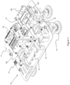
- the rail measuring device (10) the general view of which is given in Figure 1 , basically consists of a table (11), measurement elements provided on the said table (11) and control units.
- a control panel (12), an electric motor (13), and a power source (14) are provided on table (11) to enable the rail measuring device (10) to be operated and controlled.
- Said control panel (12) includes an LCD screen (121) and buttons (122).
- the said LCD screen (121) is the interface of the rail measuring device (10) and provides the data to be displayed by being controlled. Also, by means of a Wi-Fi module (20) located thereon, the interface can be seen from the computer environment and the system parameters can be input via the computer.
- the said buttons (122) are used for enabling the user to set the measurement parameters.
- the movement of the rail measuring device (10) on the rail is provided by the said electric motor (13).
- the said power source (14) is the configuration in which the rail measuring device (10) meets all its power. Li-Ion battery is preferably used as the power source (14).
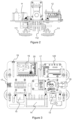
- the measurement elements located in the rail measuring device (10) can be seen in detail in Figure 3 .
- Corresponding measurement elements consist of an encoder (15), a microprocessor (16), an angle sensor (17), and an object sensor (18) provided on table (11).
- the said encoder (15) is used to measure how far the rail measuring device (10) has traveled on the rail and to receive the displacement data. Irregular heights and lateral shifts on the rails are detected by means of the said angle sensor (17).
- the angle sensor can be selected as a tilt sensor or an IMU sensor with DMP (Digital Motion Processor) property.
- IFM brand and JN2101 model sensors are used as tilt sensors.
- Bosch brand and BNO055 model sensor is preferably used as IMU sensor.
- the said object sensor (18) provides that the rail measuring device (10) is stopped when there is an undesired object on the rail.
- the said microprocessor (16) contains an acceleration sensor in its structure and detects the first angle of the rail by means of this acceleration sensor and angle sensor (17).
- the microprocessor (16) controls the rail measuring device (10) and is used to verify the initial angle data and the data from the angle sensor (17).
- a microprocessor (16) of the STM32 type is preferably used in the rail measuring device (10).
- the user When the rail measuring device (10) is first switched on, the user first inputs the measurement amount (how many measurements will be taken) and the measurement frequency value (how many mm intervals the measurement will be made) into the system via the buttons (122) on the control panel (12) or by means of the Wi-Fi module (20) on a computer. Inputting the measurement frequency value high increases the accuracy of the measurements made. For example, when the measurement is made by an angle sensor (17) with a resolution of 0.01 degrees and an encoder (15) giving 800 ticks at 100 mm intervals, the accuracy becomes 0.02 mm.
- the angle sensor (17) regards the angle value of the rail measuring device (10) as 0 degrees prior to the operation. Each angle change that occurs after the device starts to operate is also read by the angle sensor (17).
- the movement of the rail measuring device (10) on the rail takes place as much as the measurement frequency. Electric motor (13) ensures that the device moves to the targeted point on the rail.
- the distance traveled is detected by the encoder (15). The accuracy of the movement varies according to the diameter of the contact wheel (112) and the resolution of the encoder (15).
- the angle value is read by the microprocessor (16) and the angle sensor (17).
- the rail measuring device (10) continues the measurement process until the targeted amount of measurements is reached and stops when the target is reached.
- the rail measuring device of the invention can perform measurements with at least 50 times higher resolution than its equivalents, without range and line of sight limits.
- the angle sensor used the measurements of high accuracy can be performed, preferably up to a maximum of 0.02 mm.
- the angle sensor (17) is much cheaper than its equivalents and the related production costs of the device are lower.
- measurements can be performed using low energy, and up to 5 times lower energy consumption than its equivalents.
- Trial tests were carried out to ensure that the rail measuring device (10) is tested and calibrated. Trial tests were performed on a test rail. Said test rail was composed of 11 m long 50 ⁇ 50 mm square rail. The position data of the rail was detected by first making measurements with a coordinate measuring machine on the test rail. The graph showing the position data of the rail is shown in Graph 1 below.
- the rail measuring device (10) After determining the position data of the test rail, the rail measuring device (10) is positioned at the beginning of the test rail. For the trial test, the number of measurements is 100 and the measurement frequency is 100 mm. The rail measuring device (10) is 350 mm long. Therefore, when positioned on the rail, the length of 175 mm from the beginning of the rail is not included in the measurement. Also, the rail measuring device (10) takes the first measurement value after it has moved 75 mm on the rail upon being fully seated on the rail. Thus, the first measuring point is 250 mm from the starting point of the rail. The measurement results performed with the rail measuring device (10) as well as the position data thereof are shown in Graphic 2 below.
- the maximum error was measured as 0.33 mm and the average error was measured as 0.18 mm.
- the angle accuracy read when the measurement was performed was +- 0.1 degrees.
- the standard deviation of the errors was obtained as 0.0786.
Landscapes
- Engineering & Computer Science (AREA)
- Mechanical Engineering (AREA)
- Automation & Control Theory (AREA)
- Physics & Mathematics (AREA)
- General Physics & Mathematics (AREA)
- Length Measuring Devices With Unspecified Measuring Means (AREA)
Claims (12)
- Kranschienenmessvorrichtung (10) zum Detektieren der unregelmäßigen Höhen und seitlichen Verschiebungen in den Schienen, indem sie auf der Kranschiene mit Energie, die durch eine Leistungsquelle (14) bereitgestellt wird, und Antrieb von einem Elektromotor (13) bewegt wird, dadurch gekennzeichnet, dass sie Folgendes umfasst; mindestens einen Winkelsensor (17), der die Winkeländerung der Schiene detektiert, einen Codierer (15), um zu messen, wie weit die Schienenmessvorrichtung (10) auf der Schiene gefahren ist, und um die Verlagerungsdaten zu empfangen, und einen Mikroprozessor (16), der die Daten von den Sensoren steuert, indem er die Schienenmessvorrichtung (10) steuert.
- Schienenmessvorrichtung (10) nach Anspruch 1, dadurch gekennzeichnet, dass sie Folgendes umfasst; einen Objektsensor (18), der ermöglicht, dass die Schienenmessvorrichtung (10) angehalten wird, wenn sich ein unerwünschtes Objekt auf der Schiene befindet.
- Schienenmessvorrichtung (10) nach Anspruch 1, dadurch gekennzeichnet, dass der Mikroprozessor (16) einen Beschleunigungssensor zum Detektieren des ersten Winkels der Schiene umfasst.
- Schienenmessvorrichtung (10) nach Anspruch 1, dadurch gekennzeichnet, dass sie Folgendes umfasst; eine USB-Verbindung (19) zum Übertragen der durch den Winkelsensor (17), den Codierer (15) und den Mikroprozessor (16) detektierten Informationen zu Winkelwerten und gefahrener Strecke an die externe Umgebung.
- Schienenmessvorrichtung (10) nach Anspruch 1, dadurch gekennzeichnet, dass sie Folgendes umfasst; ein Wi-Fi-Modul (21) zum Übertragen der durch den Winkelsensor (17), den Codierer (15) und den Mikroprozessor (16) detektierten Informationen zu Winkelwerten und gefahrener Strecke an die externe Umgebung.
- Schienenmessvorrichtung (10) nach Anspruch 1, dadurch gekennzeichnet, dass der Winkelsensor (17) ein Neigungssensor oder ein IMU-Sensor ist.
- Schienenmessvorrichtung (10) nach Anspruch 1, dadurch gekennzeichnet, dass die Leistungsquelle (14) bevorzugt eine Li-Ionen-Batterie ist.
- Schienenmessvorrichtung (10) nach Anspruch 1, dadurch gekennzeichnet, dass der Elektromotor (13) bevorzugt ein Gleichstrommotor ist.
- Kranschienenmessverfahren zum Detektieren der unregelmäßigen Höhen und seitlichen Verschiebungen in den Schienen mit der Kranschienenmessvorrichtung nach einem der vorhergehenden Ansprüche, indem sie auf der Kranschiene mit Energie, die durch eine Leistungsquelle (14) bereitgestellt wird, und Antrieb von einem Elektromotor (13) bewegt wird, dadurch gekennzeichnet, dass es die folgenden Schritte umfasst:a) Eingeben der Anzahl von Messungen und Messfrequenzdaten in die Schienenmessvorrichtung (10) über Tasten (112) durch ein Bedienfeld (12),b) Eingeben der Anzahl und Häufigkeit von Messungen aus der Computerumgebung in die Schienenmessvorrichtung (10) mittels des Wi-Fi-Moduls (20),c) Detektieren der Kranschienenwinkeländerung mit einem Winkelsensor (17),d) Detektieren der auf der Kranschiene gefahrenen Strecke mittels eines Codierers (15),e) Übertragen der Informationen zu Winkeldaten und gefahrener Strecke über eine USB-Verbindung (19) an USB,f) Übertragen der Informationen zu Winkeldaten und gefahrener Strecke über ein Wi-Fi-Modul (20) an die Computerumgebung,g) Verarbeiten der auf USB geschriebenen oder über Wi-Fi übertragenen Daten gemäß einem mathematischen Modell, um die Werte der Höhenänderung und seitlichen Änderung zu berechnen.
- Schienenmessverfahren nach Anspruch 9, dadurch gekennzeichnet, dass die ersten Winkeldaten auf der Schiene durch einen in einem Mikroprozessor (16) angeordneten Beschleunigungssensor detektiert werden.
- Schienenmessverfahren nach Anspruch 9, dadurch gekennzeichnet, dass, falls ein IMU-Sensor als der Winkelsensor (17) verwendet wird, die ersten Winkeldaten auf der Schiene durch einen in dem IMU-Sensor angeordneten Beschleunigungssensor detektiert werden.
- Schienenmessverfahren nach Anspruch 9, dadurch gekennzeichnet, dass die Messung bevorzugt mit einer maximalen Genauigkeit von 0,02 mm mit dem Winkelsensor (17) durchgeführt wird.
Applications Claiming Priority (1)
| Application Number | Priority Date | Filing Date | Title |
|---|---|---|---|
| PCT/TR2021/050691 WO2023282859A1 (en) | 2021-07-07 | 2021-07-07 | Crane rail measuring device |
Publications (3)
| Publication Number | Publication Date |
|---|---|
| EP4139630A1 EP4139630A1 (de) | 2023-03-01 |
| EP4139630A4 EP4139630A4 (de) | 2024-02-28 |
| EP4139630B1 true EP4139630B1 (de) | 2024-11-27 |
Family
ID=84800897
Family Applications (1)
| Application Number | Title | Priority Date | Filing Date |
|---|---|---|---|
| EP21921645.4A Active EP4139630B1 (de) | 2021-07-07 | 2021-07-07 | Kranschienenmessvorrichtung |
Country Status (2)
| Country | Link |
|---|---|
| EP (1) | EP4139630B1 (de) |
| WO (1) | WO2023282859A1 (de) |
Family Cites Families (10)
| Publication number | Priority date | Publication date | Assignee | Title |
|---|---|---|---|---|
| JPH05264261A (ja) * | 1992-03-19 | 1993-10-12 | Hitachi Kiden Kogyo Ltd | クレーンレールのうねり、高低差測定装置 |
| JP3306168B2 (ja) * | 1993-05-11 | 2002-07-24 | 日立機電工業株式会社 | レール変位及び摩耗測定装置 |
| JP4782048B2 (ja) | 2007-03-13 | 2011-09-28 | 新日本製鐵株式会社 | 天井クレーンレールの測量方法及び管理方法 |
| CN103063146B (zh) | 2013-01-16 | 2015-08-05 | 上海市特种设备监督检验技术研究院 | 一种起重机轨道测量检测系统 |
| KR101462344B1 (ko) | 2013-05-03 | 2014-11-14 | 주식회사 포스코 | 천정 크레인의 주행레일의 주행 직진도 진단장치 및 진단방법 |
| DE102014100653B4 (de) | 2014-01-21 | 2016-01-21 | fos4X GmbH | Schienenmesssystem |
| CN104061887B (zh) * | 2014-06-18 | 2017-06-16 | 温州市特种设备检测中心 | 测量起重机轨道的检测车 |
| JP2020126020A (ja) * | 2019-02-06 | 2020-08-20 | 住友重機械搬送システム株式会社 | レール計測装置 |
| JP3222202U (ja) * | 2019-04-19 | 2019-07-18 | ベステラ株式会社 | クレーンレール検査システム |
| US11506565B2 (en) | 2019-09-24 | 2022-11-22 | Falk PLI Engineering & Surveying, Inc. | Four-dimensional crane rail measurement |
-
2021
- 2021-07-07 WO PCT/TR2021/050691 patent/WO2023282859A1/en not_active Ceased
- 2021-07-07 EP EP21921645.4A patent/EP4139630B1/de active Active
Also Published As
| Publication number | Publication date |
|---|---|
| WO2023282859A1 (en) | 2023-01-12 |
| EP4139630A1 (de) | 2023-03-01 |
| EP4139630A4 (de) | 2024-02-28 |
Similar Documents
| Publication | Publication Date | Title |
|---|---|---|
| US9638507B2 (en) | Measurement machine utilizing a barcode to identify an inspection plan for an object | |
| US10378889B2 (en) | Measurement system having a cooperative robot and three-dimensional imager | |
| JP4857369B2 (ja) | 分岐器検査装置 | |
| EP2788714A1 (de) | Koordinatenmessmaschine mit einer kamera | |
| GB2075185A (en) | Dimensional checking apparatus | |
| JP7227442B2 (ja) | 車両寸法測定装置及び車両寸法測定方法 | |
| CN104655024A (zh) | 一种影像测量设备及其快速准确测高装置与方法 | |
| CN103033136B (zh) | 激光光学确定铸坯导辊的高度的探头、系统及方法 | |
| US10513039B2 (en) | Teach pendant and robot system provided with the same | |
| EP4139630B1 (de) | Kranschienenmessvorrichtung | |
| JP2005121370A (ja) | 表面形状測定装置および表面形状測定方法 | |
| US20060243035A1 (en) | Surface roughness/contour profile measuring instrument | |
| JP6500560B2 (ja) | 光学式センサーの校正方法、及び三次元座標測定機 | |
| CN101113891B (zh) | 光学式测量装置 | |
| CN114030504A (zh) | 一种轨道检查仪的轨道参数测算系统及测算方法 | |
| JP7200780B2 (ja) | 情報処理装置、情報処理方法、及び情報処理システム | |
| JPH0123041B2 (de) | ||
| CN113029019A (zh) | 一种用于高压电气设备的零件间隙测量装置及方法 | |
| JP2579726B2 (ja) | 接触式プローブ | |
| CN113387274B (zh) | 集卡车对位方法、系统及集装箱起重机 | |
| US20220343527A1 (en) | Tire groove measurement device and tire groove measurement method | |
| JP4533050B2 (ja) | 表面形状測定装置および表面形状測定方法 | |
| CN119043182A (zh) | 三维空间光学跟踪测量系统 | |
| JPH09243304A (ja) | 形状測定装置、及びそれを用いた被測定面の位置決め方法 | |
| JP2002122423A (ja) | 三次元測定方法 |
Legal Events
| Date | Code | Title | Description |
|---|---|---|---|
| STAA | Information on the status of an ep patent application or granted ep patent |
Free format text: STATUS: UNKNOWN |
|
| STAA | Information on the status of an ep patent application or granted ep patent |
Free format text: STATUS: THE INTERNATIONAL PUBLICATION HAS BEEN MADE |
|
| PUAI | Public reference made under article 153(3) epc to a published international application that has entered the european phase |
Free format text: ORIGINAL CODE: 0009012 |
|
| STAA | Information on the status of an ep patent application or granted ep patent |
Free format text: STATUS: REQUEST FOR EXAMINATION WAS MADE |
|
| 17P | Request for examination filed |
Effective date: 20220930 |
|
| AK | Designated contracting states |
Kind code of ref document: A1 Designated state(s): AL AT BE BG CH CY CZ DE DK EE ES FI FR GB GR HR HU IE IS IT LI LT LU LV MC MK MT NL NO PL PT RO RS SE SI SK SM TR |
|
| A4 | Supplementary search report drawn up and despatched |
Effective date: 20240125 |
|
| RIC1 | Information provided on ipc code assigned before grant |
Ipc: B66C 15/00 20060101ALI20240119BHEP Ipc: B66C 7/00 20060101ALI20240119BHEP Ipc: B66C 13/46 20060101ALI20240119BHEP Ipc: B61K 9/08 20060101ALI20240119BHEP Ipc: G01B 11/24 20060101ALI20240119BHEP Ipc: G01B 21/16 20060101AFI20240119BHEP |
|
| GRAP | Despatch of communication of intention to grant a patent |
Free format text: ORIGINAL CODE: EPIDOSNIGR1 |
|
| STAA | Information on the status of an ep patent application or granted ep patent |
Free format text: STATUS: GRANT OF PATENT IS INTENDED |
|
| RIC1 | Information provided on ipc code assigned before grant |
Ipc: B66C 15/00 20060101ALI20240523BHEP Ipc: B66C 7/00 20060101ALI20240523BHEP Ipc: B66C 13/46 20060101ALI20240523BHEP Ipc: B61K 9/08 20060101ALI20240523BHEP Ipc: G01B 11/24 20060101ALI20240523BHEP Ipc: G01B 21/16 20060101AFI20240523BHEP |
|
| INTG | Intention to grant announced |
Effective date: 20240621 |
|
| DAV | Request for validation of the european patent (deleted) | ||
| DAX | Request for extension of the european patent (deleted) | ||
| GRAS | Grant fee paid |
Free format text: ORIGINAL CODE: EPIDOSNIGR3 |
|
| GRAA | (expected) grant |
Free format text: ORIGINAL CODE: 0009210 |
|
| STAA | Information on the status of an ep patent application or granted ep patent |
Free format text: STATUS: THE PATENT HAS BEEN GRANTED |
|
| AK | Designated contracting states |
Kind code of ref document: B1 Designated state(s): AL AT BE BG CH CY CZ DE DK EE ES FI FR GB GR HR HU IE IS IT LI LT LU LV MC MK MT NL NO PL PT RO RS SE SI SK SM TR |
|
| REG | Reference to a national code |
Ref country code: GB Ref legal event code: FG4D |
|
| REG | Reference to a national code |
Ref country code: CH Ref legal event code: EP |
|
| REG | Reference to a national code |
Ref country code: DE Ref legal event code: R096 Ref document number: 602021022659 Country of ref document: DE |
|
| REG | Reference to a national code |
Ref country code: IE Ref legal event code: FG4D |
|
| REG | Reference to a national code |
Ref country code: LT Ref legal event code: MG9D |
|
| REG | Reference to a national code |
Ref country code: NL Ref legal event code: MP Effective date: 20241127 |
|
| PG25 | Lapsed in a contracting state [announced via postgrant information from national office to epo] |
Ref country code: IS Free format text: LAPSE BECAUSE OF FAILURE TO SUBMIT A TRANSLATION OF THE DESCRIPTION OR TO PAY THE FEE WITHIN THE PRESCRIBED TIME-LIMIT Effective date: 20250327 Ref country code: HR Free format text: LAPSE BECAUSE OF FAILURE TO SUBMIT A TRANSLATION OF THE DESCRIPTION OR TO PAY THE FEE WITHIN THE PRESCRIBED TIME-LIMIT Effective date: 20241127 Ref country code: PT Free format text: LAPSE BECAUSE OF FAILURE TO SUBMIT A TRANSLATION OF THE DESCRIPTION OR TO PAY THE FEE WITHIN THE PRESCRIBED TIME-LIMIT Effective date: 20250327 |
|
| PG25 | Lapsed in a contracting state [announced via postgrant information from national office to epo] |
Ref country code: FI Free format text: LAPSE BECAUSE OF FAILURE TO SUBMIT A TRANSLATION OF THE DESCRIPTION OR TO PAY THE FEE WITHIN THE PRESCRIBED TIME-LIMIT Effective date: 20241127 Ref country code: NL Free format text: LAPSE BECAUSE OF FAILURE TO SUBMIT A TRANSLATION OF THE DESCRIPTION OR TO PAY THE FEE WITHIN THE PRESCRIBED TIME-LIMIT Effective date: 20241127 |
|
| REG | Reference to a national code |
Ref country code: AT Ref legal event code: MK05 Ref document number: 1746073 Country of ref document: AT Kind code of ref document: T Effective date: 20241127 |
|
| PG25 | Lapsed in a contracting state [announced via postgrant information from national office to epo] |
Ref country code: BG Free format text: LAPSE BECAUSE OF FAILURE TO SUBMIT A TRANSLATION OF THE DESCRIPTION OR TO PAY THE FEE WITHIN THE PRESCRIBED TIME-LIMIT Effective date: 20241127 |
|
| PG25 | Lapsed in a contracting state [announced via postgrant information from national office to epo] |
Ref country code: ES Free format text: LAPSE BECAUSE OF FAILURE TO SUBMIT A TRANSLATION OF THE DESCRIPTION OR TO PAY THE FEE WITHIN THE PRESCRIBED TIME-LIMIT Effective date: 20241127 |
|
| PG25 | Lapsed in a contracting state [announced via postgrant information from national office to epo] |
Ref country code: NO Free format text: LAPSE BECAUSE OF FAILURE TO SUBMIT A TRANSLATION OF THE DESCRIPTION OR TO PAY THE FEE WITHIN THE PRESCRIBED TIME-LIMIT Effective date: 20250227 |
|
| PG25 | Lapsed in a contracting state [announced via postgrant information from national office to epo] |
Ref country code: GR Free format text: LAPSE BECAUSE OF FAILURE TO SUBMIT A TRANSLATION OF THE DESCRIPTION OR TO PAY THE FEE WITHIN THE PRESCRIBED TIME-LIMIT Effective date: 20250228 Ref country code: AT Free format text: LAPSE BECAUSE OF FAILURE TO SUBMIT A TRANSLATION OF THE DESCRIPTION OR TO PAY THE FEE WITHIN THE PRESCRIBED TIME-LIMIT Effective date: 20241127 Ref country code: LV Free format text: LAPSE BECAUSE OF FAILURE TO SUBMIT A TRANSLATION OF THE DESCRIPTION OR TO PAY THE FEE WITHIN THE PRESCRIBED TIME-LIMIT Effective date: 20241127 |
|
| PG25 | Lapsed in a contracting state [announced via postgrant information from national office to epo] |
Ref country code: PL Free format text: LAPSE BECAUSE OF FAILURE TO SUBMIT A TRANSLATION OF THE DESCRIPTION OR TO PAY THE FEE WITHIN THE PRESCRIBED TIME-LIMIT Effective date: 20241127 |
|
| PG25 | Lapsed in a contracting state [announced via postgrant information from national office to epo] |
Ref country code: RS Free format text: LAPSE BECAUSE OF FAILURE TO SUBMIT A TRANSLATION OF THE DESCRIPTION OR TO PAY THE FEE WITHIN THE PRESCRIBED TIME-LIMIT Effective date: 20250227 |
|
| PG25 | Lapsed in a contracting state [announced via postgrant information from national office to epo] |
Ref country code: SM Free format text: LAPSE BECAUSE OF FAILURE TO SUBMIT A TRANSLATION OF THE DESCRIPTION OR TO PAY THE FEE WITHIN THE PRESCRIBED TIME-LIMIT Effective date: 20241127 |
|
| PG25 | Lapsed in a contracting state [announced via postgrant information from national office to epo] |
Ref country code: DK Free format text: LAPSE BECAUSE OF FAILURE TO SUBMIT A TRANSLATION OF THE DESCRIPTION OR TO PAY THE FEE WITHIN THE PRESCRIBED TIME-LIMIT Effective date: 20241127 |
|
| PG25 | Lapsed in a contracting state [announced via postgrant information from national office to epo] |
Ref country code: EE Free format text: LAPSE BECAUSE OF FAILURE TO SUBMIT A TRANSLATION OF THE DESCRIPTION OR TO PAY THE FEE WITHIN THE PRESCRIBED TIME-LIMIT Effective date: 20241127 |
|
| PG25 | Lapsed in a contracting state [announced via postgrant information from national office to epo] |
Ref country code: RO Free format text: LAPSE BECAUSE OF FAILURE TO SUBMIT A TRANSLATION OF THE DESCRIPTION OR TO PAY THE FEE WITHIN THE PRESCRIBED TIME-LIMIT Effective date: 20241127 |
|
| PG25 | Lapsed in a contracting state [announced via postgrant information from national office to epo] |
Ref country code: SK Free format text: LAPSE BECAUSE OF FAILURE TO SUBMIT A TRANSLATION OF THE DESCRIPTION OR TO PAY THE FEE WITHIN THE PRESCRIBED TIME-LIMIT Effective date: 20241127 |
|
| PG25 | Lapsed in a contracting state [announced via postgrant information from national office to epo] |
Ref country code: CZ Free format text: LAPSE BECAUSE OF FAILURE TO SUBMIT A TRANSLATION OF THE DESCRIPTION OR TO PAY THE FEE WITHIN THE PRESCRIBED TIME-LIMIT Effective date: 20241127 |
|
| PG25 | Lapsed in a contracting state [announced via postgrant information from national office to epo] |
Ref country code: IT Free format text: LAPSE BECAUSE OF FAILURE TO SUBMIT A TRANSLATION OF THE DESCRIPTION OR TO PAY THE FEE WITHIN THE PRESCRIBED TIME-LIMIT Effective date: 20241127 |
|
| REG | Reference to a national code |
Ref country code: DE Ref legal event code: R097 Ref document number: 602021022659 Country of ref document: DE |
|
| PG25 | Lapsed in a contracting state [announced via postgrant information from national office to epo] |
Ref country code: SE Free format text: LAPSE BECAUSE OF FAILURE TO SUBMIT A TRANSLATION OF THE DESCRIPTION OR TO PAY THE FEE WITHIN THE PRESCRIBED TIME-LIMIT Effective date: 20241127 |
|
| PLBE | No opposition filed within time limit |
Free format text: ORIGINAL CODE: 0009261 |
|
| STAA | Information on the status of an ep patent application or granted ep patent |
Free format text: STATUS: NO OPPOSITION FILED WITHIN TIME LIMIT |
|
| 26N | No opposition filed |
Effective date: 20250828 |