EP4136019B1 - Riemen und verfahren zur verminderung des rumpfs eines schwimmenden schiffes - Google Patents
Riemen und verfahren zur verminderung des rumpfs eines schwimmenden schiffes Download PDFInfo
- Publication number
- EP4136019B1 EP4136019B1 EP21725391.3A EP21725391A EP4136019B1 EP 4136019 B1 EP4136019 B1 EP 4136019B1 EP 21725391 A EP21725391 A EP 21725391A EP 4136019 B1 EP4136019 B1 EP 4136019B1
- Authority
- EP
- European Patent Office
- Prior art keywords
- belt
- hull
- air
- vessel
- previous
- Prior art date
- Legal status (The legal status is an assumption and is not a legal conclusion. Google has not performed a legal analysis and makes no representation as to the accuracy of the status listed.)
- Active
Links
Images

Classifications
-
- B—PERFORMING OPERATIONS; TRANSPORTING
- B63—SHIPS OR OTHER WATERBORNE VESSELS; RELATED EQUIPMENT
- B63B—SHIPS OR OTHER WATERBORNE VESSELS; EQUIPMENT FOR SHIPPING
- B63B1/00—Hydrodynamic or hydrostatic features of hulls or of hydrofoils
- B63B1/32—Other means for varying the inherent hydrodynamic characteristics of hulls
- B63B1/34—Other means for varying the inherent hydrodynamic characteristics of hulls by reducing surface friction
- B63B1/38—Other means for varying the inherent hydrodynamic characteristics of hulls by reducing surface friction using air bubbles or air layers gas filled volumes
- B63B2001/387—Other means for varying the inherent hydrodynamic characteristics of hulls by reducing surface friction using air bubbles or air layers gas filled volumes using means for producing a film of air or air bubbles over at least a significant portion of the hull surface
-
- Y—GENERAL TAGGING OF NEW TECHNOLOGICAL DEVELOPMENTS; GENERAL TAGGING OF CROSS-SECTIONAL TECHNOLOGIES SPANNING OVER SEVERAL SECTIONS OF THE IPC; TECHNICAL SUBJECTS COVERED BY FORMER USPC CROSS-REFERENCE ART COLLECTIONS [XRACs] AND DIGESTS
- Y02—TECHNOLOGIES OR APPLICATIONS FOR MITIGATION OR ADAPTATION AGAINST CLIMATE CHANGE
- Y02T—CLIMATE CHANGE MITIGATION TECHNOLOGIES RELATED TO TRANSPORTATION
- Y02T70/00—Maritime or waterways transport
- Y02T70/10—Measures concerning design or construction of watercraft hulls
Definitions
- the present invention concerns a belt for reducing the drag of a hull of a floating vessel in accordance with the preamble of claim 1.
- a belt for reducing the drag of a hull of a floating vessel in accordance with the preamble of claim 1.
- Such a device is disclosed in KR 101 802 231 B1 .
- the invention aims to solve these problems and therefore provides for a belt for reducing the drag of a hull of a floating vessel, whereby the belt comprises a belt body extending in a length direction, whereby the belt comprises, in the length direction, a sequence of bubble generators which are embedded in the belt body, whereby the belt comprises an air channel for supplying pressurised air to the bubble generators, whereby the air channel extends in the length direction, whereby the bubble generators are connected to the air channel, whereby the belt body is made of an elastic and flexible material.
- Such a belt can easily be placed around part of the hull, in particular the underside, and possibly also the sides, of the hull, and then tensioned to be kept in place. Due to its flexibility it will thereby follow the shape of the hull and sit tightly against the hull.
- such a belt can also be removed again by releasing the tension and then be reused on another vessel.
- Such a belt is therefore particularly suited to equip a vessel with air lubrication possibilities if a practical opportunity, i.e. a major maintenance, to install a permanent air lubrication system is not available, or if the vessel is mainly used in a single location and only occasionally needs to be moved to another, far away location.
- KR20170000711 discloses a belt including a separated air injection pipe comprising an air provider to produce and provide air; an air providing pipe into which the air discharged from the air provider flows; and a separated air injection pipe, which has a plurality of air injection holes formed on one side thereof.
- WO2005/122676 discloses a bubble-generating device consisting of a multi-cell system which is affixed to the walls of the hull of the boat and which is equipped with at least one main circulation shaft which is traversed by a first conduit for pressurised water and a second conduit for a pressurised gas, said two conduits supplying multiple bubble-releasing cells.
- US2011/259257 discloses an apparatus for reducing the drag that a vessel hull experiences when moving through the water by interposing air bubbles between the hull and the stream of water that the vessel is moving through by delivering compressed air to the bottom of the vessel.
- US2011/214762 discloses A flow tube for a bidirectional flow meter comprising a first means for generating a periodic pressure fluctuation whose frequency varies in dependence on the flow rate of fluid through the meter in a first direction; and a second means for generating a periodic pressure fluctuation whose frequency varies in dependence on the flow rate of fluid through the meter in a second direction, opposite to the first direction; wherein said first and second generating means are connected in series between an inlet port and an outlet port.
- US7080664 discloses a fluid amplifier comprising at least one control valve having a movable element for selectively opening and closing at least one of a first control stream channel and a second control fluid flow channel, wherein the control valve also includes a diaphragm for isolating the moveable element.
- the air channel is fully enclosed in the belt body, so that it cannot easily get damaged.
- the air channel is formed as a channel-shaped cavity in the material of the belt body.
- the belt comprises at least one tensioning cable for tensioning the belt around a hull of a floating vessel, whereby preferably the tensioning cable is fully embedded in the belt body to avoid damage.
- Such a tensioning cable allows large tensioning forces to be applied, so that the belt remains well in place during use.
- the belt comprises magnets which are embedded in the belt body, whereby the magnets are magnets for attaching the belt to a metallic hull of a floating vessel.
- Such magnets can be used as a fastening mechanism, alternatively to tensioning, but preferably in addition to tensioning, whereby the magnets are particularly useful for attaching the belt to the hull during installation and positioning it, before tension is applied.
- the bubble generators are fluidic oscillators for generating one or more pulsating air flows from a constant air flow. These allow control over the bubble size and bubble spacing, so that coalescence of bubbles can be reduced.
- the invention further concerns a device for reducing the drag of a hull of a floating vessel, comprising a belt according to any of the previous claims and a tensioning device for tensioning the belt at least partly around the hull of a floating vessel.
- the device comprises a tension monitoring system capable of generating an status signal indicating a tension subceeding a first desired critical tension and/or exceeding a second critical tension.
- a tension monitoring system capable of generating an status signal indicating a tension subceeding a first desired critical tension and/or exceeding a second critical tension.
- the range between the first critical tension and the second critical tension is a desired range for the tension, allowing normal use of the belt.
- Such a status signal may be any type of signal, for instance electronic, radio, visual or audible. It may be set to be triggered at a first or second critical tension which is such that the tension needs to be checked and/or adjusted be personnel. In this case it is a warning signal that the tension needs to be checked. It may also be set to be triggered when subceeding a first critical tension at which attachment of the belt to the hull is no longer guaranteed. In this case it acts as an alarm signal to indicates a loss of sufficient tension, which is undesirable as it may result in the belt becoming detached from the hull. It may also be set to be triggered at a when exceeding a second critical tension which is an indication that the belt has snagged behind an obstacle. In this case it also acts as an alarm signal.
- a first or second critical tension which is such that the tension needs to be checked and/or adjusted be personnel. In this case it is a warning signal that the tension needs to be checked. It may also be set to be triggered when subceeding a first critical tension at which
- the device comprises a source of pressurised air which is connected to the air channel, whereby the tension monitoring system is connected to the source of pressurised air, whereby the device is arranged such that an occurrence of said status signal causes the source of pressurised air to cease provision of pressurised air.
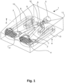
- the invention further concerns a method of reducing the drag of a hull of a floating vessel using a belt or a device according to the invention, whereby the belt is installed under the hull, whereby pressurised air is supplied to the air channel.
- the belt comprises magnets which are embedded in the belt body, whereby the belt, in a non-tensioned state, is first attached to the hull by means of the magnets, whereby afterwards the belt is tensioned against the hull, whereby during use of the belt tension is maintained.
- it is a method of temporarily reducing said drag, whereby said belt is removed after being used to reduce said drag, and preferably rolled up for storage and/or used on another vessel.
- the vessel is a vessel which is being towed by another vessel.
- the methods is focused on equipping vessels which are only occasionally making long voyages, eg international voyages across oceans, and which may not even have sufficient on board propulsion capabilities for such long voyages, with an air lubrication system.
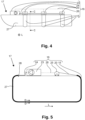
- the oscillator 1 of figures 1 to 3 is a traditional fluidic oscillator, of which the air outlets 2,3 are provided with perforated plates 4 with fifty round holes of 1.7mm diameter each.
- the oscillator 1 comprises a air inlet 5 and an air inlet channel 6 leading away from the air inlet 5.
- the air inlet channel 6 widens and diverges into two air outlet channels, more specifically a first outlet channel 7 and a second outlet channel 8 which lead to the two aforementioned air outlets 2,3, more specifically to a first air outlet 2 and to a second air outlet 3, which are provided with said perforated plates 4.
- the two outlet channels 7, 8 are separated by a splitter 9 with a concave nose 10.
- the splitter 9 and the air inlet channel 6 and the outlet channels 7, 8 jointly constitute a bistable fluidic amplifier arranged to amplify control signals, whereby in this case the control signals are fed to the fluidic amplifier via a first control port 11 and a second control port 12.
- the oscillator 1 works as follows: A constant airflow is established at the air inlet 5 and through the air inlet channel 6. This airflow will either flow through the first outlet channel 7 or through the second outlet channel 8, but not through both at the same time. If undisturbed, the air will continue to flow this way because of the Coanda-effect, which enhances the tendency for a fluid to follow a curved surface.
- the transition from the air inlet channel 6 to each of the outlet channels 7, 8 is such a curved surface.
- the concave nose 10 of the splitter 9 helps to create an induced secondary airflow that further stabilises the airflow through that particular outlet channel 7,8.
- the compressor 23 is arranged to shut off as a safety measure if an alarm signal is detected.
Landscapes
- Physics & Mathematics (AREA)
- Fluid Mechanics (AREA)
- Ocean & Marine Engineering (AREA)
- Engineering & Computer Science (AREA)
- Combustion & Propulsion (AREA)
- Mechanical Engineering (AREA)
- Chemical & Material Sciences (AREA)
- Filling Or Discharging Of Gas Storage Vessels (AREA)
- Structure Of Belt Conveyors (AREA)
- Aeration Devices For Treatment Of Activated Polluted Sludge (AREA)
- Measuring Volume Flow (AREA)
- Other Liquid Machine Or Engine Such As Wave Power Use (AREA)
- Belt Conveyors (AREA)
- Indicating Or Recording The Presence, Absence, Or Direction Of Movement (AREA)
- Devices For Conveying Motion By Means Of Endless Flexible Members (AREA)
Claims (14)
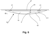
- Gurt (15) zum Verringern des Strömungswiderstands eines Rumpfs (27) eines schwimmenden Wasserfahrzeugs (17), wodurch der Gurt (15) einen Gurtkörper (18) umfasst, der sich in einer Längsrichtung (L) erstreckt, wodurch der Gurt (15) eine Folge von Blasenerzeugern (1) umfasst, die in dem Gurtkörper (18) eingebettet sind, wodurch der Gurt (15) einen Luftkanal (19) zum Zuführen von Druckluft zu den Blasenerzeugern (1) umfasst, wodurch sich der Luftkanal (19) in der Längsrichtung (L) erstreckt, wodurch die Blasenerzeuger (1) mit dem Luftkanal (19) verbunden sind, wobei der Gurtkörper (18) aus einem flexiblen Material besteht, dadurch gekennzeichnet, dass der Gurt (15) mindestens ein Spannseil (20) zum Spannen des Gurts (15) um den Rumpf (27) des schwimmenden Wasserfahrzeugs (17) umfasst.
- Gurt (15) nach Anspruch 1, dadurch gekennzeichnet, dass der Luftkanal (19) vollständig in dem Gurtkörper (18) umschlossen ist.
- Gurt (15) nach einem der vorhergehenden Ansprüche, dadurch gekennzeichnet, dass der Gurtkörper (18) aus Gummi oder einem elastischen Kunststoff besteht.
- Gurt (15) nach einem der vorhergehenden Ansprüche, dadurch gekennzeichnet, dass das Spannseil (20) vollständig in dem Gurtkörper (18) eingebettet ist.
- Gurt (15) nach einem der vorhergehenden Ansprüche, dadurch gekennzeichnet, dass das Spannseil (20) aus Stahl und/oder Aramidfasern und/oder Polypropylenfasern besteht.
- Gurt (15) nach einem der vorhergehenden Ansprüche, dadurch gekennzeichnet, dass der Gurt (15) Magneten (21) umfasst, die in dem Gurtkörper (18) eingebettet sind, wodurch die Magneten Magneten (21) zum Befestigen des Gurts (15) an einem metallischen Rumpf (27) eines schwimmenden Wasserfahrzeugs (17) sind.
- Gurt (15) nach einem der vorhergehenden Ansprüche, dadurch gekennzeichnet, dass die Blasenerzeuger Fluidik-Oszillatoren (1) zum Erzeugen eines oder mehrerer pulsierender Luftströme aus einem konstanten Luftstrom sind.
- Vorrichtung (16) zum Verringern des Strömungswiderstands eines Rumpfs (27) eines schwimmenden Wasserfahrzeugs (17), dadurch gekennzeichnet, dass sie einen Gurt (15) nach einem der vorhergehenden Ansprüche und eine Spannvorrichtung (25) zum Spannen des Gurts (15) teilweise oder vollständig um den Rumpf (27) eines schwimmenden Wasserfahrzeugs (17) umfasst.
- Vorrichtung (16) nach Anspruch 8, dadurch gekennzeichnet, dass sie ein Spannungsüberwachungssystem umfasst, das zum Erzeugen eines Zustandssignals in der Lage ist, das ein Spannungszustandssignal angibt, das eine Spannung angibt, die außerhalb eines gewünschten Bereichs liegt.
- Vorrichtung (16) nach einem der vorhergehenden Ansprüche, dadurch gekennzeichnet, dass sie eine Quelle (23) von Druckluft umfasst, die mit dem Luftkanal (19) verbunden ist.
- Vorrichtung (16) nach Anspruch 9 und 10, dadurch gekennzeichnet, dass das Spannungsüberwachungssystem mit der Quelle (23) von Druckluft verbunden ist, wodurch die Vorrichtung (16) derart angeordnet ist, dass ein Auftreten des Zustandssignals bewirkt, dass die Quelle von Druckluft die Bereitstellung von Druckluft einstellt.
- Verfahren zum Verringern des Strömungswiderstands eines Rumpfs (27) eines schwimmenden Wasserfahrzeugs (17) unter Verwendung eines Gurts (15) nach einem der Ansprüche 1 bis 7 oder Vorrichtung (16) nach einem der Ansprüche 8 bis 11, wodurch der Gurt (15) unter dem Rumpf (27) installiert ist, wodurch dem Luftkanal (19) Druckluft zugeführt wird.
- Verfahren nach Anspruch 12, wodurch der Gurt (15) ein Gurt (15) nach Anspruch 6 ist, wodurch der Gurt (15), in einem nicht-gespannten Zustand, zuerst mit Hilfe der Magneten (21) an dem Rumpf (27) befestigt wird, wodurch danach der Gurt (15) gegen den Rumpf (27) gespannt wird, wodurch während der Verwendung des Gurts (15) eine Spannung aufrechterhalten wird.
- Verfahren nach Anspruch 12 oder 13, wobei das Wasserfahrzeug (17) ein Wasserfahrzeug (17) ist, das durch ein anderes Wasserfahrzeug geschleppt wird.
Applications Claiming Priority (2)
| Application Number | Priority Date | Filing Date | Title |
|---|---|---|---|
| EP20170189.3A EP3895974A1 (de) | 2020-04-17 | 2020-04-17 | Riemen und verfahren zur verminderung des rumpfs eines schwimmenden schiffes |
| PCT/EP2021/060042 WO2021209639A1 (en) | 2020-04-17 | 2021-04-19 | Belt and method for reducing the drag of a hull of a floating vessel. |
Publications (3)
| Publication Number | Publication Date |
|---|---|
| EP4136019A1 EP4136019A1 (de) | 2023-02-22 |
| EP4136019B1 true EP4136019B1 (de) | 2025-02-26 |
| EP4136019C0 EP4136019C0 (de) | 2025-02-26 |
Family
ID=70333781
Family Applications (2)
| Application Number | Title | Priority Date | Filing Date |
|---|---|---|---|
| EP20170189.3A Withdrawn EP3895974A1 (de) | 2020-04-17 | 2020-04-17 | Riemen und verfahren zur verminderung des rumpfs eines schwimmenden schiffes |
| EP21725391.3A Active EP4136019B1 (de) | 2020-04-17 | 2021-04-19 | Riemen und verfahren zur verminderung des rumpfs eines schwimmenden schiffes |
Family Applications Before (1)
| Application Number | Title | Priority Date | Filing Date |
|---|---|---|---|
| EP20170189.3A Withdrawn EP3895974A1 (de) | 2020-04-17 | 2020-04-17 | Riemen und verfahren zur verminderung des rumpfs eines schwimmenden schiffes |
Country Status (6)
| Country | Link |
|---|---|
| US (1) | US12497135B2 (de) |
| EP (2) | EP3895974A1 (de) |
| JP (1) | JP7541109B2 (de) |
| KR (1) | KR20230002644A (de) |
| CN (1) | CN115943106B (de) |
| WO (1) | WO2021209639A1 (de) |
Families Citing this family (7)
| Publication number | Priority date | Publication date | Assignee | Title |
|---|---|---|---|---|
| WO2022150850A1 (en) * | 2021-01-11 | 2022-07-14 | Parker Maritime Technologies, LLC | Methods, systems, and apparatuses to facilitate providing and sustaining a laminar flow of a fluid across a vessel |
| USD1054011S1 (en) | 2021-02-22 | 2024-12-10 | Parker Maritime Technologies, LLC | Air dispersal unit |
| US12049285B2 (en) * | 2021-07-21 | 2024-07-30 | Parker Maritime Technologies, LLC | Transverse hydro-laminar flow system |
| NL2030857B1 (en) * | 2022-02-09 | 2023-09-07 | Alfa Laval Rotterdam B V | A method for providing a hull of a vessel with bubble generators |
| CN115258032A (zh) * | 2022-07-12 | 2022-11-01 | 南京理工大学 | 气体射流振荡装置及船舶 |
| DE102023100314B4 (de) * | 2023-01-09 | 2024-09-05 | Universität Rostock, Körperschaft des öffentlichen Rechts | Vorrichtung und Verfahren zur Erhöhung einer Auftriebskraft an einem Schiffsruder mittels aktiver Strömungskontrolle, sowie Schiffsruder |
| US12466525B2 (en) * | 2024-03-22 | 2025-11-11 | Orestis Skoutellas | Chain anchor real-time computing and hydro-mechanics integrated drag identifier |
Family Cites Families (10)
| Publication number | Priority date | Publication date | Assignee | Title |
|---|---|---|---|---|
| WO1988007956A1 (en) * | 1987-04-16 | 1988-10-20 | Allan Donald Thomas | Microbubble injection device for reducing the fluid frictional resistance against a vessel |
| JPH1159562A (ja) * | 1997-08-25 | 1999-03-02 | Kawasaki Heavy Ind Ltd | 船舶用摩擦抵抗低減装置 |
| US6145459A (en) | 1997-12-19 | 2000-11-14 | Ishikawajima-Harima Heavy Industries Co., Ltd. | Friction-reducing ship and method for reducing skin friction |
| WO2005122676A2 (es) * | 2004-06-11 | 2005-12-29 | Universidad De Sevilla | Dispositivo generador de burbujas para la reducción de fricción en el casco de embarcaciones |
| US7080664B1 (en) * | 2005-05-20 | 2006-07-25 | Crystal Fountains Inc. | Fluid amplifier with media isolation control valve |
| GB2463488A (en) * | 2008-09-12 | 2010-03-17 | Elster Metering Ltd | A bidirectional flow meter |
| US8327784B2 (en) * | 2009-03-23 | 2012-12-11 | Dan Nicolaus Costas | Apparatus for generating and distributing compressed air for reducing drag |
| DK201070283A (en) | 2010-06-22 | 2012-02-02 | Maersk Olie & Gas | Reducing drag of a hull of a ship |
| KR101802231B1 (ko) * | 2015-06-24 | 2017-11-28 | 삼성중공업 주식회사 | 분리형 공기 분사관과 이를 포함하는 모형선 성능 시험 장치 |
| CN108177725B (zh) * | 2018-01-28 | 2019-08-13 | 浙江大学 | 一种基于履带式运动吸附的船舶通气减阻装置 |
-
2020
- 2020-04-17 EP EP20170189.3A patent/EP3895974A1/de not_active Withdrawn
-
2021
- 2021-04-19 US US17/918,798 patent/US12497135B2/en active Active
- 2021-04-19 EP EP21725391.3A patent/EP4136019B1/de active Active
- 2021-04-19 JP JP2022562755A patent/JP7541109B2/ja active Active
- 2021-04-19 CN CN202180043500.1A patent/CN115943106B/zh active Active
- 2021-04-19 WO PCT/EP2021/060042 patent/WO2021209639A1/en not_active Ceased
- 2021-04-19 KR KR1020227039440A patent/KR20230002644A/ko active Pending
Also Published As
| Publication number | Publication date |
|---|---|
| US20230147120A1 (en) | 2023-05-11 |
| EP3895974A1 (de) | 2021-10-20 |
| EP4136019A1 (de) | 2023-02-22 |
| KR20230002644A (ko) | 2023-01-05 |
| JP2023529536A (ja) | 2023-07-11 |
| CN115943106A (zh) | 2023-04-07 |
| CN115943106B (zh) | 2025-06-27 |
| US12497135B2 (en) | 2025-12-16 |
| WO2021209639A1 (en) | 2021-10-21 |
| EP4136019C0 (de) | 2025-02-26 |
| JP7541109B2 (ja) | 2024-08-27 |
Similar Documents
| Publication | Publication Date | Title |
|---|---|---|
| EP4136019B1 (de) | Riemen und verfahren zur verminderung des rumpfs eines schwimmenden schiffes | |
| KR101977770B1 (ko) | 선박에 설치된 계선 구조체 | |
| US6349664B1 (en) | Vibration and drag reduction system for fluid-submersed hulls | |
| CN109878635B (zh) | 船舶系泊控制系统 | |
| HK40092001A (zh) | 用於减小浮船的船体的阻力的皮带和方法 | |
| HK40092001B (zh) | 用於减小浮船的船体的阻力的皮带和方法 | |
| AU2010287061B2 (en) | Marine housing for a submersible instrument | |
| US7455561B1 (en) | Sinkable buoy system for use with a water sports course | |
| BR9910349A (pt) | Método para distribuição de sistema de amarração e para conexão das linhas de amarração do sistema de amarração às linhas de amarração da estrutura marinha flutuante, método de amarração de estrutura marinha flutuante, método para estabelecimento de uma conexão de linha de amarração operável, sistema de amarração operável por meio de um rov para amarração de objeto flutuante para um dispositivo de âncora situado no fundo do oceano e sistema de amarração para estruturas marinhas flutuantes de amarração. | |
| CN101351379B (zh) | 供应船辅助钻井装置与浮动生产设备的捆绑 | |
| JPS58149490A (ja) | 水面下での流送管位置決め方法 | |
| CN118973903A (zh) | 船体摩擦阻力降低装置 | |
| JP4203150B2 (ja) | 音源装置 | |
| US8601968B1 (en) | Boat mooring standoff | |
| US20240417034A1 (en) | A method for providing a hull of a vessel with bubble generators | |
| CN114313109B (zh) | 一种可快速拆装的锚系设备并联器 | |
| US6860217B1 (en) | Method for muffling discharge water from marine vessels | |
| KR102375319B1 (ko) | 부력 조절을 이용한 부착식 예인소나 케이블 간섭방지장치 | |
| KR101717372B1 (ko) | 부력 조절을 이용한 권취 타입 예인소나 케이블 간섭방지장치 | |
| KR100497961B1 (ko) | 선박 예인장치 | |
| KR200332003Y1 (ko) | 선박 예인장치 | |
| CA1271093A (en) | Life ring | |
| JP2007245778A (ja) | 救命装置 | |
| SE508795C3 (de) | ||
| HK1200781B (en) | Mooring structure mounted on a vessel |
Legal Events
| Date | Code | Title | Description |
|---|---|---|---|
| STAA | Information on the status of an ep patent application or granted ep patent |
Free format text: STATUS: UNKNOWN |
|
| STAA | Information on the status of an ep patent application or granted ep patent |
Free format text: STATUS: THE INTERNATIONAL PUBLICATION HAS BEEN MADE |
|
| PUAI | Public reference made under article 153(3) epc to a published international application that has entered the european phase |
Free format text: ORIGINAL CODE: 0009012 |
|
| STAA | Information on the status of an ep patent application or granted ep patent |
Free format text: STATUS: REQUEST FOR EXAMINATION WAS MADE |
|
| 17P | Request for examination filed |
Effective date: 20221110 |
|
| AK | Designated contracting states |
Kind code of ref document: A1 Designated state(s): AL AT BE BG CH CY CZ DE DK EE ES FI FR GB GR HR HU IE IS IT LI LT LU LV MC MK MT NL NO PL PT RO RS SE SI SK SM TR |
|
| DAV | Request for validation of the european patent (deleted) | ||
| DAX | Request for extension of the european patent (deleted) | ||
| RAP3 | Party data changed (applicant data changed or rights of an application transferred) |
Owner name: ALFA LAVAL ROTTERDAM B.V. |
|
| GRAP | Despatch of communication of intention to grant a patent |
Free format text: ORIGINAL CODE: EPIDOSNIGR1 |
|
| STAA | Information on the status of an ep patent application or granted ep patent |
Free format text: STATUS: GRANT OF PATENT IS INTENDED |
|
| GRAJ | Information related to disapproval of communication of intention to grant by the applicant or resumption of examination proceedings by the epo deleted |
Free format text: ORIGINAL CODE: EPIDOSDIGR1 |
|
| STAA | Information on the status of an ep patent application or granted ep patent |
Free format text: STATUS: REQUEST FOR EXAMINATION WAS MADE |
|
| GRAP | Despatch of communication of intention to grant a patent |
Free format text: ORIGINAL CODE: EPIDOSNIGR1 |
|
| STAA | Information on the status of an ep patent application or granted ep patent |
Free format text: STATUS: GRANT OF PATENT IS INTENDED |
|
| INTG | Intention to grant announced |
Effective date: 20240924 |
|
| INTC | Intention to grant announced (deleted) | ||
| INTG | Intention to grant announced |
Effective date: 20241008 |
|
| GRAS | Grant fee paid |
Free format text: ORIGINAL CODE: EPIDOSNIGR3 |
|
| GRAA | (expected) grant |
Free format text: ORIGINAL CODE: 0009210 |
|
| STAA | Information on the status of an ep patent application or granted ep patent |
Free format text: STATUS: THE PATENT HAS BEEN GRANTED |
|
| AK | Designated contracting states |
Kind code of ref document: B1 Designated state(s): AL AT BE BG CH CY CZ DE DK EE ES FI FR GB GR HR HU IE IS IT LI LT LU LV MC MK MT NL NO PL PT RO RS SE SI SK SM TR |
|
| REG | Reference to a national code |
Ref country code: GB Ref legal event code: FG4D |
|
| REG | Reference to a national code |
Ref country code: CH Ref legal event code: EP |
|
| REG | Reference to a national code |
Ref country code: DE Ref legal event code: R096 Ref document number: 602021026778 Country of ref document: DE |
|
| REG | Reference to a national code |
Ref country code: IE Ref legal event code: FG4D |
|
| U01 | Request for unitary effect filed |
Effective date: 20250311 |
|
| U07 | Unitary effect registered |
Designated state(s): AT BE BG DE DK EE FI FR IT LT LU LV MT NL PT RO SE SI Effective date: 20250319 |
|
| U20 | Renewal fee for the european patent with unitary effect paid |
Year of fee payment: 5 Effective date: 20250407 |
|
| REG | Reference to a national code |
Ref country code: GR Ref legal event code: EP Ref document number: 20250400692 Country of ref document: GR Effective date: 20250514 |
|
| PG25 | Lapsed in a contracting state [announced via postgrant information from national office to epo] |
Ref country code: RS Free format text: LAPSE BECAUSE OF FAILURE TO SUBMIT A TRANSLATION OF THE DESCRIPTION OR TO PAY THE FEE WITHIN THE PRESCRIBED TIME-LIMIT Effective date: 20250526 |
|
| PG25 | Lapsed in a contracting state [announced via postgrant information from national office to epo] |
Ref country code: PL Free format text: LAPSE BECAUSE OF FAILURE TO SUBMIT A TRANSLATION OF THE DESCRIPTION OR TO PAY THE FEE WITHIN THE PRESCRIBED TIME-LIMIT Effective date: 20250226 |
|
| PG25 | Lapsed in a contracting state [announced via postgrant information from national office to epo] |
Ref country code: ES Free format text: LAPSE BECAUSE OF FAILURE TO SUBMIT A TRANSLATION OF THE DESCRIPTION OR TO PAY THE FEE WITHIN THE PRESCRIBED TIME-LIMIT Effective date: 20250226 |
|
| PG25 | Lapsed in a contracting state [announced via postgrant information from national office to epo] |
Ref country code: IS Free format text: LAPSE BECAUSE OF FAILURE TO SUBMIT A TRANSLATION OF THE DESCRIPTION OR TO PAY THE FEE WITHIN THE PRESCRIBED TIME-LIMIT Effective date: 20250626 |
|
| PGFP | Annual fee paid to national office [announced via postgrant information from national office to epo] |
Ref country code: NO Payment date: 20250409 Year of fee payment: 5 |
|
| PG25 | Lapsed in a contracting state [announced via postgrant information from national office to epo] |
Ref country code: HR Free format text: LAPSE BECAUSE OF FAILURE TO SUBMIT A TRANSLATION OF THE DESCRIPTION OR TO PAY THE FEE WITHIN THE PRESCRIBED TIME-LIMIT Effective date: 20250226 |
|
| PGFP | Annual fee paid to national office [announced via postgrant information from national office to epo] |
Ref country code: GR Payment date: 20250404 Year of fee payment: 5 |
|
| PG25 | Lapsed in a contracting state [announced via postgrant information from national office to epo] |
Ref country code: SM Free format text: LAPSE BECAUSE OF FAILURE TO SUBMIT A TRANSLATION OF THE DESCRIPTION OR TO PAY THE FEE WITHIN THE PRESCRIBED TIME-LIMIT Effective date: 20250226 |
|
| PG25 | Lapsed in a contracting state [announced via postgrant information from national office to epo] |
Ref country code: CZ Free format text: LAPSE BECAUSE OF FAILURE TO SUBMIT A TRANSLATION OF THE DESCRIPTION OR TO PAY THE FEE WITHIN THE PRESCRIBED TIME-LIMIT Effective date: 20250226 |
|
| PG25 | Lapsed in a contracting state [announced via postgrant information from national office to epo] |
Ref country code: SK Free format text: LAPSE BECAUSE OF FAILURE TO SUBMIT A TRANSLATION OF THE DESCRIPTION OR TO PAY THE FEE WITHIN THE PRESCRIBED TIME-LIMIT Effective date: 20250226 |
|
| REG | Reference to a national code |
Ref country code: CH Ref legal event code: H13 Free format text: ST27 STATUS EVENT CODE: U-0-0-H10-H13 (AS PROVIDED BY THE NATIONAL OFFICE) Effective date: 20251125 |
|
| PG25 | Lapsed in a contracting state [announced via postgrant information from national office to epo] |
Ref country code: MC Free format text: LAPSE BECAUSE OF FAILURE TO SUBMIT A TRANSLATION OF THE DESCRIPTION OR TO PAY THE FEE WITHIN THE PRESCRIBED TIME-LIMIT Effective date: 20250226 |
|
| PLBE | No opposition filed within time limit |
Free format text: ORIGINAL CODE: 0009261 |
|
| STAA | Information on the status of an ep patent application or granted ep patent |
Free format text: STATUS: NO OPPOSITION FILED WITHIN TIME LIMIT |
|
| PG25 | Lapsed in a contracting state [announced via postgrant information from national office to epo] |
Ref country code: CH Free format text: LAPSE BECAUSE OF NON-PAYMENT OF DUE FEES Effective date: 20250430 |
|
| GBPC | Gb: european patent ceased through non-payment of renewal fee |
Effective date: 20250526 |
|
| 26N | No opposition filed |
Effective date: 20251127 |
|
| PG25 | Lapsed in a contracting state [announced via postgrant information from national office to epo] |
Ref country code: GB Free format text: LAPSE BECAUSE OF NON-PAYMENT OF DUE FEES Effective date: 20250526 |
|
| PG25 | Lapsed in a contracting state [announced via postgrant information from national office to epo] |
Ref country code: IE Free format text: LAPSE BECAUSE OF NON-PAYMENT OF DUE FEES Effective date: 20250419 |
|
| U20 | Renewal fee for the european patent with unitary effect paid |
Year of fee payment: 6 Effective date: 20260310 |