EP4136018B1 - Luftzufuhrvorrichtung für ein schiff, schiff damit und verfahren zum zuführen von luft zu einer luftschmiervorrichtung - Google Patents
Luftzufuhrvorrichtung für ein schiff, schiff damit und verfahren zum zuführen von luft zu einer luftschmiervorrichtung Download PDFInfo
- Publication number
- EP4136018B1 EP4136018B1 EP21716787.3A EP21716787A EP4136018B1 EP 4136018 B1 EP4136018 B1 EP 4136018B1 EP 21716787 A EP21716787 A EP 21716787A EP 4136018 B1 EP4136018 B1 EP 4136018B1
- Authority
- EP
- European Patent Office
- Prior art keywords
- turbine
- air
- compressor
- turbocharger
- exhaust gas
- Prior art date
- Legal status (The legal status is an assumption and is not a legal conclusion. Google has not performed a legal analysis and makes no representation as to the accuracy of the status listed.)
- Active
Links
Images



Classifications
-
- B—PERFORMING OPERATIONS; TRANSPORTING
- B63—SHIPS OR OTHER WATERBORNE VESSELS; RELATED EQUIPMENT
- B63B—SHIPS OR OTHER WATERBORNE VESSELS; EQUIPMENT FOR SHIPPING
- B63B1/00—Hydrodynamic or hydrostatic features of hulls or of hydrofoils
- B63B1/32—Other means for varying the inherent hydrodynamic characteristics of hulls
- B63B1/34—Other means for varying the inherent hydrodynamic characteristics of hulls by reducing surface friction
- B63B1/38—Other means for varying the inherent hydrodynamic characteristics of hulls by reducing surface friction using air bubbles or air layers gas filled volumes
-
- B—PERFORMING OPERATIONS; TRANSPORTING
- B63—SHIPS OR OTHER WATERBORNE VESSELS; RELATED EQUIPMENT
- B63J—AUXILIARIES ON VESSELS
- B63J3/00—Driving of auxiliaries
- B63J3/02—Driving of auxiliaries from propulsion power plant
-
- F—MECHANICAL ENGINEERING; LIGHTING; HEATING; WEAPONS; BLASTING
- F02—COMBUSTION ENGINES; HOT-GAS OR COMBUSTION-PRODUCT ENGINE PLANTS
- F02B—INTERNAL-COMBUSTION PISTON ENGINES; COMBUSTION ENGINES IN GENERAL
- F02B37/00—Engines characterised by provision of pumps driven at least for part of the time by exhaust
- F02B37/005—Exhaust driven pumps being combined with an exhaust driven auxiliary apparatus, e.g. a ventilator
-
- F—MECHANICAL ENGINEERING; LIGHTING; HEATING; WEAPONS; BLASTING
- F02—COMBUSTION ENGINES; HOT-GAS OR COMBUSTION-PRODUCT ENGINE PLANTS
- F02B—INTERNAL-COMBUSTION PISTON ENGINES; COMBUSTION ENGINES IN GENERAL
- F02B37/00—Engines characterised by provision of pumps driven at least for part of the time by exhaust
- F02B37/12—Control of the pumps
- F02B37/18—Control of the pumps by bypassing exhaust from the inlet to the outlet of turbine or to the atmosphere
-
- F—MECHANICAL ENGINEERING; LIGHTING; HEATING; WEAPONS; BLASTING
- F02—COMBUSTION ENGINES; HOT-GAS OR COMBUSTION-PRODUCT ENGINE PLANTS
- F02B—INTERNAL-COMBUSTION PISTON ENGINES; COMBUSTION ENGINES IN GENERAL
- F02B37/00—Engines characterised by provision of pumps driven at least for part of the time by exhaust
- F02B37/12—Control of the pumps
- F02B37/18—Control of the pumps by bypassing exhaust from the inlet to the outlet of turbine or to the atmosphere
- F02B37/183—Arrangements of bypass valves or actuators therefor
-
- F—MECHANICAL ENGINEERING; LIGHTING; HEATING; WEAPONS; BLASTING
- F02—COMBUSTION ENGINES; HOT-GAS OR COMBUSTION-PRODUCT ENGINE PLANTS
- F02B—INTERNAL-COMBUSTION PISTON ENGINES; COMBUSTION ENGINES IN GENERAL
- F02B39/00—Component parts, details, or accessories relating to, driven charging or scavenging pumps, not provided for in groups F02B33/00 - F02B37/00
- F02B39/02—Drives of pumps; Varying pump drive gear ratio
- F02B39/08—Non-mechanical drives, e.g. fluid drives having variable gear ratio
- F02B39/10—Non-mechanical drives, e.g. fluid drives having variable gear ratio electric
-
- B—PERFORMING OPERATIONS; TRANSPORTING
- B63—SHIPS OR OTHER WATERBORNE VESSELS; RELATED EQUIPMENT
- B63B—SHIPS OR OTHER WATERBORNE VESSELS; EQUIPMENT FOR SHIPPING
- B63B1/00—Hydrodynamic or hydrostatic features of hulls or of hydrofoils
- B63B1/32—Other means for varying the inherent hydrodynamic characteristics of hulls
- B63B1/34—Other means for varying the inherent hydrodynamic characteristics of hulls by reducing surface friction
- B63B1/38—Other means for varying the inherent hydrodynamic characteristics of hulls by reducing surface friction using air bubbles or air layers gas filled volumes
- B63B2001/385—Other means for varying the inherent hydrodynamic characteristics of hulls by reducing surface friction using air bubbles or air layers gas filled volumes using exhaust gas
-
- B—PERFORMING OPERATIONS; TRANSPORTING
- B63—SHIPS OR OTHER WATERBORNE VESSELS; RELATED EQUIPMENT
- B63B—SHIPS OR OTHER WATERBORNE VESSELS; EQUIPMENT FOR SHIPPING
- B63B1/00—Hydrodynamic or hydrostatic features of hulls or of hydrofoils
- B63B1/32—Other means for varying the inherent hydrodynamic characteristics of hulls
- B63B1/34—Other means for varying the inherent hydrodynamic characteristics of hulls by reducing surface friction
- B63B1/38—Other means for varying the inherent hydrodynamic characteristics of hulls by reducing surface friction using air bubbles or air layers gas filled volumes
- B63B2001/387—Other means for varying the inherent hydrodynamic characteristics of hulls by reducing surface friction using air bubbles or air layers gas filled volumes using means for producing a film of air or air bubbles over at least a significant portion of the hull surface
-
- Y—GENERAL TAGGING OF NEW TECHNOLOGICAL DEVELOPMENTS; GENERAL TAGGING OF CROSS-SECTIONAL TECHNOLOGIES SPANNING OVER SEVERAL SECTIONS OF THE IPC; TECHNICAL SUBJECTS COVERED BY FORMER USPC CROSS-REFERENCE ART COLLECTIONS [XRACs] AND DIGESTS
- Y02—TECHNOLOGIES OR APPLICATIONS FOR MITIGATION OR ADAPTATION AGAINST CLIMATE CHANGE
- Y02T—CLIMATE CHANGE MITIGATION TECHNOLOGIES RELATED TO TRANSPORTATION
- Y02T10/00—Road transport of goods or passengers
- Y02T10/10—Internal combustion engine [ICE] based vehicles
- Y02T10/12—Improving ICE efficiencies
-
- Y—GENERAL TAGGING OF NEW TECHNOLOGICAL DEVELOPMENTS; GENERAL TAGGING OF CROSS-SECTIONAL TECHNOLOGIES SPANNING OVER SEVERAL SECTIONS OF THE IPC; TECHNICAL SUBJECTS COVERED BY FORMER USPC CROSS-REFERENCE ART COLLECTIONS [XRACs] AND DIGESTS
- Y02—TECHNOLOGIES OR APPLICATIONS FOR MITIGATION OR ADAPTATION AGAINST CLIMATE CHANGE
- Y02T—CLIMATE CHANGE MITIGATION TECHNOLOGIES RELATED TO TRANSPORTATION
- Y02T70/00—Maritime or waterways transport
- Y02T70/10—Measures concerning design or construction of watercraft hulls
Definitions
- Embodiments of the present disclosure relate to an air supply apparatus of an air lubrication type ship for reducing water friction resistance. Further, embodiments of the present disclosure relate to a method of supplying air to an air lubrication device of a ship.
- a ship receives friction resistance of water during marine navigation on its submerged surface of the ship's bottom.
- a large portion of the ship's hull resistance of results from friction resistance generated by relative flow of outside water at the ship's bottom.
- air lubrication can be used, particularly by discharging air into surroundings of the ship's hull.
- the reduction of friction resistance has a large fuel economy improving effect, and thus represent effective means to reduce the CO 2 emission of the ship.
- an air supply apparatus for a ship includes a first turbocharger having a first compressor and a first turbine being drivable by exhaust gas provided from one or more engines.
- the first compressor is coupled to the first turbine via a transmission configured for changing a speed of the first compressor.
- the air supply apparatus includes an air lubrication device for resistance reduction of the ship.
- the first compressor is connected with the air lubrication device for supplying air to the air lubrication device.
- the air supply apparatus of the present disclosure is improved compared to conventional apparatuses used for air lubrication type ships.
- embodiments of the air supply apparatus as described herein are improved with respect to energy efficiency. More specifically, by providing an air supply apparatus with a first turbocharger having a transmission coupling the first turbine with the first compressor for supplying air to the air lubrication device, the amount of air supplied to the air lubrication device can be controlled by using the transmission. More specifically, the first turbocharger, particularly the first compressor, is employed to compress low pressure air which subsequently is fed to the air lubrication device for air bubble generation under the vessel's hull to reduce water-hull friction of a ship.
- a ship including an air supply apparatus according to any embodiments described herein is provided.
- a method of supplying air to an air lubrication device of a ship includes driving a first turbocharger by using exhaust gas from one or more engines. Additionally, the method includes changing a speed of a first compressor of the first turbocharger by using a transmission coupled to a first turbine and to the first compressor of the first turbocharger. Further, the method includes supplying air from the first compressor of the first turbocharger to the air lubrication device.
- embodiments of the present disclosure provide for an air supply apparatus, a ship including the air supply apparatus, and a method of supplying air to an air lubrication device of the ship, which are improved with respect to energy efficiency such that operation costs can be reduced.
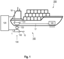
- the air supply apparatus 100 includes a first turbocharger 130 having a first compressor 131 and a first turbine 132.
- the first turbine 132 is drivable by exhaust gas provided from one or more engines 120.
- “drivable by exhaust gas” can be understood in that exhaust gas is provided for driving.
- the first turbine 132 may be connected to the one or more engines 120, e.g. by one or more pipes, such that the one or more engines 120 can supply exhaust gas to the first turbine 132.
- the one or more engines 120 may be turbocharged.
- the exhaust gas supplied from the one or more engines 120 to the first turbine 132 can already be expanded in one or more turbochargers of the one or more engines 120.
- the first compressor 131 is coupled to the first turbine 132 via a transmission 133 configured for changing a speed of the first compressor 131.
- the transmission 133 can be configured for varying a speed of the first compressor 131.
- the transmission 133 can be configured for increasing the speed of the first compressor 131 compared to the speed of the first turbine 132.
- the transmission 133 can be configured for decreasing the speed of the first compressor 131 compared to the speed of the first turbine 132.
- the air supply apparatus 100 includes an air lubrication device 140 for resistance reduction of the ship.
- the first compressor 131 is connected with the air lubrication device 140, particularly via a second air supply pipe 17, for supplying air to the air lubrication device 140.
- a first turbocharger with a transmission as described herein has the advantage that the speed of the first compressor used for supplying air to the air lubrication device can be varied, and thus the amount of air supplied to the air lubrication device can be adjusted.
- the transmission to increase the speed of the first compressor
- the amount of air supplied to the air lubrication device can be increased.
- the amount of air supplied to the air lubrication device can be decreased.
- the amount of air supplied to the air lubrication device can be controlled on demand.
- the efficiency of the first compressor for supplying air to the air lubrication device can be increased. Consequently, the effectivity of the air lubrication device can be improved, resulting in an increased bubble generation under the vessel's hull and thus a higher reduction of water-hull friction of the ship. As result thereof, the overall reduction of energy usage of the ship can be reduced such that savings of fuel can be achieved resulting in a reduction of the overall operation costs.
- the transmission 133 can be a mechanical transmission, an electrical transmission, a pneumatic transmission or a hydraulic transmission. According to an example, which can be combined with other embodiments described herein, the transmission 133 includes a generator and an electric motor.
- a transmission as described herein e.g. the first transmission 133 and/or the second transmission 136 described in the following, can be configured to be variable.
- the first transmission 133 and/or the second transmission 136 can have a variable transmission ratio.
- a transmission as described herein may be configured for providing a changeable transmission ratio.
- the speed of the first compressor 131 and/or the second compressor 135 can beneficially be adjusted and controlled during operation of the ship, i.e. during operation of the one or more engines 120, particularly independently from the speed of the connected turbine, e.g. the first turbine 132 and/or the second turbine 134, as described herein.
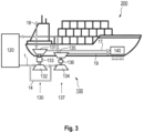
- the air supply apparatus further includes a second turbocharger 137 having a second compressor 135 and a second turbine 134.
- the second turbine 134 is drivable by exhaust gas provided from the one or more engines 120. Accordingly, the second turbine 134 may be connected to the one or more engines 120, e.g. by one or more pipes, such that the one or more engines 120 can supply exhaust gas to the second turbine 134. Additionally or alternatively, the second turbine 134 can be drivable by exhaust gas provided from the first turbine 132. Accordingly, the second turbine 134 may be connected to the first turbine 132, e.g.
- the second compressor 135 is connected with the air lubrication device 140, particularly via a third air supply pipe 19, for supplying air to the air lubrication device 140.
- the second turbine 134 may be drivable by compressed air supplied from the first air supply pipe 16, as exemplarily shown in Figs. 5 to 8 , to the second turbine 134. Accordingly, it is to be understood that an air supply pipe (not explicitly shown in the figures) from the third compressor 111 to the second turbine 134 may be provided.
- the first turbine 132 may be drivable by compressed air supplied from the first air supply pipe 16 (shown in Figs. 5 to 8 ) to the first turbine 2 Accordingly, it is to be understood that an air supply pipe (not explicitly shown in the figures) from the third compressor 111 to the first turbine 132 may be provided.
- the second compressor 135 is coupled to the second turbine 134 via a further transmission 136.
- the further transmission 136 is configured for changing a speed of the second compressor 135.
- the further transmission 136 can be configured for varying a speed of the second compressor 135.
- the further transmission 136 can be configured for increasing the speed of the second compressor 135 compared to the speed of the second turbine 134.
- the further transmission 136 can be configured for decreasing the speed of the second compressor 135 compared to the speed of the second turbine 134.
- the further transmission 136 can be a mechanical transmission, an electrical transmission, a pneumatic transmission or a hydraulic transmission. According to an example, which can be combined with other embodiments described herein, the further transmission 136 includes a generator and an electric motor.
- the air supply apparatus further includes a third turbocharger 110 having a third compressor 111 and a third turbine 112.
- the third turbocharger 110 can be a turbocharger or several turbochargers for charging the one or more engines 120.
- the third turbocharger 110 shown in the figures may represent one or more turbochargers.
- the one or more engines 120 may be charged or not (i.e. uncharged).
- the third turbine 112 is connected with an exhaust gas receiver 122 of the one or more engines 120 via a first exhaust gas pipe 11.
- the turbocharger of the air supply apparatus is a separate turbocharger not employed for charging the engine.
- the first turbocharger 130 is a secondary turbine-compressor pair provided in addition to a turbocharger for charging the engine.
- no mechanical force is taken from an engine's turbocharger main turbine (e.g. the third turbine 112) to the air supply apparatus.
- the first exhaust gas pipe 11 can be connected to a flow controller 160 for controlling an exhaust gas flow provided from the exhaust gas receiver 122 to the third turbine 112, as exemplarily shown in Fig. 8 .
- the flow controller 160 may be provided in a first bypass piping 13 bypassing the third turbine 112.
- the first turbine 132 can be connected with the third turbine 112 via a second exhaust gas pipe 12.
- the second exhaust gas pipe 12 can be connected to a bypass valve 170 for controlling an exhaust gas flow provided from the third turbine 112 to the first turbine 132.
- the bypass valve 170 may be provided in a second bypass piping 14 bypassing the first turbine 132.
- the third compressor can be connected with an air receiver 121 of the one or more engines 120 via a first air supply pipe 16.
- the first air supply pipe 16 includes a charge air cooler 150.
- a further flow controller 161 may be provided downstream of the first turbine 132 of the first turbocharger.
- the piping in which the further flow controller 161 is provided can be connected via an exhaust gas connection 20 to the exhaust gas outlet piping 15.
- the exhaust gas outlet piping 15 may be part of an exhaust system.
- the exhaust system can include an exhaust gas aftertreatment apparatus and/or a silencer before the exhaust gas is released to the environment.
- an exhaust gas aftertreatment apparatus and/or a silencer may also be provided in the other embodiments described herein.
- a ship 200 including an air supply apparatus according to any embodiments described herein is provided.
- a ship with a more energy efficient system for water-hull friction reduction can be provided, such that the overall operation costs can be reduced.
- the method 300 includes driving (represented by block 310 in Fig. 9a ) a first turbocharger 130 by using exhaust gas from one or more engines 120. Additionally, the method includes changing (represented by block 320 in Fig. 9a ) a speed of a first compressor 131 of the first turbocharger 130 by using a transmission 133 coupled to a first turbine 132 and to the first compressor 131 of the first turbocharger 130. Further, the method includes supplying (represented by block 330 in Fig. 9a ) air from the first compressor 131 of the first turbocharger 130 to the air lubrication device 140.
- changing (represented by block 320 in Figs. 9a, 9b and 9c ) the speed of a first compressor 131 may include varying the speed of the first compressor 131.
- changing the speed of the first compressor 131 by using the transmission 133 can include increasing the speed of the first compressor 131 compared to the speed of the first turbine 132.
- the changing the speed of the first compressor 131 by using the transmission 133 can include decreasing the speed of the first compressor 131 compared to the speed of the first turbine 132.
- changing (represented by block 320 in Fig. 9b ) the speed of the first compressor 131 comprises using (represented by block 321 in Fig. 9b ) a second turbine 134 in parallel to the first turbine 132.
- the first turbine 132 and the second turbine 134 are coupled to the first compressor 131 via the transmission 133.
- the method 300 further includes controlling (represented by block 335 in Fig. 9b ) an amount of air provided to the air lubrication device 140 by controlling a rotational speed of the first turbocharger 130.
- the rotational speed of the first turbocharger 130 can be controlled by controlling an exhaust gas flow provided to a third turbine 112 of a third turbocharger 110 being connected with an exhaust gas receiver 122 of the one or more engines 120.
- the exhaust gas flow provided to the third turbine 112 of the third turbocharger 110 can be controlled by using (represented by block 336 in Fig. 9b ) a flow controller 160, as exemplarily shown in Figs. 7 and 8 .
- controlling (represented by block 335 in Fig. 9b ) the amount of air provided to the air lubrication device 140 can include controlling a rotational speed of the first turbocharger 130 by controlling an exhaust gas flow provided to the first turbine 132 by using (represented by block 337 in Fig. 9b ) a bypass valve 170, as exemplarily shown in Figs. 7 and 8 .
- the bypass valve 170 can be provided in a second bypass piping 14 bypassing the first turbine 132.
- an amount of air provided to the air lubrication device 140 can include controlling a rotational speed of the first turbocharger 130 by using (represented by block 338 in Fig. 9b ) a further flow controller 161 provided downstream of the first turbine 132 of the first turbocharger, as exemplarily described with reference to Fig. 8 .
- the method 300 further includes driving (represented by block 340 in Fig. 9c ) a second turbocharger 137 by using exhaust gas from the one or more engines. Additionally or alternatively, driving (represented by block 340 in Fig. 9c ) the second turbocharger 137 can be conducted by using exhaust from the first turbine 132.
- the second turbocharger 137 has a second compressor 135 coupled to a second turbine 134 via a further transmission 136.
- the further transmission 136 is configured for changing a speed of the second compressor 135.
- the method 300 as exemplarily illustrated in Fig. 9c includes changing (represented by block 350 in Fig.
- the method 300 includes supplying (represented by block 360 in Fig. 9c ) air from the second compressor 135 of the second turbocharger 137 to the air lubrication device 140.
- embodiments described herein beneficially provide for an improved air lubrication device for which the amount of air supplied to the air lubrication device can be controlled and adjusted.
- the effectivity of the air lubrication device can be improved by employing a transmission for increasing the speed of a compressor used for supplying air to the air lubrication device. Accordingly, an increased bubble generation under the vessel's hull and thus a higher reduction of water-hull friction of the ship can be achieved, resulting in a reduction of the overall operation costs.
Landscapes
- Engineering & Computer Science (AREA)
- Chemical & Material Sciences (AREA)
- Combustion & Propulsion (AREA)
- Mechanical Engineering (AREA)
- General Engineering & Computer Science (AREA)
- Physics & Mathematics (AREA)
- Fluid Mechanics (AREA)
- Ocean & Marine Engineering (AREA)
- Supercharger (AREA)
Claims (15)
- Luftzufuhrvorrichtung (100) für ein Schiff (200), umfassend:- einen ersten Turbolader (130) mit einem ersten Verdichter (131) und einer ersten Turbine (132), die mittels von einem oder mehreren Motoren (120) vorgesehenen Abgasen antreibbar ist, wobei der erste Verdichter (131) über ein Getriebe (133) mit der ersten Turbine (132) gekoppelt ist, das dazu ausgelegt ist, die Drehzahl des ersten Verdichters (131) in Bezug zur ersten Turbine (132) zu verändern, wobei der erste Turbolader (130) ein sekundäres Turbinen-Verdichter-Paar ist, das zusätzlich zu einem Turbolader zum Aufladen des einen oder der mehreren Motoren (120) vorgesehen ist; und- eine Luftschmiervorrichtung (140) zur Widerstandsverringerung des Schiffs, wobei der erste Verdichter (131) mit der Luftschmiervorrichtung (140) verbunden ist, um der Luftschmiervorrichtung (140) Luft zuzuführen.
- Luftzufuhrvorrichtung (100) nach Anspruch 1, wobei das Getriebe (133) mechanisch, elektrisch, pneumatisch oder hydraulisch ist.
- Luftzufuhrvorrichtung (100) nach Anspruch 1 oder 2, ferner umfassend eine zweite Turbine (134) parallel zur ersten Turbine (132), wobei die erste Turbine (132) und die zweite Turbine (134) über das Getriebe (133) mit dem ersten Verdichter (131) gekoppelt sind.
- Luftzufuhrvorrichtung (100) nach einem der Ansprüche 1 bis 3, wobei das Getriebe (133) einen Generator und einen Elektromotor umfasst.
- Luftzufuhrvorrichtung (100) nach Anspruch 1 oder 2, ferner umfassend einen zweiten Turbolader (137) mit einem zweiten Verdichter (135) und einer zweiten Turbine (134), wobei die zweite Turbine (134) mittels von dem einem oder den mehreren Motoren (120) vorgesehenen Abgasen und/oder mittels von der ersten Turbine (132) vorgesehenen Abgasen angetrieben wird, wobei der zweite Verdichter (135) über ein weiteres Getriebe (136) mit der zweiten Turbine (134) gekoppelt ist, das dazu ausgelegt ist, die Drehzahl des zweiten Verdichters (135) zu verändern.
- Luftzufuhrvorrichtung (100) nach Anspruch 5, wobei das weitere Getriebe (136) mechanisch, elektrisch, pneumatisch oder hydraulisch ist.
- Luftzufuhrvorrichtung (100) nach einem der Ansprüche 1 bis 6, wobei der Turbolader zum Aufladen des einen oder der mehreren Motoren (120) ein dritter Turbolader (110) mit einem dritten Verdichter (111) und einer dritten Turbine (112) ist, die mit einem Abgassammelgefäß (122) des einen oder der mehreren Motoren (120) über ein erstes Abgasrohr (11) verbunden ist, wobei das erste Abgasrohr (11) mit einem Durchflussregler (160) verbunden ist, um einen vom Abgassammelgefäß (122) zur dritten Turbine (112) zugeführten Abgasfluss zu regeln, insbesondere wobei der Durchflussregler (160) in einer ersten Bypassleitung (13) vorgesehen, welche die dritte Turbine (112) umgeht.
- Luftzufuhrvorrichtung (100) nach Anspruch 7, wobei die erste Turbine (132) über eine zweite Abgasleitung (12) mit der dritten Turbine (112) verbunden ist, wobei die zweite Abgasleitung (12) mit einem Bypassventil (170) verbunden ist, um einen von der dritten Turbine (112) zur ersten Turbine (132) zugeführten Abgasfluss zu regeln, insbesondere wobei das Bypassventil (170) in einer zweiten Bypassleitung (14) vorgesehen ist, welche die erste Turbine (132) umgeht.
- Luftzufuhrvorrichtung (100) nach einem der Ansprüche 7 oder 8, wobei der dritte Verdichter (111) über eine erste Luftzufuhrleitung (16) mit einem Luftsammelbehälter (121) des einen oder der mehreren Motoren (120) verbunden ist, insbesondere wobei die erste Luftzufuhrleitung (16) einen Ladeluftkühler (150) umfasst.
- Schiff (200), umfassend eine Luftzufuhrvorrichtung (100) nach einem der Ansprüche 1 bis 9.
- Verfahren (300) zum Zuführen von Luft zu einer Luftschmiervorrichtung (140) eines Schiffs, Folgendes umfassend:- Antreiben (310) eines ersten Turboladers (130) durch die Verwendung von Abgas von einem oder mehreren Motoren (120);- Verändern (320) der Drehzahl eines ersten Verdichters (131) in Bezug zu einer ersten Turbine (132) des ersten Turboladers (130) durch die Verwendung eines Getriebes (133), das mit der ersten Turbine (132) und mit dem ersten Verdichter (131) des ersten Turboladers (130) gekoppelt ist, wobei der erste Turbolader (130) ein sekundäres Turbinen-Verdichter-Paar ist, das zusätzlich zu einem Turbolader zum Aufladen des einen oder der mehreren Motoren (120) vorgesehen ist; und- Zuführen (330) von Luft vom ersten Verdichter (131) des ersten Turboladers (130) zur Luftschmiervorrichtung (140).
- Verfahren (300) nach Anspruch 11, wobei das Verändern (320) der Drehzahl des ersten Verdichters (131) das Verwenden (321) einer zweiten Turbine (134) parallel zur ersten Turbine (132) umfasst, wobei die erste Turbine (132) und die zweite Turbine (134) über das Getriebe (133) mit dem ersten Verdichter (131) gekoppelt sind.
- Verfahren (300) nach Anspruch 11, ferner Folgendes umfassend:- Antreiben (340) eines zweiten Turboladers (137) durch die Verwendung von Abgas von dem einem oder den mehreren Motoren und/oder durch die Verwendung von Abgas von der ersten Turbine (132), wobei der zweite Turbolader (137) einen zweiten Verdichter (135) aufweist, der über ein weiteres Getriebe (136) mit der zweiten Turbine (134) gekoppelt ist, das dazu ausgelegt ist, die Drehzahl des zweiten Verdichters (135) zu verändern,- Verändern (350) der Drehzahl des zweiten Verdichters (135) durch die Verwendung des weiteren Getriebes (136) und- Zuführen (360) von Luft vom zweiten Verdichter (135) des zweiten Turboladers (137) zur Luftschmiervorrichtung (140) .
- Verfahren (300) nach einem der Ansprüche 11 bis 13, ferner umfassend Steuern (335) der Menge an Luft, die der Luftschmiervorrichtung (140) zugeführt wird, durch Steuern der Drehzahl des ersten Turboladers (130) durch Steuern eines Abgasflusses zu einer dritten Turbine (112) eines dritten Turboladers (110), welcher der Turbolader zum Aufladen des einen oder der mehreren Motoren (120) und mit einem Abgassammelgefäß (122) des einen oder der mehreren Motoren (120) verbunden ist, durch Verwenden (336) eines Durchflussreglers (160), insbesondere wobei der Durchflussregler (160) in einer ersten Bypassleitung (13) vorgesehen ist, welche die dritte Turbine (112) umgeht.
- Verfahren (300) nach einem der Ansprüche 11 bis 14, ferner umfassend Steuern (335) der Menge an Luft, die der Luftschmiervorrichtung (140) zugeführt wird, durch Steuern der Drehzahl des ersten Turboladers (130) durch Steuern des Abgasstroms zur ersten Turbine (132) durch Verwenden (337) eines Bypassventils (170), wobei das Bypassventil (170) in einer zweiten Bypassleitung (14) vorgesehen ist, welche die erste Turbine (132) umgeht.
Applications Claiming Priority (2)
| Application Number | Priority Date | Filing Date | Title |
|---|---|---|---|
| EP20169438.7A EP3895973A1 (de) | 2020-04-14 | 2020-04-14 | Luftzufuhrvorrichtung für ein schiff, schiff damit und verfahren zum zuführen von luft zu einer luftschmiervorrichtung |
| PCT/EP2021/059507 WO2021209422A1 (en) | 2020-04-14 | 2021-04-13 | Air supply apparatus for a ship, ship including the same, and method for supplying air to an air lubrication device |
Publications (2)
| Publication Number | Publication Date |
|---|---|
| EP4136018A1 EP4136018A1 (de) | 2023-02-22 |
| EP4136018B1 true EP4136018B1 (de) | 2025-02-26 |
Family
ID=70289577
Family Applications (2)
| Application Number | Title | Priority Date | Filing Date |
|---|---|---|---|
| EP20169438.7A Withdrawn EP3895973A1 (de) | 2020-04-14 | 2020-04-14 | Luftzufuhrvorrichtung für ein schiff, schiff damit und verfahren zum zuführen von luft zu einer luftschmiervorrichtung |
| EP21716787.3A Active EP4136018B1 (de) | 2020-04-14 | 2021-04-13 | Luftzufuhrvorrichtung für ein schiff, schiff damit und verfahren zum zuführen von luft zu einer luftschmiervorrichtung |
Family Applications Before (1)
| Application Number | Title | Priority Date | Filing Date |
|---|---|---|---|
| EP20169438.7A Withdrawn EP3895973A1 (de) | 2020-04-14 | 2020-04-14 | Luftzufuhrvorrichtung für ein schiff, schiff damit und verfahren zum zuführen von luft zu einer luftschmiervorrichtung |
Country Status (6)
| Country | Link |
|---|---|
| US (1) | US12263913B2 (de) |
| EP (2) | EP3895973A1 (de) |
| JP (1) | JP7642674B2 (de) |
| KR (1) | KR20230002683A (de) |
| FI (1) | FI4136018T3 (de) |
| WO (1) | WO2021209422A1 (de) |
Families Citing this family (5)
| Publication number | Priority date | Publication date | Assignee | Title |
|---|---|---|---|---|
| KR20230097040A (ko) * | 2020-10-01 | 2023-06-30 | 메르스크 에이/에스 | 선박의 선체를 위한 공기 공급 시스템, 및 공기 공급 시스템을 포함하는 선박 |
| USD1091803S1 (en) * | 2021-12-27 | 2025-09-02 | Parker Maritime Technologies, LLC | Compressor-free air lubrication system |
| CN114954869B (zh) * | 2022-05-21 | 2023-11-21 | 西北工业大学 | 一种集热管理与减阻双重功能于一体的水下航行器电池舱 |
| WO2025093440A1 (en) * | 2023-11-03 | 2025-05-08 | Accelleron Switzerland Ltd. | Air supply apparatus, ship including the same, and method of supplying air to an air-powered device |
| DE102024103627B3 (de) * | 2024-02-09 | 2025-08-14 | Man Energy Solutions Se | Schiffsantriebssystem und Verfahren zum Betreiben desselben |
Family Cites Families (14)
| Publication number | Priority date | Publication date | Assignee | Title |
|---|---|---|---|---|
| JP2640757B2 (ja) * | 1988-07-18 | 1997-08-13 | 株式会社いすゞセラミックス研究所 | 過給機の制御装置 |
| US6324846B1 (en) * | 1999-03-31 | 2001-12-04 | Caterpillar Inc. | Exhaust gas recirculation system for an internal combustion engine |
| JP2012097606A (ja) * | 2010-10-29 | 2012-05-24 | Isuzu Motors Ltd | ターボ過給システム |
| JP5294135B1 (ja) * | 2012-03-22 | 2013-09-18 | 西芝電機株式会社 | 船舶の圧縮空気供給システムとその装置 |
| JP5805044B2 (ja) * | 2012-10-12 | 2015-11-04 | 三菱重工業株式会社 | 船体抵抗低減システムおよび船体の抵抗低減方法 |
| JP6357016B2 (ja) * | 2014-05-26 | 2018-07-11 | ボルボトラックコーポレーション | エンジンの過給装置 |
| KR20140083944A (ko) * | 2014-05-28 | 2014-07-04 | 삼성중공업 주식회사 | 선박의 공기윤활시스템 |
| JP6647630B2 (ja) * | 2014-07-11 | 2020-02-14 | 国立研究開発法人 海上・港湾・航空技術研究所 | 空気潤滑式船舶の空気供給システム |
| AT517668A1 (de) * | 2015-09-04 | 2017-03-15 | Ge Jenbacher Gmbh & Co Og | Brennkraftmaschine |
| DE102016203823B3 (de) * | 2016-03-09 | 2017-08-24 | Ford Global Technologies, Llc | Verfahren zum Betreiben einer abgasturboaufgeladenen Brennkraftmaschine mit Teilabschaltung |
| BR102017014513B1 (pt) * | 2017-07-05 | 2020-04-22 | Duo Engenharia Criativa Ltda Epp | disposição construtiva em turbocompressor de baixa temperatura para motor de combustão interna |
| DE102019119260A1 (de) * | 2019-07-16 | 2021-01-21 | Bayerische Motoren Werke Aktiengesellschaft | Konditioniervorrichtung für ein Kraftfahrzeug, Kraftfahrzeug mit einer Konditioniervorrichtung und Verfahren zum Betreiben einer Konditioniervorrichtung in einem Kraftfahrzeug |
| JP2021148078A (ja) * | 2020-03-19 | 2021-09-27 | 本田技研工業株式会社 | 過給機、及び、過給機の制御方法 |
| JP7512319B2 (ja) * | 2021-04-06 | 2024-07-08 | エムエーエヌ・エナジー・ソリューションズ・フィリアル・アフ・エムエーエヌ・エナジー・ソリューションズ・エスイー・ティスクランド | 機械的エネルギー及び加圧ガスを届けるための大型ターボ過給式2ストローク内燃機関及び方法 |
-
2020
- 2020-04-14 EP EP20169438.7A patent/EP3895973A1/de not_active Withdrawn
-
2021
- 2021-04-13 US US17/918,486 patent/US12263913B2/en active Active
- 2021-04-13 FI FIEP21716787.3T patent/FI4136018T3/fi active
- 2021-04-13 EP EP21716787.3A patent/EP4136018B1/de active Active
- 2021-04-13 KR KR1020227039581A patent/KR20230002683A/ko active Pending
- 2021-04-13 JP JP2022562459A patent/JP7642674B2/ja active Active
- 2021-04-13 WO PCT/EP2021/059507 patent/WO2021209422A1/en not_active Ceased
Also Published As
| Publication number | Publication date |
|---|---|
| CN115515848A (zh) | 2022-12-23 |
| EP3895973A1 (de) | 2021-10-20 |
| FI4136018T3 (fi) | 2025-05-16 |
| US20230143335A1 (en) | 2023-05-11 |
| JP2023522641A (ja) | 2023-05-31 |
| JP7642674B2 (ja) | 2025-03-10 |
| EP4136018A1 (de) | 2023-02-22 |
| WO2021209422A1 (en) | 2021-10-21 |
| US12263913B2 (en) | 2025-04-01 |
| KR20230002683A (ko) | 2023-01-05 |
Similar Documents
| Publication | Publication Date | Title |
|---|---|---|
| EP4136018B1 (de) | Luftzufuhrvorrichtung für ein schiff, schiff damit und verfahren zum zuführen von luft zu einer luftschmiervorrichtung | |
| JP7428722B2 (ja) | 船舶用の空気供給装置、空気供給装置を含む船舶および空気潤滑装置に空気を供給するための方法 | |
| RU2600839C2 (ru) | Гибридная турбокомпаундная двигательная установка с наддувом | |
| CN101896706B (zh) | 增压装置 | |
| JPS62205896A (ja) | 舶用過給式デイ−ゼル機関 | |
| EP2729684A1 (de) | Hybridsystem mit aufladesystem und verfahren zu seinem betrieb | |
| WO2014058008A1 (ja) | 船体抵抗低減システムおよび船体の抵抗低減方法 | |
| CN101898548A (zh) | 船驱动系统以及装备着该船驱动系统的船 | |
| JP6364691B2 (ja) | 内燃機関の過給機余剰動力回収装置 | |
| JP2006242051A (ja) | エンジンの余剰排気エネルギ回収システム | |
| JP2008111384A (ja) | 船舶用エンジンの余剰排気エネルギ回収システム | |
| CN115515848B (en) | Air supply device for a ship, a ship comprising such an air supply device and a method of supplying air to an air lubrication device | |
| JP5886188B2 (ja) | 内燃機関の過給機余剰動力回収装置 | |
| EP3263864B1 (de) | Motorstartvorrichtung, startverfahren und mit der startvorrichtung ausgestattetes schiff | |
| US12600453B2 (en) | Air supply apparatus for a ship, ship including the same, and method of supplying air to an air lubrication device | |
| WO2025093440A1 (en) | Air supply apparatus, ship including the same, and method of supplying air to an air-powered device | |
| EP4046901A1 (de) | Luftzuführvorrichtung für ein schiff, schiff damit und verfahren zum installieren einer brennstoffzelle in einer luftzuführvorrichtung | |
| KR20230150405A (ko) | 선박용 공기 공급 장치, 이를 포함하는 선박, 및 공기 윤활 디바이스에 공기를 공급하는 방법 | |
| WO2006128974A1 (en) | Method and arrangement for improving load acceptance of piston engine | |
| CN117446076A (zh) | 供气装置、包括其的船舶和向空气润滑设备供气的方法 | |
| JP2003049674A (ja) | 内燃機関用過給システム | |
| JP2000204957A (ja) | 過給機付き内燃機関 |
Legal Events
| Date | Code | Title | Description |
|---|---|---|---|
| STAA | Information on the status of an ep patent application or granted ep patent |
Free format text: STATUS: UNKNOWN |
|
| STAA | Information on the status of an ep patent application or granted ep patent |
Free format text: STATUS: THE INTERNATIONAL PUBLICATION HAS BEEN MADE |
|
| PUAI | Public reference made under article 153(3) epc to a published international application that has entered the european phase |
Free format text: ORIGINAL CODE: 0009012 |
|
| STAA | Information on the status of an ep patent application or granted ep patent |
Free format text: STATUS: REQUEST FOR EXAMINATION WAS MADE |
|
| 17P | Request for examination filed |
Effective date: 20221019 |
|
| AK | Designated contracting states |
Kind code of ref document: A1 Designated state(s): AL AT BE BG CH CY CZ DE DK EE ES FI FR GB GR HR HU IE IS IT LI LT LU LV MC MK MT NL NO PL PT RO RS SE SI SK SM TR |
|
| DAV | Request for validation of the european patent (deleted) | ||
| DAX | Request for extension of the european patent (deleted) | ||
| GRAP | Despatch of communication of intention to grant a patent |
Free format text: ORIGINAL CODE: EPIDOSNIGR1 |
|
| STAA | Information on the status of an ep patent application or granted ep patent |
Free format text: STATUS: GRANT OF PATENT IS INTENDED |
|
| INTG | Intention to grant announced |
Effective date: 20241023 |
|
| RAP3 | Party data changed (applicant data changed or rights of an application transferred) |
Owner name: ACCELLERON SWITZERLAND LTD. |
|
| GRAS | Grant fee paid |
Free format text: ORIGINAL CODE: EPIDOSNIGR3 |
|
| GRAA | (expected) grant |
Free format text: ORIGINAL CODE: 0009210 |
|
| STAA | Information on the status of an ep patent application or granted ep patent |
Free format text: STATUS: THE PATENT HAS BEEN GRANTED |
|
| AK | Designated contracting states |
Kind code of ref document: B1 Designated state(s): AL AT BE BG CH CY CZ DE DK EE ES FI FR GB GR HR HU IE IS IT LI LT LU LV MC MK MT NL NO PL PT RO RS SE SI SK SM TR |
|
| REG | Reference to a national code |
Ref country code: GB Ref legal event code: FG4D |
|
| RIN1 | Information on inventor provided before grant (corrected) |
Inventor name: TISSOT, JEAN-FRANCOIS Inventor name: KEINAENEN, JARI |
|
| REG | Reference to a national code |
Ref country code: CH Ref legal event code: EP |
|
| REG | Reference to a national code |
Ref country code: DE Ref legal event code: R096 Ref document number: 602021026763 Country of ref document: DE |
|
| REG | Reference to a national code |
Ref country code: IE Ref legal event code: FG4D |
|
| REG | Reference to a national code |
Ref country code: FI Ref legal event code: FGE |
|
| REG | Reference to a national code |
Ref country code: NL Ref legal event code: MP Effective date: 20250226 |
|
| PG25 | Lapsed in a contracting state [announced via postgrant information from national office to epo] |
Ref country code: RS Free format text: LAPSE BECAUSE OF FAILURE TO SUBMIT A TRANSLATION OF THE DESCRIPTION OR TO PAY THE FEE WITHIN THE PRESCRIBED TIME-LIMIT Effective date: 20250526 |
|
| PGFP | Annual fee paid to national office [announced via postgrant information from national office to epo] |
Ref country code: FI Payment date: 20250424 Year of fee payment: 5 |
|
| PG25 | Lapsed in a contracting state [announced via postgrant information from national office to epo] |
Ref country code: PL Free format text: LAPSE BECAUSE OF FAILURE TO SUBMIT A TRANSLATION OF THE DESCRIPTION OR TO PAY THE FEE WITHIN THE PRESCRIBED TIME-LIMIT Effective date: 20250226 |
|
| PGFP | Annual fee paid to national office [announced via postgrant information from national office to epo] |
Ref country code: DE Payment date: 20250422 Year of fee payment: 5 |
|
| PG25 | Lapsed in a contracting state [announced via postgrant information from national office to epo] |
Ref country code: ES Free format text: LAPSE BECAUSE OF FAILURE TO SUBMIT A TRANSLATION OF THE DESCRIPTION OR TO PAY THE FEE WITHIN THE PRESCRIBED TIME-LIMIT Effective date: 20250226 |
|
| PGFP | Annual fee paid to national office [announced via postgrant information from national office to epo] |
Ref country code: GB Payment date: 20250423 Year of fee payment: 5 |
|
| REG | Reference to a national code |
Ref country code: LT Ref legal event code: MG9D |
|
| PG25 | Lapsed in a contracting state [announced via postgrant information from national office to epo] |
Ref country code: IS Free format text: LAPSE BECAUSE OF FAILURE TO SUBMIT A TRANSLATION OF THE DESCRIPTION OR TO PAY THE FEE WITHIN THE PRESCRIBED TIME-LIMIT Effective date: 20250626 |
|
| PGFP | Annual fee paid to national office [announced via postgrant information from national office to epo] |
Ref country code: NO Payment date: 20250424 Year of fee payment: 5 |
|
| PG25 | Lapsed in a contracting state [announced via postgrant information from national office to epo] |
Ref country code: NL Free format text: LAPSE BECAUSE OF FAILURE TO SUBMIT A TRANSLATION OF THE DESCRIPTION OR TO PAY THE FEE WITHIN THE PRESCRIBED TIME-LIMIT Effective date: 20250226 |
|
| PGFP | Annual fee paid to national office [announced via postgrant information from national office to epo] |
Ref country code: IT Payment date: 20250530 Year of fee payment: 5 |
|
| PG25 | Lapsed in a contracting state [announced via postgrant information from national office to epo] |
Ref country code: HR Free format text: LAPSE BECAUSE OF FAILURE TO SUBMIT A TRANSLATION OF THE DESCRIPTION OR TO PAY THE FEE WITHIN THE PRESCRIBED TIME-LIMIT Effective date: 20250226 |
|
| PG25 | Lapsed in a contracting state [announced via postgrant information from national office to epo] |
Ref country code: PT Free format text: LAPSE BECAUSE OF FAILURE TO SUBMIT A TRANSLATION OF THE DESCRIPTION OR TO PAY THE FEE WITHIN THE PRESCRIBED TIME-LIMIT Effective date: 20250626 Ref country code: LV Free format text: LAPSE BECAUSE OF FAILURE TO SUBMIT A TRANSLATION OF THE DESCRIPTION OR TO PAY THE FEE WITHIN THE PRESCRIBED TIME-LIMIT Effective date: 20250226 |
|
| PGFP | Annual fee paid to national office [announced via postgrant information from national office to epo] |
Ref country code: FR Payment date: 20250425 Year of fee payment: 5 |
|
| PG25 | Lapsed in a contracting state [announced via postgrant information from national office to epo] |
Ref country code: BG Free format text: LAPSE BECAUSE OF FAILURE TO SUBMIT A TRANSLATION OF THE DESCRIPTION OR TO PAY THE FEE WITHIN THE PRESCRIBED TIME-LIMIT Effective date: 20250226 Ref country code: GR Free format text: LAPSE BECAUSE OF FAILURE TO SUBMIT A TRANSLATION OF THE DESCRIPTION OR TO PAY THE FEE WITHIN THE PRESCRIBED TIME-LIMIT Effective date: 20250527 |
|
| PGFP | Annual fee paid to national office [announced via postgrant information from national office to epo] |
Ref country code: RO Payment date: 20250521 Year of fee payment: 5 |
|
| REG | Reference to a national code |
Ref country code: AT Ref legal event code: MK05 Ref document number: 1770414 Country of ref document: AT Kind code of ref document: T Effective date: 20250226 |
|
| PG25 | Lapsed in a contracting state [announced via postgrant information from national office to epo] |
Ref country code: SE Free format text: LAPSE BECAUSE OF FAILURE TO SUBMIT A TRANSLATION OF THE DESCRIPTION OR TO PAY THE FEE WITHIN THE PRESCRIBED TIME-LIMIT Effective date: 20250226 |
|
| PG25 | Lapsed in a contracting state [announced via postgrant information from national office to epo] |
Ref country code: SM Free format text: LAPSE BECAUSE OF FAILURE TO SUBMIT A TRANSLATION OF THE DESCRIPTION OR TO PAY THE FEE WITHIN THE PRESCRIBED TIME-LIMIT Effective date: 20250226 |
|
| PG25 | Lapsed in a contracting state [announced via postgrant information from national office to epo] |
Ref country code: DK Free format text: LAPSE BECAUSE OF FAILURE TO SUBMIT A TRANSLATION OF THE DESCRIPTION OR TO PAY THE FEE WITHIN THE PRESCRIBED TIME-LIMIT Effective date: 20250226 |
|
| PG25 | Lapsed in a contracting state [announced via postgrant information from national office to epo] |
Ref country code: AT Free format text: LAPSE BECAUSE OF FAILURE TO SUBMIT A TRANSLATION OF THE DESCRIPTION OR TO PAY THE FEE WITHIN THE PRESCRIBED TIME-LIMIT Effective date: 20250226 |
|
| PG25 | Lapsed in a contracting state [announced via postgrant information from national office to epo] |
Ref country code: EE Free format text: LAPSE BECAUSE OF FAILURE TO SUBMIT A TRANSLATION OF THE DESCRIPTION OR TO PAY THE FEE WITHIN THE PRESCRIBED TIME-LIMIT Effective date: 20250226 Ref country code: CZ Free format text: LAPSE BECAUSE OF FAILURE TO SUBMIT A TRANSLATION OF THE DESCRIPTION OR TO PAY THE FEE WITHIN THE PRESCRIBED TIME-LIMIT Effective date: 20250226 |
|
| PG25 | Lapsed in a contracting state [announced via postgrant information from national office to epo] |
Ref country code: SK Free format text: LAPSE BECAUSE OF FAILURE TO SUBMIT A TRANSLATION OF THE DESCRIPTION OR TO PAY THE FEE WITHIN THE PRESCRIBED TIME-LIMIT Effective date: 20250226 |
|
| REG | Reference to a national code |
Ref country code: CH Ref legal event code: H13 Free format text: ST27 STATUS EVENT CODE: U-0-0-H10-H13 (AS PROVIDED BY THE NATIONAL OFFICE) Effective date: 20251125 |
|
| REG | Reference to a national code |
Ref country code: DE Ref legal event code: R097 Ref document number: 602021026763 Country of ref document: DE |
|
| PG25 | Lapsed in a contracting state [announced via postgrant information from national office to epo] |
Ref country code: LU Free format text: LAPSE BECAUSE OF NON-PAYMENT OF DUE FEES Effective date: 20250413 |
|
| PG25 | Lapsed in a contracting state [announced via postgrant information from national office to epo] |
Ref country code: MC Free format text: LAPSE BECAUSE OF FAILURE TO SUBMIT A TRANSLATION OF THE DESCRIPTION OR TO PAY THE FEE WITHIN THE PRESCRIBED TIME-LIMIT Effective date: 20250226 |
|
| REG | Reference to a national code |
Ref country code: BE Ref legal event code: MM Effective date: 20250430 |
|
| PLBE | No opposition filed within time limit |
Free format text: ORIGINAL CODE: 0009261 |
|
| STAA | Information on the status of an ep patent application or granted ep patent |
Free format text: STATUS: NO OPPOSITION FILED WITHIN TIME LIMIT |
|
| PG25 | Lapsed in a contracting state [announced via postgrant information from national office to epo] |
Ref country code: BE Free format text: LAPSE BECAUSE OF NON-PAYMENT OF DUE FEES Effective date: 20250430 |
|
| PG25 | Lapsed in a contracting state [announced via postgrant information from national office to epo] |
Ref country code: CH Free format text: LAPSE BECAUSE OF NON-PAYMENT OF DUE FEES Effective date: 20250430 |
|
| 26N | No opposition filed |
Effective date: 20251127 |
|
| PG25 | Lapsed in a contracting state [announced via postgrant information from national office to epo] |
Ref country code: IE Free format text: LAPSE BECAUSE OF NON-PAYMENT OF DUE FEES Effective date: 20250413 |