EP3263864B1 - Motorstartvorrichtung, startverfahren und mit der startvorrichtung ausgestattetes schiff - Google Patents
Motorstartvorrichtung, startverfahren und mit der startvorrichtung ausgestattetes schiff Download PDFInfo
- Publication number
- EP3263864B1 EP3263864B1 EP16755252.0A EP16755252A EP3263864B1 EP 3263864 B1 EP3263864 B1 EP 3263864B1 EP 16755252 A EP16755252 A EP 16755252A EP 3263864 B1 EP3263864 B1 EP 3263864B1
- Authority
- EP
- European Patent Office
- Prior art keywords
- engine
- compressor
- exhaust gas
- electric motor
- starting
- Prior art date
- Legal status (The legal status is an assumption and is not a legal conclusion. Google has not performed a legal analysis and makes no representation as to the accuracy of the status listed.)
- Active
Links
- 238000000034 method Methods 0.000 title claims description 13
- 230000002000 scavenging effect Effects 0.000 claims description 52
- 238000002485 combustion reaction Methods 0.000 description 26
- 239000000779 smoke Substances 0.000 description 12
- 239000007858 starting material Substances 0.000 description 4
- 230000003247 decreasing effect Effects 0.000 description 2
- 230000000994 depressogenic effect Effects 0.000 description 2
- 230000033001 locomotion Effects 0.000 description 2
- 230000002159 abnormal effect Effects 0.000 description 1
- 230000000694 effects Effects 0.000 description 1
- 239000000446 fuel Substances 0.000 description 1
- 238000009434 installation Methods 0.000 description 1
- 238000012986 modification Methods 0.000 description 1
- 230000004048 modification Effects 0.000 description 1
Images

Classifications
-
- F—MECHANICAL ENGINEERING; LIGHTING; HEATING; WEAPONS; BLASTING
- F02—COMBUSTION ENGINES; HOT-GAS OR COMBUSTION-PRODUCT ENGINE PLANTS
- F02B—INTERNAL-COMBUSTION PISTON ENGINES; COMBUSTION ENGINES IN GENERAL
- F02B37/00—Engines characterised by provision of pumps driven at least for part of the time by exhaust
- F02B37/12—Control of the pumps
- F02B37/14—Control of the alternation between or the operation of exhaust drive and other drive of a pump, e.g. dependent on speed
-
- F—MECHANICAL ENGINEERING; LIGHTING; HEATING; WEAPONS; BLASTING
- F02—COMBUSTION ENGINES; HOT-GAS OR COMBUSTION-PRODUCT ENGINE PLANTS
- F02D—CONTROLLING COMBUSTION ENGINES
- F02D41/00—Electrical control of supply of combustible mixture or its constituents
- F02D41/02—Circuit arrangements for generating control signals
- F02D41/04—Introducing corrections for particular operating conditions
- F02D41/06—Introducing corrections for particular operating conditions for engine starting or warming up
- F02D41/062—Introducing corrections for particular operating conditions for engine starting or warming up for starting
-
- F—MECHANICAL ENGINEERING; LIGHTING; HEATING; WEAPONS; BLASTING
- F02—COMBUSTION ENGINES; HOT-GAS OR COMBUSTION-PRODUCT ENGINE PLANTS
- F02B—INTERNAL-COMBUSTION PISTON ENGINES; COMBUSTION ENGINES IN GENERAL
- F02B37/00—Engines characterised by provision of pumps driven at least for part of the time by exhaust
- F02B37/04—Engines with exhaust drive and other drive of pumps, e.g. with exhaust-driven pump and mechanically-driven second pump
- F02B37/11—Engines with exhaust drive and other drive of pumps, e.g. with exhaust-driven pump and mechanically-driven second pump driven by other drive at starting only
-
- F—MECHANICAL ENGINEERING; LIGHTING; HEATING; WEAPONS; BLASTING
- F02—COMBUSTION ENGINES; HOT-GAS OR COMBUSTION-PRODUCT ENGINE PLANTS
- F02B—INTERNAL-COMBUSTION PISTON ENGINES; COMBUSTION ENGINES IN GENERAL
- F02B37/00—Engines characterised by provision of pumps driven at least for part of the time by exhaust
- F02B37/12—Control of the pumps
- F02B37/16—Control of the pumps by bypassing charging air
- F02B37/168—Control of the pumps by bypassing charging air into the exhaust conduit
-
- F—MECHANICAL ENGINEERING; LIGHTING; HEATING; WEAPONS; BLASTING
- F02—COMBUSTION ENGINES; HOT-GAS OR COMBUSTION-PRODUCT ENGINE PLANTS
- F02B—INTERNAL-COMBUSTION PISTON ENGINES; COMBUSTION ENGINES IN GENERAL
- F02B39/00—Component parts, details, or accessories relating to, driven charging or scavenging pumps, not provided for in groups F02B33/00 - F02B37/00
- F02B39/02—Drives of pumps; Varying pump drive gear ratio
- F02B39/08—Non-mechanical drives, e.g. fluid drives having variable gear ratio
- F02B39/10—Non-mechanical drives, e.g. fluid drives having variable gear ratio electric
-
- F—MECHANICAL ENGINEERING; LIGHTING; HEATING; WEAPONS; BLASTING
- F02—COMBUSTION ENGINES; HOT-GAS OR COMBUSTION-PRODUCT ENGINE PLANTS
- F02D—CONTROLLING COMBUSTION ENGINES
- F02D41/00—Electrical control of supply of combustible mixture or its constituents
- F02D41/0002—Controlling intake air
- F02D41/0007—Controlling intake air for control of turbo-charged or super-charged engines
-
- Y—GENERAL TAGGING OF NEW TECHNOLOGICAL DEVELOPMENTS; GENERAL TAGGING OF CROSS-SECTIONAL TECHNOLOGIES SPANNING OVER SEVERAL SECTIONS OF THE IPC; TECHNICAL SUBJECTS COVERED BY FORMER USPC CROSS-REFERENCE ART COLLECTIONS [XRACs] AND DIGESTS
- Y02—TECHNOLOGIES OR APPLICATIONS FOR MITIGATION OR ADAPTATION AGAINST CLIMATE CHANGE
- Y02T—CLIMATE CHANGE MITIGATION TECHNOLOGIES RELATED TO TRANSPORTATION
- Y02T10/00—Road transport of goods or passengers
- Y02T10/10—Internal combustion engine [ICE] based vehicles
- Y02T10/12—Improving ICE efficiencies
Definitions
- the present invention relates to an engine starting equipment adequate for marine large-sized two-cycle diesel engines and the like, a starting method, and a ship equipped with such starting equipment.
- an electric exhaust gas turbocharger (hybrid turbocharger) is put in practical use as a turbocharger provided in marine large-sized two-cycle diesel engines and the like.
- the electric exhaust gas turbocharger is configured such that an electric motor used also as a power generator is directly coupled with a rotor shaft of the turbocharger.
- rotation of the rotor shaft is assisted by making the electric motor activated following after an engine output of an engine body during low load operation of the engine or during increase in engine output in order to prevent temporary air supply shortage of the engine body.
- JP 2004-340122 A discloses a control device for an internal combustion engine having a supercharger with a motor which improves the start-up performance and warm-up performance.
- US 2,585,029 A describes a self-powered turbosupercharger starter system for internal combustion engines with an electric motor which assists rotation of a compressor. By injecting fuel into a chamber connected to a conduit, high-temperature gas is introduced into a turbine to drive it. When the speed of the turbine exceeds the speed of the motor, the motor is uncoupled by a clutch.
- the electric motor increases the rotating speed of the rotor shaft of the turbocharger in advance before start of the engine, so that the compressor in the turbocharger can be driven to generate compressed air.
- the compressed air is sent to a scavenging air receiver so that the pressure in the scavenging air receiver can be boosted.
- the rotation speed of the compressor is quickly increased concurrently with the start of the engine, so that generation of engine smoke caused by temporary shortage in the amount of air can be suppressed.
- the engine can be started without using an electric auxiliary blower (fan) which is conventionally installed on the engine so as to send air to the scavenging air receiver in a range where boosting of the scavenging pressure by the turbocharger is difficult (e.g. from the start of the engine to a low-load range). It is also expected to increase the amount of air supply at the start of the engine to improve a combustion process and to thereby decrease the amount of engine smoke at the engine start.
- fan electric auxiliary blower
- the electric auxiliary blower is conventionally used to boost the pressure of the scavenging air receiver at the start of the engine.
- installation of the electric auxiliary blower complicates the configuration of the engine starter, and power consumption of the electric auxiliary blower needs to be considered.
- the present invention has been made in view of such circumstances, and it is therefore an object of the present invention to provide a starting equipment of an engine, a starting method, and a ship equipped with the starting equipment capable of starting the engine with less power consumption while rotationally driving a compressor with an electric motor and preventing surging of the compressor and also capable of decreasing the amount of engine smoke at the start of the engine.
- a starting equipment of an engine is a starting equipment of an engine equipped with an electric exhaust gas turbocharger having an electric motor configured to assist rotation of a compressor, the starting equipment of an engine including: a bypass passage configured to connect a compressed air outlet of the compressor and an exhaust gas inlet of an exhaust gas turbine; a bypass valve configured to open and close the bypass passage; and a start control unit configured to open the bypass valve and rotate the compressor with the electric motor before start of the engine, to keep the compressor rotating with the electric motor at least at the start of the engine, and to close the bypass valve at a timing corresponding to the start of the engine.
- the start control unit opens the bypass valve and rotates the compressor of the electric exhaust gas turbocharger with the electric motor before start of the engine.
- the air compressed in the compressor flows from the compressed air outlet of the compressor and through the bypass passage into the exhaust gas inlet of the exhaust gas turbine.
- the generated compressed air which is supplied to the exhaust gas turbine through the bypass passage, rotationally drives the exhaust gas turbine and also rotationally drives the compressor coaxial with the exhaust gas turbine. Accordingly, it is possible to drive the compressor with less power, so that the required power of the electric motor can drastically be reduced compared with the case where the bypass passage is not provided.
- the engine is started while the electric motor rotates the compressor.
- a combustion cylinder having a piston at an expansion stroke position is charged with starting compressed air, so that the piston is depressed. As a result, the engine can be started.
- the electric motor rotates the compressor of the electric turbocharger in advance before the start of the engine, the rotation speed of the compressor can quickly be boosted concurrently with the start of the engine. Accordingly, a sufficient amount of air can be provided at the start of the engine.
- the pressure of the scavenging air receiver can be boosted and the two-cycle engine can be started with less power consumption.
- the start control unit closes the bypass valve at the timing corresponding to the start of the engine.
- the compressed air generated in the compressor is no longer supplied to the exhaust gas turbine, so that all the compressed air is sent to the engine (scavenging air receiver), and the engine shifts to normal operation.
- a passage extending from the compressor to the engine is constantly opened. Accordingly, in the two-cycle engine in particular, the pressure of the scavenging air receiver can be boosted higher than the atmospheric pressure to enhance engine starting performance.
- the compressed air of the compressor driven with the electric motor is preferably supplied to the bypass passage and the scavenging air receiver of the engine before the start of the engine.
- the pressure of the compressed air discharged from the compressor is applied to the scavenging air receiver, and the scavenging air receiver is pressurized to the pressure in the compressed air outlet of the compressor. Accordingly, it is possible to boost the pressure of the scavenging air receiver to be higher than the atmospheric pressure to sufficiently secure the amount of air necessary for start of the engine. It also is possible to suppress generation of engine smoke caused by temporary shortage in the air amount.
- the timing of closing the bypass valve is preferably immediately after the start of the two-cycle engine.
- a ship according to the present invention is equipped with any one of the aforementioned starting equipments of an engine.
- the ship can start the engine with less power consumption without causing surging of the compressor, even when the exhaust valves of the engine are closed because the engine is not yet started.
- the pressure of the scavenging air receiver can be boosted at the engine start, the combustion state at the engine start can be enhanced, and the amount of engine smoke can be decreased.
- a starting method of an engine according to the present invention is a starting method of an engine equipped with an electric exhaust gas turbocharger having an electric motor that assists rotation of a compressor, the starting method including: a supercharge preparing step of rotating the compressor of the electric exhaust gas turbocharger with the electric motor and supplying the compressed air discharged from the compressor to an exhaust gas turbine before start of the engine; an engine starting step of starting the engine while rotating the compressor with the electric motor; and a supercharge starting step of supplying the compressed air to the engine at a timing corresponding to the start of the engine.
- the compressor is first rotated with the electric motor, and the compressed air discharged from the compressor is supplied to the exhaust gas turbine in the supercharge preparing step.
- the air compressed in the compressor is supplied to the exhaust gas inlet of the exhaust gas turbine, and the scavenging air receiver is pressurized to the pressure in the compressed air outlet of the compressor.
- the engine is started while the electric motor rotates the compressor in the engine starting step. Since the rotation speed of the compressor is boosted in advance in the supercharge preparing step, the pressure of the scavenging air receiver can quickly be boosted concurrently with the start of the engine in the two-cycle engine. Accordingly, enough combustion air can be supplied from the scavenging air receiver to the engine to allow sufficient start of the engine.
- the pressure of the scavenging air receiver can be boosted to start the two-cycle engine with less power consumption.
- the compressed air generated in the compressor is supplied to the engine side at the timing corresponding to the start of the engine.
- the compressed air is sent to the engine (scavenging air receiver), and the engine shifts to normal operation.
- the starting equipment of an engine, the starting method, and the ship equipped with the starting equipment according to the present invention can start the engine with less power consumption while rotationally driving a compressor with an electric motor and preventing surging of the compressor, and can also decrease the amount of engine smoke at the start of the engine.
- FIG. 1 is a schematic configuration view of a marine large-sized diesel engine 1 and a starting equipment 2 illustrating an embodiment of the present invention.
- the marine large-sized diesel engine 1 (engine) is a uniflow-type two-cycle engine equipped with a plurality of combustion cylinders 4, an exhaust gas manifold 5, and a scavenging air receiver 6.
- a crankshaft 8 is pivotally supported under each of the combustion cylinders 4, with pistons 9 inserted into the combustion cylinders 4 being connected with the crankshaft 8 through connecting rods 10. Reciprocating motions of the pistons 9 in the combustion cylinders 4 are converted into rotary motions of the crankshaft 8, and are used as an output of the marine large-sized diesel engine 1.
- Each of the combustion cylinders 4 has scavenging ports 12 communicating with the inside of the scavenging air receiver 6, the scavenging ports 12 being provided in the vicinity of lower portions of the combustion cylinders 4.
- Each of the combustion cylinders 4 has an exhaust gas port 13 and an exhaust gas valve 14 provided in their upper portions, the exhaust gas port 13 being connected with the exhaust gas manifold 5, the exhaust gas valve 14 being configured to open and close the exhaust gas port 13.
- the exhaust gas valves 14 are constantly biased in a valve closing direction with valve springs 15 (generally air springs), respectively.
- the exhaust gas valves 14 are hydraulically opened.
- the marine large-sized diesel engine 1 is provided with an electric exhaust gas turbocharger 24.
- the electric exhaust gas turbocharger 24 is configured such that an exhaust gas turbine 25 and a compressor 26 rotate in unison through a rotor shaft 27.
- An electric motor 28 provided in one end of the rotor shaft 27 assists rotation of the compressor 26 (rotor shaft 27).
- An exhaust gas gas supply pipe 31 extending from the exhaust gas manifold 5 is connected to an exhaust gas inlet of the exhaust gas turbine 25, and an exhaust gas gas discharge pipe 32 extends from a discharge outlet of the exhaust gas turbine 25.
- a compressed air pipe 35 extending from a compressed air outlet of the compressor 26 is connected to an air cooler 37 attached to the scavenging air receiver 6.
- a bypass passage 44 is disposed to connect the compressed air outlet of the compressor 26 and the exhaust gas inlet of the exhaust gas turbine 25.
- the bypass passage 44 is connected to a bypass valve 45.
- the bypass valve 45 is an on-off valve which opens and closes the bypass passage 44.
- the bypass passage 44 also communicates with the scavenging air receiver 6 through the compressed air pipe 35.
- the bypass passage 44 may be arranged to be branched from the compressed air pipe 35 and to be connected to the exhaust gas inlet of the exhaust gas turbine 25.
- the exhaust gas gas discharged during operation of the marine large-sized diesel engine 1 is supplied to the exhaust gas turbine 25 through the exhaust gas manifold 5 and the exhaust gas gas supply pipe 31, so that the exhaust gas turbine 25 is rotationally driven at high speed.
- the exhaust gas gas after driving the exhaust gas turbine 25 is discharged to the outside through the exhaust gas gas discharge pipe 32.
- the compressor 26 When the exhaust gas turbine 25 rotates, the compressor 26 also rotates, so that the atmospheric air is compressed in the compressor 26.
- the compressed air travels through the compressed air pipe 35 and passes the air cooler 37 before being supplied to the scavenging air receiver 6.
- the compressed air is then supplied to each of the combustion cylinders 4 through the scavenging ports 12. Since intake air is compressed by using the energy of the exhaust gas gas in this way, an air filling rate for filling each of the combustion cylinders 4 with air can be enhanced to achieve enhanced engine efficiency.
- the exhaust gas turbine 25 can rotationally be driven with the energy of exhaust gas gas, so that the compressor 26 can be operated as described before.
- the electric motor 28 assists rotation the compressor 26 to prevent reduction in the air filling rate.
- the starting equipment 2 provided in the marine large-sized diesel engine 1 is configured to include a start control unit 48, a bypass passage 44, and a bypass valve 45.
- the start control unit 48 is a control unit (CPU), which sends operation signals A1 and A2 to the electric motor 28 of the electric exhaust gas turbocharger 24 and the bypass valve 45, respectively.
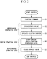
- FIG. 2 is a flowchart illustrating the flow of control in the starter 2.
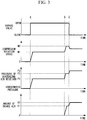
- FIG. 3 is a diagrammatic view illustrating a relationship among opening and closing timing of the bypass valve 45, rotation speed of the compressor 26, pressure of the scavenging air receiver 6, and the amount of air flowing to the marine large-sized diesel engine 1.
- the starting method includes "supercharge preparing step”, "engine starting step” and “supercharge starting step.”
- Step S1 of FIG. 2 a point A of FIG. 3
- the start control unit 48 opens the bypass valve 45 (step S2), and operates the electric motor 28 (step S3).
- Steps S2 and S3 correspond to "supercharge preparing step". Accordingly, the compressor 26 starts to rotate at a fixed rotation speed N1.
- the timing of opening the bypass valve 45 and the timing of operating the electric motor 28 may be prior to the point A of FIG. 3 . However, if the electric motor 28 is operated before opening the bypass valve 45, the air compressed in the compressor 26 is sent to the scavenging air receiver 6, which disadvantageously causes surging in the compressor 26 as described before.
- the air compressed in the compressor 26 driven by the electric motor 28 flows from the compressed air outlet of the compressor 26 and through the bypass passage 44 into the exhaust gas inlet of the exhaust gas turbine 25. Since the compressed air outlet of the compressor 26 communicates with the scavenging air receiver 6, the pressure of the compressed air discharged from the compressor 26 is also applied to the scavenging air receiver 6. As a result, the pressure of the scavenging air receiver 6 goes up from the atmospheric pressure to P1 illustrated in FIG. 3
- the generated compressed air is supplied to the exhaust gas turbine 25 through the bypass passage 44, and rotationally drives the exhaust gas turbine 25 and also rotationally drives the compressor 26 coaxial with the exhaust gas turbine 25. Accordingly, it is possible to drive the compressor 26 with less power, so that the required power of the electric motor 28 can be reduced compared with the case where the bypass passage 44 is not provided.
- step S4 of FIG. 2 a point B of FIG. 3 .
- Step S4 corresponds to the engine starting step.
- the rotation speed of the compressor 26 can quickly be increased concurrently with the start of the engine 1 so as to secure a sufficient amount of air at the start of the engine.
- the pressure of the scavenging air receiver 6 can be boosted to start the marine large-sized diesel engine 1 with less power consumption. As a result, it becomes unnecessary to boost the pressure of the scavenging air receiver 6 by using an electric auxiliary blower as in the conventional cases. Therefore, the electric auxiliary blower can be omitted. In addition, it also is possible to increase the amount of combustion air at the start of the engine to enhance the combustion state, and to thereby decrease the amount of engine smoke discharged at the start of the engine.
- the exhaust gas turbine 25 When the marine large-sized diesel engine 1 is started, the exhaust gas turbine 25 is rotationally driven with both the energy of the exhaust gas gas discharged from each of the combustion cylinders 4 and the driving force of the electric motor 28. Accordingly, the rotation speed of the compressor 26 increases from N1 to N2. As a result, the scavenging air receiver 6 is supercharged with a larger amount of air, which causes the scavenging air receiver pressure to increase from P1 to P2. The amount of intake air of the marine large-sized diesel engine 1 also increases from 0 to V1.
- the bypass valve 45 is closed at the timing corresponding to the start of the marine large-sized diesel engine 1 (step S5 of FIG. 2 , a point C of FIG. 3 ).
- step S5 corresponds to the supercharge starting step.
- the rotation speed of the compressor 26 falls to a midpoint of N2 and N1 when the bypass valve 45 is closed and the compressed air of the compressor 26 is no longer supplied to the exhaust gas turbine 25. Meanwhile, the pressure of the scavenging air receiver 6 increases from P2 to P3 because all the compressed air generated in the compressor 26 is sent to the scavenging air receiver 6 as described before. As a result, the amount of intake air of the marine large-sized diesel engine 1 increases from V1 to V2, so that the engine shifts to the normal operation.
- the timing of closing the bypass valve 45 is immediately after the start timing (point B) of the marine large-sized diesel engine 1.
- the bypass valve 45 is closed several seconds after a starting air feeder feeds the starting compressed air to the combustion cylinders 4 to start the engine. Accordingly, it is possible to reliably prevent occurrence of surging in the compressor 26 due to the influence of the compressed air which cannot flow into the scavenging air receiver 6 before the start of the engine.
- the starting equipment 2 of an engine, the starting method, and the ship equipped with the starting equipment 2 according to the present invention can start the engine with less power consumption while rotationally driving the compressor 26 with the electric motor 28 and preventing surging of the compressor 26 in the electric exhaust gas turbocharger 24, and can also decrease the amount of engine smoke at the start of the engine.
- the present invention is applied to the large-sized marine diesel engine mounted as a main engine of a ship.
- the present invention is applicable not only to marine engines but also to engines of other applications.
- the present invention is also applicable not only to two-cycle engines but also to four-cycle engines.
Landscapes
- Engineering & Computer Science (AREA)
- Chemical & Material Sciences (AREA)
- Combustion & Propulsion (AREA)
- Mechanical Engineering (AREA)
- General Engineering & Computer Science (AREA)
- Supercharger (AREA)
Claims (6)
- Startausstattung eines Motors, der mit einem elektrischen Abgasturbolader (24) ausgestattet ist, der einen Elektromotor (28) aufweist, der die Drehung eines Kompressors (26) unterstützt, umfassend:einen Bypass-Durchgang (44), der konfiguriert ist, um einen Druckluftauslass des Kompressors (26) und einen Abgaseinlass einer Abgasturbine (25) zu verbinden;ein Bypass-Ventil (45), das konfiguriert ist, um den Bypass-Durchgang (44) zu öffnen und zu schließen; undeine Startsteuereinheit (48), die konfiguriert ist, um das Bypass-Ventil (45) zu öffnen, und das Bypass-Ventil (45) zu einem Zeitpunkt zu schließen, der dem Start des Motors entspricht; wobeidie Startsteuereinheit (48) konfiguriert ist, um den Kompressor (26) vor dem Start des Motors durch den Elektromotor (28) zu drehen, um den Kompressor (26) durch den Elektromotor (28) zumindest beim Start des Motors drehend zu halten;dadurch gekennzeichnet, dass- die Startsteuereinheit (48) konfiguriert ist, um das Bypass-Ventil (45) vor dem Start des Motors zu öffnen; und- der Kompressor (26) konfiguriert ist, um dem Abgaseinlass der Abgasturbine vor dem Start des Motors Druckluft zuzuführen.
- Startausstattung nach Anspruch 1, wobei ein Durchgang (35), der sich vom Kompressor (26) zum Motor erstreckt, ständig geöffnet ist.
- Startausstattung nach Anspruch 1, wobei
der Motor ein Zweitaktmotor ist, und Druckluft des Kompressors (26), der durch den Elektromotor (28) angetrieben wird, vor dem Start des Motors zu dem Bypasskanal (44) und einem Spülluftempfänger (6) des Motors zugeführt wird. - Startausstattung nach einem der Ansprüche 1 bis 3, wobei
der Motor ein Zweitaktmotor ist und der Zeitpunkt des Schließens des Bypass-Ventils (45) unmittelbar nach dem Start des Zweitaktmotors liegt. - Schiff, das mit der Startausstattung nach einem der Ansprüche 1 bis 4 ausgestattet ist.
- Startverfahren für einen Motor, der mit einem elektrischen Abgasturbolader (24) ausgestattet ist, der einen Elektromotor (28) aufweist, der konfiguriert ist, um die Drehung eines Kompressors (26) zu unterstützen, umfassend:einen Auflade-Vorbereitungsschritt (S2, S3) zum Drehen des Kompressors (26) des elektrischen Abgasturboladers (24) durch den Elektromotor (28) und zum Zuführen von aus dem Kompressor (26) ausgestoßener Druckluft in einen Abgaseinlass einer Abgasturbinenseite vor dem Start des Motors;einen Motorstartschritt (S4) zum Starten des Motors, während der Kompressor (26) durch den Elektromotor gedreht wird; undeinen Auflade-Startschritt (S5) zum Leiten der Druckluft zu dem Motor zu einem Zeitpunkt, der dem Start des Motors entspricht.
Applications Claiming Priority (2)
| Application Number | Priority Date | Filing Date | Title |
|---|---|---|---|
| JP2015038284A JP6104964B2 (ja) | 2015-02-27 | 2015-02-27 | エンジンの起動装置、起動方法、起動装置を備えた船舶 |
| PCT/JP2016/054166 WO2016136505A1 (ja) | 2015-02-27 | 2016-02-12 | エンジンの起動装置、起動方法、起動装置を備えた船舶 |
Publications (3)
| Publication Number | Publication Date |
|---|---|
| EP3263864A4 EP3263864A4 (de) | 2018-01-03 |
| EP3263864A1 EP3263864A1 (de) | 2018-01-03 |
| EP3263864B1 true EP3263864B1 (de) | 2019-03-27 |
Family
ID=56788319
Family Applications (1)
| Application Number | Title | Priority Date | Filing Date |
|---|---|---|---|
| EP16755252.0A Active EP3263864B1 (de) | 2015-02-27 | 2016-02-12 | Motorstartvorrichtung, startverfahren und mit der startvorrichtung ausgestattetes schiff |
Country Status (6)
| Country | Link |
|---|---|
| EP (1) | EP3263864B1 (de) |
| JP (1) | JP6104964B2 (de) |
| KR (1) | KR101939009B1 (de) |
| CN (1) | CN107250506B (de) |
| DK (1) | DK3263864T3 (de) |
| WO (1) | WO2016136505A1 (de) |
Families Citing this family (2)
| Publication number | Priority date | Publication date | Assignee | Title |
|---|---|---|---|---|
| JP6881225B2 (ja) * | 2017-10-20 | 2021-06-02 | トヨタ自動車株式会社 | 燃料電池システムおよび燃料電池システムの制御方法 |
| JP7201345B2 (ja) * | 2018-06-25 | 2023-01-10 | 株式会社ジャパンエンジンコーポレーション | 舶用内燃機関 |
Citations (2)
| Publication number | Priority date | Publication date | Assignee | Title |
|---|---|---|---|---|
| US3676999A (en) * | 1968-11-11 | 1972-07-18 | Plessey Co Ltd | Supercharging means for internal-combustion engines |
| GB2442794A (en) * | 2006-10-11 | 2008-04-16 | Bentley Motors Ltd | I.c. engine turbocharger with electric motor drive |
Family Cites Families (14)
| Publication number | Priority date | Publication date | Assignee | Title |
|---|---|---|---|---|
| US2585029A (en) * | 1947-10-23 | 1952-02-12 | Nettel Frederick | Self-powered turbosupercharger starter system for internalcombustion engines |
| EP0369189A1 (de) * | 1988-11-02 | 1990-05-23 | Volkswagen Aktiengesellschaft | Antriebssystem für Fahrzeuge, insbesondere Personenkraftfahrzeuge |
| DE4002081C2 (de) * | 1990-01-25 | 1995-03-09 | Opel Adam Ag | Verfahren zum Steuern eines Bypasses eines Turboladers sowie Diesel-Brennkraftmaschine zur Durchführung dieses Verfahrens |
| JP3137802B2 (ja) * | 1993-05-11 | 2001-02-26 | マツダ株式会社 | エンジンの過給装置 |
| US5560208A (en) * | 1995-07-28 | 1996-10-01 | Halimi; Edward M. | Motor-assisted variable geometry turbocharging system |
| US6938420B2 (en) * | 2002-08-20 | 2005-09-06 | Nissan Motor Co., Ltd. | Supercharger for internal combustion engine |
| JP4013893B2 (ja) * | 2003-04-24 | 2007-11-28 | トヨタ自動車株式会社 | 電動機付過給機を有する内燃機関の制御装置 |
| JP2006144583A (ja) * | 2004-11-17 | 2006-06-08 | Denso Corp | 内燃機関の制御装置 |
| US8602721B2 (en) * | 2009-12-02 | 2013-12-10 | Wartsila Finland Oy | Method of operating turbocharged piston engine |
| US9890718B2 (en) * | 2012-01-11 | 2018-02-13 | Toyota Jidosha Kabushiki Kaisha | Control apparatus for internal combustion engine |
| FI124348B (en) * | 2012-02-24 | 2014-07-15 | Wärtsilä Finland Oy | Procedure for operating an internal combustion engine |
| DE102012012160A1 (de) * | 2012-06-19 | 2014-01-02 | GM Global Technology Operations, LLC (n.d. Ges. d. Staates Delaware) | Betätigungseinrichtung für ein Bypassventil eines Turboladers |
| JP2014206127A (ja) * | 2013-04-15 | 2014-10-30 | 本田技研工業株式会社 | ユニフロー式2サイクルエンジン |
| JP6323152B2 (ja) * | 2014-05-09 | 2018-05-16 | 三菱電機株式会社 | 画像処理装置、画像表示装置、画像処理方法及びコンピュータプログラム |
-
2015
- 2015-02-27 JP JP2015038284A patent/JP6104964B2/ja active Active
-
2016
- 2016-02-12 KR KR1020177023371A patent/KR101939009B1/ko active IP Right Grant
- 2016-02-12 WO PCT/JP2016/054166 patent/WO2016136505A1/ja active Application Filing
- 2016-02-12 DK DK16755252.0T patent/DK3263864T3/da active
- 2016-02-12 CN CN201680009448.7A patent/CN107250506B/zh active Active
- 2016-02-12 EP EP16755252.0A patent/EP3263864B1/de active Active
Patent Citations (2)
| Publication number | Priority date | Publication date | Assignee | Title |
|---|---|---|---|---|
| US3676999A (en) * | 1968-11-11 | 1972-07-18 | Plessey Co Ltd | Supercharging means for internal-combustion engines |
| GB2442794A (en) * | 2006-10-11 | 2008-04-16 | Bentley Motors Ltd | I.c. engine turbocharger with electric motor drive |
Also Published As
| Publication number | Publication date |
|---|---|
| KR20170102564A (ko) | 2017-09-11 |
| CN107250506A (zh) | 2017-10-13 |
| DK3263864T3 (da) | 2019-05-06 |
| JP6104964B2 (ja) | 2017-03-29 |
| EP3263864A4 (de) | 2018-01-03 |
| EP3263864A1 (de) | 2018-01-03 |
| KR101939009B1 (ko) | 2019-01-15 |
| WO2016136505A1 (ja) | 2016-09-01 |
| JP2016160787A (ja) | 2016-09-05 |
| CN107250506B (zh) | 2020-01-24 |
Similar Documents
| Publication | Publication Date | Title |
|---|---|---|
| JP4950082B2 (ja) | 舶用ディーゼル機関 | |
| KR940001921B1 (ko) | 과급형 박용 디젤기관 | |
| JP5155980B2 (ja) | ターボコンパウンドシステムおよびその運転方法 | |
| US20100170245A1 (en) | Turbocharger configuration and turbochargeable internal combustion engine | |
| JP5026343B2 (ja) | パワータービンを備えるターボエンジン | |
| EP3418528B1 (de) | Aufladesystem und verbrennungsmotor | |
| JPS62205896A (ja) | 舶用過給式デイ−ゼル機関 | |
| JP2010151140A (ja) | 2ストローク往復動内燃機関の作動方法 | |
| KR20180068005A (ko) | 엔진 시스템 | |
| WO2013175238A1 (en) | Engine boosting system and method therefor | |
| US6880500B2 (en) | Internal combustion engine system | |
| EP3263864B1 (de) | Motorstartvorrichtung, startverfahren und mit der startvorrichtung ausgestattetes schiff | |
| JP5448703B2 (ja) | 舶用ディーゼル機関 | |
| KR20150066354A (ko) | 알루미늄 터빈하우징을 갖는 엔진시스템 | |
| KR101759045B1 (ko) | 과급 시스템 및 과급 시스템의 운전 방법 | |
| US10054039B2 (en) | Turbocharger system for an engine | |
| EP1886006A1 (de) | Verfahren und anordnung zur verbesserung der lastaufnahme eines kolbenmotors | |
| JP6750220B2 (ja) | エンジンの制御装置 | |
| RU27647U1 (ru) | Привод турбокомпрессора тепловозного двигателя внутреннего сгорания | |
| KR20170067510A (ko) | 엔진 시스템 | |
| JP2002188450A (ja) | 過給機付内燃機関の排温低減方法及びその装置 | |
| JP2016075249A (ja) | 内燃機関の過給システム | |
| KR20150009257A (ko) | 엔진 성능 보완 배기 매니폴드 |
Legal Events
| Date | Code | Title | Description |
|---|---|---|---|
| STAA | Information on the status of an ep patent application or granted ep patent |
Free format text: STATUS: THE INTERNATIONAL PUBLICATION HAS BEEN MADE |
|
| PUAI | Public reference made under article 153(3) epc to a published international application that has entered the european phase |
Free format text: ORIGINAL CODE: 0009012 |
|
| STAA | Information on the status of an ep patent application or granted ep patent |
Free format text: STATUS: REQUEST FOR EXAMINATION WAS MADE |
|
| 17P | Request for examination filed |
Effective date: 20170817 |
|
| A4 | Supplementary search report drawn up and despatched |
Effective date: 20171113 |
|
| AK | Designated contracting states |
Kind code of ref document: A1 Designated state(s): AL AT BE BG CH CY CZ DE DK EE ES FI FR GB GR HR HU IE IS IT LI LT LU LV MC MK MT NL NO PL PT RO RS SE SI SK SM TR |
|
| AX | Request for extension of the european patent |
Extension state: BA ME |
|
| DAV | Request for validation of the european patent (deleted) | ||
| DAX | Request for extension of the european patent (deleted) | ||
| STAA | Information on the status of an ep patent application or granted ep patent |
Free format text: STATUS: EXAMINATION IS IN PROGRESS |
|
| 17Q | First examination report despatched |
Effective date: 20180627 |
|
| REG | Reference to a national code |
Ref country code: DE Ref legal event code: R079 Ref document number: 602016011656 Country of ref document: DE Free format text: PREVIOUS MAIN CLASS: F02B0037140000 Ipc: F02D0041000000 |
|
| GRAP | Despatch of communication of intention to grant a patent |
Free format text: ORIGINAL CODE: EPIDOSNIGR1 |
|
| STAA | Information on the status of an ep patent application or granted ep patent |
Free format text: STATUS: GRANT OF PATENT IS INTENDED |
|
| RIC1 | Information provided on ipc code assigned before grant |
Ipc: F02D 41/00 20060101AFI20181023BHEP Ipc: F02B 37/00 20060101ALI20181023BHEP |
|
| INTG | Intention to grant announced |
Effective date: 20181123 |
|
| GRAS | Grant fee paid |
Free format text: ORIGINAL CODE: EPIDOSNIGR3 |
|
| GRAA | (expected) grant |
Free format text: ORIGINAL CODE: 0009210 |
|
| STAA | Information on the status of an ep patent application or granted ep patent |
Free format text: STATUS: THE PATENT HAS BEEN GRANTED |
|
| AK | Designated contracting states |
Kind code of ref document: B1 Designated state(s): AL AT BE BG CH CY CZ DE DK EE ES FI FR GB GR HR HU IE IS IT LI LT LU LV MC MK MT NL NO PL PT RO RS SE SI SK SM TR |
|
| REG | Reference to a national code |
Ref country code: GB Ref legal event code: FG4D |
|
| REG | Reference to a national code |
Ref country code: CH Ref legal event code: EP |
|
| REG | Reference to a national code |
Ref country code: CH Ref legal event code: NV Representative=s name: VALIPAT S.A. C/O BOVARD SA NEUCHATEL, CH Ref country code: AT Ref legal event code: REF Ref document number: 1113378 Country of ref document: AT Kind code of ref document: T Effective date: 20190415 |
|
| REG | Reference to a national code |
Ref country code: IE Ref legal event code: FG4D |
|
| REG | Reference to a national code |
Ref country code: DE Ref legal event code: R096 Ref document number: 602016011656 Country of ref document: DE |
|
| REG | Reference to a national code |
Ref country code: DK Ref legal event code: T3 Effective date: 20190429 |
|
| PG25 | Lapsed in a contracting state [announced via postgrant information from national office to epo] |
Ref country code: FI Free format text: LAPSE BECAUSE OF FAILURE TO SUBMIT A TRANSLATION OF THE DESCRIPTION OR TO PAY THE FEE WITHIN THE PRESCRIBED TIME-LIMIT Effective date: 20190327 Ref country code: LT Free format text: LAPSE BECAUSE OF FAILURE TO SUBMIT A TRANSLATION OF THE DESCRIPTION OR TO PAY THE FEE WITHIN THE PRESCRIBED TIME-LIMIT Effective date: 20190327 Ref country code: NO Free format text: LAPSE BECAUSE OF FAILURE TO SUBMIT A TRANSLATION OF THE DESCRIPTION OR TO PAY THE FEE WITHIN THE PRESCRIBED TIME-LIMIT Effective date: 20190627 Ref country code: SE Free format text: LAPSE BECAUSE OF FAILURE TO SUBMIT A TRANSLATION OF THE DESCRIPTION OR TO PAY THE FEE WITHIN THE PRESCRIBED TIME-LIMIT Effective date: 20190327 |
|
| REG | Reference to a national code |
Ref country code: NL Ref legal event code: MP Effective date: 20190327 |
|
| PG25 | Lapsed in a contracting state [announced via postgrant information from national office to epo] |
Ref country code: HR Free format text: LAPSE BECAUSE OF FAILURE TO SUBMIT A TRANSLATION OF THE DESCRIPTION OR TO PAY THE FEE WITHIN THE PRESCRIBED TIME-LIMIT Effective date: 20190327 Ref country code: RS Free format text: LAPSE BECAUSE OF FAILURE TO SUBMIT A TRANSLATION OF THE DESCRIPTION OR TO PAY THE FEE WITHIN THE PRESCRIBED TIME-LIMIT Effective date: 20190327 Ref country code: LV Free format text: LAPSE BECAUSE OF FAILURE TO SUBMIT A TRANSLATION OF THE DESCRIPTION OR TO PAY THE FEE WITHIN THE PRESCRIBED TIME-LIMIT Effective date: 20190327 Ref country code: BG Free format text: LAPSE BECAUSE OF FAILURE TO SUBMIT A TRANSLATION OF THE DESCRIPTION OR TO PAY THE FEE WITHIN THE PRESCRIBED TIME-LIMIT Effective date: 20190627 Ref country code: GR Free format text: LAPSE BECAUSE OF FAILURE TO SUBMIT A TRANSLATION OF THE DESCRIPTION OR TO PAY THE FEE WITHIN THE PRESCRIBED TIME-LIMIT Effective date: 20190628 Ref country code: NL Free format text: LAPSE BECAUSE OF FAILURE TO SUBMIT A TRANSLATION OF THE DESCRIPTION OR TO PAY THE FEE WITHIN THE PRESCRIBED TIME-LIMIT Effective date: 20190327 |
|
| REG | Reference to a national code |
Ref country code: AT Ref legal event code: MK05 Ref document number: 1113378 Country of ref document: AT Kind code of ref document: T Effective date: 20190327 |
|
| PG25 | Lapsed in a contracting state [announced via postgrant information from national office to epo] |
Ref country code: PT Free format text: LAPSE BECAUSE OF FAILURE TO SUBMIT A TRANSLATION OF THE DESCRIPTION OR TO PAY THE FEE WITHIN THE PRESCRIBED TIME-LIMIT Effective date: 20190727 Ref country code: AL Free format text: LAPSE BECAUSE OF FAILURE TO SUBMIT A TRANSLATION OF THE DESCRIPTION OR TO PAY THE FEE WITHIN THE PRESCRIBED TIME-LIMIT Effective date: 20190327 Ref country code: ES Free format text: LAPSE BECAUSE OF FAILURE TO SUBMIT A TRANSLATION OF THE DESCRIPTION OR TO PAY THE FEE WITHIN THE PRESCRIBED TIME-LIMIT Effective date: 20190327 Ref country code: IT Free format text: LAPSE BECAUSE OF FAILURE TO SUBMIT A TRANSLATION OF THE DESCRIPTION OR TO PAY THE FEE WITHIN THE PRESCRIBED TIME-LIMIT Effective date: 20190327 Ref country code: CZ Free format text: LAPSE BECAUSE OF FAILURE TO SUBMIT A TRANSLATION OF THE DESCRIPTION OR TO PAY THE FEE WITHIN THE PRESCRIBED TIME-LIMIT Effective date: 20190327 Ref country code: SK Free format text: LAPSE BECAUSE OF FAILURE TO SUBMIT A TRANSLATION OF THE DESCRIPTION OR TO PAY THE FEE WITHIN THE PRESCRIBED TIME-LIMIT Effective date: 20190327 Ref country code: RO Free format text: LAPSE BECAUSE OF FAILURE TO SUBMIT A TRANSLATION OF THE DESCRIPTION OR TO PAY THE FEE WITHIN THE PRESCRIBED TIME-LIMIT Effective date: 20190327 Ref country code: EE Free format text: LAPSE BECAUSE OF FAILURE TO SUBMIT A TRANSLATION OF THE DESCRIPTION OR TO PAY THE FEE WITHIN THE PRESCRIBED TIME-LIMIT Effective date: 20190327 |
|
| PG25 | Lapsed in a contracting state [announced via postgrant information from national office to epo] |
Ref country code: SM Free format text: LAPSE BECAUSE OF FAILURE TO SUBMIT A TRANSLATION OF THE DESCRIPTION OR TO PAY THE FEE WITHIN THE PRESCRIBED TIME-LIMIT Effective date: 20190327 Ref country code: PL Free format text: LAPSE BECAUSE OF FAILURE TO SUBMIT A TRANSLATION OF THE DESCRIPTION OR TO PAY THE FEE WITHIN THE PRESCRIBED TIME-LIMIT Effective date: 20190327 |
|
| PG25 | Lapsed in a contracting state [announced via postgrant information from national office to epo] |
Ref country code: IS Free format text: LAPSE BECAUSE OF FAILURE TO SUBMIT A TRANSLATION OF THE DESCRIPTION OR TO PAY THE FEE WITHIN THE PRESCRIBED TIME-LIMIT Effective date: 20190727 Ref country code: AT Free format text: LAPSE BECAUSE OF FAILURE TO SUBMIT A TRANSLATION OF THE DESCRIPTION OR TO PAY THE FEE WITHIN THE PRESCRIBED TIME-LIMIT Effective date: 20190327 |
|
| REG | Reference to a national code |
Ref country code: DE Ref legal event code: R097 Ref document number: 602016011656 Country of ref document: DE |
|
| PLBE | No opposition filed within time limit |
Free format text: ORIGINAL CODE: 0009261 |
|
| STAA | Information on the status of an ep patent application or granted ep patent |
Free format text: STATUS: NO OPPOSITION FILED WITHIN TIME LIMIT |
|
| PG25 | Lapsed in a contracting state [announced via postgrant information from national office to epo] |
Ref country code: SI Free format text: LAPSE BECAUSE OF FAILURE TO SUBMIT A TRANSLATION OF THE DESCRIPTION OR TO PAY THE FEE WITHIN THE PRESCRIBED TIME-LIMIT Effective date: 20190327 |
|
| 26N | No opposition filed |
Effective date: 20200103 |
|
| PG25 | Lapsed in a contracting state [announced via postgrant information from national office to epo] |
Ref country code: TR Free format text: LAPSE BECAUSE OF FAILURE TO SUBMIT A TRANSLATION OF THE DESCRIPTION OR TO PAY THE FEE WITHIN THE PRESCRIBED TIME-LIMIT Effective date: 20190327 |
|
| REG | Reference to a national code |
Ref country code: DE Ref legal event code: R082 Ref document number: 602016011656 Country of ref document: DE Representative=s name: HOFFMANN - EITLE PATENT- UND RECHTSANWAELTE PA, DE Ref country code: DE Ref legal event code: R081 Ref document number: 602016011656 Country of ref document: DE Owner name: MITSUBISHI HEAVY INDUSTRIES MARINE MACHINERY &, JP Free format text: FORMER OWNER: MITSUBISHI HEAVY INDUSTRIES, LTD., TOKYO, JP |
|
| GBPC | Gb: european patent ceased through non-payment of renewal fee |
Effective date: 20200212 |
|
| REG | Reference to a national code |
Ref country code: BE Ref legal event code: MM Effective date: 20200229 |
|
| PG25 | Lapsed in a contracting state [announced via postgrant information from national office to epo] |
Ref country code: MC Free format text: LAPSE BECAUSE OF FAILURE TO SUBMIT A TRANSLATION OF THE DESCRIPTION OR TO PAY THE FEE WITHIN THE PRESCRIBED TIME-LIMIT Effective date: 20190327 Ref country code: LU Free format text: LAPSE BECAUSE OF NON-PAYMENT OF DUE FEES Effective date: 20200212 |
|
| REG | Reference to a national code |
Ref country code: CH Ref legal event code: NV Representative=s name: KELLER SCHNEIDER PATENT- UND MARKENANWAELTE AG, CH Ref country code: CH Ref legal event code: PUE Owner name: MITSUBISHI HEAVY INDUSTRIES MARINE MACHINERY A, JP Free format text: FORMER OWNER: MITSUBISHI HEAVY INDUSTRIES, LTD., JP |
|
| PG25 | Lapsed in a contracting state [announced via postgrant information from national office to epo] |
Ref country code: IE Free format text: LAPSE BECAUSE OF NON-PAYMENT OF DUE FEES Effective date: 20200212 Ref country code: GB Free format text: LAPSE BECAUSE OF NON-PAYMENT OF DUE FEES Effective date: 20200212 Ref country code: FR Free format text: LAPSE BECAUSE OF NON-PAYMENT OF DUE FEES Effective date: 20200229 |
|
| PG25 | Lapsed in a contracting state [announced via postgrant information from national office to epo] |
Ref country code: BE Free format text: LAPSE BECAUSE OF NON-PAYMENT OF DUE FEES Effective date: 20200229 |
|
| PG25 | Lapsed in a contracting state [announced via postgrant information from national office to epo] |
Ref country code: MT Free format text: LAPSE BECAUSE OF FAILURE TO SUBMIT A TRANSLATION OF THE DESCRIPTION OR TO PAY THE FEE WITHIN THE PRESCRIBED TIME-LIMIT Effective date: 20190327 Ref country code: CY Free format text: LAPSE BECAUSE OF FAILURE TO SUBMIT A TRANSLATION OF THE DESCRIPTION OR TO PAY THE FEE WITHIN THE PRESCRIBED TIME-LIMIT Effective date: 20190327 |
|
| PG25 | Lapsed in a contracting state [announced via postgrant information from national office to epo] |
Ref country code: MK Free format text: LAPSE BECAUSE OF FAILURE TO SUBMIT A TRANSLATION OF THE DESCRIPTION OR TO PAY THE FEE WITHIN THE PRESCRIBED TIME-LIMIT Effective date: 20190327 |
|
| PGFP | Annual fee paid to national office [announced via postgrant information from national office to epo] |
Ref country code: DE Payment date: 20231228 Year of fee payment: 9 Ref country code: CH Payment date: 20240301 Year of fee payment: 9 |
|
| PGFP | Annual fee paid to national office [announced via postgrant information from national office to epo] |
Ref country code: DK Payment date: 20240214 Year of fee payment: 9 |