EP4135153B1 - Battery cell balance circuit and method of operating the same - Google Patents
Battery cell balance circuit and method of operating the same Download PDFInfo
- Publication number
- EP4135153B1 EP4135153B1 EP22175813.9A EP22175813A EP4135153B1 EP 4135153 B1 EP4135153 B1 EP 4135153B1 EP 22175813 A EP22175813 A EP 22175813A EP 4135153 B1 EP4135153 B1 EP 4135153B1
- Authority
- EP
- European Patent Office
- Prior art keywords
- cell
- battery
- switch
- switches
- battery cells
- Prior art date
- Legal status (The legal status is an assumption and is not a legal conclusion. Google has not performed a legal analysis and makes no representation as to the accuracy of the status listed.)
- Active
Links
Images


Classifications
-
- H—ELECTRICITY
- H02—GENERATION; CONVERSION OR DISTRIBUTION OF ELECTRIC POWER
- H02J—ELECTRIC POWER NETWORKS; CIRCUIT ARRANGEMENTS OR SYSTEMS FOR SUPPLYING OR DISTRIBUTING ELECTRIC POWER; SYSTEMS FOR STORING ELECTRIC ENERGY
- H02J7/00—Circuit arrangements for charging or discharging batteries or for supplying loads from batteries
- H02J7/50—Circuit arrangements for charging or discharging batteries or for supplying loads from batteries acting upon multiple batteries simultaneously or sequentially
- H02J7/52—Circuit arrangements for charging or discharging batteries or for supplying loads from batteries acting upon multiple batteries simultaneously or sequentially for charge balancing, e.g. equalisation of charge between batteries
- H02J7/54—Passive balancing, e.g. using resistors or parallel MOSFETs
-
- H—ELECTRICITY
- H02—GENERATION; CONVERSION OR DISTRIBUTION OF ELECTRIC POWER
- H02J—ELECTRIC POWER NETWORKS; CIRCUIT ARRANGEMENTS OR SYSTEMS FOR SUPPLYING OR DISTRIBUTING ELECTRIC POWER; SYSTEMS FOR STORING ELECTRIC ENERGY
- H02J7/00—Circuit arrangements for charging or discharging batteries or for supplying loads from batteries
- H02J7/02—Circuit arrangements for charging or discharging batteries or for supplying loads from batteries for charging batteries from AC mains by converters
-
- H—ELECTRICITY
- H02—GENERATION; CONVERSION OR DISTRIBUTION OF ELECTRIC POWER
- H02J—ELECTRIC POWER NETWORKS; CIRCUIT ARRANGEMENTS OR SYSTEMS FOR SUPPLYING OR DISTRIBUTING ELECTRIC POWER; SYSTEMS FOR STORING ELECTRIC ENERGY
- H02J7/00—Circuit arrangements for charging or discharging batteries or for supplying loads from batteries
- H02J7/50—Circuit arrangements for charging or discharging batteries or for supplying loads from batteries acting upon multiple batteries simultaneously or sequentially
- H02J7/52—Circuit arrangements for charging or discharging batteries or for supplying loads from batteries acting upon multiple batteries simultaneously or sequentially for charge balancing, e.g. equalisation of charge between batteries
- H02J7/56—Active balancing, e.g. using capacitor-based, inductor-based or DC-DC converters
-
- H—ELECTRICITY
- H02—GENERATION; CONVERSION OR DISTRIBUTION OF ELECTRIC POWER
- H02J—ELECTRIC POWER NETWORKS; CIRCUIT ARRANGEMENTS OR SYSTEMS FOR SUPPLYING OR DISTRIBUTING ELECTRIC POWER; SYSTEMS FOR STORING ELECTRIC ENERGY
- H02J7/00—Circuit arrangements for charging or discharging batteries or for supplying loads from batteries
- H02J7/60—Circuit arrangements for charging or discharging batteries or for supplying loads from batteries including safety or protection arrangements
- H02J7/62—Circuit arrangements for charging or discharging batteries or for supplying loads from batteries including safety or protection arrangements against overcurrent
-
- H—ELECTRICITY
- H02—GENERATION; CONVERSION OR DISTRIBUTION OF ELECTRIC POWER
- H02J—ELECTRIC POWER NETWORKS; CIRCUIT ARRANGEMENTS OR SYSTEMS FOR SUPPLYING OR DISTRIBUTING ELECTRIC POWER; SYSTEMS FOR STORING ELECTRIC ENERGY
- H02J7/00—Circuit arrangements for charging or discharging batteries or for supplying loads from batteries
- H02J7/80—Circuit arrangements for charging or discharging batteries or for supplying loads from batteries including monitoring or indicating arrangements
-
- H—ELECTRICITY
- H02—GENERATION; CONVERSION OR DISTRIBUTION OF ELECTRIC POWER
- H02M—APPARATUS FOR CONVERSION BETWEEN AC AND AC, BETWEEN AC AND DC, OR BETWEEN DC AND DC, AND FOR USE WITH MAINS OR SIMILAR POWER SUPPLY SYSTEMS; CONVERSION OF DC OR AC INPUT POWER INTO SURGE OUTPUT POWER; CONTROL OR REGULATION THEREOF
- H02M3/00—Conversion of DC power input into DC power output
- H02M3/02—Conversion of DC power input into DC power output without intermediate conversion into AC
- H02M3/04—Conversion of DC power input into DC power output without intermediate conversion into AC by static converters
- H02M3/10—Conversion of DC power input into DC power output without intermediate conversion into AC by static converters using discharge tubes with control electrode or semiconductor devices with control electrode
- H02M3/145—Conversion of DC power input into DC power output without intermediate conversion into AC by static converters using discharge tubes with control electrode or semiconductor devices with control electrode using devices of a triode or transistor type requiring continuous application of a control signal
- H02M3/155—Conversion of DC power input into DC power output without intermediate conversion into AC by static converters using discharge tubes with control electrode or semiconductor devices with control electrode using devices of a triode or transistor type requiring continuous application of a control signal using semiconductor devices only
- H02M3/156—Conversion of DC power input into DC power output without intermediate conversion into AC by static converters using discharge tubes with control electrode or semiconductor devices with control electrode using devices of a triode or transistor type requiring continuous application of a control signal using semiconductor devices only with automatic control of output voltage or current, e.g. switching regulators
- H02M3/158—Conversion of DC power input into DC power output without intermediate conversion into AC by static converters using discharge tubes with control electrode or semiconductor devices with control electrode using devices of a triode or transistor type requiring continuous application of a control signal using semiconductor devices only with automatic control of output voltage or current, e.g. switching regulators including plural semiconductor devices as final control devices for a single load
-
- H—ELECTRICITY
- H01—ELECTRIC ELEMENTS
- H01M—PROCESSES OR MEANS, e.g. BATTERIES, FOR THE DIRECT CONVERSION OF CHEMICAL ENERGY INTO ELECTRICAL ENERGY
- H01M10/00—Secondary cells; Manufacture thereof
- H01M10/42—Methods or arrangements for servicing or maintenance of secondary cells or secondary half-cells
- H01M10/425—Structural combination with electronic components, e.g. electronic circuits integrated to the outside of the casing
- H01M2010/4271—Battery management systems including electronic circuits, e.g. control of current or voltage to keep battery in healthy state, cell balancing
-
- H—ELECTRICITY
- H02—GENERATION; CONVERSION OR DISTRIBUTION OF ELECTRIC POWER
- H02J—ELECTRIC POWER NETWORKS; CIRCUIT ARRANGEMENTS OR SYSTEMS FOR SUPPLYING OR DISTRIBUTING ELECTRIC POWER; SYSTEMS FOR STORING ELECTRIC ENERGY
- H02J2207/00—Details of circuit arrangements for charging or discharging batteries or supplying loads from batteries
- H02J2207/20—Charging or discharging characterised by the power electronics converter
-
- Y—GENERAL TAGGING OF NEW TECHNOLOGICAL DEVELOPMENTS; GENERAL TAGGING OF CROSS-SECTIONAL TECHNOLOGIES SPANNING OVER SEVERAL SECTIONS OF THE IPC; TECHNICAL SUBJECTS COVERED BY FORMER USPC CROSS-REFERENCE ART COLLECTIONS [XRACs] AND DIGESTS
- Y02—TECHNOLOGIES OR APPLICATIONS FOR MITIGATION OR ADAPTATION AGAINST CLIMATE CHANGE
- Y02E—REDUCTION OF GREENHOUSE GAS [GHG] EMISSIONS, RELATED TO ENERGY GENERATION, TRANSMISSION OR DISTRIBUTION
- Y02E60/00—Enabling technologies; Technologies with a potential or indirect contribution to GHG emissions mitigation
- Y02E60/10—Energy storage using batteries
Definitions
- the present disclosure relates to a battery cell balance circuit comprising a plurality of battery cells, and a plurality of switches, each of the switches correspondingly connected to each of the battery cells, an AC/DC converter, configured to receive an AC power and convert the AC power into a DC power, as known from CN 113 078 714 A .
- the present disclosure further relates to a method of operating the same, and more particularly to an active battery cell balance circuit and a method of operating the same. Further such circuits and methods are known from CN 110 752 635 A .
- FIG. 1 shows a perspective diagram of a battery module having a plurality of battery cells in the related art.
- Each battery module 100 has 18 battery cells 101-10N arranged in two rows and connected in series. Therefore, in the application of the energy storage system, parallel connection can be provided through multiple groups of battery modules 100 at the same time so as to achieve high-energy (high-power) and high-voltage power supply applications.
- a single battery cell 101-10N when the battery cell 101-10N ages, abnormal phenomena such as easy to be fully charged and easy to discharge will occur.
- the single battery module 100 shown in FIG. 1 it has 18 battery cells 101-10N. Once one of the battery cells ages in advance, the effect of charging and discharging of the more seriously aged battery cell on the other 17 battery cells will lie in: during charging, the charging voltage of the more seriously aged battery cell rapidly rises. Therefore, for the overall battery module 100, during the normal charging process, the more seriously aged battery cell may be over-charged (other battery cells may not be fully charged), or even damaged. Conversely, during discharging, the voltage of the more seriously aged battery cells rapidly drops. Therefore, for the overall battery module 100, during the normal discharging process, the more seriously aged battery cell may be over-discharged (other battery cells may not be fully discharged), or even damaged.
- An object of the present disclosure is to provide a battery cell balance circuit to solve the problems of existing technology.
- the battery cell balance circuit comprises an isolated DC/DC converter, an input side of the isolated DC/DC converter coupled in parallel to an input side of each of the switches, and an output side of the isolated DC/DC converter coupled to the a battery link, wherein the plurality of battery cells are connected in series to form a battery link, a circuit switch, coupled between the AC/DC converter, the isolated DC/DC converter, and the plurality of switches, and a control unit, configured to provide a plurality of control signals to correspondingly control the plurality of switches and the circuit switch.
- Another object of the present disclosure is to provide a method of operating a battery cell balance circuit to solve the problems of existing technology.
- the battery cell balance circuit includes a plurality of battery cells connected in series to form a battery link, a plurality of switches, each of the switches correspondingly connected to each of the battery cells, and a circuit switch coupled between a DC power and the switches.
- the method includes steps of: controlling the switch corresponding to the battery cell to be turned on when a battery voltage of any one of the battery cells is detected to be greater than an upper threshold voltage, releasing electrical energy of the battery cell to the battery link, controlling the circuit switch to be turned on and controlling the switch corresponding to the battery cell to be turned on when the battery voltage of any one of the battery cells is detected to be less than a lower threshold voltage, and receiving, by the battery cell, the electrical energy from the DC power.
- the battery voltage is adjusted through the release and supplement of electrical energy for the more seriously aged battery cells, that is, when the battery voltage of the battery cell is too high, the electrical energy is transmitted to the battery link, and when the battery voltage of the battery cell is too low, the electrical energy is supplemented by the AC power. Therefore, the battery voltage of the more severely aged battery cells during the charging and discharging processes can be maintained to be approximately the same as the battery voltage of other battery cells so as to ensure the normal operation of the overall battery module. Accordingly, in the application of the energy storage system, the operation of the battery module can be continuously maintained without requiring frequent replacement of battery cells. Until the annual repair, the seriously aged battery cells will be replaced in order to improve the economic benefits of the application of the energy storage system.
- the passive battery cell balance technology refers to the energy consumption of battery cells with higher voltage through energy-consuming components.
- the common practice is: each battery cell is connected in parallel with resistance components through the switch circuit, and the energy of the battery cells with higher voltage is consumed by controlling the conduction (turned-on) of the switch and the parallel resistance components, thereby reducing the battery voltage of the battery cells to achieve a voltage balance between the battery cells.
- the active battery cell balance technology refers to the redistribution of energy between cells. For example, using energy storage components (such as inductors or capacitors) to temporarily store the energy of the battery cells with higher voltage, and then release the temporarily stored energy to the battery cells with lower voltage to achieve the effect of voltage balance between the battery cells.
- energy storage components such as inductors or capacitors
- the present disclosure proposes different technical means to achieve the effect of active battery cell balance.
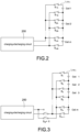
- FIG. 2 shows a block circuit diagram of a switch unit of a battery cell balance circuit according to a first embodiment of the present disclosure.
- the battery cell balance circuit includes a plurality of (m) battery cells Cell 1-Cell m, and the battery cells Cell 1-Cell m are connected in series to form a battery link L CELL .
- each battery cell Cell 1-Cell m are respectively connected to a switch unit, that is, a positive end of a first battery cell Cell 1 is connected to a switch unit S 1A and a negative end of the first battery cell Cell 1 is connected to a switch unit S 1B , and a positive end of a second battery cell Cell 2 is connected to a switch unit S 2A and a negative end of the second battery cell Cell 2 is connected to a switch unit S 2B , and so on, the number of switch units is twice the number of battery cells. For example, if the number of the battery cells Cell 1-Cell m is 18, the number of the switch units is 36. In FIG.
- the battery cells Cell 1-Cell m are connected to a charging-discharging circuit 200.
- positive ends of the battery cells Cell 1-Cell m are respectively connected to positive supplying ends or positive receiving ends of the charging-discharging circuit 200 through the switch units S 1A -S mA .
- negative ends of the battery cells Cell 1-Cell m are respectively connected to negative supplying ends or negative receiving ends of the charging-discharging circuit 200 through the switch units S 1B -S mB .
- the charging-discharging circuit 200 shown in FIG. 2 is used to provide a charging operation when a voltage of the battery cells Cell 1-Cell m (at least one of them) is too low to be charged, or a discharging operation when the voltage is too high to be discharged. That is, the charging-discharging circuit 200 may be, for example, but not limited to, a circuit having both charging and discharging functions, or two sets of circuits with separate charging and discharging functions.
- FIG. 3 shows a block circuit diagram of the switch unit of the battery cell balance circuit according to a second embodiment of the present disclosure.
- the battery cell balance circuit includes a plurality of (m) battery cells Cell 1-Cell m, and the battery cells Cell 1-Cell m are connected in series to form a battery link L CELL .
- a positive end of the first battery cell Cell 1 is connected to a switch unit S 1
- a negative end of the last battery cell Cell m is connected to a switch unit S m+1
- the positive end and the negative end of the middle (the remaining) battery cells Cell 2 to Cell m-1 jointly connected to a switch unit S 2 -S m .
- a switch assembly Sa composed of four switch units (described in detail later), the charging and discharging operations of the battery cells Cell 1-Cell m are realized. Therefore, the number of the switch units is five more than the number of the battery cells. For example, if the number of the battery cells Cell 1-Cell m is 18, the number of the switch units is 23.
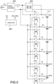
- FIG. 4 shows a block circuit diagram of the switch unit of the battery cell balance circuit according to a third embodiment of the present disclosure.
- the switch units shown in FIG. 4 are realized by electromagnetic relays RL1-RL6 (take the battery link L CELL with 6 battery cells as an example).
- the excitation control of the electromagnetic relays RL1-RL6 is used so that the effect of turning on and turning off is implemented, and a path for charging and discharging operations of the battery cells Cell 1-Cell 6 is provided.
- the battery cell balance circuit mainly includes an AC/DC converter 300, a plurality of battery cells Cell 1-Cell 6, a plurality of switch units RL1-RL6, an isolated DC/DC converter 400, a control unit 500.
- the AC/DC converter 300 receives an AC power V AC , and converts the AC power V AC into a DC power.
- the battery cells Cell 1-Cell 6 are connected in series to form a battery link L CELL .
- Each of the switch units RL1-RL6 is correspondingly connected to each of the battery cells Cell 1-Cell 6.
- FIG. 1 the battery cell balance circuit
- each switch unit RL1 - RL6 is an electromagnetic relay, which uses the principle of electromagnetic effect to excite the coil to change states of the contact to implement the turned-on and the turned-off function.
- the number of switch units RL1-RL6 is the same as that of battery cells Cell 1-Cell 6, that is, the first battery cell Cell 1 is connected to the first switch unit RL1, the second battery cell Cell 2 is connected to the second switch unit RL2, and so on.
- An input side of the isolated DC/DC converter 400 is coupled in parallel to an input side of each of the switches RL1-RL6.
- the input side of the isolated DC/DC converter 400 has a positive end and a negative end, and the positive end is connected to a positive end of the DC power converted from the AC/DC converter 300 and the negative end is connected to a negative end of the DC power.
- Each electromagnetic relay has a first side and a second side, and the first side and the second side have a positive end and a negative end, respectively.
- the positive end of the first side is coupled to the positive end of the DC power and the positive end of the input side of the isolated DC/DC converter 400
- the negative end of the first side is coupled to the negative end of the DC power and the negative end of the input side of the isolated DC/DC converter 400
- the positive end and the negative end of the second side are correspondingly connected to the positive ends and the negative ends of the battery cells, respectively.
- the positive ends of the first sides of all the electromagnetic relays are jointly coupled, and then coupled to the positive end of the DC power and the positive end of the input side of the isolated DC/DC converter 400.
- the negative ends of the first sides of all the electromagnetic relays are jointly coupled, and then coupled to the negative end of the DC power and the negative end of the input side of the isolated DC/DC converter 400.
- an output side of the isolated DC/DC converter 400 is coupled in series to the battery link L CELL .
- the output side of the isolated DC/DC converter 400 has a positive end and a negative end, and the positive end is coupled to a positive end of the battery link L CELL (i.e., a positive end of the first battery cell Cell 1) and the negative end is coupled to a negative end of the battery link L CELL (i.e., a negative end of the sixth battery cell Cell 6) so that the output side of the isolated DC/DC converter 400 is coupled in series to the battery link L CELL .
- the circuit switch Sc is coupled between the AC/DC converter 300 and the isolated DC/DC converter 400, that is, between the AC/DC converter 300 and the switch units RL1-RL6.
- the circuit switch Sc may be, for example, but not limited to, an electromagnetic relay or a transistor switch, such as a MOSFET.
- the battery voltage of any one of the battery cells Cell 1-Cell 6 is too high (abnormally high) during the charging process, the electrical energy of the battery cell with the too-high battery voltage is released to the battery link L CELL so that battery voltage of the battery cell is reduced and the battery cell is not over charged.
- the AC power V AC provides electrical energy to the battery cell with the too-low battery voltage so that the battery voltage of the battery cell is increased and the battery cell is not over discharged.
- the control unit 500 detects that a battery voltage of any one of the battery cells Cell 1-Cell 6 is greater than the upper threshold voltage, the control unit 500 provides switch control signals SRL1-SRL6 to turn on the switch unit RL1-RL6 corresponding to the battery cell with the too-high battery voltage so that the electrical energy of the battery cell Cell 1-Cell 6 with the too-high battery voltage is released to the battery link L CELL through the isolated DC/DC converter 400.
- the control unit 500 detects that the battery voltage of the first battery cell Cell 1 is too high (i.e., the battery voltage is greater than the upper threshold voltage)
- the control unit 500 turns on the first switch unit RL1 by the first switch control signal SRL1 so that the electrical energy of the first battery cell is released to the battery link L CELL through the first switch unit RL1 and the isolated DC/DC converter 400.
- the electrical energy of the first battery cell Cell 1 can also be used as the electrical energy for charging the battery link L CELL without wasting.
- the operation principles of other battery cells are the same as those described above, and the detail description is omitted here for conciseness.
- the control unit 500 detects that a battery voltage of any one of the battery cells Cell 1-Cell 6 is less than the lower threshold voltage, the control unit 500 provides a switch control signal Sec to turn on the circuit switch Sc, and provides switch control signals SRL1-SRL6 to turn on the switch unit RL1-RL6 corresponding to the battery cell with the too-low battery voltage so that the battery cell Cell 1-Cell 6 with the too-low battery voltage receives electrical energy provided from the AC power V AC .
- the lower threshold voltage is less than the upper threshold voltage.
- the control unit 500 when the control unit 500 detects that the battery voltage of the first battery cell Cell 1 is too low (i.e., the battery voltage is less than the lower threshold voltage), the control unit 500 turns on the circuit switch Sc by the switch control signal Scc, and turns on the first switch unit RL1 by the first switch control signal SRL1 so that the AC power V AC supplies power to the first battery cell Cell 1 (i.e., provides the electrical energy to the first battery cell Cell 1) through the circuit switch Sc and the first switch unit RL1, thereby increasing the battery voltage of the first battery cell Cell 1 to prevent over-discharging.
- the operation principles of other battery cells are the same as those described above, and the detail description is omitted here for conciseness.
- the battery voltage is adjusted through the release and supplement of electrical energy for the more seriously aged battery cells, that is, when the battery voltage of the battery cell is too high, the electrical energy is transmitted to the battery link, and when the battery voltage of the battery cell is too low, the electrical energy is supplemented by the AC power. Therefore, the battery voltage of the more severely aged battery cells during the charging and discharging processes can be maintained to be approximately the same as the battery voltage of other battery cells so as to ensure the normal operation of the overall battery module. Accordingly, in the application of the energy storage system, the operation of the battery module can be continuously maintained without requiring frequent replacement of battery cells. Until the annual repair, the seriously aged battery cells will be replaced in order to improve the economic benefits of the application of the energy storage system.
- the battery cell balance circuit further includes a plurality of over-current protection components correspondingly coupled to the battery cells Cell 1-Cell 6.
- the over-current protection components are fuses F1-F7. During the charging and discharging process, if an overcurrent abnormality occurs, an overcurrent protection can be provided through the corresponding fuses F1-F7 to protect the battery cells Cell 1-Cell 6.
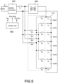
- FIG. 5 shows a block circuit diagram of the battery cell balance circuit according to a preferred embodiment of the present disclosure, and the FIG. 5 is cooperated with the embodiment shown in FIG. 3 (i.e., the second embodiment of the switch unit).
- the battery cell balance circuit mainly includes an AC/DC converter 300, an isolated DC/DC converter 400, a control unit 500, a plurality of (6) battery cells Cell 1-Cell 6 (connected in series to form a battery link L CELL ), a plurality of (7) switch units S 1 -S 7 , and a switch assembly Sa having a plurality of switch units Sa1, Sa2, Sb1, Sb2.
- the control unit 500 provides switch control signals S1c-S7c to correspondingly control the switch units S 1 -S 7 , provides switching switch control signals Salc-Sb2c to correspondingly control the switch units Sa1, Sa2, Sb1, Sb2, and provides a switch control signal S CC to control the circuit switch S C .
- the number of switch units may be significantly reduced (as described in FIG. 3 above). Therefore, with the turning on and turning off the switch units Sa1, Sa2, Sb1, Sb2, a path for providing the charging and discharging operations of the battery cells Cell 1-Cell 6 can be implemented.
- the control unit 500 detects that a battery voltage of any one of the battery cells Cell 1-Cell 6 is greater than the upper threshold voltage, the control unit 500 provides switch control signals S1c-S7c toturn on the switch unit S 1 -S 7 corresponding to the battery cell with the too-high battery voltage so that the electrical energy of the battery cell Cell 1-Cell 6 with the too-high battery voltage is released to the battery link L CELL through the isolated DC/DC converter 400.
- the control unit 500 detects that the battery voltage of the first battery cell Cell 1 is too high (i.e., the battery voltage is greater than the upper threshold voltage)
- the control unit 500 turns on the first switching switch unit Sa1 by the first switching switch control signal Sa1c
- turns on the second switch unit S 2 by the second switch control signal S2c so that the electrical energy of the first battery cell is released to the battery link L CELL through the first switch unit S 1 , the second switch unit S 2 , the first switching switch unit Sa1, the second switching switch unit Sa2, and the isolated DC/DC converter 400.
- the electrical energy of the first battery cell Cell 1 can also be used as the electrical energy for charging the battery link L CELL without wasting.
- the control unit 500 detects that the battery voltage of the second battery cell Cell 2 is too high (i.e., the battery voltage is greater than the upper threshold voltage)
- the control unit 500 turns on the third switching switch unit Sb1 by the third switching switch control signal Sb1c
- the electrical energy of the second battery cell Cell 2 can also be used as the electrical energy for charging the battery link L CELL without wasting.
- the control unit 500 detects that a battery voltage of any one of the battery cells Cell 1-Cell 6 is less than the lower threshold voltage, the control unit 500 provides a switch control signal S CC to turn on the circuit switch S C , and provides switch control signals S1c-S7c to turn on the switch unit S 1 -S 7 corresponding to the battery cell with the too-low battery voltage so that the battery cell Cell 1-Cell 6 with the too-low battery voltage receives electrical energy provided from the AC power V AC .
- the control unit 500 when the control unit 500 detects that the battery voltage of the first battery cell Cell 1 is too low (i.e., the battery voltage is less than the lower threshold voltage), the control unit 500 turns on the circuit switch Sc by the switch control signal Scc, turns on the first switching switch unit Sa1 by the first switching switch control signal Sa1c, turns on the second switching switch unit Sa2 by the second switching switch control signal Sa2c, turns on the first switch unit S 1 by the first switch control signal S1c, and turns on the second switch unit S 2 by the second switch control signal S2c so that the AC power V AC supplies power to the first battery cell Cell 1 (i.e., provides the electrical energy to the first battery cell Cell 1) through the circuit switch S C , the first switching switch unit Sa1, the second switching switch unit Sa2, the first switch unit S 1 , and the second switch unit S 2 , thereby increasing the battery voltage of the first battery cell Cell 1 to prevent over-discharging.
- the switch control signal Scc when the control unit 500 detects that the battery voltage of the first battery cell Cell
- the control unit 500 when the control unit 500 detects that the battery voltage of the second battery cell Cell 2 is too low (i.e., the battery voltage is less than the lower threshold voltage), the control unit 500 turns on the circuit switch Sc by the switch control signal S CC , turns on the third switching switch unit Sb1 by the third switching switch control signal Sb1c, turns on the fourth switching switch unit Sb2 by the fourth switching switch control signal Sb2c, turns on the second switch unit S 2 by the second switch control signal S2c, and turns on the third switch unit S 3 by the third switch control signal S3c so that the AC power V AC supplies power to the second battery cell Cell 2 (i.e., provides the electrical energy to the second battery cell Cell 2) through the circuit switch S C , the third switching switch unit Sb1, the fourth switching switch unit Sb2, the second switch unit S 2 , and the third switch unit S 3 , thereby increasing the battery voltage of the second battery cell Cell 2 to prevent over-discharging.
- the control principle of the switch assembly Sa (including switching switch units Sa1,Sa2,Sb1,Sb2) and the switch units S 1 -S 7 of the battery cell balance circuit shown in FIG. 5 is: according to the positive end and the negative end of the DC power converted and outputted by the AC/DC converter 300, the positive end and the negative end of the battery cells Cell 1-Cell 6 with the too-high battery voltage (or too-low battery voltage) are consistent so as to implement the adjustment of the battery voltage through the energy release and energy replenishment for the seriously aged battery cells.
- the first embodiment of the switch unit shown in FIG. 2 may also be applied to the structure of FIG. 5 , and the control principle of the switch unit is similar to that of FIG. 5 , and the detail description is omitted here for conciseness.
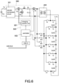
- FIG. 6 shows a detailed block circuit diagram of the battery cell balance circuit according to the preferred embodiment of the present disclosure.
- the AC/DC converter 300 includes an AC/DC conversion circuit 301 and a non-isolated DC/DC conversion.
- the non-isolated DC/DC conversion circuit is a step-down conversion circuit, which includes a switch S1, a switch S2, an inductor L1, a capacitor C1, and a resistor R1.
- the control unit 500 includes a charging control unit 501 and a controller 502 for controlling charging and discharging operations of the battery cells Cell 1-Cell 6.
- the battery cell balance circuit further includes a controller area network (CAN) involving a CAN IC and CAN bus. Therefore, the results of the detection and control of overall circuit by the control unit 500 are transmitted to the outside (external system) through the CAN so as to facilitate remote operators to acquire monitoring and control, thereby performing maintenance immediately to maintain the normal operation of the system.
- CAN controller area network
- FIG. 7 shows a flowchart of a method of operating the battery cell balance circuit according to the present disclosure.
- the battery cell balance circuit includes a plurality of battery cells connected in series to form a battery link, a plurality of switches, each of the switches correspondingly connected to each of the battery cells, and a circuit switch coupled between a DC power and the switches.
- the specific structure of the battery cell balance circuit may be found in the previous disclosure, and the detail description is omitted here for conciseness.
- the method of operating the battery cell balance circuit of the present disclosure includes steps of charging the battery cells (S11) and discharging the battery cells (S21).
Landscapes
- Engineering & Computer Science (AREA)
- Power Engineering (AREA)
- Charge And Discharge Circuits For Batteries Or The Like (AREA)
Applications Claiming Priority (2)
| Application Number | Priority Date | Filing Date | Title |
|---|---|---|---|
| US202163232925P | 2021-08-13 | 2021-08-13 | |
| CN202111579357.6A CN115706438A (zh) | 2021-08-13 | 2021-12-22 | 电池平衡电路及其操作方法 |
Publications (2)
| Publication Number | Publication Date |
|---|---|
| EP4135153A1 EP4135153A1 (en) | 2023-02-15 |
| EP4135153B1 true EP4135153B1 (en) | 2024-03-27 |
Family
ID=81851033
Family Applications (1)
| Application Number | Title | Priority Date | Filing Date |
|---|---|---|---|
| EP22175813.9A Active EP4135153B1 (en) | 2021-08-13 | 2022-05-27 | Battery cell balance circuit and method of operating the same |
Country Status (4)
| Country | Link |
|---|---|
| US (1) | US20230048191A1 (https=) |
| EP (1) | EP4135153B1 (https=) |
| JP (1) | JP7427051B2 (https=) |
| ES (1) | ES2977754T3 (https=) |
Families Citing this family (3)
| Publication number | Priority date | Publication date | Assignee | Title |
|---|---|---|---|---|
| US20240388107A1 (en) * | 2023-05-16 | 2024-11-21 | Infineon Technologies Ag | Battery management circuits with redundant power supply |
| CN118232487B (zh) * | 2024-05-24 | 2024-08-09 | 澄瑞电力科技(上海)股份公司 | 一种电池系统并联充放电控制方法 |
| CN119275970B (zh) * | 2024-10-21 | 2025-12-09 | 青岛攸能创科技有限公司 | 一种全钒液流电池acdc型均衡系统及其电能均衡方法 |
Family Cites Families (43)
| Publication number | Priority date | Publication date | Assignee | Title |
|---|---|---|---|---|
| JP3922655B2 (ja) * | 1996-07-12 | 2007-05-30 | 株式会社東京アールアンドデー | 電源装置の制御システムおよび電源装置の制御方法 |
| DE102004031216A1 (de) * | 2004-06-28 | 2006-01-19 | Siemens Ag | Vorrichtung und Verfahren zum Ladungsausgleich in Reihe geschalteter Energiespeicher |
| US7830117B2 (en) * | 2005-01-10 | 2010-11-09 | Odyne Systems, Llc | Vehicle charging, monitoring and control systems for electric and hybrid electric vehicles |
| JP4626828B2 (ja) * | 2007-11-01 | 2011-02-09 | 本田技研工業株式会社 | 放電制御装置 |
| JP2009159726A (ja) * | 2007-12-26 | 2009-07-16 | Honda Motor Co Ltd | 放電制御装置 |
| US8294421B2 (en) | 2008-09-05 | 2012-10-23 | O2Micro Inc | Cell balancing systems employing transformers |
| WO2010109956A1 (ja) * | 2009-03-27 | 2010-09-30 | 株式会社日立製作所 | 蓄電装置 |
| JP5567684B2 (ja) | 2009-12-14 | 2014-08-06 | リーチ インターナショナル コーポレイション | バッテリバランシング回路並びに第1の端子及び第2の端子を有するバッテリの複数のセルに蓄積されたエネルギーのバランシングを行う方法 |
| TWI424658B (zh) * | 2011-03-16 | 2014-01-21 | 台達電子工業股份有限公司 | 太陽能逆變器和太陽能逆變器之控制方法 |
| JP5641006B2 (ja) * | 2011-08-31 | 2014-12-17 | ソニー株式会社 | 蓄電装置 |
| TW201349731A (zh) * | 2012-05-30 | 2013-12-01 | 台達電子工業股份有限公司 | 具有發電模組之太陽能發電系統及其輸出電能控制方法 |
| US9172259B2 (en) | 2012-11-29 | 2015-10-27 | Samsung Sdi Co., Ltd. | Apparatus for managing battery, and energy storage system |
| WO2014115200A1 (ja) * | 2013-01-24 | 2014-07-31 | 三菱電機株式会社 | 蓄電池均等化装置 |
| DE102013106872A1 (de) | 2013-07-01 | 2015-01-08 | H-Tech Ag | Vorrichtung und Verfahren zum Ladungsausgleich einer Energiespeicheranordnung |
| CN105375539B (zh) | 2014-08-21 | 2021-02-09 | 上海稳得新能源科技有限公司 | 动力电池自动均衡充电器 |
| US9667073B2 (en) * | 2014-09-25 | 2017-05-30 | Texas Instruments Incorporated | Controlling polarity in an active balancing system for a battery |
| TWI581543B (zh) | 2014-10-03 | 2017-05-01 | 輝創電子股份有限公司 | 串聯電池組的主動平衡模組及其控制方法 |
| US9973099B2 (en) * | 2015-08-26 | 2018-05-15 | Futurewei Technologies, Inc. | AC/DC converters with wider voltage regulation range |
| JP2017063520A (ja) | 2015-09-24 | 2017-03-30 | アイシン精機株式会社 | 蓄電デバイス |
| US12062815B2 (en) * | 2015-09-30 | 2024-08-13 | Relectrify Holdings Pty Ltd | Battery system |
| US10063070B2 (en) * | 2016-11-25 | 2018-08-28 | National Chung Shan Institute Of Science And Technology | Battery active balancing system |
| US10720787B2 (en) * | 2017-07-26 | 2020-07-21 | Delta-Q Technologies Corp. | Combined charger and power converter |
| CN109494706A (zh) * | 2017-09-11 | 2019-03-19 | 台达电子工业股份有限公司 | 整合式供电系统 |
| JP7079129B2 (ja) * | 2018-03-28 | 2022-06-01 | 日立Astemo株式会社 | 車両用バッテリ装置 |
| TWI666851B (zh) | 2018-05-04 | 2019-07-21 | 大陸商東莞市高效電控有限公司 | 最佳化電池平衡系統及其操作方法 |
| KR102646285B1 (ko) * | 2018-12-21 | 2024-03-13 | 에스케이온 주식회사 | 배터리 시스템 |
| US11247582B2 (en) * | 2019-04-08 | 2022-02-15 | Samsung Sdi Co., Ltd. | Control electronics for a battery system, method for power supplying control electronics for a battery system, battery system and vehicle |
| US10615610B1 (en) * | 2019-05-28 | 2020-04-07 | Ekergy Llc | System and method for efficient charging of multiple battery cassettes |
| CN110460125A (zh) * | 2019-07-23 | 2019-11-15 | 华为技术有限公司 | 一种电池均衡电路及其控制方法、不间断电源供电系统 |
| CN110752635A (zh) * | 2019-10-12 | 2020-02-04 | 山东大学 | 串联电池组容量在线监测和充放电双状态均衡电路及方法 |
| CN111976538B (zh) | 2019-12-27 | 2022-09-20 | 中北大学 | 一种车载复合电源系统的均衡结构及其均衡方法 |
| CN113872258B (zh) * | 2020-06-30 | 2025-05-09 | 比亚迪股份有限公司 | 电池均流控制方法及电池均流控制系统 |
| JP7590837B2 (ja) * | 2020-09-16 | 2024-11-27 | 株式会社Subaru | 車両用電源装置 |
| JP7522618B2 (ja) * | 2020-09-16 | 2024-07-25 | 株式会社Subaru | 車両用電源装置 |
| WO2022198635A1 (zh) * | 2021-03-26 | 2022-09-29 | 华为数字能源技术有限公司 | 储能系统及其控制方法 |
| KR20230160873A (ko) * | 2021-04-09 | 2023-11-24 | 후아웨이 디지털 파워 테크놀러지스 컴퍼니 리미티드 | 에너지 저장 시스템, 에너지 저장 시스템을 제어하기 위한 방법, 및 태양광 발전 시스템 |
| CN113078714B (zh) | 2021-04-12 | 2023-09-22 | 华为数字能源技术有限公司 | 一种储能系统及储能系统控制方法 |
| CN113270881B (zh) * | 2021-04-23 | 2024-06-18 | 华为数字能源技术有限公司 | 一种储能系统、储能系统的均衡控制方法及光伏发电系统 |
| JPWO2022259897A1 (https=) * | 2021-06-10 | 2022-12-15 | ||
| CN116111847B (zh) * | 2021-11-10 | 2025-07-08 | 台达电子工业股份有限公司 | 转换模块的辅助电源电路、平衡电路与供电系统 |
| US20230268755A1 (en) * | 2022-02-18 | 2023-08-24 | Contemporary Amperex Technology Co., Limited | Energy storage system |
| WO2023178463A1 (zh) * | 2022-03-21 | 2023-09-28 | 宁德时代新能源科技股份有限公司 | 一种电池系统的控制方法、控制设备及电池系统 |
| CN116316971A (zh) * | 2023-02-24 | 2023-06-23 | 华为数字能源技术有限公司 | 一种均衡电路、电池包和储能系统 |
-
2022
- 2022-05-23 US US17/751,414 patent/US20230048191A1/en active Pending
- 2022-05-24 JP JP2022084551A patent/JP7427051B2/ja active Active
- 2022-05-27 EP EP22175813.9A patent/EP4135153B1/en active Active
- 2022-05-27 ES ES22175813T patent/ES2977754T3/es active Active
Also Published As
| Publication number | Publication date |
|---|---|
| US20230048191A1 (en) | 2023-02-16 |
| JP2023026313A (ja) | 2023-02-24 |
| EP4135153A1 (en) | 2023-02-15 |
| JP7427051B2 (ja) | 2024-02-02 |
| ES2977754T3 (es) | 2024-08-29 |
Similar Documents
| Publication | Publication Date | Title |
|---|---|---|
| EP4167423B1 (en) | Energy storage system | |
| EP4135153B1 (en) | Battery cell balance circuit and method of operating the same | |
| KR102084926B1 (ko) | 배터리 시스템 및 중간 전압 공급 방법 | |
| US8129952B2 (en) | Battery systems and operational methods | |
| EP2384530B1 (en) | Charge equalization apparatus for series-connected battery string using regulated voltage source | |
| KR101188944B1 (ko) | 다중 변압기의 2차 권선을 병렬로 연결한 전하 균일 장치 | |
| US8736231B2 (en) | Power management circuit for rechargeable battery stack | |
| US8269455B2 (en) | Charge balancing system | |
| KR101772975B1 (ko) | 셀 밸런싱 기능이 있는 배터리 모듈 및 그를 갖는 배터리 시스템 | |
| US20120286733A1 (en) | Battery system and battery equalizer | |
| US9099870B2 (en) | Charge redistribution method for cell arrays | |
| JP2013078242A (ja) | 電源装置 | |
| KR20230160873A (ko) | 에너지 저장 시스템, 에너지 저장 시스템을 제어하기 위한 방법, 및 태양광 발전 시스템 | |
| JP5596521B2 (ja) | 直流給電システム及び双方向電力変換装置 | |
| KR20160107173A (ko) | 전기화학 에너지 축전지 및 밸런싱 방법 | |
| CN118157286B (zh) | 一种电池均衡系统及电子设备 | |
| WO2021241136A1 (ja) | バックアップ電源装置 | |
| JP2023026313A5 (https=) | ||
| JP2009148110A (ja) | 充放電器とこれを用いた電源装置 | |
| KR101969301B1 (ko) | Dc 전력 계통용 배터리 충방전 제어 장치 | |
| TWI792793B (zh) | 電池平衡電路及其操作方法 | |
| JP2017127173A (ja) | 蓄電装置 | |
| US20220302743A1 (en) | Quick loading unit | |
| RU2156534C2 (ru) | Автономная система электроснабжения | |
| KR102399471B1 (ko) | 스위칭장치 및 배터리관리시스템 |
Legal Events
| Date | Code | Title | Description |
|---|---|---|---|
| PUAI | Public reference made under article 153(3) epc to a published international application that has entered the european phase |
Free format text: ORIGINAL CODE: 0009012 |
|
| STAA | Information on the status of an ep patent application or granted ep patent |
Free format text: STATUS: THE APPLICATION HAS BEEN PUBLISHED |
|
| AK | Designated contracting states |
Kind code of ref document: A1 Designated state(s): AL AT BE BG CH CY CZ DE DK EE ES FI FR GB GR HR HU IE IS IT LI LT LU LV MC MK MT NL NO PL PT RO RS SE SI SK SM TR |
|
| STAA | Information on the status of an ep patent application or granted ep patent |
Free format text: STATUS: REQUEST FOR EXAMINATION WAS MADE |
|
| 17P | Request for examination filed |
Effective date: 20230606 |
|
| RBV | Designated contracting states (corrected) |
Designated state(s): AL AT BE BG CH CY CZ DE DK EE ES FI FR GB GR HR HU IE IS IT LI LT LU LV MC MK MT NL NO PL PT RO RS SE SI SK SM TR |
|
| GRAP | Despatch of communication of intention to grant a patent |
Free format text: ORIGINAL CODE: EPIDOSNIGR1 |
|
| STAA | Information on the status of an ep patent application or granted ep patent |
Free format text: STATUS: GRANT OF PATENT IS INTENDED |
|
| INTG | Intention to grant announced |
Effective date: 20231031 |
|
| GRAS | Grant fee paid |
Free format text: ORIGINAL CODE: EPIDOSNIGR3 |
|
| GRAA | (expected) grant |
Free format text: ORIGINAL CODE: 0009210 |
|
| STAA | Information on the status of an ep patent application or granted ep patent |
Free format text: STATUS: THE PATENT HAS BEEN GRANTED |
|
| AK | Designated contracting states |
Kind code of ref document: B1 Designated state(s): AL AT BE BG CH CY CZ DE DK EE ES FI FR GB GR HR HU IE IS IT LI LT LU LV MC MK MT NL NO PL PT RO RS SE SI SK SM TR |
|
| REG | Reference to a national code |
Ref country code: GB Ref legal event code: FG4D |
|
| REG | Reference to a national code |
Ref country code: CH Ref legal event code: EP |
|
| REG | Reference to a national code |
Ref country code: DE Ref legal event code: R096 Ref document number: 602022002526 Country of ref document: DE |
|
| REG | Reference to a national code |
Ref country code: IE Ref legal event code: FG4D |
|
| REG | Reference to a national code |
Ref country code: NL Ref legal event code: FP |
|
| PG25 | Lapsed in a contracting state [announced via postgrant information from national office to epo] |
Ref country code: LT Free format text: LAPSE BECAUSE OF FAILURE TO SUBMIT A TRANSLATION OF THE DESCRIPTION OR TO PAY THE FEE WITHIN THE PRESCRIBED TIME-LIMIT Effective date: 20240327 |
|
| REG | Reference to a national code |
Ref country code: LT Ref legal event code: MG9D |
|
| PG25 | Lapsed in a contracting state [announced via postgrant information from national office to epo] |
Ref country code: GR Free format text: LAPSE BECAUSE OF FAILURE TO SUBMIT A TRANSLATION OF THE DESCRIPTION OR TO PAY THE FEE WITHIN THE PRESCRIBED TIME-LIMIT Effective date: 20240628 |
|
| PG25 | Lapsed in a contracting state [announced via postgrant information from national office to epo] |
Ref country code: RS Free format text: LAPSE BECAUSE OF FAILURE TO SUBMIT A TRANSLATION OF THE DESCRIPTION OR TO PAY THE FEE WITHIN THE PRESCRIBED TIME-LIMIT Effective date: 20240627 Ref country code: HR Free format text: LAPSE BECAUSE OF FAILURE TO SUBMIT A TRANSLATION OF THE DESCRIPTION OR TO PAY THE FEE WITHIN THE PRESCRIBED TIME-LIMIT Effective date: 20240327 |
|
| PG25 | Lapsed in a contracting state [announced via postgrant information from national office to epo] |
Ref country code: RS Free format text: LAPSE BECAUSE OF FAILURE TO SUBMIT A TRANSLATION OF THE DESCRIPTION OR TO PAY THE FEE WITHIN THE PRESCRIBED TIME-LIMIT Effective date: 20240627 Ref country code: NO Free format text: LAPSE BECAUSE OF FAILURE TO SUBMIT A TRANSLATION OF THE DESCRIPTION OR TO PAY THE FEE WITHIN THE PRESCRIBED TIME-LIMIT Effective date: 20240627 Ref country code: LT Free format text: LAPSE BECAUSE OF FAILURE TO SUBMIT A TRANSLATION OF THE DESCRIPTION OR TO PAY THE FEE WITHIN THE PRESCRIBED TIME-LIMIT Effective date: 20240327 Ref country code: HR Free format text: LAPSE BECAUSE OF FAILURE TO SUBMIT A TRANSLATION OF THE DESCRIPTION OR TO PAY THE FEE WITHIN THE PRESCRIBED TIME-LIMIT Effective date: 20240327 Ref country code: GR Free format text: LAPSE BECAUSE OF FAILURE TO SUBMIT A TRANSLATION OF THE DESCRIPTION OR TO PAY THE FEE WITHIN THE PRESCRIBED TIME-LIMIT Effective date: 20240628 Ref country code: FI Free format text: LAPSE BECAUSE OF FAILURE TO SUBMIT A TRANSLATION OF THE DESCRIPTION OR TO PAY THE FEE WITHIN THE PRESCRIBED TIME-LIMIT Effective date: 20240327 Ref country code: BG Free format text: LAPSE BECAUSE OF FAILURE TO SUBMIT A TRANSLATION OF THE DESCRIPTION OR TO PAY THE FEE WITHIN THE PRESCRIBED TIME-LIMIT Effective date: 20240327 |
|
| REG | Reference to a national code |
Ref country code: ES Ref legal event code: FG2A Ref document number: 2977754 Country of ref document: ES Kind code of ref document: T3 Effective date: 20240829 |
|
| PG25 | Lapsed in a contracting state [announced via postgrant information from national office to epo] |
Ref country code: SE Free format text: LAPSE BECAUSE OF FAILURE TO SUBMIT A TRANSLATION OF THE DESCRIPTION OR TO PAY THE FEE WITHIN THE PRESCRIBED TIME-LIMIT Effective date: 20240327 Ref country code: LV Free format text: LAPSE BECAUSE OF FAILURE TO SUBMIT A TRANSLATION OF THE DESCRIPTION OR TO PAY THE FEE WITHIN THE PRESCRIBED TIME-LIMIT Effective date: 20240327 |
|
| REG | Reference to a national code |
Ref country code: AT Ref legal event code: MK05 Ref document number: 1670855 Country of ref document: AT Kind code of ref document: T Effective date: 20240327 |
|
| PG25 | Lapsed in a contracting state [announced via postgrant information from national office to epo] |
Ref country code: IS Free format text: LAPSE BECAUSE OF FAILURE TO SUBMIT A TRANSLATION OF THE DESCRIPTION OR TO PAY THE FEE WITHIN THE PRESCRIBED TIME-LIMIT Effective date: 20240727 |
|
| PG25 | Lapsed in a contracting state [announced via postgrant information from national office to epo] |
Ref country code: SM Free format text: LAPSE BECAUSE OF FAILURE TO SUBMIT A TRANSLATION OF THE DESCRIPTION OR TO PAY THE FEE WITHIN THE PRESCRIBED TIME-LIMIT Effective date: 20240327 Ref country code: PT Free format text: LAPSE BECAUSE OF FAILURE TO SUBMIT A TRANSLATION OF THE DESCRIPTION OR TO PAY THE FEE WITHIN THE PRESCRIBED TIME-LIMIT Effective date: 20240729 |
|
| PG25 | Lapsed in a contracting state [announced via postgrant information from national office to epo] |
Ref country code: CZ Free format text: LAPSE BECAUSE OF FAILURE TO SUBMIT A TRANSLATION OF THE DESCRIPTION OR TO PAY THE FEE WITHIN THE PRESCRIBED TIME-LIMIT Effective date: 20240327 Ref country code: EE Free format text: LAPSE BECAUSE OF FAILURE TO SUBMIT A TRANSLATION OF THE DESCRIPTION OR TO PAY THE FEE WITHIN THE PRESCRIBED TIME-LIMIT Effective date: 20240327 |
|
| PG25 | Lapsed in a contracting state [announced via postgrant information from national office to epo] |
Ref country code: AT Free format text: LAPSE BECAUSE OF FAILURE TO SUBMIT A TRANSLATION OF THE DESCRIPTION OR TO PAY THE FEE WITHIN THE PRESCRIBED TIME-LIMIT Effective date: 20240327 |
|
| PG25 | Lapsed in a contracting state [announced via postgrant information from national office to epo] |
Ref country code: PL Free format text: LAPSE BECAUSE OF FAILURE TO SUBMIT A TRANSLATION OF THE DESCRIPTION OR TO PAY THE FEE WITHIN THE PRESCRIBED TIME-LIMIT Effective date: 20240327 |
|
| PG25 | Lapsed in a contracting state [announced via postgrant information from national office to epo] |
Ref country code: SK Free format text: LAPSE BECAUSE OF FAILURE TO SUBMIT A TRANSLATION OF THE DESCRIPTION OR TO PAY THE FEE WITHIN THE PRESCRIBED TIME-LIMIT Effective date: 20240327 |
|
| PG25 | Lapsed in a contracting state [announced via postgrant information from national office to epo] |
Ref country code: SM Free format text: LAPSE BECAUSE OF FAILURE TO SUBMIT A TRANSLATION OF THE DESCRIPTION OR TO PAY THE FEE WITHIN THE PRESCRIBED TIME-LIMIT Effective date: 20240327 Ref country code: SK Free format text: LAPSE BECAUSE OF FAILURE TO SUBMIT A TRANSLATION OF THE DESCRIPTION OR TO PAY THE FEE WITHIN THE PRESCRIBED TIME-LIMIT Effective date: 20240327 Ref country code: RO Free format text: LAPSE BECAUSE OF FAILURE TO SUBMIT A TRANSLATION OF THE DESCRIPTION OR TO PAY THE FEE WITHIN THE PRESCRIBED TIME-LIMIT Effective date: 20240327 Ref country code: PT Free format text: LAPSE BECAUSE OF FAILURE TO SUBMIT A TRANSLATION OF THE DESCRIPTION OR TO PAY THE FEE WITHIN THE PRESCRIBED TIME-LIMIT Effective date: 20240729 Ref country code: PL Free format text: LAPSE BECAUSE OF FAILURE TO SUBMIT A TRANSLATION OF THE DESCRIPTION OR TO PAY THE FEE WITHIN THE PRESCRIBED TIME-LIMIT Effective date: 20240327 Ref country code: IS Free format text: LAPSE BECAUSE OF FAILURE TO SUBMIT A TRANSLATION OF THE DESCRIPTION OR TO PAY THE FEE WITHIN THE PRESCRIBED TIME-LIMIT Effective date: 20240727 Ref country code: EE Free format text: LAPSE BECAUSE OF FAILURE TO SUBMIT A TRANSLATION OF THE DESCRIPTION OR TO PAY THE FEE WITHIN THE PRESCRIBED TIME-LIMIT Effective date: 20240327 Ref country code: CZ Free format text: LAPSE BECAUSE OF FAILURE TO SUBMIT A TRANSLATION OF THE DESCRIPTION OR TO PAY THE FEE WITHIN THE PRESCRIBED TIME-LIMIT Effective date: 20240327 Ref country code: AT Free format text: LAPSE BECAUSE OF FAILURE TO SUBMIT A TRANSLATION OF THE DESCRIPTION OR TO PAY THE FEE WITHIN THE PRESCRIBED TIME-LIMIT Effective date: 20240327 |
|
| REG | Reference to a national code |
Ref country code: DE Ref legal event code: R097 Ref document number: 602022002526 Country of ref document: DE |
|
| PG25 | Lapsed in a contracting state [announced via postgrant information from national office to epo] |
Ref country code: MC Free format text: LAPSE BECAUSE OF FAILURE TO SUBMIT A TRANSLATION OF THE DESCRIPTION OR TO PAY THE FEE WITHIN THE PRESCRIBED TIME-LIMIT Effective date: 20240327 |
|
| PG25 | Lapsed in a contracting state [announced via postgrant information from national office to epo] |
Ref country code: DK Free format text: LAPSE BECAUSE OF FAILURE TO SUBMIT A TRANSLATION OF THE DESCRIPTION OR TO PAY THE FEE WITHIN THE PRESCRIBED TIME-LIMIT Effective date: 20240327 |
|
| PG25 | Lapsed in a contracting state [announced via postgrant information from national office to epo] |
Ref country code: LU Free format text: LAPSE BECAUSE OF NON-PAYMENT OF DUE FEES Effective date: 20240527 |
|
| PG25 | Lapsed in a contracting state [announced via postgrant information from national office to epo] |
Ref country code: MC Free format text: LAPSE BECAUSE OF FAILURE TO SUBMIT A TRANSLATION OF THE DESCRIPTION OR TO PAY THE FEE WITHIN THE PRESCRIBED TIME-LIMIT Effective date: 20240327 Ref country code: LU Free format text: LAPSE BECAUSE OF NON-PAYMENT OF DUE FEES Effective date: 20240527 Ref country code: DK Free format text: LAPSE BECAUSE OF FAILURE TO SUBMIT A TRANSLATION OF THE DESCRIPTION OR TO PAY THE FEE WITHIN THE PRESCRIBED TIME-LIMIT Effective date: 20240327 |
|
| PLBE | No opposition filed within time limit |
Free format text: ORIGINAL CODE: 0009261 |
|
| STAA | Information on the status of an ep patent application or granted ep patent |
Free format text: STATUS: NO OPPOSITION FILED WITHIN TIME LIMIT |
|
| REG | Reference to a national code |
Ref country code: BE Ref legal event code: MM Effective date: 20240531 |
|
| 26N | No opposition filed |
Effective date: 20250103 |
|
| PG25 | Lapsed in a contracting state [announced via postgrant information from national office to epo] |
Ref country code: IE Free format text: LAPSE BECAUSE OF NON-PAYMENT OF DUE FEES Effective date: 20240527 |
|
| PG25 | Lapsed in a contracting state [announced via postgrant information from national office to epo] |
Ref country code: SI Free format text: LAPSE BECAUSE OF FAILURE TO SUBMIT A TRANSLATION OF THE DESCRIPTION OR TO PAY THE FEE WITHIN THE PRESCRIBED TIME-LIMIT Effective date: 20240327 Ref country code: BE Free format text: LAPSE BECAUSE OF NON-PAYMENT OF DUE FEES Effective date: 20240531 |
|
| PGFP | Annual fee paid to national office [announced via postgrant information from national office to epo] |
Ref country code: NL Payment date: 20250409 Year of fee payment: 4 |
|
| PGFP | Annual fee paid to national office [announced via postgrant information from national office to epo] |
Ref country code: DE Payment date: 20250402 Year of fee payment: 4 |
|
| PGFP | Annual fee paid to national office [announced via postgrant information from national office to epo] |
Ref country code: ES Payment date: 20250603 Year of fee payment: 4 |
|
| PGFP | Annual fee paid to national office [announced via postgrant information from national office to epo] |
Ref country code: IT Payment date: 20250531 Year of fee payment: 4 |
|
| PGFP | Annual fee paid to national office [announced via postgrant information from national office to epo] |
Ref country code: FR Payment date: 20250401 Year of fee payment: 4 |
|
| PG25 | Lapsed in a contracting state [announced via postgrant information from national office to epo] |
Ref country code: HU Free format text: LAPSE BECAUSE OF FAILURE TO SUBMIT A TRANSLATION OF THE DESCRIPTION OR TO PAY THE FEE WITHIN THE PRESCRIBED TIME-LIMIT; INVALID AB INITIO Effective date: 20220527 |
|
| PG25 | Lapsed in a contracting state [announced via postgrant information from national office to epo] |
Ref country code: CY Free format text: LAPSE BECAUSE OF FAILURE TO SUBMIT A TRANSLATION OF THE DESCRIPTION OR TO PAY THE FEE WITHIN THE PRESCRIBED TIME-LIMIT; INVALID AB INITIO Effective date: 20220527 |
|
| REG | Reference to a national code |
Ref country code: CH Ref legal event code: H13 Free format text: ST27 STATUS EVENT CODE: U-0-0-H10-H13 (AS PROVIDED BY THE NATIONAL OFFICE) Effective date: 20251223 |
|
| PG25 | Lapsed in a contracting state [announced via postgrant information from national office to epo] |
Ref country code: CH Free format text: LAPSE BECAUSE OF NON-PAYMENT OF DUE FEES Effective date: 20250531 |