EP4135153B1 - Battery cell balance circuit and method of operating the same - Google Patents
Battery cell balance circuit and method of operating the same Download PDFInfo
- Publication number
- EP4135153B1 EP4135153B1 EP22175813.9A EP22175813A EP4135153B1 EP 4135153 B1 EP4135153 B1 EP 4135153B1 EP 22175813 A EP22175813 A EP 22175813A EP 4135153 B1 EP4135153 B1 EP 4135153B1
- Authority
- EP
- European Patent Office
- Prior art keywords
- cell
- battery
- switch
- switches
- battery cells
- Prior art date
- Legal status (The legal status is an assumption and is not a legal conclusion. Google has not performed a legal analysis and makes no representation as to the accuracy of the status listed.)
- Active
Links
- 238000000034 method Methods 0.000 title claims description 31
- 238000007599 discharging Methods 0.000 claims description 31
- 238000006243 chemical reaction Methods 0.000 claims description 8
- 230000008569 process Effects 0.000 description 14
- 238000010586 diagram Methods 0.000 description 12
- 238000004146 energy storage Methods 0.000 description 10
- 238000005516 engineering process Methods 0.000 description 8
- 230000008901 benefit Effects 0.000 description 5
- 230000000694 effects Effects 0.000 description 4
- 230000008439 repair process Effects 0.000 description 3
- 239000013589 supplement Substances 0.000 description 3
- 101150096245 SRL1 gene Proteins 0.000 description 2
- 239000003990 capacitor Substances 0.000 description 2
- 239000007787 solid Substances 0.000 description 2
- 230000002159 abnormal effect Effects 0.000 description 1
- 230000005856 abnormality Effects 0.000 description 1
- 230000008859 change Effects 0.000 description 1
- 230000001419 dependent effect Effects 0.000 description 1
- 238000001514 detection method Methods 0.000 description 1
- 230000005288 electromagnetic effect Effects 0.000 description 1
- 238000005265 energy consumption Methods 0.000 description 1
- 230000005284 excitation Effects 0.000 description 1
- 238000012423 maintenance Methods 0.000 description 1
- 238000012544 monitoring process Methods 0.000 description 1
- 238000004806 packaging method and process Methods 0.000 description 1
Images


Classifications
-
- H—ELECTRICITY
- H02—GENERATION; CONVERSION OR DISTRIBUTION OF ELECTRIC POWER
- H02J—CIRCUIT ARRANGEMENTS OR SYSTEMS FOR SUPPLYING OR DISTRIBUTING ELECTRIC POWER; SYSTEMS FOR STORING ELECTRIC ENERGY
- H02J7/00—Circuit arrangements for charging or depolarising batteries or for supplying loads from batteries
- H02J7/0013—Circuit arrangements for charging or depolarising batteries or for supplying loads from batteries acting upon several batteries simultaneously or sequentially
- H02J7/0014—Circuits for equalisation of charge between batteries
- H02J7/0016—Circuits for equalisation of charge between batteries using shunting, discharge or bypass circuits
-
- H—ELECTRICITY
- H02—GENERATION; CONVERSION OR DISTRIBUTION OF ELECTRIC POWER
- H02J—CIRCUIT ARRANGEMENTS OR SYSTEMS FOR SUPPLYING OR DISTRIBUTING ELECTRIC POWER; SYSTEMS FOR STORING ELECTRIC ENERGY
- H02J7/00—Circuit arrangements for charging or depolarising batteries or for supplying loads from batteries
- H02J7/0013—Circuit arrangements for charging or depolarising batteries or for supplying loads from batteries acting upon several batteries simultaneously or sequentially
- H02J7/0014—Circuits for equalisation of charge between batteries
- H02J7/0019—Circuits for equalisation of charge between batteries using switched or multiplexed charge circuits
-
- H—ELECTRICITY
- H02—GENERATION; CONVERSION OR DISTRIBUTION OF ELECTRIC POWER
- H02J—CIRCUIT ARRANGEMENTS OR SYSTEMS FOR SUPPLYING OR DISTRIBUTING ELECTRIC POWER; SYSTEMS FOR STORING ELECTRIC ENERGY
- H02J7/00—Circuit arrangements for charging or depolarising batteries or for supplying loads from batteries
- H02J7/0029—Circuit arrangements for charging or depolarising batteries or for supplying loads from batteries with safety or protection devices or circuits
- H02J7/00304—Overcurrent protection
-
- H—ELECTRICITY
- H02—GENERATION; CONVERSION OR DISTRIBUTION OF ELECTRIC POWER
- H02J—CIRCUIT ARRANGEMENTS OR SYSTEMS FOR SUPPLYING OR DISTRIBUTING ELECTRIC POWER; SYSTEMS FOR STORING ELECTRIC ENERGY
- H02J7/00—Circuit arrangements for charging or depolarising batteries or for supplying loads from batteries
- H02J7/0047—Circuit arrangements for charging or depolarising batteries or for supplying loads from batteries with monitoring or indicating devices or circuits
-
- H—ELECTRICITY
- H02—GENERATION; CONVERSION OR DISTRIBUTION OF ELECTRIC POWER
- H02J—CIRCUIT ARRANGEMENTS OR SYSTEMS FOR SUPPLYING OR DISTRIBUTING ELECTRIC POWER; SYSTEMS FOR STORING ELECTRIC ENERGY
- H02J7/00—Circuit arrangements for charging or depolarising batteries or for supplying loads from batteries
- H02J7/02—Circuit arrangements for charging or depolarising batteries or for supplying loads from batteries for charging batteries from ac mains by converters
-
- H—ELECTRICITY
- H02—GENERATION; CONVERSION OR DISTRIBUTION OF ELECTRIC POWER
- H02M—APPARATUS FOR CONVERSION BETWEEN AC AND AC, BETWEEN AC AND DC, OR BETWEEN DC AND DC, AND FOR USE WITH MAINS OR SIMILAR POWER SUPPLY SYSTEMS; CONVERSION OF DC OR AC INPUT POWER INTO SURGE OUTPUT POWER; CONTROL OR REGULATION THEREOF
- H02M3/00—Conversion of dc power input into dc power output
- H02M3/02—Conversion of dc power input into dc power output without intermediate conversion into ac
- H02M3/04—Conversion of dc power input into dc power output without intermediate conversion into ac by static converters
- H02M3/10—Conversion of dc power input into dc power output without intermediate conversion into ac by static converters using discharge tubes with control electrode or semiconductor devices with control electrode
- H02M3/145—Conversion of dc power input into dc power output without intermediate conversion into ac by static converters using discharge tubes with control electrode or semiconductor devices with control electrode using devices of a triode or transistor type requiring continuous application of a control signal
- H02M3/155—Conversion of dc power input into dc power output without intermediate conversion into ac by static converters using discharge tubes with control electrode or semiconductor devices with control electrode using devices of a triode or transistor type requiring continuous application of a control signal using semiconductor devices only
- H02M3/156—Conversion of dc power input into dc power output without intermediate conversion into ac by static converters using discharge tubes with control electrode or semiconductor devices with control electrode using devices of a triode or transistor type requiring continuous application of a control signal using semiconductor devices only with automatic control of output voltage or current, e.g. switching regulators
- H02M3/158—Conversion of dc power input into dc power output without intermediate conversion into ac by static converters using discharge tubes with control electrode or semiconductor devices with control electrode using devices of a triode or transistor type requiring continuous application of a control signal using semiconductor devices only with automatic control of output voltage or current, e.g. switching regulators including plural semiconductor devices as final control devices for a single load
-
- H—ELECTRICITY
- H01—ELECTRIC ELEMENTS
- H01M—PROCESSES OR MEANS, e.g. BATTERIES, FOR THE DIRECT CONVERSION OF CHEMICAL ENERGY INTO ELECTRICAL ENERGY
- H01M10/00—Secondary cells; Manufacture thereof
- H01M10/42—Methods or arrangements for servicing or maintenance of secondary cells or secondary half-cells
- H01M10/425—Structural combination with electronic components, e.g. electronic circuits integrated to the outside of the casing
- H01M2010/4271—Battery management systems including electronic circuits, e.g. control of current or voltage to keep battery in healthy state, cell balancing
-
- H—ELECTRICITY
- H02—GENERATION; CONVERSION OR DISTRIBUTION OF ELECTRIC POWER
- H02J—CIRCUIT ARRANGEMENTS OR SYSTEMS FOR SUPPLYING OR DISTRIBUTING ELECTRIC POWER; SYSTEMS FOR STORING ELECTRIC ENERGY
- H02J2207/00—Indexing scheme relating to details of circuit arrangements for charging or depolarising batteries or for supplying loads from batteries
- H02J2207/20—Charging or discharging characterised by the power electronics converter
-
- Y—GENERAL TAGGING OF NEW TECHNOLOGICAL DEVELOPMENTS; GENERAL TAGGING OF CROSS-SECTIONAL TECHNOLOGIES SPANNING OVER SEVERAL SECTIONS OF THE IPC; TECHNICAL SUBJECTS COVERED BY FORMER USPC CROSS-REFERENCE ART COLLECTIONS [XRACs] AND DIGESTS
- Y02—TECHNOLOGIES OR APPLICATIONS FOR MITIGATION OR ADAPTATION AGAINST CLIMATE CHANGE
- Y02E—REDUCTION OF GREENHOUSE GAS [GHG] EMISSIONS, RELATED TO ENERGY GENERATION, TRANSMISSION OR DISTRIBUTION
- Y02E60/00—Enabling technologies; Technologies with a potential or indirect contribution to GHG emissions mitigation
- Y02E60/10—Energy storage using batteries
Definitions
- the present disclosure relates to a battery cell balance circuit comprising a plurality of battery cells, and a plurality of switches, each of the switches correspondingly connected to each of the battery cells, an AC/DC converter, configured to receive an AC power and convert the AC power into a DC power, as known from CN 113 078 714 A .
- the present disclosure further relates to a method of operating the same, and more particularly to an active battery cell balance circuit and a method of operating the same. Further such circuits and methods are known from CN 110 752 635 A .
- FIG. 1 shows a perspective diagram of a battery module having a plurality of battery cells in the related art.
- Each battery module 100 has 18 battery cells 101-10N arranged in two rows and connected in series. Therefore, in the application of the energy storage system, parallel connection can be provided through multiple groups of battery modules 100 at the same time so as to achieve high-energy (high-power) and high-voltage power supply applications.
- a single battery cell 101-10N when the battery cell 101-10N ages, abnormal phenomena such as easy to be fully charged and easy to discharge will occur.
- the single battery module 100 shown in FIG. 1 it has 18 battery cells 101-10N. Once one of the battery cells ages in advance, the effect of charging and discharging of the more seriously aged battery cell on the other 17 battery cells will lie in: during charging, the charging voltage of the more seriously aged battery cell rapidly rises. Therefore, for the overall battery module 100, during the normal charging process, the more seriously aged battery cell may be over-charged (other battery cells may not be fully charged), or even damaged. Conversely, during discharging, the voltage of the more seriously aged battery cells rapidly drops. Therefore, for the overall battery module 100, during the normal discharging process, the more seriously aged battery cell may be over-discharged (other battery cells may not be fully discharged), or even damaged.
- An object of the present disclosure is to provide a battery cell balance circuit to solve the problems of existing technology.
- the battery cell balance circuit comprises an isolated DC/DC converter, an input side of the isolated DC/DC converter coupled in parallel to an input side of each of the switches, and an output side of the isolated DC/DC converter coupled to the a battery link, wherein the plurality of battery cells are connected in series to form a battery link, a circuit switch, coupled between the AC/DC converter, the isolated DC/DC converter, and the plurality of switches, and a control unit, configured to provide a plurality of control signals to correspondingly control the plurality of switches and the circuit switch.
- Another object of the present disclosure is to provide a method of operating a battery cell balance circuit to solve the problems of existing technology.
- the battery cell balance circuit includes a plurality of battery cells connected in series to form a battery link, a plurality of switches, each of the switches correspondingly connected to each of the battery cells, and a circuit switch coupled between a DC power and the switches.
- the method includes steps of: controlling the switch corresponding to the battery cell to be turned on when a battery voltage of any one of the battery cells is detected to be greater than an upper threshold voltage, releasing electrical energy of the battery cell to the battery link, controlling the circuit switch to be turned on and controlling the switch corresponding to the battery cell to be turned on when the battery voltage of any one of the battery cells is detected to be less than a lower threshold voltage, and receiving, by the battery cell, the electrical energy from the DC power.
- the battery voltage is adjusted through the release and supplement of electrical energy for the more seriously aged battery cells, that is, when the battery voltage of the battery cell is too high, the electrical energy is transmitted to the battery link, and when the battery voltage of the battery cell is too low, the electrical energy is supplemented by the AC power. Therefore, the battery voltage of the more severely aged battery cells during the charging and discharging processes can be maintained to be approximately the same as the battery voltage of other battery cells so as to ensure the normal operation of the overall battery module. Accordingly, in the application of the energy storage system, the operation of the battery module can be continuously maintained without requiring frequent replacement of battery cells. Until the annual repair, the seriously aged battery cells will be replaced in order to improve the economic benefits of the application of the energy storage system.
- the passive battery cell balance technology refers to the energy consumption of battery cells with higher voltage through energy-consuming components.
- the common practice is: each battery cell is connected in parallel with resistance components through the switch circuit, and the energy of the battery cells with higher voltage is consumed by controlling the conduction (turned-on) of the switch and the parallel resistance components, thereby reducing the battery voltage of the battery cells to achieve a voltage balance between the battery cells.
- the active battery cell balance technology refers to the redistribution of energy between cells. For example, using energy storage components (such as inductors or capacitors) to temporarily store the energy of the battery cells with higher voltage, and then release the temporarily stored energy to the battery cells with lower voltage to achieve the effect of voltage balance between the battery cells.
- energy storage components such as inductors or capacitors
- the present disclosure proposes different technical means to achieve the effect of active battery cell balance.
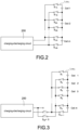
- FIG. 2 shows a block circuit diagram of a switch unit of a battery cell balance circuit according to a first embodiment of the present disclosure.
- the battery cell balance circuit includes a plurality of (m) battery cells Cell 1-Cell m, and the battery cells Cell 1-Cell m are connected in series to form a battery link L CELL .
- each battery cell Cell 1-Cell m are respectively connected to a switch unit, that is, a positive end of a first battery cell Cell 1 is connected to a switch unit S 1A and a negative end of the first battery cell Cell 1 is connected to a switch unit S 1B , and a positive end of a second battery cell Cell 2 is connected to a switch unit S 2A and a negative end of the second battery cell Cell 2 is connected to a switch unit S 2B , and so on, the number of switch units is twice the number of battery cells. For example, if the number of the battery cells Cell 1-Cell m is 18, the number of the switch units is 36. In FIG.
- the battery cells Cell 1-Cell m are connected to a charging-discharging circuit 200.
- positive ends of the battery cells Cell 1-Cell m are respectively connected to positive supplying ends or positive receiving ends of the charging-discharging circuit 200 through the switch units S 1A -S mA .
- negative ends of the battery cells Cell 1-Cell m are respectively connected to negative supplying ends or negative receiving ends of the charging-discharging circuit 200 through the switch units S 1B -S mB .
- the charging-discharging circuit 200 shown in FIG. 2 is used to provide a charging operation when a voltage of the battery cells Cell 1-Cell m (at least one of them) is too low to be charged, or a discharging operation when the voltage is too high to be discharged. That is, the charging-discharging circuit 200 may be, for example, but not limited to, a circuit having both charging and discharging functions, or two sets of circuits with separate charging and discharging functions.
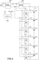
- FIG. 3 shows a block circuit diagram of the switch unit of the battery cell balance circuit according to a second embodiment of the present disclosure.
- the battery cell balance circuit includes a plurality of (m) battery cells Cell 1-Cell m, and the battery cells Cell 1-Cell m are connected in series to form a battery link L CELL .
- a positive end of the first battery cell Cell 1 is connected to a switch unit S 1
- a negative end of the last battery cell Cell m is connected to a switch unit S m+1
- the positive end and the negative end of the middle (the remaining) battery cells Cell 2 to Cell m-1 jointly connected to a switch unit S 2 -S m .
- a switch assembly Sa composed of four switch units (described in detail later), the charging and discharging operations of the battery cells Cell 1-Cell m are realized. Therefore, the number of the switch units is five more than the number of the battery cells. For example, if the number of the battery cells Cell 1-Cell m is 18, the number of the switch units is 23.
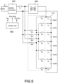
- FIG. 4 shows a block circuit diagram of the switch unit of the battery cell balance circuit according to a third embodiment of the present disclosure.
- the switch units shown in FIG. 4 are realized by electromagnetic relays RL1-RL6 (take the battery link L CELL with 6 battery cells as an example).
- the excitation control of the electromagnetic relays RL1-RL6 is used so that the effect of turning on and turning off is implemented, and a path for charging and discharging operations of the battery cells Cell 1-Cell 6 is provided.
- the battery cell balance circuit mainly includes an AC/DC converter 300, a plurality of battery cells Cell 1-Cell 6, a plurality of switch units RL1-RL6, an isolated DC/DC converter 400, a control unit 500.
- the AC/DC converter 300 receives an AC power V AC , and converts the AC power V AC into a DC power.
- the battery cells Cell 1-Cell 6 are connected in series to form a battery link L CELL .
- Each of the switch units RL1-RL6 is correspondingly connected to each of the battery cells Cell 1-Cell 6.
- FIG. 1 the battery cell balance circuit
- each switch unit RL1 - RL6 is an electromagnetic relay, which uses the principle of electromagnetic effect to excite the coil to change states of the contact to implement the turned-on and the turned-off function.
- the number of switch units RL1-RL6 is the same as that of battery cells Cell 1-Cell 6, that is, the first battery cell Cell 1 is connected to the first switch unit RL1, the second battery cell Cell 2 is connected to the second switch unit RL2, and so on.
- An input side of the isolated DC/DC converter 400 is coupled in parallel to an input side of each of the switches RL1-RL6.
- the input side of the isolated DC/DC converter 400 has a positive end and a negative end, and the positive end is connected to a positive end of the DC power converted from the AC/DC converter 300 and the negative end is connected to a negative end of the DC power.
- Each electromagnetic relay has a first side and a second side, and the first side and the second side have a positive end and a negative end, respectively.
- the positive end of the first side is coupled to the positive end of the DC power and the positive end of the input side of the isolated DC/DC converter 400
- the negative end of the first side is coupled to the negative end of the DC power and the negative end of the input side of the isolated DC/DC converter 400
- the positive end and the negative end of the second side are correspondingly connected to the positive ends and the negative ends of the battery cells, respectively.
- the positive ends of the first sides of all the electromagnetic relays are jointly coupled, and then coupled to the positive end of the DC power and the positive end of the input side of the isolated DC/DC converter 400.
- the negative ends of the first sides of all the electromagnetic relays are jointly coupled, and then coupled to the negative end of the DC power and the negative end of the input side of the isolated DC/DC converter 400.
- an output side of the isolated DC/DC converter 400 is coupled in series to the battery link L CELL .
- the output side of the isolated DC/DC converter 400 has a positive end and a negative end, and the positive end is coupled to a positive end of the battery link L CELL (i.e., a positive end of the first battery cell Cell 1) and the negative end is coupled to a negative end of the battery link L CELL (i.e., a negative end of the sixth battery cell Cell 6) so that the output side of the isolated DC/DC converter 400 is coupled in series to the battery link L CELL .
- the circuit switch Sc is coupled between the AC/DC converter 300 and the isolated DC/DC converter 400, that is, between the AC/DC converter 300 and the switch units RL1-RL6.
- the circuit switch Sc may be, for example, but not limited to, an electromagnetic relay or a transistor switch, such as a MOSFET.
- the battery voltage of any one of the battery cells Cell 1-Cell 6 is too high (abnormally high) during the charging process, the electrical energy of the battery cell with the too-high battery voltage is released to the battery link L CELL so that battery voltage of the battery cell is reduced and the battery cell is not over charged.
- the AC power V AC provides electrical energy to the battery cell with the too-low battery voltage so that the battery voltage of the battery cell is increased and the battery cell is not over discharged.
- the control unit 500 detects that a battery voltage of any one of the battery cells Cell 1-Cell 6 is greater than the upper threshold voltage, the control unit 500 provides switch control signals SRL1-SRL6 to turn on the switch unit RL1-RL6 corresponding to the battery cell with the too-high battery voltage so that the electrical energy of the battery cell Cell 1-Cell 6 with the too-high battery voltage is released to the battery link L CELL through the isolated DC/DC converter 400.
- the control unit 500 detects that the battery voltage of the first battery cell Cell 1 is too high (i.e., the battery voltage is greater than the upper threshold voltage)
- the control unit 500 turns on the first switch unit RL1 by the first switch control signal SRL1 so that the electrical energy of the first battery cell is released to the battery link L CELL through the first switch unit RL1 and the isolated DC/DC converter 400.
- the electrical energy of the first battery cell Cell 1 can also be used as the electrical energy for charging the battery link L CELL without wasting.
- the operation principles of other battery cells are the same as those described above, and the detail description is omitted here for conciseness.
- the control unit 500 detects that a battery voltage of any one of the battery cells Cell 1-Cell 6 is less than the lower threshold voltage, the control unit 500 provides a switch control signal Sec to turn on the circuit switch Sc, and provides switch control signals SRL1-SRL6 to turn on the switch unit RL1-RL6 corresponding to the battery cell with the too-low battery voltage so that the battery cell Cell 1-Cell 6 with the too-low battery voltage receives electrical energy provided from the AC power V AC .
- the lower threshold voltage is less than the upper threshold voltage.
- the control unit 500 when the control unit 500 detects that the battery voltage of the first battery cell Cell 1 is too low (i.e., the battery voltage is less than the lower threshold voltage), the control unit 500 turns on the circuit switch Sc by the switch control signal Scc, and turns on the first switch unit RL1 by the first switch control signal SRL1 so that the AC power V AC supplies power to the first battery cell Cell 1 (i.e., provides the electrical energy to the first battery cell Cell 1) through the circuit switch Sc and the first switch unit RL1, thereby increasing the battery voltage of the first battery cell Cell 1 to prevent over-discharging.
- the operation principles of other battery cells are the same as those described above, and the detail description is omitted here for conciseness.
- the battery voltage is adjusted through the release and supplement of electrical energy for the more seriously aged battery cells, that is, when the battery voltage of the battery cell is too high, the electrical energy is transmitted to the battery link, and when the battery voltage of the battery cell is too low, the electrical energy is supplemented by the AC power. Therefore, the battery voltage of the more severely aged battery cells during the charging and discharging processes can be maintained to be approximately the same as the battery voltage of other battery cells so as to ensure the normal operation of the overall battery module. Accordingly, in the application of the energy storage system, the operation of the battery module can be continuously maintained without requiring frequent replacement of battery cells. Until the annual repair, the seriously aged battery cells will be replaced in order to improve the economic benefits of the application of the energy storage system.
- the battery cell balance circuit further includes a plurality of over-current protection components correspondingly coupled to the battery cells Cell 1-Cell 6.
- the over-current protection components are fuses F1-F7. During the charging and discharging process, if an overcurrent abnormality occurs, an overcurrent protection can be provided through the corresponding fuses F1-F7 to protect the battery cells Cell 1-Cell 6.
- FIG. 5 shows a block circuit diagram of the battery cell balance circuit according to a preferred embodiment of the present disclosure, and the FIG. 5 is cooperated with the embodiment shown in FIG. 3 (i.e., the second embodiment of the switch unit).
- the battery cell balance circuit mainly includes an AC/DC converter 300, an isolated DC/DC converter 400, a control unit 500, a plurality of (6) battery cells Cell 1-Cell 6 (connected in series to form a battery link L CELL ), a plurality of (7) switch units S 1 -S 7 , and a switch assembly Sa having a plurality of switch units Sa1, Sa2, Sb1, Sb2.
- the control unit 500 provides switch control signals S1c-S7c to correspondingly control the switch units S 1 -S 7 , provides switching switch control signals Salc-Sb2c to correspondingly control the switch units Sa1, Sa2, Sb1, Sb2, and provides a switch control signal S CC to control the circuit switch S C .
- the number of switch units may be significantly reduced (as described in FIG. 3 above). Therefore, with the turning on and turning off the switch units Sa1, Sa2, Sb1, Sb2, a path for providing the charging and discharging operations of the battery cells Cell 1-Cell 6 can be implemented.
- the control unit 500 detects that a battery voltage of any one of the battery cells Cell 1-Cell 6 is greater than the upper threshold voltage, the control unit 500 provides switch control signals S1c-S7c toturn on the switch unit S 1 -S 7 corresponding to the battery cell with the too-high battery voltage so that the electrical energy of the battery cell Cell 1-Cell 6 with the too-high battery voltage is released to the battery link L CELL through the isolated DC/DC converter 400.
- the control unit 500 detects that the battery voltage of the first battery cell Cell 1 is too high (i.e., the battery voltage is greater than the upper threshold voltage)
- the control unit 500 turns on the first switching switch unit Sa1 by the first switching switch control signal Sa1c
- turns on the second switch unit S 2 by the second switch control signal S2c so that the electrical energy of the first battery cell is released to the battery link L CELL through the first switch unit S 1 , the second switch unit S 2 , the first switching switch unit Sa1, the second switching switch unit Sa2, and the isolated DC/DC converter 400.
- the electrical energy of the first battery cell Cell 1 can also be used as the electrical energy for charging the battery link L CELL without wasting.
- the control unit 500 detects that the battery voltage of the second battery cell Cell 2 is too high (i.e., the battery voltage is greater than the upper threshold voltage)
- the control unit 500 turns on the third switching switch unit Sb1 by the third switching switch control signal Sb1c
- the electrical energy of the second battery cell Cell 2 can also be used as the electrical energy for charging the battery link L CELL without wasting.
- the control unit 500 detects that a battery voltage of any one of the battery cells Cell 1-Cell 6 is less than the lower threshold voltage, the control unit 500 provides a switch control signal S CC to turn on the circuit switch S C , and provides switch control signals S1c-S7c to turn on the switch unit S 1 -S 7 corresponding to the battery cell with the too-low battery voltage so that the battery cell Cell 1-Cell 6 with the too-low battery voltage receives electrical energy provided from the AC power V AC .
- the control unit 500 when the control unit 500 detects that the battery voltage of the first battery cell Cell 1 is too low (i.e., the battery voltage is less than the lower threshold voltage), the control unit 500 turns on the circuit switch Sc by the switch control signal Scc, turns on the first switching switch unit Sa1 by the first switching switch control signal Sa1c, turns on the second switching switch unit Sa2 by the second switching switch control signal Sa2c, turns on the first switch unit S 1 by the first switch control signal S1c, and turns on the second switch unit S 2 by the second switch control signal S2c so that the AC power V AC supplies power to the first battery cell Cell 1 (i.e., provides the electrical energy to the first battery cell Cell 1) through the circuit switch S C , the first switching switch unit Sa1, the second switching switch unit Sa2, the first switch unit S 1 , and the second switch unit S 2 , thereby increasing the battery voltage of the first battery cell Cell 1 to prevent over-discharging.
- the switch control signal Scc when the control unit 500 detects that the battery voltage of the first battery cell Cell
- the control unit 500 when the control unit 500 detects that the battery voltage of the second battery cell Cell 2 is too low (i.e., the battery voltage is less than the lower threshold voltage), the control unit 500 turns on the circuit switch Sc by the switch control signal S CC , turns on the third switching switch unit Sb1 by the third switching switch control signal Sb1c, turns on the fourth switching switch unit Sb2 by the fourth switching switch control signal Sb2c, turns on the second switch unit S 2 by the second switch control signal S2c, and turns on the third switch unit S 3 by the third switch control signal S3c so that the AC power V AC supplies power to the second battery cell Cell 2 (i.e., provides the electrical energy to the second battery cell Cell 2) through the circuit switch S C , the third switching switch unit Sb1, the fourth switching switch unit Sb2, the second switch unit S 2 , and the third switch unit S 3 , thereby increasing the battery voltage of the second battery cell Cell 2 to prevent over-discharging.
- the control principle of the switch assembly Sa (including switching switch units Sa1,Sa2,Sb1,Sb2) and the switch units S 1 -S 7 of the battery cell balance circuit shown in FIG. 5 is: according to the positive end and the negative end of the DC power converted and outputted by the AC/DC converter 300, the positive end and the negative end of the battery cells Cell 1-Cell 6 with the too-high battery voltage (or too-low battery voltage) are consistent so as to implement the adjustment of the battery voltage through the energy release and energy replenishment for the seriously aged battery cells.
- the first embodiment of the switch unit shown in FIG. 2 may also be applied to the structure of FIG. 5 , and the control principle of the switch unit is similar to that of FIG. 5 , and the detail description is omitted here for conciseness.
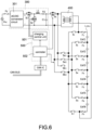
- FIG. 6 shows a detailed block circuit diagram of the battery cell balance circuit according to the preferred embodiment of the present disclosure.
- the AC/DC converter 300 includes an AC/DC conversion circuit 301 and a non-isolated DC/DC conversion.
- the non-isolated DC/DC conversion circuit is a step-down conversion circuit, which includes a switch S1, a switch S2, an inductor L1, a capacitor C1, and a resistor R1.
- the control unit 500 includes a charging control unit 501 and a controller 502 for controlling charging and discharging operations of the battery cells Cell 1-Cell 6.
- the battery cell balance circuit further includes a controller area network (CAN) involving a CAN IC and CAN bus. Therefore, the results of the detection and control of overall circuit by the control unit 500 are transmitted to the outside (external system) through the CAN so as to facilitate remote operators to acquire monitoring and control, thereby performing maintenance immediately to maintain the normal operation of the system.
- CAN controller area network
- FIG. 7 shows a flowchart of a method of operating the battery cell balance circuit according to the present disclosure.
- the battery cell balance circuit includes a plurality of battery cells connected in series to form a battery link, a plurality of switches, each of the switches correspondingly connected to each of the battery cells, and a circuit switch coupled between a DC power and the switches.
- the specific structure of the battery cell balance circuit may be found in the previous disclosure, and the detail description is omitted here for conciseness.
- the method of operating the battery cell balance circuit of the present disclosure includes steps of charging the battery cells (S11) and discharging the battery cells (S21).
Description
- The present disclosure relates to a battery cell balance circuit comprising a plurality of battery cells, and a plurality of switches, each of the switches correspondingly connected to each of the battery cells, an AC/DC converter, configured to receive an AC power and convert the AC power into a DC power, as known from
CN 113 078 714 A . The present disclosure further relates to a method of operating the same, and more particularly to an active battery cell balance circuit and a method of operating the same. Further such circuits and methods are known fromCN 110 752 635 A . - The statements in this section merely provide background information related to the present disclosure and do not necessarily constitute prior art.
- In the application of high-energy (high-power), high-voltage energy storage system, it is usually not operated by a single battery. In other words, in order to achieve high-energy (high-power) and high-voltage energy storage applications, the packaging of multiple battery cells will be modularized.
FIG. 1 shows a perspective diagram of a battery module having a plurality of battery cells in the related art. Eachbattery module 100 has 18 battery cells 101-10N arranged in two rows and connected in series. Therefore, in the application of the energy storage system, parallel connection can be provided through multiple groups ofbattery modules 100 at the same time so as to achieve high-energy (high-power) and high-voltage power supply applications. - For a single battery cell 101-10N, when the battery cell 101-10N ages, abnormal phenomena such as easy to be fully charged and easy to discharge will occur. For the
single battery module 100 shown inFIG. 1 , it has 18 battery cells 101-10N. Once one of the battery cells ages in advance, the effect of charging and discharging of the more seriously aged battery cell on the other 17 battery cells will lie in: during charging, the charging voltage of the more seriously aged battery cell rapidly rises. Therefore, for theoverall battery module 100, during the normal charging process, the more seriously aged battery cell may be over-charged (other battery cells may not be fully charged), or even damaged. Conversely, during discharging, the voltage of the more seriously aged battery cells rapidly drops. Therefore, for theoverall battery module 100, during the normal discharging process, the more seriously aged battery cell may be over-discharged (other battery cells may not be fully discharged), or even damaged. - An object of the present disclosure is to provide a battery cell balance circuit to solve the problems of existing technology.
- In order to achieve the above-mentioned object, the battery cell balance circuit comprises an isolated DC/DC converter, an input side of the isolated DC/DC converter coupled in parallel to an input side of each of the switches, and an output side of the isolated DC/DC converter coupled to the a battery link, wherein the plurality of battery cells are connected in series to form a battery link, a circuit switch, coupled between the AC/DC converter, the isolated DC/DC converter, and the plurality of switches, and a control unit, configured to provide a plurality of control signals to correspondingly control the plurality of switches and the circuit switch.
- Another object of the present disclosure is to provide a method of operating a battery cell balance circuit to solve the problems of existing technology.
- In order to achieve the above-mentioned object, the battery cell balance circuit includes a plurality of battery cells connected in series to form a battery link, a plurality of switches, each of the switches correspondingly connected to each of the battery cells, and a circuit switch coupled between a DC power and the switches. The method includes steps of: controlling the switch corresponding to the battery cell to be turned on when a battery voltage of any one of the battery cells is detected to be greater than an upper threshold voltage, releasing electrical energy of the battery cell to the battery link, controlling the circuit switch to be turned on and controlling the switch corresponding to the battery cell to be turned on when the battery voltage of any one of the battery cells is detected to be less than a lower threshold voltage, and receiving, by the battery cell, the electrical energy from the DC power.
- Advantageous embodiments are the subject of the dependent claims.
- Accordingly, the battery voltage is adjusted through the release and supplement of electrical energy for the more seriously aged battery cells, that is, when the battery voltage of the battery cell is too high, the electrical energy is transmitted to the battery link, and when the battery voltage of the battery cell is too low, the electrical energy is supplemented by the AC power. Therefore, the battery voltage of the more severely aged battery cells during the charging and discharging processes can be maintained to be approximately the same as the battery voltage of other battery cells so as to ensure the normal operation of the overall battery module. Accordingly, in the application of the energy storage system, the operation of the battery module can be continuously maintained without requiring frequent replacement of battery cells. Until the annual repair, the seriously aged battery cells will be replaced in order to improve the economic benefits of the application of the energy storage system.
- It is to be understood that both the foregoing general description and the following detailed description are exemplary, and are intended to provide further explanation of the present disclosure as claimed. Other advantages and features of the present disclosure will be apparent from the following description, drawings, and claims.
- The present disclosure can be more fully understood by reading the following detailed description of the embodiment, with reference made to the accompanying drawing as follows:
-
FIG. 1 is a perspective diagram of a battery module having a plurality of battery cells in the related art. -
FIG. 2 is a block circuit diagram of a switch unit of a battery cell balance circuit according to a first embodiment of the present disclosure. -
FIG. 3 is a block circuit diagram of the switch unit of the battery cell balance circuit according to a second embodiment of the present disclosure. -
FIG. 4 is a block circuit diagram of the switch unit of the battery cell balance circuit according to a third embodiment of the present disclosure. -
FIG. 5 is a block circuit diagram of the battery cell balance circuit according to a preferred embodiment of the present disclosure. -
FIG. 6 is a detailed block circuit diagram of the battery cell balance circuit according to the preferred embodiment of the present disclosure. -
FIG. 7 is a flowchart of a method of operating the battery cell balance circuit according to the present disclosure. - Reference will now be made to the drawing figures to describe the present disclosure in detail. It will be understood that the drawing figures and exemplified embodiments of present disclosure are not limited to the details thereof.
- Before describing the technical features of the battery cell balance circuit and the method of operating the same in detail, the passive battery cell balance technology and the active battery cell balance technology are briefly described. The passive battery cell balance technology refers to the energy consumption of battery cells with higher voltage through energy-consuming components. The common practice is: each battery cell is connected in parallel with resistance components through the switch circuit, and the energy of the battery cells with higher voltage is consumed by controlling the conduction (turned-on) of the switch and the parallel resistance components, thereby reducing the battery voltage of the battery cells to achieve a voltage balance between the battery cells.
- In comparison with the passive battery cell balance technology, the active battery cell balance technology refers to the redistribution of energy between cells. For example, using energy storage components (such as inductors or capacitors) to temporarily store the energy of the battery cells with higher voltage, and then release the temporarily stored energy to the battery cells with lower voltage to achieve the effect of voltage balance between the battery cells.
- However, in comparison with the existing active battery cell balance technology disclosed above, the present disclosure proposes different technical means to achieve the effect of active battery cell balance.
- Please refer to
FIG. 2 , which shows a block circuit diagram of a switch unit of a battery cell balance circuit according to a first embodiment of the present disclosure. InFIG. 2 , the battery cell balance circuit includes a plurality of (m) battery cells Cell 1-Cell m, and the battery cells Cell 1-Cell m are connected in series to form a battery link LCELL. In the configuration structure of this embodiment, since a positive end and a negative end of each battery cell Cell 1-Cell m are respectively connected to a switch unit, that is, a positive end of a firstbattery cell Cell 1 is connected to a switch unit S1A and a negative end of the firstbattery cell Cell 1 is connected to a switch unit S1B, and a positive end of a secondbattery cell Cell 2 is connected to a switch unit S2A and a negative end of the secondbattery cell Cell 2 is connected to a switch unit S2B, and so on, the number of switch units is twice the number of battery cells. For example, if the number of the battery cells Cell 1-Cell m is 18, the number of the switch units is 36. InFIG. 2 , the battery cells Cell 1-Cell m are connected to a charging-dischargingcircuit 200. In particular, positive ends of the battery cells Cell 1-Cell m are respectively connected to positive supplying ends or positive receiving ends of the charging-discharging circuit 200 through the switch units S1A-SmA. Similarly, negative ends of the battery cells Cell 1-Cell m are respectively connected to negative supplying ends or negative receiving ends of the charging-discharging circuit 200 through the switch units S1B-SmB. - Incidentally, the charging-
discharging circuit 200 shown inFIG. 2 is used to provide a charging operation when a voltage of the battery cells Cell 1-Cell m (at least one of them) is too low to be charged, or a discharging operation when the voltage is too high to be discharged. That is, the charging-dischargingcircuit 200 may be, for example, but not limited to, a circuit having both charging and discharging functions, or two sets of circuits with separate charging and discharging functions. - Please refer to
FIG. 3 , which shows a block circuit diagram of the switch unit of the battery cell balance circuit according to a second embodiment of the present disclosure. InFIG. 3 , the battery cell balance circuit includes a plurality of (m) battery cells Cell 1-Cell m, and the battery cells Cell 1-Cell m are connected in series to form a battery link LCELL. In the configuration structure of this embodiment, since a positive end of the firstbattery cell Cell 1 is connected to a switch unit S1, a negative end of the last battery cell Cell m is connected to a switch unit Sm+1, and the positive end and the negative end of the middle (the remaining)battery cells Cell 2 to Cell m-1 jointly connected to a switch unit S2-Sm. Furthermore, a switch assembly Sa composed of four switch units (described in detail later), the charging and discharging operations of the battery cells Cell 1-Cell m are realized. Therefore, the number of the switch units is five more than the number of the battery cells. For example, if the number of the battery cells Cell 1-Cell m is 18, the number of the switch units is 23. - Please refer to
FIG. 4 , which shows a block circuit diagram of the switch unit of the battery cell balance circuit according to a third embodiment of the present disclosure. Compared with the previous embodiments ofFIG. 2 and FIG. 3 , the switch units shown inFIG. 4 are realized by electromagnetic relays RL1-RL6 (take the battery link LCELL with 6 battery cells as an example). In other words, the excitation control of the electromagnetic relays RL1-RL6 is used so that the effect of turning on and turning off is implemented, and a path for charging and discharging operations of the battery cells Cell 1-Cell 6 is provided. - Specifically, take the embodiment of
FIG. 4 as an example, the battery cell balance circuit mainly includes an AC/DC converter 300, a plurality of battery cells Cell 1-Cell 6, a plurality of switch units RL1-RL6, an isolated DC/DC converter 400, acontrol unit 500. The AC/DC converter 300 receives an AC power VAC, and converts the AC power VAC into a DC power. The battery cells Cell 1-Cell 6 are connected in series to form a battery link LCELL. Each of the switch units RL1-RL6 is correspondingly connected to each of the battery cells Cell 1-Cell 6. In the embodiment shown inFIG. 4 , each switch unit RL1 - RL6 is an electromagnetic relay, which uses the principle of electromagnetic effect to excite the coil to change states of the contact to implement the turned-on and the turned-off function. Moreover, the number of switch units RL1-RL6 is the same as that of battery cells Cell 1-Cell 6, that is, the firstbattery cell Cell 1 is connected to the first switch unit RL1, the secondbattery cell Cell 2 is connected to the second switch unit RL2, and so on. - An input side of the isolated DC/
DC converter 400 is coupled in parallel to an input side of each of the switches RL1-RL6. Specifically, the input side of the isolated DC/DC converter 400 has a positive end and a negative end, and the positive end is connected to a positive end of the DC power converted from the AC/DC converter 300 and the negative end is connected to a negative end of the DC power. Each electromagnetic relay has a first side and a second side, and the first side and the second side have a positive end and a negative end, respectively. The positive end of the first side is coupled to the positive end of the DC power and the positive end of the input side of the isolated DC/DC converter 400, the negative end of the first side is coupled to the negative end of the DC power and the negative end of the input side of the isolated DC/DC converter 400, and the positive end and the negative end of the second side are correspondingly connected to the positive ends and the negative ends of the battery cells, respectively. In other words, the positive ends of the first sides of all the electromagnetic relays are jointly coupled, and then coupled to the positive end of the DC power and the positive end of the input side of the isolated DC/DC converter 400. Similarly, the negative ends of the first sides of all the electromagnetic relays are jointly coupled, and then coupled to the negative end of the DC power and the negative end of the input side of the isolated DC/DC converter 400. - Moreover, an output side of the isolated DC/
DC converter 400 is coupled in series to the battery link LCELL. The output side of the isolated DC/DC converter 400 has a positive end and a negative end, and the positive end is coupled to a positive end of the battery link LCELL (i.e., a positive end of the first battery cell Cell 1) and the negative end is coupled to a negative end of the battery link LCELL (i.e., a negative end of the sixth battery cell Cell 6) so that the output side of the isolated DC/DC converter 400 is coupled in series to the battery link LCELL. - The circuit switch Sc is coupled between the AC/
DC converter 300 and the isolated DC/DC converter 400, that is, between the AC/DC converter 300 and the switch units RL1-RL6. In one embodiment, the circuit switch Sc may be, for example, but not limited to, an electromagnetic relay or a transistor switch, such as a MOSFET. - During the charging process of the plurality of battery cells Cell 1-
Cell 6, if all battery cells Cell 1-Cell 6 are normal, the battery voltages of all battery cells Cell 1-Cell 6 will not be abnormally high when fully charged. Similarly, during the discharging process of the plurality of battery cells Cell 1-Cell 6, if all battery cells Cell 1-Cell 6 are normal, the battery voltages of all battery cells Cell 1-Cell 6 will not be abnormally low when fully discharged. - Once the battery voltage of any one of the battery cells Cell 1-
Cell 6 is too high (abnormally high) during the charging process, the electrical energy of the battery cell with the too-high battery voltage is released to the battery link LCELL so that battery voltage of the battery cell is reduced and the battery cell is not over charged. In addition, once the battery voltage of any one of the battery cells Cell 1-Cell 6 is too low (abnormally low) during the discharging process, the AC power VAC provides electrical energy to the battery cell with the too-low battery voltage so that the battery voltage of the battery cell is increased and the battery cell is not over discharged. - Specifically, during the charging process of the battery cells Cell 1-
Cell 6, when thecontrol unit 500 detects that a battery voltage of any one of the battery cells Cell 1-Cell 6 is greater than the upper threshold voltage, thecontrol unit 500 provides switch control signals SRL1-SRL6 to turn on the switch unit RL1-RL6 corresponding to the battery cell with the too-high battery voltage so that the electrical energy of the battery cell Cell 1-Cell 6 with the too-high battery voltage is released to the battery link LCELL through the isolated DC/DC converter 400. For example, when thecontrol unit 500 detects that the battery voltage of the firstbattery cell Cell 1 is too high (i.e., the battery voltage is greater than the upper threshold voltage), thecontrol unit 500 turns on the first switch unit RL1 by the first switch control signal SRL1 so that the electrical energy of the first battery cell is released to the battery link LCELL through the first switch unit RL1 and the isolated DC/DC converter 400. In addition to reducing the battery voltage of the firstbattery cell Cell 1 to prevent over-charging, the electrical energy of the firstbattery cell Cell 1 can also be used as the electrical energy for charging the battery link LCELL without wasting. Similarly, the operation principles of other battery cells are the same as those described above, and the detail description is omitted here for conciseness. - During the discharging process of the battery cells Cell 1-
Cell 6, when thecontrol unit 500 detects that a battery voltage of any one of the battery cells Cell 1-Cell 6 is less than the lower threshold voltage, thecontrol unit 500 provides a switch control signal Sec to turn on the circuit switch Sc, and provides switch control signals SRL1-SRL6 to turn on the switch unit RL1-RL6 corresponding to the battery cell with the too-low battery voltage so that the battery cell Cell 1-Cell 6 with the too-low battery voltage receives electrical energy provided from the AC power VAC. In particular, the lower threshold voltage is less than the upper threshold voltage. For example, when thecontrol unit 500 detects that the battery voltage of the firstbattery cell Cell 1 is too low (i.e., the battery voltage is less than the lower threshold voltage), thecontrol unit 500 turns on the circuit switch Sc by the switch control signal Scc, and turns on the first switch unit RL1 by the first switch control signal SRL1 so that the AC power VAC supplies power to the first battery cell Cell 1 (i.e., provides the electrical energy to the first battery cell Cell 1) through the circuit switch Sc and the first switch unit RL1, thereby increasing the battery voltage of the firstbattery cell Cell 1 to prevent over-discharging. Similarly, the operation principles of other battery cells are the same as those described above, and the detail description is omitted here for conciseness. - Accordingly, the battery voltage is adjusted through the release and supplement of electrical energy for the more seriously aged battery cells, that is, when the battery voltage of the battery cell is too high, the electrical energy is transmitted to the battery link, and when the battery voltage of the battery cell is too low, the electrical energy is supplemented by the AC power. Therefore, the battery voltage of the more severely aged battery cells during the charging and discharging processes can be maintained to be approximately the same as the battery voltage of other battery cells so as to ensure the normal operation of the overall battery module. Accordingly, in the application of the energy storage system, the operation of the battery module can be continuously maintained without requiring frequent replacement of battery cells. Until the annual repair, the seriously aged battery cells will be replaced in order to improve the economic benefits of the application of the energy storage system.
- Please refer to
FIG. 4 again, the battery cell balance circuit further includes a plurality of over-current protection components correspondingly coupled to the battery cells Cell 1-Cell 6. In one embodiment, the over-current protection components are fuses F1-F7. During the charging and discharging process, if an overcurrent abnormality occurs, an overcurrent protection can be provided through the corresponding fuses F1-F7 to protect the battery cells Cell 1-Cell 6. - Please refer to
FIG. 5 , which shows a block circuit diagram of the battery cell balance circuit according to a preferred embodiment of the present disclosure, and theFIG. 5 is cooperated with the embodiment shown inFIG. 3 (i.e., the second embodiment of the switch unit). Take the battery link LCELL with 6 battery cells as an example, the battery cell balance circuit mainly includes an AC/DC converter 300, an isolated DC/DC converter 400, acontrol unit 500, a plurality of (6) battery cells Cell 1-Cell 6 (connected in series to form a battery link LCELL), a plurality of (7) switch units S1-S7, and a switch assembly Sa having a plurality of switch units Sa1, Sa2, Sb1, Sb2. Thecontrol unit 500 provides switch control signals S1c-S7c to correspondingly control the switch units S1-S7, provides switching switch control signals Salc-Sb2c to correspondingly control the switch units Sa1, Sa2, Sb1, Sb2, and provides a switch control signal SCC to control the circuit switch SC. In this embodiment, due to the configuration design (connection relationship) of the switch units S1-S7, for a battery module with more battery cells, the number of switch units may be significantly reduced (as described inFIG. 3 above). Therefore, with the turning on and turning off the switch units Sa1, Sa2, Sb1, Sb2, a path for providing the charging and discharging operations of the battery cells Cell 1-Cell 6 can be implemented. - Specifically, during the charging process of the battery cells Cell 1-
Cell 6, when thecontrol unit 500 detects that a battery voltage of any one of the battery cells Cell 1-Cell 6 is greater than the upper threshold voltage, thecontrol unit 500 provides switch control signals S1c-S7c toturn on the switch unit S1-S7 corresponding to the battery cell with the too-high battery voltage so that the electrical energy of the battery cell Cell 1-Cell 6 with the too-high battery voltage is released to the battery link LCELL through the isolated DC/DC converter 400. For example, when thecontrol unit 500 detects that the battery voltage of the firstbattery cell Cell 1 is too high (i.e., the battery voltage is greater than the upper threshold voltage), thecontrol unit 500 turns on the first switching switch unit Sa1 by the first switching switch control signal Sa1c, turns on the second switching switch unit Sa2 by the second switching switch control signals Sa2c, turns on the first switch unit S1 by the first switch control signal S1c, and turns on the second switch unit S2 by the second switch control signal S2c so that the electrical energy of the first battery cell is released to the battery link LCELL through the first switch unit S1, the second switch unit S2, the first switching switch unit Sa1, the second switching switch unit Sa2, and the isolated DC/DC converter 400. In addition to reducing the battery voltage of the firstbattery cell Cell 1 to prevent over-charging, the electrical energy of the firstbattery cell Cell 1 can also be used as the electrical energy for charging the battery link LCELL without wasting. - For example, when the
control unit 500 detects that the battery voltage of the secondbattery cell Cell 2 is too high (i.e., the battery voltage is greater than the upper threshold voltage), thecontrol unit 500 turns on the third switching switch unit Sb1 by the third switching switch control signal Sb1c, turns on the fourth switching switch unit Sb2 by the fourth switching switch control signals Sb2c, turns on the second switch unit S2 by the second switch control signal S2c, and turns on the third switch unit S3 by the third switch control signal S3c so that the electrical energy of the second battery cell is released to the battery link LCELL through the second switch unit S2, the third switch unit S3, the third switching switch unit Sb1, the fourth switching switch unit Sb2, and the isolated DC/DC converter 400. In addition to reducing the battery voltage of the secondbattery cell Cell 2 to prevent over-charging, the electrical energy of the secondbattery cell Cell 2 can also be used as the electrical energy for charging the battery link LCELL without wasting. - During the discharging process of the battery cells Cell 1-Cell 6, when the control unit 500 detects that a battery voltage of any one of the battery cells Cell 1-Cell 6 is less than the lower threshold voltage, the control unit 500 provides a switch control signal SCC to turn on the circuit switch SC, and provides switch control signals S1c-S7c to turn on the switch unit S1-S7 corresponding to the battery cell with the too-low battery voltage so that the battery cell Cell 1-Cell 6 with the too-low battery voltage receives electrical energy provided from the AC power VAC. For example, when the control unit 500 detects that the battery voltage of the first battery cell Cell 1 is too low (i.e., the battery voltage is less than the lower threshold voltage), the control unit 500 turns on the circuit switch Sc by the switch control signal Scc, turns on the first switching switch unit Sa1 by the first switching switch control signal Sa1c, turns on the second switching switch unit Sa2 by the second switching switch control signal Sa2c, turns on the first switch unit S1 by the first switch control signal S1c, and turns on the second switch unit S2 by the second switch control signal S2c so that the AC power VAC supplies power to the first battery cell Cell 1 (i.e., provides the electrical energy to the first battery cell Cell 1) through the circuit switch SC, the first switching switch unit Sa1, the second switching switch unit Sa2, the first switch unit S1, and the second switch unit S2, thereby increasing the battery voltage of the first battery cell Cell 1 to prevent over-discharging.
- For example, when the
control unit 500 detects that the battery voltage of the secondbattery cell Cell 2 is too low (i.e., the battery voltage is less than the lower threshold voltage), thecontrol unit 500 turns on the circuit switch Sc by the switch control signal SCC, turns on the third switching switch unit Sb1 by the third switching switch control signal Sb1c, turns on the fourth switching switch unit Sb2 by the fourth switching switch control signal Sb2c, turns on the second switch unit S2 by the second switch control signal S2c, and turns on the third switch unit S3 by the third switch control signal S3c so that the AC power VAC supplies power to the second battery cell Cell 2 (i.e., provides the electrical energy to the second battery cell Cell 2) through the circuit switch SC, the third switching switch unit Sb1, the fourth switching switch unit Sb2, the second switch unit S2, and the third switch unit S3, thereby increasing the battery voltage of the secondbattery cell Cell 2 to prevent over-discharging. - Accordingly, the control principle of the switch assembly Sa (including switching switch units Sa1,Sa2,Sb1,Sb2) and the switch units S1-S7 of the battery cell balance circuit shown in
FIG. 5 is: according to the positive end and the negative end of the DC power converted and outputted by the AC/DC converter 300, the positive end and the negative end of the battery cells Cell 1-Cell 6 with the too-high battery voltage (or too-low battery voltage) are consistent so as to implement the adjustment of the battery voltage through the energy release and energy replenishment for the seriously aged battery cells. - Similarly, the first embodiment of the switch unit shown in
FIG. 2 may also be applied to the structure ofFIG. 5 , and the control principle of the switch unit is similar to that ofFIG. 5 , and the detail description is omitted here for conciseness. - Please refer to
FIG. 6 , which shows a detailed block circuit diagram of the battery cell balance circuit according to the preferred embodiment of the present disclosure. TheFIG. 6 more specifically discloses that the AC/DC converter 300 includes an AC/DC conversion circuit 301 and a non-isolated DC/DC conversion. In this embodiment, the non-isolated DC/DC conversion circuit is a step-down conversion circuit, which includes a switch S1, a switch S2, an inductor L1, a capacitor C1, and a resistor R1. Thecontrol unit 500 includes a chargingcontrol unit 501 and acontroller 502 for controlling charging and discharging operations of the battery cells Cell 1-Cell 6. Moreover, the battery cell balance circuit further includes a controller area network (CAN) involving a CAN IC and CAN bus. Therefore, the results of the detection and control of overall circuit by thecontrol unit 500 are transmitted to the outside (external system) through the CAN so as to facilitate remote operators to acquire monitoring and control, thereby performing maintenance immediately to maintain the normal operation of the system. - Please refer to
FIG. 7 , which shows a flowchart of a method of operating the battery cell balance circuit according to the present disclosure. The battery cell balance circuit includes a plurality of battery cells connected in series to form a battery link, a plurality of switches, each of the switches correspondingly connected to each of the battery cells, and a circuit switch coupled between a DC power and the switches. The specific structure of the battery cell balance circuit may be found in the previous disclosure, and the detail description is omitted here for conciseness. The method of operating the battery cell balance circuit of the present disclosure includes steps of charging the battery cells (S11) and discharging the battery cells (S21). When a battery voltage of any one of the battery cells is detected to be greater than an upper threshold voltage during the charging of the battery cells, controlling the switch corresponding to the battery cell to be turned on (S12). Furthermore, releasing electrical energy of the battery cell to the battery link (S13). When a battery voltage of any one of the battery cells is detected to be less than a lower threshold voltage during the discharging of the battery cells, controlling the circuit switch to be turned on, and controlling the switch corresponding to the battery cell to be turned on (S22). Moreover, the battery cell receives the electrical energy provided from the AC power (S23). - In summary, the advantages and features of the present disclosure are:
- 1. The battery cell balance circuit of the present disclosure adjusts the battery voltage through the release and supplement of electrical energy for the more seriously aged battery cells. That is, when the battery voltage of the battery cell is too high, the electrical energy is transmitted to the battery link, and when the battery voltage of the battery cell is too low, the electrical energy is supplemented by the AC power. Therefore, the battery voltage of the more severely aged battery cells during the charging and discharging processes can be maintained to be approximately the same as the battery voltage of other battery cells so as to ensure the normal operation of the overall battery module. Accordingly, in the application of the energy storage system, the operation of the battery module can be continuously maintained without requiring frequent replacement of battery cells. Until the annual repair, the seriously aged battery cells will be replaced in order to improve the economic benefits of the application of the energy storage system.
- 2. The selected battery modules are coupled to the battery cell balance circuit through solid state switches. In such circuit configuration, switches can use solid state switches instead of double pole single throw switches (traditional solenoid valve switches), thereby increasing switch life in battery cell balance circuit and optimizing voltage differences between battery modules.
- 3. For battery link charging: select the battery cell with the highest battery voltage, recover its energy, and feed it back to the battery link to extend the charging time of the battery link.
- 4. For battery link discharging: select the battery cell with the lowest battery voltage, and charge it from the AC power to extended the discharging time of the battery link.
Claims (15)
- A battery cell balance circuit, comprisinga plurality of battery cells (Cell 1-Cell m, Cell 1-Cell 6),a plurality of switches (S1A-SmB, S1-Sm+1, RL1-RL6), each of the switches (S1A-SmB, S1-Sm+1, RL1-RL6) correspondingly connected to each of the battery cells (Cell 1-Cell m, Cell 1-Cell 6), andan AC/DC converter (300), configured to receive an AC power (VAC) and convert the AC power (VAC) into a DC power,characterized in that the battery cell balance circuit further comprises:an isolated DC/DC converter (400), an input side of the isolated DC/DC converter (400) coupled in parallel to an input side of each of the switches (S1A-SmB, S1-Sm+1, RL1-RL6), and an output side of the isolated DC/DC converter (400) coupled to a battery link (LCELL), wherein the plurality of battery cells (Cell 1-Cell m, Cell 1-Cell 6) are connected in series to form a battery link (LCELL),a circuit switch (SC), coupled between the AC/DC converter (300), the isolated DC/DC converter (400), and the plurality of switches (S1A-SmB, S1-Sm+1, RL1-RL6), anda control unit (500), configured to provide a plurality of control signals (SRL1-SRL6, S1c-S7c, SCC) to correspondingly control the plurality of switches (S1A-SmB, S1-Sm+1, RL1-RL6) and the circuit switch (SC).
- The battery cell balance circuit as claimed in claim 1, wherein when the control unit (500) detects a battery voltage of any one of the battery cells (Cell 1-Cell m, Cell 1-Cell 6) is greater than an upper threshold voltage, the control unit (500) turns on the switch (S1A-SmB, S1-Sm+1, RL1-RL6) corresponding to the battery cell so that electrical energy of the battery cell (Cell 1-Cell m, Cell 1-Cell 6) is released to the battery link (LCELL) through the isolated DC/DC converter (400).
- The battery cell balance circuit as claimed in claim 1, wherein when the control unit (500) detects that a battery voltage of any one of the battery cells (Cell 1-Cell m, Cell 1-Cell 6) is less than a lower threshold voltage, the control unit (500) turns on the circuit switch (SC) and turns on the switch (S1A-SmB, S1-Sm+1, RL1-RL6) corresponding to the battery cell (Cell 1-Cell m, Cell 1-Cell 6) so that the battery cell receives the electrical energy from the AC power (VAC).
- The battery cell balance circuit as claimed in claim 1, wherein the switches (RL1-RL6) are electromagnetic relays (RL1-RL6),a first positive end of each of the switches (RL1-RL6) connected to a positive end of the DC power, and a first negative end of each of the switches (RL1-RL6) connected to a negative end of the DC power,a second positive end of each of the switches (RL1-RL6) correspondingly connected to a positive end of the battery cell (Cell 1-Cell m, Cell 1-Cell 6), and a second negative end of the switches (RL1-RL6) correspondingly connected to a negative end of the battery cell (Cell 1-Cell m, Cell 1-Cell 6).
- The battery cell balance circuit as claimed in claim 1, wherein the switches (S1A-SmB) comprise a plurality of switch units (S1A-SmB),the positive end of each of the battery cells (Cell 1-Cell m, Cell 1-Cell 6) respectively connected to a first end of one switch unit (S1A-SmB), and second ends of the switch units (S1A-SmB) jointly connected to a positive end of the DC power,the negative end of each of the battery cells (Cell 1-Cell m, Cell 1-Cell 6) respectively connected to a first end of one switch unit (S1A-SmB), and second ends of the switch units (S1A-SmB) jointly connected to a negative end of the DC power.
- The battery cell balance circuit as claimed in claim 1, wherein the switches (S1-Sm+1, Sa, Sa1-Sb2) comprise a plurality of switch units (S1-Sm+1) and a switch assembly (Sa, Sa1-Sb2),a positive end of a first battery cell of the battery cells (Cell 1-Cell m, Cell 1-Cell 6) connected to a first end of one switch unit (S1-Sm+1), a negative end of a last battery cell of the battery cells (Cell 1-Cell m, Cell 1-Cell 6) connected to a first end of one switch unit (S1-Sm+1), and the positive end and the negative end of the middle battery cells (Cell 1-Cell m, Cell 1-Cell 6) jointly connected to a first end of one switch unit (S1-Sm+1),the switch assembly (Sa, Sa1-Sb2) comprises a plurality of switching switch units (Sa1-Sb2),wherein second ends of the switch units (S1-Sm+1) are correspondingly connected to the switching switch units (Sa1-Sb2) so that the positive ends of the battery cells (Cell 1-Cell m, Cell 1-Cell 6) are correspondingly connected to a positive end of the DC power and the negative ends of the battery cells (Cell 1-Cell m, Cell 1-Cell 6) are correspondingly connected to a negative end of the DC power.
- The battery cell balance circuit as claimed in claim 1, wherein the AC/DC converter (300) comprises an AC/DC conversion circuit and a non-isolated DC/DC conversion circuit; the non-isolated DC/DC conversion circuit is a buck conversion circuit comprising two switches (S1, S2) and one inductor (L1).
- The battery cell balance circuit as claimed in claim 1, wherein the control unit (500) comprises a battery charge control unit (500) and a controller configured to control charging and discharging operations of the battery cells (Cell 1-Cell m, Cell 1-Cell 6).
- The battery cell balance circuit as claimed in claim 1, further comprising:
a plurality of over-current protection components (F1-F7) correspondingly connected between the switches and the battery cells (Cell 1-Cell m, Cell 1-Cell 6). - A method of operating a battery cell balance circuit, the battery cell balance circuit comprising a plurality of battery cells (Cell 1-Cell m, Cell 1-Cell 6) connected in series to form a battery link (LCELL), a plurality of switches (S1A-SmB, S1-Sm+1, RL1-RL6), each of the switches (S1A-SmB, S1-Sm+1, RL1-RL6) correspondingly connected to each of the battery cells (Cell 1-Cell m, Cell 1-Cell 6), and a circuit switch (SC) coupled between a DC power and the switches (S1A-SmB, S1-Sm+1, RL1-RL6), characterized in that the method comprises steps of:controlling the switch (S1A-SmB, S1-Sm+1, RL1-RL6) corresponding to the battery cell (Cell 1-Cell m, Cell 1-Cell 6) to be turned on when a battery voltage of any one of the battery cells (Cell 1-Cell m, Cell 1-Cell 6) is detected to be greater than an upper threshold voltage,releasing electrical energy of the battery cell (Cell 1-Cell m, Cell 1-Cell 6) to the battery link (LCELL),controlling the circuit switch (SC) to be turned on and controlling the switch (S1A-SmB, S1-Sm+1, RL1-RL6) corresponding to the battery cell (Cell 1-Cell m, Cell 1-Cell 6) to be turned on when the battery voltage of any one of the battery cells (Cell 1-Cell m, Cell 1-Cell 6) is detected to be less than a lower threshold voltage, andreceiving, by the battery cell (Cell 1-Cell m, Cell 1-Cell 6), the electrical energy from the DC power.
- The method of operating the battery cell balance circuit as claimed in claim 10, wherein the battery cell balance circuit further comprises:an isolated DC/DC converter (400), an input side of the isolated DC/DC converter (400) coupled in parallel to an input side of each of the switches (S1A-SmB, S1-Sm+1, RL1-RL6), and an output side of the isolated DC/DC converter (400) coupled to the battery link (LCELL),wherein the electrical energy of the battery cell (Cell 1-Cell m, Cell 1-Cell 6) is released to the battery link (LCELL) through the isolated DC/DC converter (400).
- The method of operating the battery cell balance circuit as claimed in claim 10, wherein the battery cell balance circuit further comprises:an AC/DC converter (300), configured to receive an AC power (VAC) and convert the AC power (VAC) into the DC power,wherein the circuit switch (SC) is coupled to the AC power (VAC) through the AC/DC converter (300).
- The method of operating the battery cell balance circuit as claimed in claim 10, wherein the switches (RL1-RL6) are electromagnetic relays (RL1-RL6),a first positive end of each of the switches (RL1-RL6) connected to a positive end of the DC power, and a first negative end of each of the switches (RL1-RL6) connected to a negative end of the DC power,a second positive end of each of the switches (RL1-RL6) correspondingly connected to a positive end of the battery cell (Cell 1-Cell m, Cell 1-Cell 6), and a second negative end of the switches (RL1-RL6) correspondingly connected to a negative end of the battery cell (Cell 1-Cell m, Cell 1-Cell 6).
- The method of operating the battery cell balance circuit as claimed in claim 10, wherein the switches (S1A-SmB) comprise a plurality of switch units (S1A-SmB),the positive end of each of the battery cells (Cell 1-Cell m, Cell 1-Cell 6) respectively connected to a first end of one switch unit (S1A-SmB), and second ends of the switch units (S1A-SmB) jointly connected to a positive end of the DC power,the negative end of each of the battery cells (Cell 1-Cell m, Cell 1-Cell 6) respectively connected to a first end of one switch unit (S1A-SmB), and second ends of the switch units (S1A-SmB) jointly connected to a negative end of the DC power.
- The method of operating the battery cell balance circuit as claimed in claim 10, wherein the switches (S1-Sm+1, Sa1-Sb2) comprise a plurality of switch units (S1-Sm+1) and a switch assembly (Sa, Sa1-Sb2),a positive end of a first battery cell of the battery cells (Cell 1-Cell m, Cell 1-Cell 6) connected to a first end of one switch unit (S1-Sm+1), a negative end of a last battery cell of the battery cells (Cell 1-Cell m, Cell 1-Cell 6) connected to a first end of one switch unit (S1-Sm+1), and the positive end and the negative end of the middle battery cells (Cell 1-Cell m, Cell 1-Cell 6) jointly connected to a first end of one switch unit (S1-Sm+1),the switch assembly (Sa, Sa1-Sb2) comprises a plurality of switching switch units (Sa, Sa1-Sb2),wherein second ends of the switch units (S1-Sm+1) are correspondingly connected to the switching switch units (Sa, Sa1-Sb2) so that the positive ends of the battery cells (Cell 1-Cell m, Cell 1-Cell 6) are correspondingly connected to a positive end of the DC power and the negative ends of the battery cells (Cell 1-Cell m, Cell 1-Cell 6) are correspondingly connected to a negative end of the DC power.
Applications Claiming Priority (2)
| Application Number | Priority Date | Filing Date | Title |
|---|---|---|---|
| US202163232925P | 2021-08-13 | 2021-08-13 | |
| CN202111579357.6A CN115706438A (en) | 2021-08-13 | 2021-12-22 | Battery balancing circuit and operation method thereof |
Publications (2)
| Publication Number | Publication Date |
|---|---|
| EP4135153A1 EP4135153A1 (en) | 2023-02-15 |
| EP4135153B1 true EP4135153B1 (en) | 2024-03-27 |
Family
ID=81851033
Family Applications (1)
| Application Number | Title | Priority Date | Filing Date |
|---|---|---|---|
| EP22175813.9A Active EP4135153B1 (en) | 2021-08-13 | 2022-05-27 | Battery cell balance circuit and method of operating the same |
Country Status (3)
| Country | Link |
|---|---|
| US (1) | US20230048191A1 (en) |
| EP (1) | EP4135153B1 (en) |
| JP (1) | JP7427051B2 (en) |
Family Cites Families (14)
| Publication number | Priority date | Publication date | Assignee | Title |
|---|---|---|---|---|
| US8294421B2 (en) | 2008-09-05 | 2012-10-23 | O2Micro Inc | Cell balancing systems employing transformers |
| JP5567684B2 (en) | 2009-12-14 | 2014-08-06 | リーチ インターナショナル コーポレイション | Battery balancing circuit and method for balancing energy stored in a plurality of cells of a battery having a first terminal and a second terminal |
| JP5641006B2 (en) * | 2011-08-31 | 2014-12-17 | ソニー株式会社 | Power storage device |
| US9172259B2 (en) | 2012-11-29 | 2015-10-27 | Samsung Sdi Co., Ltd. | Apparatus for managing battery, and energy storage system |
| DE102013106872A1 (en) | 2013-07-01 | 2015-01-08 | H-Tech Ag | Device and method for charge equalization of an energy storage device |
| CN105375539B (en) | 2014-08-21 | 2021-02-09 | 上海稳得新能源科技有限公司 | Automatic balance charger for power battery |
| TWI581543B (en) | 2014-10-03 | 2017-05-01 | 輝創電子股份有限公司 | Active balancing module for a series battery and control method thereof |
| JP2017063520A (en) | 2015-09-24 | 2017-03-30 | アイシン精機株式会社 | Power storage device |
| US10063070B2 (en) | 2016-11-25 | 2018-08-28 | National Chung Shan Institute Of Science And Technology | Battery active balancing system |
| TWI666851B (en) | 2018-05-04 | 2019-07-21 | 大陸商東莞市高效電控有限公司 | Optimized battery balance system and operation method thereof |
| US10615610B1 (en) | 2019-05-28 | 2020-04-07 | Ekergy Llc | System and method for efficient charging of multiple battery cassettes |
| CN110752635A (en) * | 2019-10-12 | 2020-02-04 | 山东大学 | Online capacity monitoring and charging and discharging dual-state equalization circuit and method for series battery pack |
| CN111976538B (en) | 2019-12-27 | 2022-09-20 | 中北大学 | Equalizing structure and equalizing method of vehicle-mounted composite power supply system |
| CN113078714B (en) | 2021-04-12 | 2023-09-22 | 华为数字能源技术有限公司 | Energy storage system and control method thereof |
-
2022
- 2022-05-23 US US17/751,414 patent/US20230048191A1/en active Pending
- 2022-05-24 JP JP2022084551A patent/JP7427051B2/en active Active
- 2022-05-27 EP EP22175813.9A patent/EP4135153B1/en active Active
Also Published As
| Publication number | Publication date |
|---|---|
| JP7427051B2 (en) | 2024-02-02 |
| US20230048191A1 (en) | 2023-02-16 |
| EP4135153A1 (en) | 2023-02-15 |
| JP2023026313A (en) | 2023-02-24 |
Similar Documents
| Publication | Publication Date | Title |
|---|---|---|
| KR102084926B1 (en) | Battery system and method for providing an intermediate voltage | |
| US8129952B2 (en) | Battery systems and operational methods | |
| EP2384530B1 (en) | Charge equalization apparatus for series-connected battery string using regulated voltage source | |
| KR101188944B1 (en) | Charge equalization apparatus with parallel connection of secondary windings of multiple transformers | |
| KR101772975B1 (en) | Battery module with cell balancing function and Battery System having that battery module | |
| US8269455B2 (en) | Charge balancing system | |
| US20120286733A1 (en) | Battery system and battery equalizer | |
| US9099870B2 (en) | Charge redistribution method for cell arrays | |
| CN111106750B (en) | Uninterrupted power source and battery pack voltage-boosting circuit thereof | |
| JP5596521B2 (en) | DC power supply system and bidirectional power converter | |
| CN216056382U (en) | Battery energy storage system | |
| JP2009148110A (en) | Charger/discharger and power supply device using the same | |
| KR101969301B1 (en) | Apparatus for controlling charging and discharging of batterry for dc grid | |
| EP4135153B1 (en) | Battery cell balance circuit and method of operating the same | |
| JP2017127173A (en) | Power storage device | |
| CN103855768A (en) | Storage battery non-floating-charging hot standby technology | |
| TWI792793B (en) | Battery cell balance circuit and method of operating the same | |
| Karnjanapiboon et al. | The high efficiency charge equalized system for serially connected VRLA battery string using synchronous flyback converter | |
| CN113708442A (en) | Bypass type battery equalization device and control method | |
| KR20230160873A (en) | Energy storage system, method for controlling energy storage system, and solar power generation system | |
| CN112736999A (en) | Series battery equalization device with multiple flyback converters | |
| JP2009171724A (en) | Bidirectional converter | |
| CN110661315A (en) | Active equalization device and method for energy storage power station battery | |
| WO2021241136A1 (en) | Backup power supply device | |
| JP2023026313A5 (en) |
Legal Events
| Date | Code | Title | Description |
|---|---|---|---|
| PUAI | Public reference made under article 153(3) epc to a published international application that has entered the european phase |
Free format text: ORIGINAL CODE: 0009012 |
|
| STAA | Information on the status of an ep patent application or granted ep patent |
Free format text: STATUS: THE APPLICATION HAS BEEN PUBLISHED |
|
| AK | Designated contracting states |
Kind code of ref document: A1 Designated state(s): AL AT BE BG CH CY CZ DE DK EE ES FI FR GB GR HR HU IE IS IT LI LT LU LV MC MK MT NL NO PL PT RO RS SE SI SK SM TR |
|
| STAA | Information on the status of an ep patent application or granted ep patent |
Free format text: STATUS: REQUEST FOR EXAMINATION WAS MADE |
|
| 17P | Request for examination filed |
Effective date: 20230606 |
|
| RBV | Designated contracting states (corrected) |
Designated state(s): AL AT BE BG CH CY CZ DE DK EE ES FI FR GB GR HR HU IE IS IT LI LT LU LV MC MK MT NL NO PL PT RO RS SE SI SK SM TR |
|
| GRAP | Despatch of communication of intention to grant a patent |
Free format text: ORIGINAL CODE: EPIDOSNIGR1 |
|
| STAA | Information on the status of an ep patent application or granted ep patent |
Free format text: STATUS: GRANT OF PATENT IS INTENDED |
|
| INTG | Intention to grant announced |
Effective date: 20231031 |
|
| GRAS | Grant fee paid |
Free format text: ORIGINAL CODE: EPIDOSNIGR3 |
|
| GRAA | (expected) grant |
Free format text: ORIGINAL CODE: 0009210 |
|
| STAA | Information on the status of an ep patent application or granted ep patent |
Free format text: STATUS: THE PATENT HAS BEEN GRANTED |
|
| AK | Designated contracting states |
Kind code of ref document: B1 Designated state(s): AL AT BE BG CH CY CZ DE DK EE ES FI FR GB GR HR HU IE IS IT LI LT LU LV MC MK MT NL NO PL PT RO RS SE SI SK SM TR |
|
| REG | Reference to a national code |
Ref country code: GB Ref legal event code: FG4D |
|
| REG | Reference to a national code |
Ref country code: CH Ref legal event code: EP |