EP4134780B1 - Scharnieranordnung und elektronische vorrichtung - Google Patents
Scharnieranordnung und elektronische vorrichtung Download PDFInfo
- Publication number
- EP4134780B1 EP4134780B1 EP21218457.6A EP21218457A EP4134780B1 EP 4134780 B1 EP4134780 B1 EP 4134780B1 EP 21218457 A EP21218457 A EP 21218457A EP 4134780 B1 EP4134780 B1 EP 4134780B1
- Authority
- EP
- European Patent Office
- Prior art keywords
- support member
- rotating
- arc
- hinge assembly
- base body
- Prior art date
- Legal status (The legal status is an assumption and is not a legal conclusion. Google has not performed a legal analysis and makes no representation as to the accuracy of the status listed.)
- Active
Links
Images


Classifications
-
- G—PHYSICS
- G06—COMPUTING OR CALCULATING; COUNTING
- G06F—ELECTRIC DIGITAL DATA PROCESSING
- G06F1/00—Details not covered by groups G06F3/00 - G06F13/00 and G06F21/00
- G06F1/16—Constructional details or arrangements
- G06F1/1613—Constructional details or arrangements for portable computers
- G06F1/1633—Constructional details or arrangements of portable computers not specific to the type of enclosures covered by groups G06F1/1615 - G06F1/1626
- G06F1/1675—Miscellaneous details related to the relative movement between the different enclosures or enclosure parts
- G06F1/1681—Details related solely to hinges
-
- H—ELECTRICITY
- H05—ELECTRIC TECHNIQUES NOT OTHERWISE PROVIDED FOR
- H05K—PRINTED CIRCUITS; CASINGS OR CONSTRUCTIONAL DETAILS OF ELECTRIC APPARATUS; MANUFACTURE OF ASSEMBLAGES OF ELECTRICAL COMPONENTS
- H05K5/00—Casings, cabinets or drawers for electric apparatus
- H05K5/02—Details
- H05K5/0217—Mechanical details of casings
- H05K5/0226—Hinges
-
- F—MECHANICAL ENGINEERING; LIGHTING; HEATING; WEAPONS; BLASTING
- F16—ENGINEERING ELEMENTS AND UNITS; GENERAL MEASURES FOR PRODUCING AND MAINTAINING EFFECTIVE FUNCTIONING OF MACHINES OR INSTALLATIONS; THERMAL INSULATION IN GENERAL
- F16C—SHAFTS; FLEXIBLE SHAFTS; ELEMENTS OR CRANKSHAFT MECHANISMS; ROTARY BODIES OTHER THAN GEARING ELEMENTS; BEARINGS
- F16C11/00—Pivots; Pivotal connections
- F16C11/04—Pivotal connections
-
- G—PHYSICS
- G06—COMPUTING OR CALCULATING; COUNTING
- G06F—ELECTRIC DIGITAL DATA PROCESSING
- G06F1/00—Details not covered by groups G06F3/00 - G06F13/00 and G06F21/00
- G06F1/16—Constructional details or arrangements
- G06F1/1613—Constructional details or arrangements for portable computers
- G06F1/1633—Constructional details or arrangements of portable computers not specific to the type of enclosures covered by groups G06F1/1615 - G06F1/1626
- G06F1/1637—Details related to the display arrangement, including those related to the mounting of the display in the housing
- G06F1/1652—Details related to the display arrangement, including those related to the mounting of the display in the housing the display being flexible, e.g. mimicking a sheet of paper, or rollable
-
- H—ELECTRICITY
- H04—ELECTRIC COMMUNICATION TECHNIQUE
- H04M—TELEPHONIC COMMUNICATION
- H04M1/00—Substation equipment, e.g. for use by subscribers
- H04M1/02—Constructional features of telephone sets
- H04M1/0202—Portable telephone sets, e.g. cordless phones, mobile phones or bar type handsets
- H04M1/0206—Portable telephones comprising a plurality of mechanically joined movable body parts, e.g. hinged housings
- H04M1/0208—Portable telephones comprising a plurality of mechanically joined movable body parts, e.g. hinged housings characterized by the relative motions of the body parts
- H04M1/0214—Foldable telephones, i.e. with body parts pivoting to an open position around an axis parallel to the plane they define in closed position
- H04M1/0216—Foldable in one direction, i.e. using a one degree of freedom hinge
- H04M1/022—The hinge comprising two parallel pivoting axes
-
- H—ELECTRICITY
- H05—ELECTRIC TECHNIQUES NOT OTHERWISE PROVIDED FOR
- H05K—PRINTED CIRCUITS; CASINGS OR CONSTRUCTIONAL DETAILS OF ELECTRIC APPARATUS; MANUFACTURE OF ASSEMBLAGES OF ELECTRICAL COMPONENTS
- H05K5/00—Casings, cabinets or drawers for electric apparatus
- H05K5/0017—Casings, cabinets or drawers for electric apparatus with operator interface units
-
- E—FIXED CONSTRUCTIONS
- E05—LOCKS; KEYS; WINDOW OR DOOR FITTINGS; SAFES
- E05D—HINGES OR SUSPENSION DEVICES FOR DOORS, WINDOWS OR WINGS
- E05D1/00—Pinless hinges; Substitutes for hinges
- E05D1/06—Pinless hinges; Substitutes for hinges consisting of two easily-separable parts
-
- E—FIXED CONSTRUCTIONS
- E05—LOCKS; KEYS; WINDOW OR DOOR FITTINGS; SAFES
- E05D—HINGES OR SUSPENSION DEVICES FOR DOORS, WINDOWS OR WINGS
- E05D11/00—Additional features or accessories of hinges
- E05D11/06—Devices for limiting the opening movement of hinges
-
- E—FIXED CONSTRUCTIONS
- E05—LOCKS; KEYS; WINDOW OR DOOR FITTINGS; SAFES
- E05D—HINGES OR SUSPENSION DEVICES FOR DOORS, WINDOWS OR WINGS
- E05D3/00—Hinges with pins
- E05D3/06—Hinges with pins with two or more pins
- E05D3/18—Hinges with pins with two or more pins with sliding pins or guides
-
- E—FIXED CONSTRUCTIONS
- E05—LOCKS; KEYS; WINDOW OR DOOR FITTINGS; SAFES
- E05Y—INDEXING SCHEME ASSOCIATED WITH SUBCLASSES E05D AND E05F, RELATING TO CONSTRUCTION ELEMENTS, ELECTRIC CONTROL, POWER SUPPLY, POWER SIGNAL OR TRANSMISSION, USER INTERFACES, MOUNTING OR COUPLING, DETAILS, ACCESSORIES, AUXILIARY OPERATIONS NOT OTHERWISE PROVIDED FOR, APPLICATION THEREOF
- E05Y2999/00—Subject-matter not otherwise provided for in this subclass
-
- H—ELECTRICITY
- H04—ELECTRIC COMMUNICATION TECHNIQUE
- H04M—TELEPHONIC COMMUNICATION
- H04M1/00—Substation equipment, e.g. for use by subscribers
- H04M1/02—Constructional features of telephone sets
- H04M1/0202—Portable telephone sets, e.g. cordless phones, mobile phones or bar type handsets
- H04M1/026—Details of the structure or mounting of specific components
- H04M1/0266—Details of the structure or mounting of specific components for a display module assembly
- H04M1/0268—Details of the structure or mounting of specific components for a display module assembly including a flexible display panel
Definitions
- the present disclosure relates to the technical field of terminals, and in particular to a hinge assembly and an electronic device.
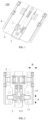
- FIG 1 is a schematic structural diagram of a hinge assembly 100 in a flattened state according to an exemplary embodiment
- FIG 2 is a partial structural schematic diagram of the hinge assembly 100 in FIG 1
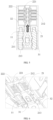
- FIG 3 is an exploded schematic diagram showing a hinge assembly 100 according to an exemplary embodiment.
- the hinge assembly 100 may include a rotating assembly 1 and a hovering mechanism 2.
- the rotating assembly 1 may include a first rotating part 11.
- An axial direction of the first rotating part 11 may be arranged along the direction shown by arrow A in FIG 2 .
- the first rotating part 11 may include a first guide groove 111 extending obliquely around the axial direction of the first rotating part 11.
- the first limiting part 221 includes projections arranged side by side along the axial direction of the first rotating part 11, and the second limiting part 212 includes a plurality of recessed parts arranged side by side along the axial direction of the first rotating part 11.
- the first rotating part 11 can be restricted when at least a part of the projection is located in the recessed part; and if the sliding member 21 is driven to continue sliding under the action of an external force, the projection can slide out from the current recessed part and be cooperated into another recessed part, and at this time, the hinge assembly 100 can be limited to another angle.
- the sliding member 21 slides along the axial direction of the first rotating part 11.
- the sliding member 21, the position limiting member 22 and the rotating assembly 1 are connected through the base body 3, which is beneficial to the integration and centralization of the hinge assembly 100.
- the sliding member 21, the position limiting member 22, and the rotating assembly 1 may also be connected to the housing of the target device or other fixing members, which is not limited in the present disclosure.
- the base body 3 may include a bracket 32 and a cover body 33 assembled with the bracket 32, the guide member 31 may be arranged on the bracket 32, and the cover body 33 may be used for covering, and the sliding member 21 is arranged between the cover body 33 and the bracket 32, to improve the overall aesthetics of the base body 3.
- the fixed support member 4 may include a recessed groove, and the sliding groove may be provided on the inner wall of the recessed groove.
- the mating part 12 includes a sliding groove
- the fixed support member 4 includes a guide rail, which is not limited in the present disclosure.
- the base body 3 may include a first arc-shaped track 34
- the moving part 51 may include an arc-shaped moving part 51, such as a semicircular arc-shaped moving part 51.
- the arc-shaped moving part 51 extends from the end into the first arc-shaped track 34, to cooperate with the first arc-shaped track 34.
- the bracket 32 of the base body 3 may include a first arc-shaped recessed part 321, and the cover 33 of the base body 3 may include a first arc-shaped protrusion 331.
- the first arc-shaped recessed part 321 may be arranged in a semicircular shape.
- the first arc-shaped protrusion 331 can also be arranged in a semicircular shape, but the radius of the first arc-shaped protrusion 331 is smaller than the radius of the first arc-shaped recessed part 321, so that when the first arc-shaped protrusion 331 is cooperated with the first arc-shaped recessed part 321, the first arc-shaped track 34 can be formed due to the difference in radius.
- Only the first arc-shaped protrusion 331 and the first arc-shaped recessed part 321 provided in a semicircular shape is taken as an example for description, in other embodiments, other forms can also be presented, as long as displacement changes can be generated when the moving part 51 rotates relative to the first arc-shaped track 34.
- the second pull rod may include a first hinged part 71 and a second hinged part 72.
- the first hinged part 71 may be rotatably connected with the screen support member 6, and the second hinged part 72 may be rotatably connected with the first pull rod 5.
- the first hinged part 71 may be arranged in a cylindrical shape, the second pull rod 7 includes two second hinged parts 72 spaced apart. Each second hinged part 72 is connected to the first hinged part 71.
- the second hinged part 72 will be outward relative to the screen support member 6, which can provide enough space for the flexible screen provided on the screen support member, ensure that the bending radius of the bent flexible screen is maximized, effectively reduce the bending stress of the flexible screen.
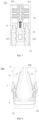
- the present disclosure also provides an electronic device 200.
- the electronic device 200 may include a housing 201, a flexible screen 202, and a hinge assembly 100.
- the flexible screen 202 may be laid flat on the housing 201.
- the end of the rotating assembly 1 of the hinge assembly 100 away from the first rotating part 11 is used to connect to the housing 201.
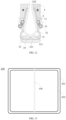
- the first rotating part 11 may be connected to the housing 201 through a fixed support member 4 to drive the housing 201 to rotate, to realize the switching between the unfolded state shown in FIG 13 and the folded state shown in FIG 14 of the electronic device 200.
- the housing 201 may include a left-side housing and a right-side housing, the flexible screen 202 is laid flat on the left-side housing and the right-side housing, and the left-side housing may be connected with the fixed support member 4 on one side of the hinge assembly 100, and the right-side housing can be connected with the fixed support member 4 on the other side of the hinge assembly 100.
- the hinge assembly 100 when the hinge assembly 100 is bent, the two fixed support members 4 of the hinge assembly 100 will approach or move away from each other, thereby driving the left-side housing and the right-side housing to approach or move away from each other, so that the flexible screen 202 is bent or unfolded synchronously.
Landscapes
- Engineering & Computer Science (AREA)
- General Engineering & Computer Science (AREA)
- Computer Hardware Design (AREA)
- Theoretical Computer Science (AREA)
- Microelectronics & Electronic Packaging (AREA)
- Human Computer Interaction (AREA)
- Physics & Mathematics (AREA)
- General Physics & Mathematics (AREA)
- Mechanical Engineering (AREA)
- Signal Processing (AREA)
- Telephone Set Structure (AREA)
Claims (15)
- Scharnieranordnung (100) für eine elektronische Vorrichtung, umfassend:eine drehbare Anordnung (1), wobei die drehbare Anordnung (1) ein erstes drehbares Teil (11) umfasst und das erste drehbare Teil (11) eine erste Führungsnut (111) umfasst, die sich schräg um eine axiale Richtung des ersten drehbaren Teils (11) erstreckt;einen Schwebemechanismus (2), wobei der Schwebemechanismus (2) ein Gleitelement (21) und ein Positionsbegrenzungselement (22) umfasst, das Gleitelement (21) ein vorstehendes Teil (211) umfasst, das vorstehende Teil (211) sich in die erste Führungsnut (111) erstreckt, und das erste drehbare Teil (11) das Gleitelement (21) antreibt, um es bei Drehung entlang der axialen Richtung des ersten drehbaren Teils (11) zu bewegen, wobei das Positionsbegrenzungselement (22) ein erstes Begrenzungsteil (221) umfasst und das Gleitelement (21) ein zweites Begrenzungsteil (212) umfasst, das mit dem ersten Begrenzungsteil (221) zusammenwirkt;wobei eine Drehung des ersten drehbaren Teils (11) begrenzt wird, wenn das erste Begrenzungsteil (221) mit dem zweiten Begrenzungsteil (212) zusammenwirkt, um die Scharnieranordnung (100) in einem aktuellen Zustand zu halten, und die Begrenzung aufgehoben wird, wenn das Zusammenwirken des ersten Begrenzungsteils (221) und des zweiten Begrenzungsteils (212) aufgehoben wird, so dass das erste drehbare Teil (11) sich weiter dreht, um einen Zustand der Scharnieranordnung (100) zu wechseln, dadurch gekennzeichnet, dassdie drehbare Anordnung (1) ferner ein Gegenstück (12) aufweist, das von dem ersten drehbaren Teil (11) entfernt ist, und das erste drehbare Teil (11) dazu verwendet wird, um drehbar mit einem externen Grundkörper (3) oder dem Grundkörper (3) verbunden zu werden, der in der Scharnieranordnung (100) enthalten ist;die Scharnieranordnung (100) ferner umfasst:ein festes Stützelement (4), wobei das feste Stützelement (4) und das Gegenstück (12) entlang einer Richtung senkrecht zur axialen Richtung des ersten drehbaren Teils (11) verschiebbar verbunden sind;eine erste Zugstange (5), deren eines Ende beweglich mit dem Grundkörper (3) verbunden ist und deren anderes Ende drehbar mit dem festen Stützelement (4) verbunden ist;ein Bildschirmstützelement (6), das mit dem festen Stützelement (4) gestapelt ist;eine zweite Zugstange (7), deren eines Ende drehbar mit der ersten Zugstange (5) verbunden ist und deren anderes Ende drehbar mit dem Bildschirmstützelement (6) verbunden ist;wobei die erste Zugstange (5) das feststehende Stützelement (4) zur Bewegung drückt, wenn es sich relativ zum Grundkörper (3) bewegt, wobei das feste Stützelement (4) und das Gegenstück (12) relativ zueinander gleiten und das Bildschirmstützelement (6) durch die zweite Zugstange (7) zur Drehung relativ zum Grundkörper (3) angetrieben wird.
- Scharnieranordnung (100) nach Anspruch 1, wobei eines von erstem Begrenzungsteil (221) und zweitem Begrenzungsteil (212) zumindest einen seitlich entlang der axialen Richtung angeordneten Vorsprung umfasst und das andere von erstem Begrenzungsteil (221) und zweitem Begrenzungsteil (212) zumindest ein seitlich entlang der axialen Richtung angeordnetes vertieftes Teil umfasst;
wobei ein identischer Vorsprung verwendet wird, um mit unterschiedlichen vertieften Teilen zusammenzuwirken, um das erste drehbare Teil (11) in unterschiedlichen Winkeln zu begrenzen, wobei der Vorsprung in das vertiefte Teil gedrückt wird, wenn das erste Begrenzungsteil (221) mit dem zweiten Begrenzungsteil (212) zusammenwirkt. - Scharnieranordnung (100) nach einem der vorstehenden Ansprüche, wobei das Positionsbegrenzungselement (22) ein elastisches Teil (222) umfasst, das elastische Teil (222) in einer Richtung senkrecht zur axialen Richtung des ersten drehbaren Teils (11) angeordnet ist und ein Ende des elastischen Teils (222), das von dem ersten Begrenzungsteil (221) entfernt ist, fest mit einem Grundkörper (3) verbunden ist, wobei das andere Ende des elastischen Teils (222) mit dem ersten Begrenzungsteil (221) oder dem zweiten Begrenzungsteil (212) verbunden ist.
- Scharnieranordnung (100) nach einem der vorstehenden Ansprüche, wobei der Grundkörper (3) entlang der axialen Richtung des ersten drehbaren Teils (11) angeordnet ist und das erste drehbare Teil (11) drehbar mit dem Grundkörper (3) verbunden ist;eines von dem Grundkörper (3) und dem Gleitelement (21) ein Führungselement (31) umfasst und das andere von dem Grundkörper (3) und dem Gleitelement (21) eine zweite Führungsnut (213) umfasst, die mit dem Führungselement (31) zusammenwirkt,wobei der Grundkörper (3) eine Halterung (32) und einen mit der Halterung (32) montierten Abdeckkörper (33) umfasst, das Führungselement (31) an der Halterung (32) vorgesehen ist und das erste drehbare Teil (11) drehbar mit einem Wellenloch verbunden ist, das durch Montage der Halterung (32) und des Abdeckkörpers (33) gebildet wird.
- Scharnieranordnung (100) nach Anspruch 1, wobei die erste Zugstange (5) ein bewegliches Teil (51), ein zweites drehbares Teil (52) und ein Verbindungsteil (53) umfasst, wobei das Verbindungsteil (53) das bewegliche Teil (51) und das zweite drehbare Teil (52) verbindet, das bewegliche Teil (51) beweglich mit dem Grundkörper (3) verbunden ist, das zweite drehbare Teil (52) drehbar mit dem festen Stützelement (4) verbunden ist und das Verbindungsteil (53) drehbar mit der zweiten Zugstange (7) verbunden ist,
wobei das Verbindungsteil (53) ein Durchgangsloch (531) umfasst, die Scharnieranordnung (100) ferner eine zweite drehbare Welle (8) umfasst, die zweite drehbare Welle (8) durch das Durchgangsloch (531) hindurchgeht und drehbar mit der zweiten Zugstange (7) verbunden ist. - Scharnieranordnung (100) nach Anspruch 5, wobei das Verbindungsteil (53) von einer dem Bildschirmstützelement (6) zugewandten Fläche nach innen in eine Richtung weg vom Bildschirmstützelement (6) vertieft ist.
- Scharnieranordnung (100) nach Anspruch 5 oder 6, wobei der Grundkörper (3) eine erste bogenförmige Schiene (34) umfasst, das bewegliche Teil (51) ein bogenförmiges bewegliches Teil (51) umfasst, und das bogenförmige bewegliche Teil (51) mit der ersten bogenförmigen Schiene (34) zusammenwirkt, wenn sich das bogenförmige bewegliche Teil (51) entlang der ersten bogenförmigen Schiene (34) bewegt, das feste Stützelement (4) allmählich vom Grundkörper (3) weg oder auf diesen zu bewegt wird und das Gegenstück (12) und das feste Stützelement (4) relativ zueinander gleiten.
- Scharnieranordnung (100) nach Anspruch 7, wobei der Grundkörper (3) eine Halterung (32) und einen Abdeckkörper (33) umfasst, die Halterung (32) einen ersten bogenförmigen vertieften Teil (321) umfasst, der Abdeckkörper (33) einen ersten bogenförmigen Vorsprung (331) umfasst, der erste bogenförmige Vorsprung (331) in dem ersten bogenförmigen vertieften Teil (321) angeordnet ist, um zusammenzuwirken, um die erste bogenförmige Schiene (34) zu bilden.
- Scharnieranordnung (100) nach einem der vorhergehenden Ansprüche, wobei das Bildschirmstützelement (6) eine Kerbe (61) und eine erste Welle (62) umfasst, die sich von einer Innenwand der Kerbe (61) erstreckt, und die zweite Zugstange (7) drehbar mit der ersten Welle (62) verbunden ist.
- Scharnieranordnung (100) nach einem der vorstehenden Ansprüche, wobei die zweite Zugstange (7) ein erstes Scharnierteil (71) und ein zweites Scharnierteil (72) umfasst, das erste Scharnierteil (71) drehbar mit dem Bildschirmstützelement (6) verbunden ist und das zweite Scharnierteil (72) drehbar mit der ersten Zugstange (5) verbunden ist;
wobei das zweite Scharnierteil (72) zylindrisch geformt ist, zwei erste Scharnierteile (71) in Abständen mit dem zweiten Scharnierteil (72) verbunden sind und eine Ebene einer Achse des ersten Scharnierteils (71) parallel zu und getrennt von einer Ebene einer Achse des zweiten Scharnierteils (72) verläuft, und die Ebene der Achse des zweiten Scharnierteils (72) von dem Bildschirmstützelement (6) relativ zu der Ebene der Achse des ersten Scharnierteils (71) entfernt ist. - Scharnieranordnung (100) nach einem der vorstehenden Ansprüche, wobei das feste Stützelement (4) ein zweites bogenförmiges vertieftes Teil (41) umfasst, das zweite bogenförmige vertiefte Teil (41) an einer Kante des festen Stützelements (4) entfernt von der ersten Zugstange (5) angeordnet ist, die Scharnieranordnung (100) ferner eine Stützplattenabdeckung (9) umfasst, die Stützplattenabdeckung (9) einen zweiten bogenförmigen Vorsprung (91) umfasst, der zweite bogenförmige Vorsprung (91) in dem zweiten bogenförmigen vertieften Teil (41) angeordnet ist, um zusammenzuwirken, um eine zweite bogenförmige Schiene zu bilden;
das Bildschirmstützelement (6) einen Stützkörper und ein bogenförmiges Führungselement (31) umfasst, der Stützkörper und das feste Stützelement (4) gestapelt sind und das bogenförmige Führungselement (31) mit der zweiten bogenförmigen Schiene zusammenwirkt. - Scharnieranordnung (100) nach einem der vorstehenden Ansprüche, wobei ein Satz aus dem festen Stützelement (4), der ersten Zugstange (5) und dem Bildschirmstützelement (6), die miteinander zusammenwirken, an einer Seite des Grundkörpers (3) angeordnet ist;
ein anderer Satz des festen Stützelements (4), der ersten Zugstange (5) und des Bildschirmstützelements (6), die miteinander zusammenwirken, an einer gegenüberliegenden Seite des Grundkörpers (3) angeordnet ist. - Scharnieranordnung (100) nach einem der vorstehenden Ansprüche, wobei eines von dem festen Stützelement (4) und dem Gegenstück (12) eine Gleitnut umfasst und das andere von dem festen Stützelement (4) und dem Gegenstück (12) eine Führungsschiene umfasst, wobei eine Dicke des festen Stützelements (4) von einer Seite nahe dem Grundkörper (3) zu einer Seite weg von dem Grundkörper (3) zunimmt.
- Scharnieranordnung (100) nach einem der vorstehenden Ansprüche, wobei die drehbare Anordnung (1) eine erste drehbare Wellenanordnung und eine zweite drehbare Wellenanordnung umfasst, wobei die erste drehbare Wellenanordnung und die zweite drehbare Wellenanordnung einander gegenüberliegend angeordnet sind und die erste drehbare Wellenanordnung bzw. die zweite drehbare Wellenanordnung das erste drehbare Teil (11) und die erste Führungsnut (111) umfasst, die in dem ersten drehbaren Teil (11) vorgesehen ist;
das Gleitelement (21) eine Vielzahl von vorstehenden Teilen (211) umfasst, wobei zumindest eines der vorstehenden Teile (211) mit der ersten Führungsnut (111) auf dem ersten drehbaren Teil (11) der ersten drehbaren Wellenanordnung zusammenwirkt und zumindest eines der vorstehenden Teile (211) mit der ersten Führungsnut (111) auf dem ersten drehbaren Teil (11) der zweiten drehbaren Wellenanordnung zusammenwirkt. - Elektronische Vorrichtung (200), umfassend:ein Gehäuse (201);einen flexiblen Bildschirm (202);die Scharnieranordnung (100) nach einem der Ansprüche 1 bis 14, wobei ein Ende der drehbaren Anordnung (1), das von dem ersten drehbaren Teil (11) entfernt ist, dazu verwendet wird, mit dem Gehäuse (201) verbunden zu werden, um das Gehäuse (201) in Drehung zu versetzen.
Applications Claiming Priority (1)
| Application Number | Priority Date | Filing Date | Title |
|---|---|---|---|
| CN202110926283.2A CN115704419B (zh) | 2021-08-12 | 2021-08-12 | 铰链组件和电子设备 |
Publications (2)
| Publication Number | Publication Date |
|---|---|
| EP4134780A1 EP4134780A1 (de) | 2023-02-15 |
| EP4134780B1 true EP4134780B1 (de) | 2025-04-09 |
Family
ID=79731018
Family Applications (1)
| Application Number | Title | Priority Date | Filing Date |
|---|---|---|---|
| EP21218457.6A Active EP4134780B1 (de) | 2021-08-12 | 2021-12-31 | Scharnieranordnung und elektronische vorrichtung |
Country Status (3)
| Country | Link |
|---|---|
| US (1) | US11889644B2 (de) |
| EP (1) | EP4134780B1 (de) |
| CN (1) | CN115704419B (de) |
Families Citing this family (8)
| Publication number | Priority date | Publication date | Assignee | Title |
|---|---|---|---|---|
| US11927991B2 (en) * | 2021-05-12 | 2024-03-12 | Dell Products, L.P. | Synchronized hinges for foldable displays |
| CN115370655B (zh) * | 2021-05-18 | 2024-06-25 | 北京小米移动软件有限公司 | 转动模组和电子设备 |
| CN113883158B (zh) * | 2021-09-26 | 2022-05-20 | 维沃移动通信有限公司 | 电子设备 |
| CN115899062A (zh) * | 2021-09-30 | 2023-04-04 | 华为技术有限公司 | 折叠屏设备及铰链组件 |
| CN116123207B (zh) * | 2021-11-12 | 2026-01-16 | 北京小米移动软件有限公司 | 折叠铰链和电子设备 |
| CN116557406A (zh) * | 2022-01-30 | 2023-08-08 | 华为技术有限公司 | 一种转轴机构及电子设备 |
| WO2023159586A1 (zh) * | 2022-02-28 | 2023-08-31 | 京东方科技集团股份有限公司 | 转轴机构及电子设备 |
| US12432287B2 (en) * | 2022-09-01 | 2025-09-30 | Syncmold Enterprise Corp. | Foldable electronic device |
Family Cites Families (11)
| Publication number | Priority date | Publication date | Assignee | Title |
|---|---|---|---|---|
| TWM476453U (en) * | 2013-12-06 | 2014-04-11 | Yuan Deng Metals Industrial Co Ltd | Synchronously-rotatable biaxial hinge |
| CN206918043U (zh) * | 2017-04-19 | 2018-01-23 | 广东欧珀移动通信有限公司 | 转轴组件及可折叠终端 |
| TWI709018B (zh) | 2018-02-14 | 2020-11-01 | 仁寶電腦工業股份有限公司 | 轉軸模組與折疊式電子裝置 |
| KR102444383B1 (ko) * | 2018-08-07 | 2022-09-16 | 후아웨이 테크놀러지 컴퍼니 리미티드 | 회전 샤프트 연결 구조체 및 절첩식 장치 |
| TWI687795B (zh) | 2018-09-27 | 2020-03-11 | 兆利科技工業股份有限公司 | 折疊式裝置的轉軸模組 |
| WO2020159097A1 (en) * | 2019-01-31 | 2020-08-06 | Lg Electronics Inc. | Flexible display device |
| WO2021007750A1 (zh) * | 2019-07-15 | 2021-01-21 | 深圳市柔宇科技有限公司 | 折叠装置及电子设备 |
| CN111857285B (zh) * | 2019-04-25 | 2022-05-10 | 华为技术有限公司 | 升降机构和电子设备 |
| CN114992227B (zh) | 2020-08-10 | 2023-03-03 | Oppo广东移动通信有限公司 | 转轴模组和电子装置 |
| CN112887460B (zh) * | 2021-01-22 | 2023-05-23 | 维沃移动通信有限公司 | 折叠机构和电子设备 |
| CN113067924B (zh) * | 2021-03-19 | 2023-05-23 | 维沃移动通信有限公司 | 折叠机构、支架结构和电子设备 |
-
2021
- 2021-08-12 CN CN202110926283.2A patent/CN115704419B/zh active Active
- 2021-12-30 US US17/566,454 patent/US11889644B2/en active Active
- 2021-12-31 EP EP21218457.6A patent/EP4134780B1/de active Active
Also Published As
| Publication number | Publication date |
|---|---|
| CN115704419B (zh) | 2025-04-22 |
| EP4134780A1 (de) | 2023-02-15 |
| US20230050832A1 (en) | 2023-02-16 |
| CN115704419A (zh) | 2023-02-17 |
| US11889644B2 (en) | 2024-01-30 |
Similar Documents
| Publication | Publication Date | Title |
|---|---|---|
| EP4134780B1 (de) | Scharnieranordnung und elektronische vorrichtung | |
| EP4134782B1 (de) | Scharnieranordnung und elektronische vorrichtung | |
| CN116085377B (zh) | 铰链部件和电子设备 | |
| KR20210089769A (ko) | 회전축 기구 및 이동 단말 | |
| JP2023521480A (ja) | 折り畳み装置および電子デバイス | |
| WO2021007909A1 (zh) | 一种可弯折装置 | |
| CN115405615B (zh) | 铰链机构和电子设备 | |
| TW202037252A (zh) | 折疊式裝置的轉軸模組(五) | |
| CN116696929B (zh) | 一种阻尼机构、折叠铰链及电子设备 | |
| JP2025515617A (ja) | ヒンジ機構および折り畳み式デバイス | |
| WO2023045337A1 (zh) | 铰链部件和电子设备 | |
| CN116498643A (zh) | 一种转轴机构及终端设备 | |
| WO2024222200A1 (zh) | 一种转轴机构及电子设备 | |
| JP7709613B2 (ja) | 回転シャフト機構および電子デバイス | |
| CN116320116A (zh) | 电子设备 | |
| CN216895327U (zh) | 转动模组和电子设备 | |
| WO2023142960A1 (zh) | 折叠机构及电子设备 | |
| CN119496842B (zh) | 可折叠机构和可折叠终端 | |
| CN118746033B (zh) | 转轴机构及电子设备 | |
| WO2025001267A1 (zh) | 一种转轴机构及电子设备 | |
| WO2025261196A1 (zh) | 折叠机构及电子设备 | |
| CN119333468A (zh) | 铰链机构和电子设备 | |
| CN121408348A (zh) | 转轴机构和可折叠电子设备 | |
| CN120856817A (zh) | 折叠机构及电子设备 |
Legal Events
| Date | Code | Title | Description |
|---|---|---|---|
| PUAI | Public reference made under article 153(3) epc to a published international application that has entered the european phase |
Free format text: ORIGINAL CODE: 0009012 |
|
| STAA | Information on the status of an ep patent application or granted ep patent |
Free format text: STATUS: THE APPLICATION HAS BEEN PUBLISHED |
|
| AK | Designated contracting states |
Kind code of ref document: A1 Designated state(s): AL AT BE BG CH CY CZ DE DK EE ES FI FR GB GR HR HU IE IS IT LI LT LU LV MC MK MT NL NO PL PT RO RS SE SI SK SM TR |
|
| STAA | Information on the status of an ep patent application or granted ep patent |
Free format text: STATUS: REQUEST FOR EXAMINATION WAS MADE |
|
| 17P | Request for examination filed |
Effective date: 20230808 |
|
| RBV | Designated contracting states (corrected) |
Designated state(s): AL AT BE BG CH CY CZ DE DK EE ES FI FR GB GR HR HU IE IS IT LI LT LU LV MC MK MT NL NO PL PT RO RS SE SI SK SM TR |
|
| GRAP | Despatch of communication of intention to grant a patent |
Free format text: ORIGINAL CODE: EPIDOSNIGR1 |
|
| STAA | Information on the status of an ep patent application or granted ep patent |
Free format text: STATUS: GRANT OF PATENT IS INTENDED |
|
| RIC1 | Information provided on ipc code assigned before grant |
Ipc: G06F 1/16 20060101AFI20241108BHEP |
|
| INTG | Intention to grant announced |
Effective date: 20241204 |
|
| GRAS | Grant fee paid |
Free format text: ORIGINAL CODE: EPIDOSNIGR3 |
|
| GRAA | (expected) grant |
Free format text: ORIGINAL CODE: 0009210 |
|
| STAA | Information on the status of an ep patent application or granted ep patent |
Free format text: STATUS: THE PATENT HAS BEEN GRANTED |
|
| AK | Designated contracting states |
Kind code of ref document: B1 Designated state(s): AL AT BE BG CH CY CZ DE DK EE ES FI FR GB GR HR HU IE IS IT LI LT LU LV MC MK MT NL NO PL PT RO RS SE SI SK SM TR |
|
| P01 | Opt-out of the competence of the unified patent court (upc) registered |
Free format text: CASE NUMBER: APP_10511/2025 Effective date: 20250303 |
|
| REG | Reference to a national code |
Ref country code: GB Ref legal event code: FG4D |
|
| REG | Reference to a national code |
Ref country code: CH Ref legal event code: EP |
|
| REG | Reference to a national code |
Ref country code: DE Ref legal event code: R096 Ref document number: 602021028844 Country of ref document: DE |
|
| REG | Reference to a national code |
Ref country code: IE Ref legal event code: FG4D |
|
| REG | Reference to a national code |
Ref country code: NL Ref legal event code: MP Effective date: 20250409 |
|
| PG25 | Lapsed in a contracting state [announced via postgrant information from national office to epo] |
Ref country code: NL Free format text: LAPSE BECAUSE OF FAILURE TO SUBMIT A TRANSLATION OF THE DESCRIPTION OR TO PAY THE FEE WITHIN THE PRESCRIBED TIME-LIMIT Effective date: 20250409 |
|
| REG | Reference to a national code |
Ref country code: AT Ref legal event code: MK05 Ref document number: 1784108 Country of ref document: AT Kind code of ref document: T Effective date: 20250409 |
|
| PG25 | Lapsed in a contracting state [announced via postgrant information from national office to epo] |
Ref country code: FI Free format text: LAPSE BECAUSE OF FAILURE TO SUBMIT A TRANSLATION OF THE DESCRIPTION OR TO PAY THE FEE WITHIN THE PRESCRIBED TIME-LIMIT Effective date: 20250409 Ref country code: PT Free format text: LAPSE BECAUSE OF FAILURE TO SUBMIT A TRANSLATION OF THE DESCRIPTION OR TO PAY THE FEE WITHIN THE PRESCRIBED TIME-LIMIT Effective date: 20250811 Ref country code: ES Free format text: LAPSE BECAUSE OF FAILURE TO SUBMIT A TRANSLATION OF THE DESCRIPTION OR TO PAY THE FEE WITHIN THE PRESCRIBED TIME-LIMIT Effective date: 20250409 |
|
| REG | Reference to a national code |
Ref country code: LT Ref legal event code: MG9D |
|
| PG25 | Lapsed in a contracting state [announced via postgrant information from national office to epo] |
Ref country code: NO Free format text: LAPSE BECAUSE OF FAILURE TO SUBMIT A TRANSLATION OF THE DESCRIPTION OR TO PAY THE FEE WITHIN THE PRESCRIBED TIME-LIMIT Effective date: 20250709 Ref country code: GR Free format text: LAPSE BECAUSE OF FAILURE TO SUBMIT A TRANSLATION OF THE DESCRIPTION OR TO PAY THE FEE WITHIN THE PRESCRIBED TIME-LIMIT Effective date: 20250710 |
|
| PG25 | Lapsed in a contracting state [announced via postgrant information from national office to epo] |
Ref country code: PL Free format text: LAPSE BECAUSE OF FAILURE TO SUBMIT A TRANSLATION OF THE DESCRIPTION OR TO PAY THE FEE WITHIN THE PRESCRIBED TIME-LIMIT Effective date: 20250409 |
|
| PG25 | Lapsed in a contracting state [announced via postgrant information from national office to epo] |
Ref country code: BG Free format text: LAPSE BECAUSE OF FAILURE TO SUBMIT A TRANSLATION OF THE DESCRIPTION OR TO PAY THE FEE WITHIN THE PRESCRIBED TIME-LIMIT Effective date: 20250409 |
|
| PG25 | Lapsed in a contracting state [announced via postgrant information from national office to epo] |
Ref country code: HR Free format text: LAPSE BECAUSE OF FAILURE TO SUBMIT A TRANSLATION OF THE DESCRIPTION OR TO PAY THE FEE WITHIN THE PRESCRIBED TIME-LIMIT Effective date: 20250409 |
|
| PG25 | Lapsed in a contracting state [announced via postgrant information from national office to epo] |
Ref country code: AT Free format text: LAPSE BECAUSE OF FAILURE TO SUBMIT A TRANSLATION OF THE DESCRIPTION OR TO PAY THE FEE WITHIN THE PRESCRIBED TIME-LIMIT Effective date: 20250409 |
|
| PG25 | Lapsed in a contracting state [announced via postgrant information from national office to epo] |
Ref country code: RS Free format text: LAPSE BECAUSE OF FAILURE TO SUBMIT A TRANSLATION OF THE DESCRIPTION OR TO PAY THE FEE WITHIN THE PRESCRIBED TIME-LIMIT Effective date: 20250709 |
|
| PG25 | Lapsed in a contracting state [announced via postgrant information from national office to epo] |
Ref country code: IS Free format text: LAPSE BECAUSE OF FAILURE TO SUBMIT A TRANSLATION OF THE DESCRIPTION OR TO PAY THE FEE WITHIN THE PRESCRIBED TIME-LIMIT Effective date: 20250809 |
|
| PG25 | Lapsed in a contracting state [announced via postgrant information from national office to epo] |
Ref country code: LV Free format text: LAPSE BECAUSE OF FAILURE TO SUBMIT A TRANSLATION OF THE DESCRIPTION OR TO PAY THE FEE WITHIN THE PRESCRIBED TIME-LIMIT Effective date: 20250409 |
|
| PGFP | Annual fee paid to national office [announced via postgrant information from national office to epo] |
Ref country code: DE Payment date: 20251126 Year of fee payment: 5 |
|
| PGFP | Annual fee paid to national office [announced via postgrant information from national office to epo] |
Ref country code: GB Payment date: 20251127 Year of fee payment: 5 |
|
| PG25 | Lapsed in a contracting state [announced via postgrant information from national office to epo] |
Ref country code: SM Free format text: LAPSE BECAUSE OF FAILURE TO SUBMIT A TRANSLATION OF THE DESCRIPTION OR TO PAY THE FEE WITHIN THE PRESCRIBED TIME-LIMIT Effective date: 20250409 Ref country code: DK Free format text: LAPSE BECAUSE OF FAILURE TO SUBMIT A TRANSLATION OF THE DESCRIPTION OR TO PAY THE FEE WITHIN THE PRESCRIBED TIME-LIMIT Effective date: 20250409 |
|
| PG25 | Lapsed in a contracting state [announced via postgrant information from national office to epo] |
Ref country code: CZ Free format text: LAPSE BECAUSE OF FAILURE TO SUBMIT A TRANSLATION OF THE DESCRIPTION OR TO PAY THE FEE WITHIN THE PRESCRIBED TIME-LIMIT Effective date: 20250409 |
|
| PG25 | Lapsed in a contracting state [announced via postgrant information from national office to epo] |
Ref country code: EE Free format text: LAPSE BECAUSE OF FAILURE TO SUBMIT A TRANSLATION OF THE DESCRIPTION OR TO PAY THE FEE WITHIN THE PRESCRIBED TIME-LIMIT Effective date: 20250409 |
|
| PG25 | Lapsed in a contracting state [announced via postgrant information from national office to epo] |
Ref country code: SK Free format text: LAPSE BECAUSE OF FAILURE TO SUBMIT A TRANSLATION OF THE DESCRIPTION OR TO PAY THE FEE WITHIN THE PRESCRIBED TIME-LIMIT Effective date: 20250409 |
|
| PG25 | Lapsed in a contracting state [announced via postgrant information from national office to epo] |
Ref country code: IT Free format text: LAPSE BECAUSE OF FAILURE TO SUBMIT A TRANSLATION OF THE DESCRIPTION OR TO PAY THE FEE WITHIN THE PRESCRIBED TIME-LIMIT Effective date: 20250409 |
|
| PG25 | Lapsed in a contracting state [announced via postgrant information from national office to epo] |
Ref country code: RO Free format text: LAPSE BECAUSE OF FAILURE TO SUBMIT A TRANSLATION OF THE DESCRIPTION OR TO PAY THE FEE WITHIN THE PRESCRIBED TIME-LIMIT Effective date: 20250409 |
|
| PLBE | No opposition filed within time limit |
Free format text: ORIGINAL CODE: 0009261 |
|
| STAA | Information on the status of an ep patent application or granted ep patent |
Free format text: STATUS: NO OPPOSITION FILED WITHIN TIME LIMIT |