EP4134653B1 - Repeated moment generation device - Google Patents
Repeated moment generation device Download PDFInfo
- Publication number
- EP4134653B1 EP4134653B1 EP21785489.2A EP21785489A EP4134653B1 EP 4134653 B1 EP4134653 B1 EP 4134653B1 EP 21785489 A EP21785489 A EP 21785489A EP 4134653 B1 EP4134653 B1 EP 4134653B1
- Authority
- EP
- European Patent Office
- Prior art keywords
- principal
- shaft
- eccentric weight
- rotors
- auxiliary
- Prior art date
- Legal status (The legal status is an assumption and is not a legal conclusion. Google has not performed a legal analysis and makes no representation as to the accuracy of the status listed.)
- Active
Links
Images


Classifications
-
- G—PHYSICS
- G01—MEASURING; TESTING
- G01N—INVESTIGATING OR ANALYSING MATERIALS BY DETERMINING THEIR CHEMICAL OR PHYSICAL PROPERTIES
- G01N3/00—Investigating strength properties of solid materials by application of mechanical stress
- G01N3/08—Investigating strength properties of solid materials by application of mechanical stress by applying steady tensile or compressive forces
- G01N3/16—Investigating strength properties of solid materials by application of mechanical stress by applying steady tensile or compressive forces applied through gearing
- G01N3/165—Investigating strength properties of solid materials by application of mechanical stress by applying steady tensile or compressive forces applied through gearing generated by rotation, i.e. centrifugal force
-
- G—PHYSICS
- G01—MEASURING; TESTING
- G01N—INVESTIGATING OR ANALYSING MATERIALS BY DETERMINING THEIR CHEMICAL OR PHYSICAL PROPERTIES
- G01N3/00—Investigating strength properties of solid materials by application of mechanical stress
- G01N3/22—Investigating strength properties of solid materials by application of mechanical stress by applying steady torsional forces
-
- G—PHYSICS
- G01—MEASURING; TESTING
- G01N—INVESTIGATING OR ANALYSING MATERIALS BY DETERMINING THEIR CHEMICAL OR PHYSICAL PROPERTIES
- G01N3/00—Investigating strength properties of solid materials by application of mechanical stress
- G01N3/32—Investigating strength properties of solid materials by application of mechanical stress by applying repeated or pulsating forces
-
- G—PHYSICS
- G01—MEASURING; TESTING
- G01N—INVESTIGATING OR ANALYSING MATERIALS BY DETERMINING THEIR CHEMICAL OR PHYSICAL PROPERTIES
- G01N2203/00—Investigating strength properties of solid materials by application of mechanical stress
- G01N2203/0058—Kind of property studied
- G01N2203/0069—Fatigue, creep, strain-stress relations or elastic constants
- G01N2203/0073—Fatigue
-
- G—PHYSICS
- G01—MEASURING; TESTING
- G01N—INVESTIGATING OR ANALYSING MATERIALS BY DETERMINING THEIR CHEMICAL OR PHYSICAL PROPERTIES
- G01N3/00—Investigating strength properties of solid materials by application of mechanical stress
- G01N3/56—Investigating resistance to wear or abrasion
Definitions
- the present invention relates to a repeated moment generation device that can be used as means for loading a repeated moment on a test piece in a fatigue testing machine adapted to load a repeated moment on a test piece to test a fatigue strength property of a material.
- JP 2011-64508 A it is possible to employ a mechanism or a link mechanism as a combination of an eccentric cam driven to rotate by an inverter motor and a beam member, for example" as repeated moment generation means in a conventional torsional fatigue testing machine.
- the "vibration fatigue testing machine” described in JP 6-337233A includes “a mechanism that generates vibration by a motor rotating an unbalanced pendulum and imparting a load on a sample attached to a sample holder". Also, the “fatigue testing machine” described in Cited Document 3 has a function of "transmitting vibration generated in a direction orthogonal to a rotation shaft core to a specimen and imparting a repeated load on the test piece while an eccentric weight is caused to rotate about the rotation shaft core".
- JP S57 70428 A discloses performing a test under a condition similar to that an engine is actually in operation, by installing a mechanism which repeatedly applies a simultaneous external bending force and external twisting force to the pin section and crank-web section.
- US 2 591 444 A discloses inertia compensated materials fatigue testing machines of the below resonance type having an eccentric weight for producing an alternating centrifugal force to be applied to a specimen.
- JP 3 183237 B2 discloses a vibration device for a vibration table with variable amplitude.
- the conventional fatigue testing machines described in JP 2011-64508 A , JP 6-337233 A and JP 58-163855 A and the like employ, as means for repeatedly imparting a torsional load or an axial load on test pieces, mechanisms that generate a repeated moment or axial vibration in shaft bodies by causing eccentric weights to rotate with members connected to the test pieces.
- forces in up-down and left-right directions repeatedly act on the fatigue testing machines during testing due to centrifugal forces generated through rotation of the eccentric weights, relatively large vibration and noise are generated.
- the fatigue testing machine that is actually used is a one-ton class large-scaled heavy product in the actual situation.
- a problem to be solved by the present invention is to provide a repeated moment generation device capable of realizing size reduction, weight reduction, and noise reduction for a fatigue testing machine.
- a repeated moment generation device includes: a principal shaft that is for transmitting a repeated torsional moment; two principal bearing members that rotatably hold the principal shaft; two lever members that are attached to the principal shaft at positions separated in a shaft center direction of the principal shaft in a state in which each of the lever members perpendicularly intersects a shaft center of the principal shaft; two principal eccentric weight rotors that are provided at shaft bodies that are rotatably and axially supported by the lever members in a state in which each of the two principal eccentric weight rotors is parallel to the principal shaft, at symmetrical positions with the principal shaft interposed therebetween in a region where the lever members face each other; two auxiliary eccentric weight rotors that are provided such that each of the two auxiliary eccentric weight rotors is rotatable about a shaft body that is parallel to the principal shaft, between two pairs of auxiliary bearing members provided at members that are continued from the principal bearing members; and drive means for causing the two principal eccentric weight rotors and the two auxiliary
- two centrifugal forces generated through rotation of the two principal eccentric weight rotors have mutually the same magnitude and have acting directions that are opposite by 180 degrees
- two centrifugal forces generated through rotation of the two auxiliary eccentric weight rotors have mutually the same magnitude and have acting directions that are opposite by 180 degrees.
- a couple of forces defined by a product of two centrifugal forces generated through rotation of the two principal eccentric weight rotors and a distance between lines of action of the two centrifugal forces and a couple of forces defined by a product of two centrifugal forces generated through rotation of the two auxiliary eccentric weight rotors and a distance between lines of action of the two centrifugal forces have mutually the same magnitude and have opposite rotation directions.
- the two principal bearing members and the two pairs of auxiliary bearing members can be provided at a table member such that shaft centers of shaft bodies of the two principal eccentric weight rotors and shaft centers of shaft bodies of the two auxiliary eccentric weight rotors are parallel to each other.
- the repeated moment generation device can also include the following configuration requirements and it is thus possible to realize simplification and downsizing of the device.
- the repeated moment generation device 100 includes: a principal shaft 1 that is for transmitting a repeated moment; principal bearing members 2a, 2b that are provided to stand on an upper surface of the table 24 at a predetermined distance therebetween to rotatably hold the principal shaft 1; a pair of lever members 3a, 3b that are attached to the principal shaft 1 at positions that are separated in a direction of a shaft center 1c of the principal shaft 1 in a state in which each of the lever members 3a and 3b perpendicularly intersects the principal shaft 1; shaft bodies 4 and 5 that are provided such that the shaft bodies 4, 5 are rotatable about shaft centers 4c, 5c (see Figure 2 ) that are parallel to the principal shaft 1, respectively, at symmetrical positions with the principal shaft 1 interposed therebetween in a region where the lever members 3a, 3b face each other; two principal eccentric
- the table 24 is a quadrangular flat plate-shaped member and is maintained in a horizontal state by four support members 25 disposed at four corner portions 24c thereof on the lower surface side.
- the support members 25 have L-shape horizontal sections and are provided with bottom plates 25b on the lower surface side.
- the four corner portions 24c of the table 24 are fixed in a state in which the corner portions 24c are placed on upper surfaces 25a of the four support members 25, respectively, and a quadrangular flat plate-shaped bottom table 26 is disposed on the bottom plates 25b located at the four positions.
- the lower surface of the table 24 that is a member continued from the principal bearing members 2a, 2b is provided with a plurality of auxiliary bearing members 8a, 8b, 9a, 9b in a suspended manner, a shaft body 10 having a shaft center 10c (see Figure 3 ) that is parallel with the principal shaft 1 is disposed to be rotatable about the shaft center 10c between the facing auxiliary bearing members 8a, 8b, and a shaft body 11 having a shaft center 11c that is parallel with the principal shaft 1 is disposed to be rotatable about the shaft center 11c between the facing auxiliary bearing members 9a, 9b.
- the auxiliary eccentric weight rotor 12 is rotatable along with the shaft body 10
- the auxiliary eccentric weight rotor 13 is rotatable along with the shaft body 11.
- the principal eccentric weight rotor 7 includes a columnar diameter expanded portion 7b that is formed at a part of the shaft body 5 and a weight member 7c that is attached with the diameter expanded portion 7b penetrating in a direction that is orthogonal to the shaft center 5c.
- the weight member 7c includes a bolt member 7e that is screwed to penetrate through the diameter expanded portion 7b, a weight 7g that is attached to an end portion of the bolt member 7e, and a locking nut 7d that is screwed onto the bolt member 7e to lock the bolt member 7e at the diameter expanded portion 7b.
- a male screw is formed on the outer circumference of the bolt member 7e, and an end portion of the weight member 7c on the opposite side is provided with a short columnar-shaped stopper portion 7f with a diameter expanded as compared with the male screw portion.
- the bolt member 7e having a male screw at the outer circumference thereof is screwed in a state in which it penetrates through the diameter expanded portion 7b having a female screw hole (corresponding to the female screw hole 6h in Figure 2 ), and it is possible to decenter a center of gravity 7G (see Figure 3 ) of the weight member 7c in a direction away from the shaft center 5c by causing the bolt member 7e to rotate about the shaft center thereof, causing the bolt member 7e to move in a longitudinal direction, and thereby changing the distance between the weight 7g and the shaft center 5c of the shaft body 5.
- the principal eccentric weight rotor 7 rotates with rotation of the shaft body 5 that rotates due to a drive force of a motor 14 as will be described later in a state in which the center of gravity 7G of the weight member 7c is decentered from the shaft center 5c, then the weight member 7c also rotates about the shaft center 5c, and a centrifugal force 7a with the size determined by the amount of eccentricity of the center of gravity 7G and the rotation frequency is generated in the shaft center direction of the bolt member 7e. Since a direction in which the centrifugal force 7a acts rotates about the shaft center 5c, a force changing in up-down and left-right directions with the rotation is transmitted to the shaft body 5 and members coupled to the shaft body 5.
- the principal eccentric weight rotor 6 and the two auxiliary eccentric weight rotors 12 and 13 also have functions that are similar to that of the principal eccentric weight rotor 7.
- the motor 14 As drive means for causing the two principal eccentric weight rotors 6 and 7 and the two auxiliary eccentric weight rotors 12 and 13 to synchronously rotate, the motor 14, middle timing pulleys 15, 16, large timing pulleys 17, 18, small timing pulleys 19a, 19b, 20a, 20b, and timing belts 21, 22, 23 are included.
- the middle timing pulley 15 and the large timing pulley 17 are attached to a rotation shaft 14a of the motor 14, and the middle timing pulley 16 and the large timing pulley 18 are attached to the principal shaft 1 via a bearing.
- the rotation shaft 14a of the motor 14 is parallel with the principal shaft 1
- the middle timing pulley 15 and the large timing pulley 17 on the side of the motor 14 are located immediately below the middle timing pulley 16 and the large timing pulley 18 on the side of the principal shaft 1
- the middle timing pulleys 15, 16 and the large timing pulleys 17 and 18 are disposed to face each other such that the middle timing pulleys 15 and 16 are disposed in series and the large timing pulleys 17 and 18 are disposed in series, in the up-down direction.
- the small timing pulleys 19a, 19b are attached to the shaft bodies 4, 5, and small timing pulleys 20a, 20b are attached to the shaft bodies 10, 11.
- the small timing pulleys 19a, 19b are disposed in series with the large timing pulley 18 interposed therebetween, and the small timing pulleys 20a, 20b are disposed in series with the large timing pulley 17 interposed therebetween.
- the sizes (outer diameters) of the small timing pulleys 19a, 19b, 20a, 20b are the same, the sizes (outer diameters) of the middle timing pulleys 15, 16 are also the same, and the sizes (outer diameters) of the large timing pulleys 17, 18 are also the same.
- the middle timing pulley 15 and the middle timing pulley 16 are interlocked by the timing belt 21
- the small timing pulleys 19a, 19b and the large timing pulley 18 are interlocked by the timing belt 22
- the small timing pulleys 20a, 20b and the large timing pulley 17 are interlocked by the timing belt 23.
- the large timing pulley 17 and the middle timing pulley 15 attached integrally to the rotation shaft 14a rotate in the same direction at the same rotation frequency
- the rotation of the middle timing pulley 15 is transmitted to the middle timing pulley 16 via the timing belt 21, and the middle timing pulleys 15, 16 rotate in the same direction at the same rotation frequency as those of the rotation shaft 14a of the motor 14.
- the rotation of the middle timing pulley 16 is transmitted to the large timing pulley 18 integrated with the middle timing pulley 15 via the principal shaft 1, and the large timing pulleys 17, 18 thus rotate in the same direction at the same rotation frequency.
- the rotation of the large timing pulley 17 is transmitted to the small timing pulleys 20a, 20b via the timing belt 23
- the rotation of the large timing pulley 18 is transmitted to the small timing pulleys 20a, 20b via the timing belt 22
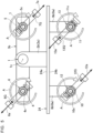
- the two principal eccentric weight rotors 6, 7 are disposed such that eccentricity directions of the centers of gravity 6G, 7G (the directions of the centrifugal forces 6a, 7a) are different from each other by 180 degrees around the shaft centers 4c, 5c, of the shaft bodies 4, 5 thereof as illustrated in Figure 3 .
- the two auxiliary eccentric weight rotors 12, 13 are disposed such that eccentricity directions of the centers of gravity 12G, 13G thereof (the directions of the centrifugal forces 12a, 13a) are different from each other by 180 degrees around the shaft centers 10c, 11c of the shaft bodies 10, 11 thereof.
- the eccentricity direction of the principal eccentric weight rotor 6, which corresponds to one of the two principal eccentric weight rotors, (the direction of the centrifugal force 6a) and the eccentricity direction of the auxiliary eccentric weight rotor 12 (the direction of the centrifugal force 12a) located on the same side as the principal eccentric weight rotor 6 with respect to the principal shaft 1 are different from each other by 180 degrees around the shaft centers 4c, 10c of the shaft bodies 4, 10 thereof.
- each of the two principal eccentric weight rotors 6, 7 and the two auxiliary eccentric weight rotors 12, 13 rotates in the clockwise direction (the arrow A direction) at the same rotation frequency as illustrated in Figure 3 .
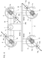
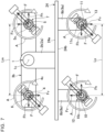
- Figures 3 to 6 display states in which the two principal eccentric weight rotors 6, 7 and the two auxiliary eccentric weight rotors 12, 13 rotate with elapse of time in order.
- the two principal eccentric weight rotors 6, 7 rotate while maintaining a relationship in which the directions of the centrifugal forces 6a, 7a thereof are different from each other by 180 degrees around the rotational center lines (shaft centers 4c, 5c), and the two auxiliary eccentric weight rotors 12, 13 rotate while maintaining a relationship in which the directions of the centrifugal forces 12a, 13a thereof are different from each other by 180 degrees around the rotational center lines (shaft centers 10c, 11c) .
- the two centrifugal forces 6a, 7a generated through rotation of the two principal eccentric weight rotors 6, 7 have mutually the same magnitude and have acting directions that are opposite by 180 degrees
- the two centrifugal forces 12a, 13a generated through rotation of the two auxiliary eccentric weight rotors 12, 13 have mutually the same magnitude and have acting directions that are opposite by 180 degrees.
- a couple of forces defined by a product of the two centrifugal forces 6a, 7a generated through rotation of the two principal eccentric weight rotors 6, 7 and the distance between lines of action of the two centrifugal forces 6a, 7a and a couple of forces defined by a product of the two centrifugal forces 12a, 13a generated through rotation of the two auxiliary eccentric weight rotors 12, 13 and the distance between lines of action of the two centrifugal forces 12a, 13a have mutually the same magnitude and have rotation directions that are opposite.
- the two principal bearing members 2a, 2b and the two pairs of auxiliary bearing members 8a, 8b, 9a, 9b are disposed on the table 24 such that the shaft centers 4c, 5c of the shaft bodies 4, 5 of the two principal eccentric weight rotors 6, 7 and the shaft centers 10c, 11c of the shaft bodies 10, 11 of the auxiliary eccentric weight rotors 12, 13 are parallel to each other.
- the two principal eccentric weight rotors 6, 7 rotate while maintaining a relationship in which the directions of the centrifugal forces 6a, 7a thereof are different from each other by 180 degrees around the rotational center lines (shaft centers 4c, 5c), and the two auxiliary eccentric weight rotors 12, 13 rotate while maintaining a relationship in which the directions of the centrifugal forces 12a, 13a thereof are different from each other by 180 degrees around the rotational center lines (shaft centers 10c, 11c).
- the direction of the centrifugal force 6a of the principal eccentric weight rotor 6, which is one of the two principal eccentric weight rotors, and the direction of the centrifugal force 12a of the auxiliary eccentric weight rotor 12 located on the same side as the principal eccentric weight rotor 6 with respect to the principal shaft 1 maintain a relationship in which they are different from each other by 180 degrees around the rotational center lines (shaft centers 4c, 10c) thereof.
- centrifugal forces F are considered separately as forces in two directions that are orthogonal to each other (a horizontal force component Fh and a vertical force component Fv)
- the horizontal force component Fh and the vertical force component Fv in the principal eccentric weight rotor 6 and the horizontal force component Fh and the vertical force component Fv in the principal eccentric weight rotor 7 have mutually the same force magnitude in the vertical direction and the horizontal direction and have force directions that are opposite by 180 degrees, and the forces in the vertical direction and the horizontal direction are thus cancelled out by each other and satisfy an equilibrium condition of force.
- the horizontal force component Fh and the vertical force component Fv in the auxiliary eccentric weight rotor 12 and the horizontal force component Fh and the vertical force component Fv in the auxiliary eccentric weight rotor 13 have mutually the same force magnitude in the vertical direction and the horizontal direction and have force directions that are opposite by 180 degrees, the forces in the vertical direction and the horizontal direction are thus cancelled out and satisfy the equilibrium condition of force.
- the testing machine (not illustrated) does not perform rotational movement.
- vibration control means since it is not necessary to provide vibration control means, vibration isolation means, sound isolation means, and the like, if the aforementioned vibration reduction (theoretically, elimination of vibration) and noise reduction are realized, it is also possible to realize size reduction of the repeated moment generation device 100. Moreover, since it is not necessary to increase the mass of the testing machine as in the related art for the purpose of curbing vibration, it is also possible to realize weight reduction of the testing machine.
- the repeated moment generation device 100 includes the following configuration requirements as illustrated in Figures 3 to 6 , it is possible to realize simplification and downsizing of the device.
- repeated moment generation device 100 described on the basis of Figures 1 to 7 is an example of the repeated moment generation device according to the present invention.
- the repeated moment generation device can be widely used in a fatigue testing machine adapted to load a repeated load on a test piece to test a fatigue strength property of a material.
Landscapes
- General Health & Medical Sciences (AREA)
- General Physics & Mathematics (AREA)
- Life Sciences & Earth Sciences (AREA)
- Chemical & Material Sciences (AREA)
- Analytical Chemistry (AREA)
- Biochemistry (AREA)
- Immunology (AREA)
- Physics & Mathematics (AREA)
- Health & Medical Sciences (AREA)
- Pathology (AREA)
- Investigating Strength Of Materials By Application Of Mechanical Stress (AREA)
- Transmission Devices (AREA)
- Connection Of Motors, Electrical Generators, Mechanical Devices, And The Like (AREA)
- Testing Of Balance (AREA)
Applications Claiming Priority (2)
| Application Number | Priority Date | Filing Date | Title |
|---|---|---|---|
| JP2020069940 | 2020-04-08 | ||
| PCT/JP2021/014813 WO2021206125A1 (ja) | 2020-04-08 | 2021-04-07 | 繰り返しモーメント発生装置 |
Publications (3)
| Publication Number | Publication Date |
|---|---|
| EP4134653A1 EP4134653A1 (en) | 2023-02-15 |
| EP4134653A4 EP4134653A4 (en) | 2023-09-27 |
| EP4134653B1 true EP4134653B1 (en) | 2024-11-20 |
Family
ID=78022890
Family Applications (1)
| Application Number | Title | Priority Date | Filing Date |
|---|---|---|---|
| EP21785489.2A Active EP4134653B1 (en) | 2020-04-08 | 2021-04-07 | Repeated moment generation device |
Country Status (4)
| Country | Link |
|---|---|
| US (1) | US12158451B2 (https=) |
| EP (1) | EP4134653B1 (https=) |
| JP (1) | JP7604010B2 (https=) |
| WO (1) | WO2021206125A1 (https=) |
Families Citing this family (1)
| Publication number | Priority date | Publication date | Assignee | Title |
|---|---|---|---|---|
| JP7442809B2 (ja) * | 2020-07-02 | 2024-03-05 | 学校法人福岡大学 | 繰り返しモーメント発生装置 |
Family Cites Families (17)
| Publication number | Priority date | Publication date | Assignee | Title |
|---|---|---|---|---|
| US2591444A (en) | 1946-10-22 | 1952-04-01 | Baldwin Lima Hamilton Corp | Fatigue testing machine |
| JPS5232264B1 (https=) * | 1968-12-28 | 1977-08-20 | ||
| JPS5546244U (https=) * | 1978-09-20 | 1980-03-26 | ||
| JPH0222672Y2 (https=) * | 1979-10-16 | 1990-06-19 | ||
| JPS5770428A (en) * | 1980-10-20 | 1982-04-30 | Kubota Ltd | Equipment for fatigue test of crank-shaft of engine |
| JPS57199084U (https=) * | 1981-06-16 | 1982-12-17 | ||
| JPS6025569Y2 (ja) | 1983-03-10 | 1985-07-31 | 株式会社島津製作所 | 疲労試験機 |
| JPS61105843U (https=) * | 1984-12-18 | 1986-07-05 | ||
| JP2607377B2 (ja) * | 1987-12-28 | 1997-05-07 | 伊藤精機株式会社 | 構造物試験用起振機 |
| JP2681089B2 (ja) * | 1989-06-12 | 1997-11-19 | 調和工業株式会社 | 振動装置 |
| JP3296627B2 (ja) | 1993-05-28 | 2002-07-02 | 財団法人鉄道総合技術研究所 | 振動疲労試験機 |
| JP3183237B2 (ja) * | 1997-11-21 | 2001-07-09 | 株式会社ケイ | 可変型振動テーブル用振動装置 |
| JP3799022B2 (ja) * | 2003-02-24 | 2006-07-19 | 酒井重工業株式会社 | 振動機構及び振動ローラ |
| JP4807730B2 (ja) * | 2005-08-25 | 2011-11-02 | 国立大学法人名古屋大学 | 曲げ疲労試験機及び曲げ疲労試験方法 |
| US7827868B2 (en) | 2007-11-30 | 2010-11-09 | Dynamic Systems, Inc. | Apparatus for a cam-based jack assembly for use in materials, testing machines and an accompanying method for use therewith |
| JP5334056B2 (ja) | 2009-09-15 | 2013-11-06 | 学校法人福岡大学 | 疲労試験機 |
| CN201926593U (zh) * | 2010-10-15 | 2011-08-10 | 沈阳航空航天大学 | 航空导管组件旋转弯曲疲劳试验机 |
-
2021
- 2021-04-07 WO PCT/JP2021/014813 patent/WO2021206125A1/ja not_active Ceased
- 2021-04-07 JP JP2022514111A patent/JP7604010B2/ja active Active
- 2021-04-07 EP EP21785489.2A patent/EP4134653B1/en active Active
-
2022
- 2022-10-07 US US17/961,773 patent/US12158451B2/en active Active
Also Published As
| Publication number | Publication date |
|---|---|
| EP4134653A4 (en) | 2023-09-27 |
| US20230035932A1 (en) | 2023-02-02 |
| WO2021206125A1 (ja) | 2021-10-14 |
| US12158451B2 (en) | 2024-12-03 |
| EP4134653A1 (en) | 2023-02-15 |
| JP7604010B2 (ja) | 2024-12-23 |
| JPWO2021206125A1 (https=) | 2021-10-14 |
Similar Documents
| Publication | Publication Date | Title |
|---|---|---|
| AU2019429490B2 (en) | Six-degree-of-freedom series-parallel electromagnetic vibration test stand | |
| WO2020164185A1 (zh) | 五自由度变胞式电磁振动试验台 | |
| JP5364154B2 (ja) | 歯車デバイス、好ましくはモーターデバイス | |
| CN108362586B (zh) | 共振弯曲疲劳试验机 | |
| EP4134653B1 (en) | Repeated moment generation device | |
| EP1887338A1 (en) | Transportation packaging test apparatus | |
| CN112436674B (zh) | 一种无级变化激振器装置 | |
| JP6235853B2 (ja) | 回転変動試験機 | |
| CN109926312B (zh) | 配活配重块的偏心块及振动器、振动筛 | |
| US3796092A (en) | Torsion test stand | |
| JPH07120351A (ja) | 振動試験機 | |
| JPS6115003B2 (https=) | ||
| RU1835500C (ru) | Установка дл испытаний материалов на усталость | |
| SU1714429A1 (ru) | Инерционный нагружатель стенда дл испытани образцов на усталость | |
| Kim et al. | Dynamic analysis of a pulley-belt system with different pulley radii and support stiffness | |
| JP2016168563A (ja) | 遠心処理装置 | |
| JP2004174473A (ja) | 起振力の制御方法、および同制御装置 | |
| SU1523192A1 (ru) | Вибровозбудитель | |
| JP6418553B2 (ja) | 遠心処理装置 | |
| RU2464108C1 (ru) | Дебалансный вибровозбудитель | |
| JP7442809B2 (ja) | 繰り返しモーメント発生装置 | |
| CZ2005717A3 (cs) | Multifunkcní vyvazovací systém | |
| SU1397798A1 (ru) | Установка дл испытаний материалов на усталость | |
| JPH06273261A (ja) | 振動発生機 | |
| JPS6052046B2 (ja) | 振動部品供給機 |
Legal Events
| Date | Code | Title | Description |
|---|---|---|---|
| STAA | Information on the status of an ep patent application or granted ep patent |
Free format text: STATUS: THE INTERNATIONAL PUBLICATION HAS BEEN MADE |
|
| PUAI | Public reference made under article 153(3) epc to a published international application that has entered the european phase |
Free format text: ORIGINAL CODE: 0009012 |
|
| STAA | Information on the status of an ep patent application or granted ep patent |
Free format text: STATUS: REQUEST FOR EXAMINATION WAS MADE |
|
| 17P | Request for examination filed |
Effective date: 20221027 |
|
| AK | Designated contracting states |
Kind code of ref document: A1 Designated state(s): AL AT BE BG CH CY CZ DE DK EE ES FI FR GB GR HR HU IE IS IT LI LT LU LV MC MK MT NL NO PL PT RO RS SE SI SK SM TR |
|
| DAV | Request for validation of the european patent (deleted) | ||
| DAX | Request for extension of the european patent (deleted) | ||
| A4 | Supplementary search report drawn up and despatched |
Effective date: 20230829 |
|
| RIC1 | Information provided on ipc code assigned before grant |
Ipc: G01N 3/32 20060101ALI20230823BHEP Ipc: G01N 3/22 20060101ALI20230823BHEP Ipc: G01N 3/34 20060101AFI20230823BHEP |
|
| GRAP | Despatch of communication of intention to grant a patent |
Free format text: ORIGINAL CODE: EPIDOSNIGR1 |
|
| STAA | Information on the status of an ep patent application or granted ep patent |
Free format text: STATUS: GRANT OF PATENT IS INTENDED |
|
| RIC1 | Information provided on ipc code assigned before grant |
Ipc: G01N 3/32 20060101ALI20240603BHEP Ipc: G01N 3/22 20060101ALI20240603BHEP Ipc: G01N 3/34 20060101AFI20240603BHEP |
|
| INTG | Intention to grant announced |
Effective date: 20240626 |
|
| GRAS | Grant fee paid |
Free format text: ORIGINAL CODE: EPIDOSNIGR3 |
|
| GRAA | (expected) grant |
Free format text: ORIGINAL CODE: 0009210 |
|
| STAA | Information on the status of an ep patent application or granted ep patent |
Free format text: STATUS: THE PATENT HAS BEEN GRANTED |
|
| AK | Designated contracting states |
Kind code of ref document: B1 Designated state(s): AL AT BE BG CH CY CZ DE DK EE ES FI FR GB GR HR HU IE IS IT LI LT LU LV MC MK MT NL NO PL PT RO RS SE SI SK SM TR |
|
| RAP3 | Party data changed (applicant data changed or rights of an application transferred) |
Owner name: FUKUOKA UNIVERSITY |
|
| REG | Reference to a national code |
Ref country code: GB Ref legal event code: FG4D |
|
| RIN1 | Information on inventor provided before grant (corrected) |
Inventor name: ENDO, MASAHIRO |
|
| REG | Reference to a national code |
Ref country code: CH Ref legal event code: EP |
|
| REG | Reference to a national code |
Ref country code: DE Ref legal event code: R096 Ref document number: 602021022152 Country of ref document: DE |
|
| REG | Reference to a national code |
Ref country code: IE Ref legal event code: FG4D |
|
| REG | Reference to a national code |
Ref country code: LT Ref legal event code: MG9D |
|
| REG | Reference to a national code |
Ref country code: NL Ref legal event code: MP Effective date: 20241120 |
|
| PG25 | Lapsed in a contracting state [announced via postgrant information from national office to epo] |
Ref country code: IS Free format text: LAPSE BECAUSE OF FAILURE TO SUBMIT A TRANSLATION OF THE DESCRIPTION OR TO PAY THE FEE WITHIN THE PRESCRIBED TIME-LIMIT Effective date: 20250320 Ref country code: PT Free format text: LAPSE BECAUSE OF FAILURE TO SUBMIT A TRANSLATION OF THE DESCRIPTION OR TO PAY THE FEE WITHIN THE PRESCRIBED TIME-LIMIT Effective date: 20250320 Ref country code: HR Free format text: LAPSE BECAUSE OF FAILURE TO SUBMIT A TRANSLATION OF THE DESCRIPTION OR TO PAY THE FEE WITHIN THE PRESCRIBED TIME-LIMIT Effective date: 20241120 |
|
| PG25 | Lapsed in a contracting state [announced via postgrant information from national office to epo] |
Ref country code: FI Free format text: LAPSE BECAUSE OF FAILURE TO SUBMIT A TRANSLATION OF THE DESCRIPTION OR TO PAY THE FEE WITHIN THE PRESCRIBED TIME-LIMIT Effective date: 20241120 Ref country code: NL Free format text: LAPSE BECAUSE OF FAILURE TO SUBMIT A TRANSLATION OF THE DESCRIPTION OR TO PAY THE FEE WITHIN THE PRESCRIBED TIME-LIMIT Effective date: 20241120 |
|
| REG | Reference to a national code |
Ref country code: AT Ref legal event code: MK05 Ref document number: 1743968 Country of ref document: AT Kind code of ref document: T Effective date: 20241120 |
|
| PG25 | Lapsed in a contracting state [announced via postgrant information from national office to epo] |
Ref country code: BG Free format text: LAPSE BECAUSE OF FAILURE TO SUBMIT A TRANSLATION OF THE DESCRIPTION OR TO PAY THE FEE WITHIN THE PRESCRIBED TIME-LIMIT Effective date: 20241120 |
|
| PG25 | Lapsed in a contracting state [announced via postgrant information from national office to epo] |
Ref country code: ES Free format text: LAPSE BECAUSE OF FAILURE TO SUBMIT A TRANSLATION OF THE DESCRIPTION OR TO PAY THE FEE WITHIN THE PRESCRIBED TIME-LIMIT Effective date: 20241120 |
|
| PG25 | Lapsed in a contracting state [announced via postgrant information from national office to epo] |
Ref country code: NO Free format text: LAPSE BECAUSE OF FAILURE TO SUBMIT A TRANSLATION OF THE DESCRIPTION OR TO PAY THE FEE WITHIN THE PRESCRIBED TIME-LIMIT Effective date: 20250220 |
|
| PG25 | Lapsed in a contracting state [announced via postgrant information from national office to epo] |
Ref country code: LV Free format text: LAPSE BECAUSE OF FAILURE TO SUBMIT A TRANSLATION OF THE DESCRIPTION OR TO PAY THE FEE WITHIN THE PRESCRIBED TIME-LIMIT Effective date: 20241120 Ref country code: AT Free format text: LAPSE BECAUSE OF FAILURE TO SUBMIT A TRANSLATION OF THE DESCRIPTION OR TO PAY THE FEE WITHIN THE PRESCRIBED TIME-LIMIT Effective date: 20241120 Ref country code: GR Free format text: LAPSE BECAUSE OF FAILURE TO SUBMIT A TRANSLATION OF THE DESCRIPTION OR TO PAY THE FEE WITHIN THE PRESCRIBED TIME-LIMIT Effective date: 20250221 |
|
| PG25 | Lapsed in a contracting state [announced via postgrant information from national office to epo] |
Ref country code: PL Free format text: LAPSE BECAUSE OF FAILURE TO SUBMIT A TRANSLATION OF THE DESCRIPTION OR TO PAY THE FEE WITHIN THE PRESCRIBED TIME-LIMIT Effective date: 20241120 |
|
| PG25 | Lapsed in a contracting state [announced via postgrant information from national office to epo] |
Ref country code: RS Free format text: LAPSE BECAUSE OF FAILURE TO SUBMIT A TRANSLATION OF THE DESCRIPTION OR TO PAY THE FEE WITHIN THE PRESCRIBED TIME-LIMIT Effective date: 20250220 |
|
| PG25 | Lapsed in a contracting state [announced via postgrant information from national office to epo] |
Ref country code: SM Free format text: LAPSE BECAUSE OF FAILURE TO SUBMIT A TRANSLATION OF THE DESCRIPTION OR TO PAY THE FEE WITHIN THE PRESCRIBED TIME-LIMIT Effective date: 20241120 |
|
| PGFP | Annual fee paid to national office [announced via postgrant information from national office to epo] |
Ref country code: DE Payment date: 20250317 Year of fee payment: 5 |
|
| PG25 | Lapsed in a contracting state [announced via postgrant information from national office to epo] |
Ref country code: DK Free format text: LAPSE BECAUSE OF FAILURE TO SUBMIT A TRANSLATION OF THE DESCRIPTION OR TO PAY THE FEE WITHIN THE PRESCRIBED TIME-LIMIT Effective date: 20241120 |
|
| PG25 | Lapsed in a contracting state [announced via postgrant information from national office to epo] |
Ref country code: EE Free format text: LAPSE BECAUSE OF FAILURE TO SUBMIT A TRANSLATION OF THE DESCRIPTION OR TO PAY THE FEE WITHIN THE PRESCRIBED TIME-LIMIT Effective date: 20241120 |
|
| PG25 | Lapsed in a contracting state [announced via postgrant information from national office to epo] |
Ref country code: RO Free format text: LAPSE BECAUSE OF FAILURE TO SUBMIT A TRANSLATION OF THE DESCRIPTION OR TO PAY THE FEE WITHIN THE PRESCRIBED TIME-LIMIT Effective date: 20241120 |
|
| PG25 | Lapsed in a contracting state [announced via postgrant information from national office to epo] |
Ref country code: SK Free format text: LAPSE BECAUSE OF FAILURE TO SUBMIT A TRANSLATION OF THE DESCRIPTION OR TO PAY THE FEE WITHIN THE PRESCRIBED TIME-LIMIT Effective date: 20241120 |
|
| PG25 | Lapsed in a contracting state [announced via postgrant information from national office to epo] |
Ref country code: CZ Free format text: LAPSE BECAUSE OF FAILURE TO SUBMIT A TRANSLATION OF THE DESCRIPTION OR TO PAY THE FEE WITHIN THE PRESCRIBED TIME-LIMIT Effective date: 20241120 |
|
| PG25 | Lapsed in a contracting state [announced via postgrant information from national office to epo] |
Ref country code: IT Free format text: LAPSE BECAUSE OF FAILURE TO SUBMIT A TRANSLATION OF THE DESCRIPTION OR TO PAY THE FEE WITHIN THE PRESCRIBED TIME-LIMIT Effective date: 20241120 |
|
| REG | Reference to a national code |
Ref country code: DE Ref legal event code: R097 Ref document number: 602021022152 Country of ref document: DE |
|
| PG25 | Lapsed in a contracting state [announced via postgrant information from national office to epo] |
Ref country code: SE Free format text: LAPSE BECAUSE OF FAILURE TO SUBMIT A TRANSLATION OF THE DESCRIPTION OR TO PAY THE FEE WITHIN THE PRESCRIBED TIME-LIMIT Effective date: 20241120 |
|
| PLBE | No opposition filed within time limit |
Free format text: ORIGINAL CODE: 0009261 |
|
| STAA | Information on the status of an ep patent application or granted ep patent |
Free format text: STATUS: NO OPPOSITION FILED WITHIN TIME LIMIT |
|
| 26N | No opposition filed |
Effective date: 20250821 |
|
| REG | Reference to a national code |
Ref country code: CH Ref legal event code: H13 Free format text: ST27 STATUS EVENT CODE: U-0-0-H10-H13 (AS PROVIDED BY THE NATIONAL OFFICE) Effective date: 20251125 |
|
| PG25 | Lapsed in a contracting state [announced via postgrant information from national office to epo] |
Ref country code: LU Free format text: LAPSE BECAUSE OF NON-PAYMENT OF DUE FEES Effective date: 20250407 |
|
| PG25 | Lapsed in a contracting state [announced via postgrant information from national office to epo] |
Ref country code: MC Free format text: LAPSE BECAUSE OF FAILURE TO SUBMIT A TRANSLATION OF THE DESCRIPTION OR TO PAY THE FEE WITHIN THE PRESCRIBED TIME-LIMIT Effective date: 20241120 |
|
| GBPC | Gb: european patent ceased through non-payment of renewal fee |
Effective date: 20250407 |
|
| REG | Reference to a national code |
Ref country code: BE Ref legal event code: MM Effective date: 20250430 |
|
| PG25 | Lapsed in a contracting state [announced via postgrant information from national office to epo] |
Ref country code: GB Free format text: LAPSE BECAUSE OF NON-PAYMENT OF DUE FEES Effective date: 20250407 |
|
| PG25 | Lapsed in a contracting state [announced via postgrant information from national office to epo] |
Ref country code: FR Free format text: LAPSE BECAUSE OF NON-PAYMENT OF DUE FEES Effective date: 20250430 |
|
| PG25 | Lapsed in a contracting state [announced via postgrant information from national office to epo] |
Ref country code: BE Free format text: LAPSE BECAUSE OF NON-PAYMENT OF DUE FEES Effective date: 20250430 |
|
| PG25 | Lapsed in a contracting state [announced via postgrant information from national office to epo] |
Ref country code: CH Free format text: LAPSE BECAUSE OF NON-PAYMENT OF DUE FEES Effective date: 20250430 |
|
| PG25 | Lapsed in a contracting state [announced via postgrant information from national office to epo] |
Ref country code: IE Free format text: LAPSE BECAUSE OF NON-PAYMENT OF DUE FEES Effective date: 20250407 |