EP4134570B1 - Schaltstruktur für stufenloses getriebe - Google Patents
Schaltstruktur für stufenloses getriebe Download PDFInfo
- Publication number
- EP4134570B1 EP4134570B1 EP22189280.5A EP22189280A EP4134570B1 EP 4134570 B1 EP4134570 B1 EP 4134570B1 EP 22189280 A EP22189280 A EP 22189280A EP 4134570 B1 EP4134570 B1 EP 4134570B1
- Authority
- EP
- European Patent Office
- Prior art keywords
- pump
- motor
- volume
- speed change
- operating
- Prior art date
- Legal status (The legal status is an assumption and is not a legal conclusion. Google has not performed a legal analysis and makes no representation as to the accuracy of the status listed.)
- Active
Links
Images









Classifications
-
- F—MECHANICAL ENGINEERING; LIGHTING; HEATING; WEAPONS; BLASTING
- F16—ENGINEERING ELEMENTS AND UNITS; GENERAL MEASURES FOR PRODUCING AND MAINTAINING EFFECTIVE FUNCTIONING OF MACHINES OR INSTALLATIONS; THERMAL INSULATION IN GENERAL
- F16H—GEARING
- F16H47/00—Combinations of mechanical gearing with fluid clutches or fluid gearing
- F16H47/02—Combinations of mechanical gearing with fluid clutches or fluid gearing the fluid gearing being of the volumetric type
- F16H47/04—Combinations of mechanical gearing with fluid clutches or fluid gearing the fluid gearing being of the volumetric type the mechanical gearing being of the type with members having orbital motion
-
- F—MECHANICAL ENGINEERING; LIGHTING; HEATING; WEAPONS; BLASTING
- F16—ENGINEERING ELEMENTS AND UNITS; GENERAL MEASURES FOR PRODUCING AND MAINTAINING EFFECTIVE FUNCTIONING OF MACHINES OR INSTALLATIONS; THERMAL INSULATION IN GENERAL
- F16H—GEARING
- F16H61/00—Control functions within control units of change-speed- or reversing-gearings for conveying rotary motion ; Control of exclusively fluid gearing, friction gearing, gearings with endless flexible members or other particular types of gearing
- F16H61/38—Control of exclusively fluid gearing
- F16H61/40—Control of exclusively fluid gearing hydrostatic
- F16H61/42—Control of exclusively fluid gearing hydrostatic involving adjustment of a pump or motor with adjustable output or capacity
- F16H61/423—Motor capacity control by fluid pressure control means
-
- F—MECHANICAL ENGINEERING; LIGHTING; HEATING; WEAPONS; BLASTING
- F04—POSITIVE - DISPLACEMENT MACHINES FOR LIQUIDS; PUMPS FOR LIQUIDS OR ELASTIC FLUIDS
- F04B—POSITIVE-DISPLACEMENT MACHINES FOR LIQUIDS; PUMPS
- F04B1/00—Multi-cylinder machines or pumps characterised by number or arrangement of cylinders
- F04B1/12—Multi-cylinder machines or pumps characterised by number or arrangement of cylinders having cylinder axes coaxial with, or parallel or inclined to, main shaft axis
- F04B1/20—Multi-cylinder machines or pumps characterised by number or arrangement of cylinders having cylinder axes coaxial with, or parallel or inclined to, main shaft axis having rotary cylinder block
- F04B1/2014—Details or component parts
-
- F—MECHANICAL ENGINEERING; LIGHTING; HEATING; WEAPONS; BLASTING
- F04—POSITIVE - DISPLACEMENT MACHINES FOR LIQUIDS; PUMPS FOR LIQUIDS OR ELASTIC FLUIDS
- F04B—POSITIVE-DISPLACEMENT MACHINES FOR LIQUIDS; PUMPS
- F04B1/00—Multi-cylinder machines or pumps characterised by number or arrangement of cylinders
- F04B1/12—Multi-cylinder machines or pumps characterised by number or arrangement of cylinders having cylinder axes coaxial with, or parallel or inclined to, main shaft axis
- F04B1/26—Control
- F04B1/30—Control of machines or pumps with rotary cylinder blocks
- F04B1/32—Control of machines or pumps with rotary cylinder blocks by varying the relative positions of a swash plate and a cylinder block
- F04B1/324—Control of machines or pumps with rotary cylinder blocks by varying the relative positions of a swash plate and a cylinder block by changing the inclination of the swash plate
-
- F—MECHANICAL ENGINEERING; LIGHTING; HEATING; WEAPONS; BLASTING
- F04—POSITIVE - DISPLACEMENT MACHINES FOR LIQUIDS; PUMPS FOR LIQUIDS OR ELASTIC FLUIDS
- F04B—POSITIVE-DISPLACEMENT MACHINES FOR LIQUIDS; PUMPS
- F04B49/00—Control, e.g. of pump delivery, or pump pressure of, or safety measures for, machines, pumps, or pumping installations, not otherwise provided for, or of interest apart from, groups F04B1/00 - F04B47/00
- F04B49/002—Hydraulic systems to change the pump delivery
-
- F—MECHANICAL ENGINEERING; LIGHTING; HEATING; WEAPONS; BLASTING
- F04—POSITIVE - DISPLACEMENT MACHINES FOR LIQUIDS; PUMPS FOR LIQUIDS OR ELASTIC FLUIDS
- F04B—POSITIVE-DISPLACEMENT MACHINES FOR LIQUIDS; PUMPS
- F04B49/00—Control, e.g. of pump delivery, or pump pressure of, or safety measures for, machines, pumps, or pumping installations, not otherwise provided for, or of interest apart from, groups F04B1/00 - F04B47/00
- F04B49/20—Control, e.g. of pump delivery, or pump pressure of, or safety measures for, machines, pumps, or pumping installations, not otherwise provided for, or of interest apart from, groups F04B1/00 - F04B47/00 by changing the driving speed
-
- F—MECHANICAL ENGINEERING; LIGHTING; HEATING; WEAPONS; BLASTING
- F16—ENGINEERING ELEMENTS AND UNITS; GENERAL MEASURES FOR PRODUCING AND MAINTAINING EFFECTIVE FUNCTIONING OF MACHINES OR INSTALLATIONS; THERMAL INSULATION IN GENERAL
- F16H—GEARING
- F16H39/00—Rotary fluid gearing using pumps and motors of the volumetric type, i.e. passing a predetermined volume of fluid per revolution
- F16H39/04—Rotary fluid gearing using pumps and motors of the volumetric type, i.e. passing a predetermined volume of fluid per revolution with liquid motor and pump combined in one unit
- F16H39/06—Rotary fluid gearing using pumps and motors of the volumetric type, i.e. passing a predetermined volume of fluid per revolution with liquid motor and pump combined in one unit pump and motor being of the same type
- F16H39/08—Rotary fluid gearing using pumps and motors of the volumetric type, i.e. passing a predetermined volume of fluid per revolution with liquid motor and pump combined in one unit pump and motor being of the same type each with one main shaft and provided with pistons reciprocating in cylinders
- F16H39/10—Rotary fluid gearing using pumps and motors of the volumetric type, i.e. passing a predetermined volume of fluid per revolution with liquid motor and pump combined in one unit pump and motor being of the same type each with one main shaft and provided with pistons reciprocating in cylinders with cylinders arranged around, and parallel or approximately parallel to the main axis of the gearing
- F16H39/14—Rotary fluid gearing using pumps and motors of the volumetric type, i.e. passing a predetermined volume of fluid per revolution with liquid motor and pump combined in one unit pump and motor being of the same type each with one main shaft and provided with pistons reciprocating in cylinders with cylinders arranged around, and parallel or approximately parallel to the main axis of the gearing with cylinders carried in rotary cylinder blocks or cylinder-bearing members
-
- F—MECHANICAL ENGINEERING; LIGHTING; HEATING; WEAPONS; BLASTING
- F16—ENGINEERING ELEMENTS AND UNITS; GENERAL MEASURES FOR PRODUCING AND MAINTAINING EFFECTIVE FUNCTIONING OF MACHINES OR INSTALLATIONS; THERMAL INSULATION IN GENERAL
- F16H—GEARING
- F16H61/00—Control functions within control units of change-speed- or reversing-gearings for conveying rotary motion ; Control of exclusively fluid gearing, friction gearing, gearings with endless flexible members or other particular types of gearing
- F16H61/38—Control of exclusively fluid gearing
- F16H61/40—Control of exclusively fluid gearing hydrostatic
- F16H61/4008—Control of circuit pressure
-
- F—MECHANICAL ENGINEERING; LIGHTING; HEATING; WEAPONS; BLASTING
- F16—ENGINEERING ELEMENTS AND UNITS; GENERAL MEASURES FOR PRODUCING AND MAINTAINING EFFECTIVE FUNCTIONING OF MACHINES OR INSTALLATIONS; THERMAL INSULATION IN GENERAL
- F16H—GEARING
- F16H61/00—Control functions within control units of change-speed- or reversing-gearings for conveying rotary motion ; Control of exclusively fluid gearing, friction gearing, gearings with endless flexible members or other particular types of gearing
- F16H61/38—Control of exclusively fluid gearing
- F16H61/40—Control of exclusively fluid gearing hydrostatic
- F16H61/42—Control of exclusively fluid gearing hydrostatic involving adjustment of a pump or motor with adjustable output or capacity
- F16H61/425—Motor capacity control by electric actuators
-
- F—MECHANICAL ENGINEERING; LIGHTING; HEATING; WEAPONS; BLASTING
- F16—ENGINEERING ELEMENTS AND UNITS; GENERAL MEASURES FOR PRODUCING AND MAINTAINING EFFECTIVE FUNCTIONING OF MACHINES OR INSTALLATIONS; THERMAL INSULATION IN GENERAL
- F16H—GEARING
- F16H61/00—Control functions within control units of change-speed- or reversing-gearings for conveying rotary motion ; Control of exclusively fluid gearing, friction gearing, gearings with endless flexible members or other particular types of gearing
- F16H61/38—Control of exclusively fluid gearing
- F16H61/40—Control of exclusively fluid gearing hydrostatic
- F16H61/42—Control of exclusively fluid gearing hydrostatic involving adjustment of a pump or motor with adjustable output or capacity
- F16H61/433—Pump capacity control by fluid pressure control means
-
- F—MECHANICAL ENGINEERING; LIGHTING; HEATING; WEAPONS; BLASTING
- F16—ENGINEERING ELEMENTS AND UNITS; GENERAL MEASURES FOR PRODUCING AND MAINTAINING EFFECTIVE FUNCTIONING OF MACHINES OR INSTALLATIONS; THERMAL INSULATION IN GENERAL
- F16H—GEARING
- F16H61/00—Control functions within control units of change-speed- or reversing-gearings for conveying rotary motion ; Control of exclusively fluid gearing, friction gearing, gearings with endless flexible members or other particular types of gearing
- F16H61/38—Control of exclusively fluid gearing
- F16H61/40—Control of exclusively fluid gearing hydrostatic
- F16H61/42—Control of exclusively fluid gearing hydrostatic involving adjustment of a pump or motor with adjustable output or capacity
- F16H61/435—Pump capacity control by electric actuators
-
- F—MECHANICAL ENGINEERING; LIGHTING; HEATING; WEAPONS; BLASTING
- F16—ENGINEERING ELEMENTS AND UNITS; GENERAL MEASURES FOR PRODUCING AND MAINTAINING EFFECTIVE FUNCTIONING OF MACHINES OR INSTALLATIONS; THERMAL INSULATION IN GENERAL
- F16H—GEARING
- F16H61/00—Control functions within control units of change-speed- or reversing-gearings for conveying rotary motion ; Control of exclusively fluid gearing, friction gearing, gearings with endless flexible members or other particular types of gearing
- F16H61/38—Control of exclusively fluid gearing
- F16H61/40—Control of exclusively fluid gearing hydrostatic
- F16H61/42—Control of exclusively fluid gearing hydrostatic involving adjustment of a pump or motor with adjustable output or capacity
- F16H61/439—Control of the neutral position, e.g. by zero tilt rotation holding means
-
- F—MECHANICAL ENGINEERING; LIGHTING; HEATING; WEAPONS; BLASTING
- F16—ENGINEERING ELEMENTS AND UNITS; GENERAL MEASURES FOR PRODUCING AND MAINTAINING EFFECTIVE FUNCTIONING OF MACHINES OR INSTALLATIONS; THERMAL INSULATION IN GENERAL
- F16H—GEARING
- F16H37/00—Combinations of mechanical gearings, not provided for in groups F16H1/00 - F16H35/00
- F16H37/02—Combinations of mechanical gearings, not provided for in groups F16H1/00 - F16H35/00 comprising essentially only toothed or friction gearings
- F16H37/06—Combinations of mechanical gearings, not provided for in groups F16H1/00 - F16H35/00 comprising essentially only toothed or friction gearings with a plurality of driving or driven shafts; with arrangements for dividing torque between two or more intermediate shafts
- F16H37/08—Combinations of mechanical gearings, not provided for in groups F16H1/00 - F16H35/00 comprising essentially only toothed or friction gearings with a plurality of driving or driven shafts; with arrangements for dividing torque between two or more intermediate shafts with differential gearing
- F16H37/0833—Combinations of mechanical gearings, not provided for in groups F16H1/00 - F16H35/00 comprising essentially only toothed or friction gearings with a plurality of driving or driven shafts; with arrangements for dividing torque between two or more intermediate shafts with differential gearing with arrangements for dividing torque between two or more intermediate shafts, i.e. with two or more internal power paths
- F16H37/084—Combinations of mechanical gearings, not provided for in groups F16H1/00 - F16H35/00 comprising essentially only toothed or friction gearings with a plurality of driving or driven shafts; with arrangements for dividing torque between two or more intermediate shafts with differential gearing with arrangements for dividing torque between two or more intermediate shafts, i.e. with two or more internal power paths at least one power path being a continuously variable transmission, i.e. CVT
- F16H2037/088—Power-split transmissions with summing differentials, with the input of the CVT connected or connectable to the input shaft
- F16H2037/0886—Power-split transmissions with summing differentials, with the input of the CVT connected or connectable to the input shaft with switching means, e.g. to change ranges
-
- F—MECHANICAL ENGINEERING; LIGHTING; HEATING; WEAPONS; BLASTING
- F16—ENGINEERING ELEMENTS AND UNITS; GENERAL MEASURES FOR PRODUCING AND MAINTAINING EFFECTIVE FUNCTIONING OF MACHINES OR INSTALLATIONS; THERMAL INSULATION IN GENERAL
- F16H—GEARING
- F16H61/00—Control functions within control units of change-speed- or reversing-gearings for conveying rotary motion ; Control of exclusively fluid gearing, friction gearing, gearings with endless flexible members or other particular types of gearing
- F16H61/38—Control of exclusively fluid gearing
- F16H61/40—Control of exclusively fluid gearing hydrostatic
- F16H61/42—Control of exclusively fluid gearing hydrostatic involving adjustment of a pump or motor with adjustable output or capacity
- F16H61/421—Motor capacity control by electro-hydraulic control means, e.g. using solenoid valves
-
- F—MECHANICAL ENGINEERING; LIGHTING; HEATING; WEAPONS; BLASTING
- F16—ENGINEERING ELEMENTS AND UNITS; GENERAL MEASURES FOR PRODUCING AND MAINTAINING EFFECTIVE FUNCTIONING OF MACHINES OR INSTALLATIONS; THERMAL INSULATION IN GENERAL
- F16H—GEARING
- F16H61/00—Control functions within control units of change-speed- or reversing-gearings for conveying rotary motion ; Control of exclusively fluid gearing, friction gearing, gearings with endless flexible members or other particular types of gearing
- F16H61/38—Control of exclusively fluid gearing
- F16H61/40—Control of exclusively fluid gearing hydrostatic
- F16H61/42—Control of exclusively fluid gearing hydrostatic involving adjustment of a pump or motor with adjustable output or capacity
- F16H61/431—Pump capacity control by electro-hydraulic control means, e.g. using solenoid valves
-
- F—MECHANICAL ENGINEERING; LIGHTING; HEATING; WEAPONS; BLASTING
- F16—ENGINEERING ELEMENTS AND UNITS; GENERAL MEASURES FOR PRODUCING AND MAINTAINING EFFECTIVE FUNCTIONING OF MACHINES OR INSTALLATIONS; THERMAL INSULATION IN GENERAL
- F16H—GEARING
- F16H61/00—Control functions within control units of change-speed- or reversing-gearings for conveying rotary motion ; Control of exclusively fluid gearing, friction gearing, gearings with endless flexible members or other particular types of gearing
- F16H61/38—Control of exclusively fluid gearing
- F16H61/40—Control of exclusively fluid gearing hydrostatic
- F16H61/46—Automatic regulation in accordance with output requirements
- F16H61/47—Automatic regulation in accordance with output requirements for achieving a target output speed
Definitions
- the present invention relates to a stepless speed change structure including a hydrostatic transmission (HST) that has a variable displacement type hydraulic pump and a variable displacement type hydraulic motor
- a stepless speed change structure that includes a hydrostatic transmission (hereinafter referred to as "HST") having a variable volume type hydraulic pump and a variable volume type hydraulic motor, a single speed change operating member, a pump-directed operating arm provided at an operation end portion of a movable swash plate in the hydraulic pump, a motor-directed operating arm provided at an operation end portion of a movable swash plate in the hydraulic motor, and a press-pull rod operatively connected to the speed change operating member in a state where the press-pull rod connects a free end portion of the pump-directed operating arm and a free end portion of the motor-directed operating arm (see Japanese Patent No. 3161907 , hereinafter referred to as "Patent Document 1").
- HST hydrostatic transmission
- a first flexible mechanism is provided at a connection portion between the press-pull rod and the motor-directed operating arm.
- the first flexible mechanism is so configured to move the pump-directed operating arm without moving the motor-directed operating arm in accordance with the operation of the speed change operating member within an operating range of the speed change operating member that corresponds to a speed range from zero speed until a predetermined speed of a rotational output of the HST.
- a second flexible mechanism is provided at a connection portion between the press-pull rod and the pump-directed operating arm.
- the second flexible mechanism is so configured to move the motor-directed operating arm without moving the pump-directed operating arm in accordance with the operation of the speed change operating member within an operating range of the speed change operating member that corresponds to more than or equal to the predetermined speed of the rotational output the HST.
- the stepless speed change structure described in the Patent Document 1 is useful in enabling volume changes of both the hydraulic pump and the hydraulic motor with the single speed change operating member.
- the first and second flexible mechanisms are provided for this purpose, it is difficult to adjust the timing for moving, without interruption, the motor-directed operating arm relative to the movement of the pump-directed operating arm.
- a mechanical link mechanism for connecting the speed change operating member with the pump-directed operating arm and motor-directed operating arm has to be large and complicated.
- Patent Document 2 Another stepless speed change structure in which volumes of both a variable volume hydraulic pump and a variable volume hydraulic motor can be changed by a single speed change operating member (see Japanese Unexamined Patent Application Publication No. 2002-283870 , hereafter referred to as "Patent Document 2").
- the stepless speed change structure described in the Patent Document 2 also has a problem that it is difficult to adjust a start timing of changing the volume of the hydraulic motor, and a mechanical link mechanism that connects the speed change operating member with an operation end portion of the movable swash plate of the hydraulic pump and an operation end portion of the movable swash plate of the hydraulic motor is large and complicated.
- Document US 2008/155980A describes a stepless speed change structure comprising the features of the preambles of the independent claims, respectively.
- the present invention has been made in view of the conventional technologies; therefore it is an object of the present invention to provide a stepless speed change structure that includes a variable volume hydraulic pump and a variable volume hydraulic motor, and that, while simplifying and compacting the structure, enables to change volumes of both the hydraulic pump and the hydraulic motor by a single speed change operating member.
- a first aspect of the present invention provides a stepless speed change structure including a hydrostatic transmission and a speed change operating member, wherein the hydrostatic transmission includes a variable displacement hydraulic pump so configured that a volume of a pump body changes in accordance with an operation of a pump volume adjusting member and a variable displacement hydraulic motor so configured that a volume of a motor body changes in accordance with an operation of a motor volume adjusting member, and wherein the speed change operating member is configured to change a speed change state of the hydrostatic transmission, the stepless speed change structure further including: a pump operation piston that is movable bidirectionally in first and second slide directions on one side and the other side in an axial direction, and that is directly or indirectly engaged with an operation end portion of the pump volume adjusting member (30) such that movements of the pump operation piston in the first and second slide directions cause the pump volume adjusting member to be operated in first and second operating directions, respectively; a neutral spring mechanism that holds the pump operation piston at a neutral position when no external force is added to the pump operation
- the stepless speed change structure makes it possible to realize first and second speed change states by a single speed change operating member while simplifying and compacting the structure, the first speed change state configured so that the pump volume adjusting member is moved in accordance with the operation of the speed change operating member with the motor volume adjusting member held at the maximum volume position, the second speed change state configured so that the motor volume adjusting member is moved independently or together with the pump volume adjusting member in accordance with the operation of the speed change operating member after the pump volume adjusting member is moved to the first and second operating direction movement ends or to near the first and second operating direction movement ends.
- the neutral spring mechanism is configured to be brought into the predetermined retained-elastic state at the time when the pump operation piston has the pump volume adjusting member positioned at a first operating direction movement end.
- the neutral spring mechanism is configured to be brought into the predetermined retained-elastic state at the time when the pump operation piston has the pump volume adjusting member positioned at a predetermined position before a first operating direction movement end.
- the biasing forces of the neutral spring mechanism and the larger volume operation spring are so set that the motor operation piston causes the motor volume adjusting member to be positioned at a smaller volume direction movement end at the time when the pump operation piston causes the pump volume adjusting member to be positioned at the first operating direction movement end.
- the biasing forces of the neutral spring mechanism and the larger volume operation spring are so set that the motor operation piston causes the motor volume adjusting member to be positioned at a predetermined position before a smaller volume direction movement end at the time when the pump operation piston causes the pump volume adjusting member to be positioned at the first operating direction movement end.
- the stepless speed change structure may further include a first supply-discharge line fluidly connected to the first slide oil chamber and the smaller volume operating oil chamber, and a second supply-discharge line fluidly connected to the second slide oil chamber.
- the first pressure control valve is configured to take a supplying position that fluidly connect the first supply-discharge line to a charge line for replenishing operation oil to the hydrostatic transmission, and a discharging position that has the first supply-discharge line drained
- the second pressure control valve is configured to take a supplying position that fluidly connects the second supply-discharge line to the charge line, and a discharging position that has the second first supply-discharge line drained.
- the stepless speed change structure according to a first mode of the first aspect may further include a pump hydraulic servo mechanism that hydraulically operates the pump volume adjusting member in accordance with the movement of the pump operation piston, and a motor hydraulic servo mechanism that hydraulically operates the motor volume adjusting member in accordance with the movement of the motor operation piston.
- the motor hydraulic servo mechanism may include a motor servo piston, a larger volume servo spring, a spring chamber housing the larger volume servo spring, a smaller volume servo oil chamber and a motor servo switching valve.
- the motor servo piston is moved bidirectionally in a smaller volume servo direction on one side and in a larger volume servo direction on the other side in an axial direction in accordance with a switching movement of the motor servo switching valve, and is engaged with the end portion of the motor volume adjusting member such that, the motor servo piston operates the motor volume adjusting member in the smaller volume direction as being moved in the smaller volume servo direction, and has the motor volume adjusting member positioned at the minimum volume position when positioned at a minimum volume servo position, meanwhile the motor servo piston operates the motor volume adjusting member in the larger volume direction as being moved in the larger volume servo direction, and has the motor volume adjusting member at the maximum volume position when positioned at a maximum volume servo position.
- the larger volume servo spring is configured to bias the motor servo piston in the larger volume servo direction.
- the smaller volume servo oil chamber is so configured that pressure oil, which has been supplied into the smaller volume servo oil chamber, presses and moves the motor servo piston in the smaller volume servo direction against the biasing force of the larger volume servo spring.
- the motor servo switching valve is operatively connected to the motor operation piston in such a manner as to take a larger volume position and a smaller volume position, respectively, in accordance with the movement of the motor operation piston in the larger volume direction and smaller volume direction.
- the smaller volume servo direction in which the larger volume servo spring biases the motor servo piston is identical to the larger volume direction in which the larger volume operation spring biases the motor operation piston.
- the pump operation piston is mechanically connected to the operation end portion of the pump movable swash plate in such a manner as to operates the pump volume adjusting member in the first and second operating directions, respectively, in accordance with the movements of the pump operation piston in the first and second slide directions
- the motor operation piston is mechanically connected to the operation end portion of the motor volume adjusting member in such a manner as to operate the motor volume adjusting member in the smaller volume direction and larger volume direction, respectively, in accordance with the movements of the motor operation piston in the smaller volume direction and the larger volume direction.
- a second aspect of the present invention provides a stepless speed change structure including a hydrostatic transmission and a speed change operating member
- the hydrostatic transmission includes a variable displacement hydraulic pump so configured that a volume of a pump body changes in accordance with an operation of a pump volume adjusting member, and a variable displacement hydraulic motor so configured that a volume of a motor body changes in accordance with an operation of a motor volume adjusting member
- the speed change operating member is configured to change a speed change state of the hydrostatic transmission
- the stepless speed change structure including: a pump operation connecting mechanism that operates the pump volume adjusting member from a neutral position in first and second operating directions; a motor operation connecting mechanism that operates the motor volume adjusting member in a smaller volume direction and a larger volume direction, wherein the pump operation connecting mechanism includes a pump spool that is operatively connected to the speed change operating member in such a manner as that pump spool takes a pump spool neutral position in accordance with the operation of the speed change operating member to the
- the stepless speed change structure makes it possible to realize first and second speed change states by a single speed change operating member while simplifying and compacting the structure, the first speed change state configured so that the pump volume adjusting member is moved in accordance with the operation of the speed change operating member with the motor volume adjusting member held at the maximum volume position, the second speed change state configured so that the motor volume adjusting member is moved independently or together with the pump volume adjusting member in accordance with the operation of the speed change operating member after the pump volume adjusting member is moved to the first and second operating direction movement ends or to near the first and second operating direction movement ends.
- the pump spool may be preferably positioned at the end of the flexible portion at the time when the speed change operating member causes, through the pump operation connecting mechanism, the pump volume adjusting member to be positioned at the first operating direction movement end.
- the stepless speed change structure may further include a neutral spring mechanism that directly or indirectly holds the pump spool at the pump spool neutral position, and that generates a biasing force for directly or indirectly pressing the pump spool toward the pump spool neutral position when the pump spool is moved from the pump spool neutral position to the first and second slide directions.
- a neutral spring mechanism that directly or indirectly holds the pump spool at the pump spool neutral position, and that generates a biasing force for directly or indirectly pressing the pump spool toward the pump spool neutral position when the pump spool is moved from the pump spool neutral position to the first and second slide directions.
- the pump operation connecting mechanism may preferably include a pump hydraulic servo mechanism that hydraulically operates the pump volume adjusting member in accordance with the operation of the speed change operating member.
- the pump hydraulic servo mechanism is configured to include a pump servo piston movable in a first servo direction on one side and a second servo direction on the other side in an axial direction, first and second servo oil chambers configured so that pressure oil, which has been supplied into the first and second servo oil chambers, presses and moves the pump servo piston in the first and second servo directions, respectively, and a pump servo switching valve.
- the pump servo piston moves in the first and second servo directions in accordance with a switching movement of the pump servo switching valve, and is engaged with an operation end portion of the pump volume adjusting member such that the pump volume adjusting member is operated in the first and second operating directions, respectively, in accordance with the movement of the pump servo piston in the first and second servo directions.
- the pump spool When the speed change operating member is operated between the predetermined position and the first operating direction operation end, the pump spool is positioned at a slide position that corresponds to an operating position of the speed change operating member through the pump operation connecting mechanism in a state where the pump volume adjusting member is held at the first operating direction movement end by the pump servo piston.
- a third aspect of the present invention provides a stepless speed change structure a hydrostatic transmission and a speed change operating member
- the hydrostatic transmission includes a variable displacement hydraulic pump so configured that a volume of a pump body changes in accordance with an operation of a pump volume adjusting member, and a variable displacement hydraulic motor so configured that a volume of a motor body changes in accordance with an operation of a motor volume adjusting member, and is configured so that an output rotational speed becomes zero speed when the pump volume adjusting member is positioned at a neutral position and an output rotational direction becomes forward and reverse directions, respectively, when the pump volume adjusting member is moved from the neutral position to forward and reverse areas, and wherein the speed change operating member is configured to change the rotational direction and the rotational speed of the output of the hydrostatic transmission
- the stepless speed change structure including: a pump operation piston that is movable bidirectionally in first and second slide directions on one side and the other side in an axial direction, and that is directly or indirectly engaged with an operation end portion of the
- the stepless speed change structure makes it possible to realize first and second speed change states by a single speed change operating member while simplifying and compacting the structure, the first speed change state configured so that the pump volume adjusting member is moved in accordance with the operation of the speed change operating member with the motor volume adjusting member held at the maximum volume position, the second speed change state configured so that the motor volume adjusting member is moved independently or together with the pump volume adjusting member in accordance with the operation of the speed change operating member after the pump volume adjusting member is moved to the first and second operating direction movement ends or to near the first and second operating direction movement ends.
- the neutral spring mechanism is configured to be brought into the predetermined retained-elastic state at the time when the pump operation piston has the pump volume adjusting member positioned at first and second operating direction movement ends.
- the neutral spring mechanism is configured to be brought into the predetermined retained-elastic state at the time when the pump operation piston has the pump volume adjusting member positioned at a predetermined position before a first operating direction movement end and a predetermined position before a second operating direction movement end.
- the biasing forces of the neutral spring mechanism and the larger volume operation spring are so set that the motor operation piston causes the motor volume adjusting member to be positioned at a smaller volume direction movement end at the time when the pump operation piston causes the pump volume adjusting member to be positioned at the first and second operating direction movement ends.
- the biasing forces of the neutral spring mechanism and the larger volume operation spring are so set that the motor operation piston causes the motor volume adjusting member to be positioned at a predetermined position before a smaller volume direction movement end at the time when the pump operation piston causes the pump volume adjusting member to be positioned at the first and second operating direction movement ends.
- a fourth aspect of the present invention provides a stepless speed change structure including a hydrostatic transmission, a planetary gear mechanism and a speed change operating member
- the hydrostatic transmission includes a variable displacement hydraulic pump so configured that a volume of a pump body changes between a first operating direction movement end and a second operating direction movement end in accordance with an operation of a pump volume adjusting member, and a variable displacement hydraulic motor so configured that a volume of a motor body changes in accordance with an operation of a motor volume adjusting member
- planetary gear mechanism so configured to receive rotational powers from a drive source and the hydrostatic transmission at first and second elements, respectively, and output a combined rotational power, which has been formed by combining these rotational powers, from a third element
- the speed change operating member is configured to change a speed change state of the hydrostatic transmission
- the stepless speed change structure including: a pump operation piston that is movable bidirectionally in first and second slide directions on one side and the other side in an axial direction,
- the stepless speed change structure makes it possible to realize first and second speed change states by a single speed change operating member while simplifying and compacting the structure, the first speed change state configured so that the pump volume adjusting member is moved in accordance with the operation of the speed change operating member with the motor volume adjusting member held at the maximum volume position, the second speed change state configured so that the motor volume adjusting member is moved independently or together with the pump volume adjusting member in accordance with the operation of the speed change operating member after the pump volume adjusting member is moved to the first and second operating direction movement ends or to near the first and second operating direction movement ends.
- the hydrostatic transmission is preferably configured so that the rotational speed of the output becomes a reverse direction maximum speed when the pump volume adjusting member is positioned at the second operating direction movement end, is decelerated from the reverse direction maximum speed to zero speed as the pump volume adjusting member is operated in the first operating direction from the second operating direction movement end to a neutral position between the second operating direction movement end and the first operating direction movement end, and is accelerated from zero speed to the forward direction maximum speed as the pump volume adjusting member is operated in the first operating direction from the neutral position to the first operating direction movement end.
- the second slide spring is configured to be brought into the predetermined retained-elastic state at the time when the pump operation piston has the pump volume adjusting member positioned at a first operating direction movement end.
- the second slide spring is configured to be brought into the predetermined retained-elastic state at the time when the pump operation piston has the pump volume adjusting member positioned at a predetermined position before a first operating direction movement end.
- the biasing forces of the second slide spring and the larger volume operation spring are so set that the motor operation piston causes the motor volume adjusting member to be positioned at a smaller volume direction movement end at the time when the pump operation piston causes the pump volume adjusting member to be positioned at the first operating direction movement end.
- the biasing forces of the second slide spring and the larger volume operation spring are so set that the motor operation piston causes the motor volume adjusting member to be positioned at a predetermined position before a smaller volume direction movement end at the time when the pump operation piston causes the pump volume adjusting member to be positioned at the first operating direction movement end.
- the stepless speed change structure preferably may further include a pump hydraulic servo mechanism that hydraulically operates the pump volume adjusting member in accordance with the movement of the pump operation piston, and a motor hydraulic servo mechanism that hydraulically operates the motor volume adjusting member in accordance with the movement of the motor operation piston.
- the pump operation piston is mechanically connected to the operation end portion of the pump movable swash plate in such a manner as to operates the pump volume adjusting member in the first and second operating directions, respectively, in accordance with the movements of the pump operation piston in the first and second slide directions
- the motor operation piston is mechanically connected to the operation end portion of the motor volume adjusting member in such a manner as to operate the motor volume adjusting member in the smaller volume direction and larger volume direction, respectively, in accordance with the movements of the motor operation piston in the smaller volume direction and the larger volume direction.
- the stepless speed change structure preferably may further include a biasing force adjusting mechanism capable of adjusting the biasing force of the larger volume operation spring.
- the stepless speed change structure includes a motor operation piston case forming a housing space for the motor operation piston
- the motor operation piston is housed in the housing space in an axially bidirectionally movable manner while dividing the housing space into the smaller volume operating oil chamber and a spring chamber on the opposite side of the smaller volume operating oil chamber, the spring chamber housing the larger volume operation spring
- the biasing force adjusting mechanism has a spring receptor that is engaged with a proximal end side of the larger volume operation spring, which is opposite side of a distal end side with which the motor operation piston is engaged, and the spring receptor is supported by the motor operation piston case in a fixed position adjustable manner.
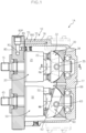
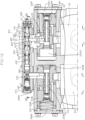
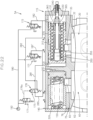
- FIG. 1 is a cross-sectional view of a hydrostatic transmission (HST) 10 in a stepless speed change structure 1A according to the present embodiment.
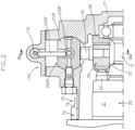
- FIG. 2 shows a cross-sectional view along the line II-II in FIG. 1 .
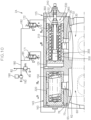
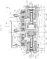
- FIG. 3 shows, at part (a), a cross-sectional view along the IIIA-IIIA line in FIG. 2 , and also shows, at part (b), a cross-sectional view along the line IIIB-IIIB in FIG. 3 .
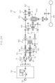
- the stepless speed change structure 1A includes the HST 10 and a speed change operating member (not shown) such as a stepless speed change lever that performs a speed change operation of the HST 10.
- the HST 10 is so configured that the volume of a pump body 20 changes according to an operation of a pump volume adjusting member and the volume of the motor body 50 changes in accordance with an operation of a motor volume adjusting member.
- the HST 10 is of an axial piston type. That is, the HST 10 includes a pump shaft 15 that is driven to rotate around an axis line by a rotational power operatively input from a drive source (not shown), a pump body 20 that is so supported by the pump shaft 15 as to rotate around the axis line together with the pump shaft 15, a pump movable swash plate 30 that acts as the pump volume adjusting member and that changes the volume of the pump body 20 in accordance with a tilting position around a pump swing axis PA, a motor shaft 45 that outputs a rotational power whose rotational speed has been changed in a stepless manner, a motor body 50 so supported by the motor shaft 45 as to rotate together with the motor shaft 45 around an axis line, a motor movable swash plate 60 that acts as the motor volume adjusting member and that changes the volume of the motor body 50 in accordance with the tilting position around a motor swing axis MA, and a pair of
- the pump body 20 includes a pump cylinder block 21 that is supported by the pump shaft 15 in a relatively non-rotatable manner with respect thereto and that has a plurality of cylinder holes placed around the axis line of the pump shaft 15, and a plurality of pump pistons 22 that is housed in the plurality of cylinder holes in a manner to freely move forward and backward and that has free end portions engaged with a swash plate body 32 of the pump movable swash plate 30.
- the motor body 50 has a motor cylinder block 51 that is supported by the motor shaft 45 in a relatively non-rotatable manner with respect thereto and that has a plurality of cylinder holes placed around the axis line of the motor shaft 45, and a plurality of motor pistons 52 that is housed in the plurality of cylinder holes in a manner to freely move forward and backward and that has free end portions engaged with a swash plate body 62 of the motor movable swash plate 60.
- the pump movable swash plate 30 and the motor movable swash plate 60 are cradle-type swash plates.
- the pump movable swash plate 30 and the motor movable swash plate 60 respectively have the swash plate bodies 32, 62 and operation end portions 35, 65.
- the swash plate bodies 32, 62 have piston engaging faces, which engage with the corresponding pump piston 22 and motor piston 52, and back faces opposite the piston engaging faces, wherein the back faces are guided by guide members 38, 68 thereby to enable the swash plate bodies 32, 62 to tilt around the corresponding pump and motor swing axes PA, MA.
- the operation end portions 35, 65 are provided in a manner to tilt around the corresponding pump and motor swing axes PA, MA together with the corresponding swash plate bodies 32, 62.
- the pump movable swash plate 30 and motor movable swash plate 60 can be trunnion-type swash plates.
- the pump movable swash plate and the motor movable swash plate can have swash plate bodies having piston engaging faces that engage with the corresponding pump piston 22 and motor piston 52, and operation end portions (35, 65) that are positioned coaxially with the corresponding pump and motor swing axes PA, MA and that are connected to the swash plate bodies in a manner to tilt the corresponding swash plate bodies around the swing axes in accordance with rotations around the axes.
- the HST 10 is capable of outputting a bidirectional rotational power, which has been speed-changed, from the motor shaft 45. That is, sandwiching a neutral position where the volume of the pump body 20 (discharge amount of the operation oil discharged from the pump body 15 in accordance with one rotation of the pump body 15) is set to zero, the pump volume adjusting member can be operated between a first operating direction movement end that rotates the motor shaft 45 at a forward direction maximum speed and a second operating direction movement end that rotates the motor shaft 45 at a reverse direction maximum speed.
- the pump movable swash plate 30 is used as the pump volume adjusting member.
- a tilting end to one side around the pump swing axis PA (first tilting direction movement end) from the neutral position is the first operating direction movement end
- a tilting end to the other side around the pump swing axis PA (second tilting direction movement end) from the neutral position is the second operating direction movement end.
- the pump volume adjusting member (the pump movable swash plate 30) is positioned in a forward rotation area on the first operating direction side (first tilting direction side) from the neutral position; as the pump volume adjusting member (the pump movable swash plate 30) is operated in the first operating direction (tilted in the first tilting direction) toward the first operating direction movement end (first tilting direction movement end), the discharge amount (forward direction discharge amount) of the operation oil discharged from the pump body 20 in the direction of rotating the motor body 50 in the forward direction increases so that the rotational speed of the motor body 50 (i.e., the motor shaft 45) in the forward rotational direction is increased, meanwhile, as the pump volume adjusting member (the pump movable swash plate 30), in the forward rotation area, is operated in the second operating direction (tilted in the second tilting direction) toward the neutral position, the forward direction discharge amount of the operation oil discharged from the pump body 20 decreases so that the rotational speed of the motor body 50 (i.e., the motor shaft
- the pump volume adjusting member (the pump movable swash plate 30) placed in the forward rotation area is operated in the second operating direction (tilted in the second tilting direction) thereby to be positioned in the neutral position, the discharged amount of the operation oil discharged from the pump body 20 becomes zero so that the rotational speed of the motor body 50 (i.e., the motor shaft 45) becomes zero.
- the pump volume adjusting member (the pump movable swash plate 30) is positioned in a reverse rotation area on the second operating direction side (second tilting direction side) from the neutral position; as the pump volume adjusting member (the pump movable swash plate 30) is operated in the second operating direction (tilted in the second tilting direction) toward the second operating direction movement end (second tilting direction movement end), the discharged amount (reverse direction discharge amount) of the operation oil discharged from the pump body 20 in the direction of rotating the motor body 50 in the reverse direction increases so that the rotational speed of the motor body 50 (i.e., the motor shaft 45) in the reverse rotational direction is increased, meanwhile as the pump volume adjusting member (the pump movable swash plate 30), in the reverse rotation area, is operated in the first operating direction (tilted in the first tilting direction) toward the neutral position, the reverse direction discharge amount of the operation oil discharged from the pump body 20 decreases so that the rotational speed of the motor body 50 (i.e., the motor shaft
- the first tilting direction movement end which is the first operating direction movement end, can be set, for example, by a first tilting direction stop member that, with the pump movable swash plate 30 caused to swing in the first tilting direction (e.g., the forward direction) on one side around the pump swing axis PA, restricts the pump movable swash plate 30 from further swinging to the one side around the pump swing axis PA.
- first tilting direction stop member that, with the pump movable swash plate 30 caused to swing in the first tilting direction (e.g., the forward direction) on one side around the pump swing axis PA, restricts the pump movable swash plate 30 from further swinging to the one side around the pump swing axis PA.
- a pump servo piston 210P that operates and swings the pump movable swash plate 30 is housed, in a bidirectionally slidable manner in first and second servo directions SV1, SV2, within a pump servo space formed in a housing body 75 of an HST housing 70, and the first tilting direction stop member is formed by a portion of the pump servo space that defines a moving end of the pump servo piston 210P in the first servo direction SV1.
- the second tilting direction movement end which is the second operating direction movement end, can be set, for example, by a second tilting direction stop member that, with the pump movable swash plate 30 caused to swing in the second tilting direction (e.g., the reverse direction) on another side around the pump swing axis PA, restricts the pump movable swash plate 30 from further swinging to the other side around the pump swing axis PA.
- the second tilting direction stop member is formed by a portion of the pump servo space that defines a moving end of the pump servo piston 210P in the second servo direction SV2.
- the motor volume adjusting member is operable between a maximum volume position to maximize the volume of the motor body 50 and a minimum volume position to minimize the volume of the motor body 50.
- the motor movable swash plate 60 is used as the motor volume adjusting member.
- the motor movable swash plate 60 is swingable around the motor swing axis MA between the maximum volume position to maximize the volume of the motor body 50 and the minimum volume position to minimize the volume of the motor body 50.
- the minimum volume position can be set, for example, by a minimum volume side stop member that, with the motor movable swash plate 60 caused to swing to one side (e.g., in a smaller volume direction) around the motor swing axis MA, restricts the motor movable swash plate 60 from further swinging to the one side around the motor swing axis MA.
- the motor servo piston 210M that operates and swings the motor movable swash plate 60 is housed, in the bidirectionally slidable manner in a larger volume servo direction SVL and a smaller volume servo direction SVS, within a motor servo space formed in the housing body 75, and the minimum volume side stop member is formed by a portion of the motor servo space that defines a moving end of the motor servo piston 210M in the smaller volume servo direction SVS.
- the maximum volume position can be set, for example, by a maximum volume side stop member that, with the motor movable swash plate 60 caused to swing to another side (e.g., in a larger volume direction) around the motor swing axis MA, restricts the motor movable swash plate 60 from further swinging to the other side around the motor swing axis MA.
- the maximum volume side stop member is formed by a portion of the motor servo space that defines a moving end of the motor servo piston 210M in the larger volume servo direction SVL.
- the operation oil amount required to cause the motor body 50 to make one rotation around the axis increases.
- the motor volume adjusting member (the motor movable swash plate 60) is positioned in the minimum volume position so that the motor body 50 is brought into a minimum volume state, the operation oil amount required to cause the motor body 50 to make one rotation around the axis decreases.
- the HST 10 further has the HST housing 70 that houses therein the pump body 20, the pump movable swash plate 30, the motor body 50, and the motor movable swash plate 60, and that supports the pump shaft 15 and the motor shaft 45 in a rotatable manner around the respective axis lines.
- the HST housing 70 has the housing body 75 provided with an opening through which the pump body 20 and the motor body 50 can be inserted, and a port block 80 so connected to the housing body 75 as to close the opening.
- the housing body 75 has a circumferential wall 76 that surrounds the pump body 20 and the motor body 50, and an end wall 77 that closes one side of the circumferential wall 76 in the axial direction, and the other side of the peripheral wall 76 opposite the end wall 77 is the opening.
- the guide members 38, 68 are respectively placed between the swash plate bodies 32, 62 and the end wall 77.
- the port block 80 is formed with oil paths that forms the pair of HST lines. Further, the port block 80 is formed with a charge oil path 82 (see
- FIG. 1 that forms a charge line for replenishing operation oil to the pair of HST lines.
- the charge oil path 82 has one end portion opening to an outer surface to form a charge port 82P.
- the reference numeral 85 in FIG. 1 is a charge relief valve that sets an oil pressure of the charge line.
- the present invention including the present and the following embodiments can include a radial-piston type HST 10' in place of the axial-piston type HST 10.
- FIG. 4 shows a cross-sectional view of an example of the radial piston type HST 10' applicable to the stepless speed change structure according to the present invention.
- the HST 10' includes a pintle 80' formed with oil paths, a pump shaft 15, a pump body 20', the motor shaft 45, and a motor body 50'.
- the pump body 20' has a pump cylinder 21' with a plurality of cylinder holes, which open radially outwardly, placed around the axis line, and a plurality of pump pistons 22' that is housed in the plurality of cylinder holes in a reciprocating manner to freely move forward and backward.
- the pump cylinder 21' is supported by the pintle 80' in a rotatable manner in a state where the pump cylinder 21' is so connected to the pump shaft 15 as to rotate together with the pump shaft 15 around the axis line.
- the motor body 50' has a motor cylinder 51' with a plurality of cylinder holes, which open radially outward, placed around an axis line, and a plurality of motor pistons 52' that is housed in the plurality of cylinder holes in a reciprocating manner to freely move forward and backward.
- the motor cylinder 51' is supported by the pintle 80' in a rotatable manner in a state where the motor cylinder 51' is so connected to the motor shaft 45 as to rotate together with the motor shaft 45 around the axis line.
- the pintle 80' is formed with a pair of HST lines 90a that fluidly connects the pump body 20' (the pump cylinder 21') with the motor body 50' (the motor cylinder 51').
- the HST 10' further includes a pump movable cam ring 30' that acts as a pump volume adjusting member, and a motor movable cam ring 60' that acts as a motor volume adjusting member.
- the pump movable cam ring 30' has a pump movable cam ring body 32' that has an inner circumferential face, which engages with outer end portions of the plurality of pump pistons 22' in the pump body 20', and that is swingable around a pump swing shaft 39', and an operation end portion 35' that swings the pump movable cam ring body 32' around the pump swing shaft 39'.
- the pump movable cam ring 30' is swingable in a first operating direction on one side and a second operating direction on the other side around the pump swing shaft 39', with sandwiching the neutral position where the central position of the pump movable cam ring body 32' matches the central position of the pump cylinder 21'.
- the motor movable cam ring 60' has a motor movable cam ring body 62' that has an inner circumferential face, which engages with outer end portions of the plurality of motor pistons 52' in the motor body 51', and that is swingable around a motor swing shaft 69', and an operation end portion 65' that swings the motor movable cam ring body 62' around the motor swing shaft 69'.
- the motor movable cam ring 60' is operable, around the motor swing shaft 69', between a minimum volume position that brings the motor body 50' in a minimum volume state, and a maximum volume position that brings the motor body in a maximum volume state.
- the pump swing shaft 39' and the motor swing shaft 69' are formed by a single common shaft.
- the stepless speed change structure 1A further includes a pump operation piston 110, a neutral spring mechanism 120, first and second slide oil chambers 131, 132, a motor operation piston 140, a larger volume operation spring 150, and a smaller volume operating oil chamber 160.
- the pump operation piston 110 is movable bidirectionally in a first slide direction S1 on one side in the axial direction and a second slide direction S2 on the other side in the axial direction, and is operatively connected to the operation end portion of the pump volume adjusting member such that the pump volume adjusting member is operated in the first operating direction in accordance with the movement of the pump operation piston 110 in the first slide direction S1, and at the time point when the pump operation piston 110 is positioned at the first slide direction movement end, the pump volume adjusting member is positioned at the first operating direction movement end, meanwhile the pump volume adjusting member is operated in the second operating direction in accordance with the movement of the pump operation piston 110 in the second slide direction S2, and at the time point where the pump operation piston 110 is positioned at the second slide direction movement end, the pump volume adjusting member is positioned at the second operating direction movement end.
- the HST 10 is of the axial piston type, and has the pump movable swash plate 30 as the pump volume adjusting member.
- a moving end of the pump movable swash plate 30 in the first tilting direction around the pump swing axis PA corresponds to the first operating direction movement end of the pump volume adjusting member, meanwhile a moving end of the pump movable swash plate 30 in the second tilting direction around the pump swing axis PA corresponds to the second operating direction movement end of the pump volume adjusting member.
- the pump operation piston 110 is indirectly connected to the operation end portion of the pump volume adjusting member (in the present embodiment, the operation end portion 35 of the pump movable swash plate 30) via a pump hydraulic servo mechanism 200P.
- the configuration of the pump hydraulic servo mechanism 200P is to be described below.
- the neutral spring mechanism 120 is so configured as to hold the pump operation piston 110 in the neutral position when no external force is added to the pump operation piston 110 meanwhile as to generate a biasing force toward the neutral position when the pump operation piston 110 is moved in the first and second slide directions S1, S2 from the neutral position that corresponds to the neutral position of the pump movable swash plate 30.
- the neutral spring mechanism 120 has first and second slide springs 121, 122 that bias the pump operation pistons 110 in the first and second slide directions S1, S2, respectively.
- the first and second slide springs 121, 122 have biasing forces set in such a manner as to hold the pump operation piston 110 at the neutral position when no external force is added to the pump operation piston 110.
- proximal end sides (opposite sides to distal end sides engaging with the pump operation piston 110) of the first and second slide springs 121, 122 are engaged with position adjusting plugs, and the respective biasing forces can be adjusted by the position adjusting plugs.
- the first and second slide oil chambers 131, 132 are so configured that pressure oil, which has been supplied thereinto, presses and moves the pump operation piston 110 in the first and second slide directions S1, S2, respectively, against the biasing force of the neutral spring mechanism 120.
- the first slide oil chamber 131 is so configured that pressure oil, which has been supplied thereinto, presses and moves the pump operation piston 110 in the first slide direction S1 against the biasing force of the second slide spring 122.
- the second slide oil chamber 132 is so configured that pressure oil, which has been supplied thereinto, presses and moves the pump operation piston 110 in the second slide direction S2 against the biasing force of the first slide spring 121.
- a pump operation piston case 115 which houses therein the pump operation piston 110, is connected to the HST housing 70.
- the pump operation piston case 115 has a housing space that houses therein the pump operation piston 110, and the pump operation piston 110, while defining the first and second slide oil chambers 131, 132, is housed in the housing space in a state of being movable in the first and second slide directions S1, S2.
- the neutral spring mechanism 120 has the first and second slide springs 121, 122, and the first and second slide springs 121, 122 are respectively placed in the first and second slide oil chambers 131, 132.
- the motor operation piston 140 is movable bidirectionally in a smaller volume direction VS on one side and a larger volume direction VL on the other side in the axial direction.
- the motor operation piston 140 is operatively connected to the operation end portion of the motor volume adjusting member such that the motor volume adjusting member is operated in the larger volume direction in accordance with the movement of the motor operation piston 140 in the larger volume direction VL, and is positioned at the maximum volume position in accordance with the positioning of the motor operation piston 140 at the maximum volume position which is a movement end in the larger volume direction VL, meanwhile the motor volume adjusting member is operated in the smaller volume direction in accordance with the movement of the motor operation piston 140 in the smaller volume direction VS, and is positioned at the minimum volume position in accordance with the positioning of the motor operation piston 140 at the minimum volume position which is the movement end in the smaller volume direction VS.
- the HST 10 is of the axial piston type, and has the motor movable swash plate 60 as the motor volume adjusting member.
- a moving end of the motor movable swash plate 60 in the larger volume direction around the motor swing axis MA corresponds to the maximum volume position of the motor volume adjusting member
- a moving end of the motor movable swash plate 60 in the smaller volume direction around the motor swing axis MA corresponds to the minimum volume position of the motor volume adjusting member.
- the motor operation piston 140 is indirectly connected to the operation end portion of the motor volume adjusting member (in the present embodiment, the operation end portion 65 of the motor movable swash plate 60) via a motor hydraulic servo mechanism 200M.
- the configuration of the motor hydraulic servo mechanism 200M is to be described below.
- the larger volume operation spring 150 biases the motor operation piston 140 in the larger volume direction VL toward the maximum volume position which is the initial reference position.
- the maximum volume position of the motor operation piston 140 is a position that causes the motor movable swash plate 60 to be positioned at the maximum volume position.
- the smaller volume operating oil chamber 160 is so configured that pressure oil, which has been supplied thereinto, presses and moves the motor operation piston 140 in the smaller volume direction VS against the biasing force of the larger volume operation spring 150.
- a motor operation piston case 145 which houses therein the motor operation piston 140, is connected to the HST housing 70.
- the motor operation piston case 145 has a housing space that houses therein the motor operation piston 140, and the motor operation piston 140, while defining the smaller volume operating oil chamber 160 and a spring chamber 152 on the opposite side of the smaller volume operating oil chamber 160, is housed in the housing space in an axially bidirectionally movable manner.
- the larger volume operation spring 150 is placed in the spring chamber 152.
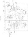
- the stepless speed change structure 1A further includes a first pressure control valve 171 that commonly switches the supplying and discharging of the pressure oil to and from the first slide oil chamber 131 and the smaller volume operating oil chamber 160 according to the operation of the speed change operating member, and a second pressure control valve 172 that switches the supplying and discharging of the pressure oil to and from the second slide oil chamber 132 according to the operation of the speed change operating member.
- the first pressure control valve 171 is so configured as to take a supplying position that supplies the pressure oil from a pressure oil source to both the first slide oil chamber 131 and the smaller volume operating oil chamber 160, and a discharging position that discharges the pressure oil from both the first slide oil chamber 131 and the smaller volume operating oil chamber 160.
- the first pressure control valve 171 is of a depressurizing valve type, and is so configured that as a control current to an electromagnetic solenoid illustrated in FIG. 3 is increased, the oil pressures of the first slide oil chamber 131 and the smaller volume operating oil chamber 160, to which the pressure oil is supplied, increase.
- the second pressure control valve 172 is so configured as to take a supplying position that supplies the pressure oil from the pressure oil source to the second slide oil chamber 132, and a discharging position that discharges the pressure oil from the second slide oil chamber 132.
- the second pressure control valve 172 is also of the depressurizing valve type, and is so configured that as the control current to the electromagnetic solenoid illustrated in FIG. 3 is increased, the oil pressure of the second slide oil chamber 132, to which the pressure oil is supplied, increases.
- the stepless speed change structure 1A further includes a control device (not shown) that, according to the operating state of the speed change operating member, controls the first and second pressure control valves 171, 172.
- the control device for example, based on a signal from an operation position sensor that detects the operating position of the speed change operating member, controls the operation of the first and second pressure control valves 171, 172.
- the biasing forces of the neutral spring mechanism 120 and the larger volume operation spring 150 are set as follows. That is, the biasing forces of the neutral spring mechanism 120 and the larger volume operation spring 150 are so set that, after the pressure oil within the first slide oil chamber 131 causes the pump operation piston 110 to move in the first slide direction S1 so that the neutral spring mechanism 120 is brought into a predetermined retained-elastic state, the pressure oil within the smaller volume operating oil chamber 160 where supply and discharge of the pressure oil is performed in conjunction with the first slide oil chamber 131 causes the motor operation piston 140 to start moving in the smaller volume direction VS while compressing the larger volume operation spring 150.
- the neutral spring mechanism 120 has the first and second slide springs 121, 122, and when the pump operation piston 110 is pressed and moved from the neutral position to the first slide direction S1, the second slide spring 122 is elastically deformed (compressively deformed).
- the biasing forces of the second slide spring 122 and larger volume operation spring 150 are so set that, after the pressure oil within the first slide oil chamber 131 causes the pump operation piston 110 to move in the first slide direction S1 so that the second slide spring 122 is brought into a predetermined compressed state, the pressure oil within the smaller volume operating oil chamber 160 causes the motor operation piston 140 to start moving in the smaller volume direction VS while compressing the larger volume operation spring 150.
- the timing at which the motor operation piston 140 starts to move in the smaller volume direction VS is set as a timing at which the pump operation piston 110 is positioned at the first slide direction movement end, and accordingly, the pump movable swash plate 30 is positioned at the first tilting direction movement end.
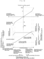
- FIG. 5 shows a graph illustrating a relation among the operating position of the speed change operating member, the output speed of the stepless speed change structure 1A (vehicle traveling speed in a case where the stepless speed change structure 1A is used for a travel system transmission path of a work vehicle), the tilting position of the pump movable swash plate 30, and the tilting position of the motor movable swash plate 60.
- the control device stops the control current to the first and second pressure control valves 171, 172 so as to position the first and second pressure control valves 171, 172 at the discharging position.
- the control device When the speed change operating member is operated from the neutral position to the second operating direction (e.g., backward direction), the control device, while keeping the first pressure control valve 171 at the discharging position, applies the control current to the second pressure control valve 172 in accordance with the operating position of the speed change operating member so as to position the second pressure control valve 172 at the supplying position in accordance with the operating position of the speed change operating member.
- the second operating direction e.g., backward direction
- the pressure oil is supplied from the pressure oil source to the second slide oil chamber 132, and the pump operation piston 110 is pressed and moved in the second slide direction S2 while elastically deforming the neutral spring mechanism 120 (in the present embodiment, while compressing the first slide spring 121).
- the pump movable swash plate 30 is tilted from the neutral position to the second tilting direction, and the speed of the rotational output of the stepless speed change structure 1A is increased in the second direction (e.g. backward direction) from the zero speed to a second direction maximum speed Rmax.
- the control device when the speed change operating member is operated from the neutral position to the first operating direction (e.g., forward direction), the control device, while keeping the second pressure control valve 172 positioned at the discharging position, applies the control current to the first pressure control valve 171 in accordance with the operating position of the speed change operating member to position the first pressure control valve 171 at the supplying position in accordance with the operating position of the speed change operating member.
- the first operating direction e.g., forward direction
- the pressure oil is supplied from the pressure oil source to the first slide oil chamber 131 and the smaller volume operating oil chamber 160, and the pump operation piston 110 receives a pressing force in the first slide direction, meanwhile the motor operation piston 140 receives a pressing force in the smaller volume direction VS.
- the biasing forces of the neutral spring mechanism 120 (in the present embodiment, the second slide spring 132) and the larger volume operation spring 150 are so set that, after the pressure oil within the first slide oil chamber 131 causes the pump operation piston 110 to move in the first slide direction so that the neutral spring mechanism 120 (in the present embodiment, the second slide spring 132) is brought into the predetermined retained-elastic state, the pressure oil within the smaller volume operating oil chamber 160 causes the motor operation piston 140 to start moving in the smaller volume direction VS while compressing the larger volume operation spring 150.
- the predetermined retained-elastic state of the neutral spring mechanism 120 (in the present embodiment, the second slide spring 132) is defined as a state that is realized when the pump operation piston 110 is moved in the first slide direction S1 up to the first slide direction movement end, which causes the pump volume adjusting member to position at the first operating direction movement end (the operating position causing the pump body 20 to have the maximum volume).
- the speed change operating member when the speed change operating member is operated from the neutral position to the motor volume switching start position (the operating position that causes the pump volume adjusting member to position at the first operating direction movement end.
- the speed of the rotational output of the stepless speed change structure 1A is increased from the zero speed to a predetermined speed (first direction intermediate speed Fc) in the first direction (e.g., forward direction).
- the speed change operating member when the speed change operating member is operated in the first operating direction beyond the motor volume switching start position (in the present embodiment, the pump first direction maximum volume position); as the speed change operating member approaches a first operating direction operation end, the pressure oil of the smaller volume operating oil chamber 160 presses and moves the motor operation piston 140 in the smaller volume direction VS against the biasing force of the larger volume operation spring 150. Then, at the time point when the speed change operating member reaches the first operating direction operation end, the motor operation piston 140 is positioned at the minimum volume position at the time point so that the motor movable swash plate 60 is positioned at the minimum volume position. With this, the speed of the rotational output of the stepless speed change structure 1A becomes a first direction maximum speed Fmax.
- the pump movable swash plate 30, with the motor movable swash plate 60 held in the maximum volume position is tilted to the tilting position that corresponds to the operating position of the speed change operating member, thereby making it possible to acquire the output having the desired speed
- the motor movable swash plate 60, with the pump movable swash plate 30 held at the first tilting direction movement end is tilted to the tilting position that corresponds to the operating position of the speed change operating member, thereby making it possible to acquire the output having the desired high speed.
- the timing at which the motor operation piston 140 starts moving in the smaller volume direction is set at the time point when the pump operation piston 110 is positioned at the first slide direction movement end, but the present invention is not limited to the above configuration.
- the biasing force of the neutral spring mechanism 120 (in the present embodiment, the second slide spring 122) and the biasing force of the larger volume operation spring 150 can also be so set that, at the time point when the pump operation piston 110 reaches an arbitrary position before the first slide direction movement end, the motor operation piston 140 starts moving in the smaller volume direction.
- the above setting of the biasing force of the spring can be performed, for example, by replacing the corresponding larger volume operation spring 150 or by changing the thickness of a shim interposed between the proximal end portion of the larger volume operation spring 150 and the spring chamber 152.
- FIG. 6 is a partial cross-sectional view of a stepless speed change structure 1B according to a modified example of the present embodiment, and corresponds to part VI in FIG. 3 .
- the stepless speed change structure 1B has a biasing force adjusting mechanism 155 that adjusts the biasing force of the corresponding larger volume operation spring 150.
- the biasing force adjusting mechanism 155 has a spring receptor 156 that is engageable with a proximal end side of the corresponding larger volume operation spring 150, the spring receptor 156 being configured to have a fixed position in an axial direction that is artificially adjustable from outside.
- the biasing force adjusting mechanism 155 is so configured as to be capable of setting, at the desired value, the biasing force of the corresponding larger volume operation spring 150 by means of the spring receptor 156.
- the reference numeral 157 in FIG. 6 is a lock nut for holding the above spring receptor 156 in the fixed position in the axial direction.
- the present embodiment is so configured that the motor operation piston 140 starts moving in the smaller volume direction after the pump operation piston 110 reaches the first slide direction movement end.
- the pump operation piston 110 i.e., the pump movable swash plate 30
- the motor operation piston 140 i.e., the motor movable swash plate 60
- FIG. 7 shows a graph illustrating a relation among the operating position of the speed change operating member, the output speed of the stepless speed change structure 1A (vehicle traveling speed in a case where the stepless speed change structure 1A is used for the travel system transmission path of a work vehicle), the tilting position of the pump movable swash plate 30, and the tilting position of the motor movable swash plate 60, in a case where the pump operation piston 110 and the motor operation piston 140 are operated in accordance with a different operation pattern (first modified pattern).
- the first modified pattern is so configured that, at the time point when the pump operation piston 110 reaches an arbitrary position before the first slide direction movement end, the motor operation piston 140 starts moving in the smaller volume direction.
- the output of the stepless speed change structure 1A is speed-changed from the second direction maximum speed Rmax via the vehicle traveling speed zero to a first direction first intermediate speed Fc1, as the pump movable swash plate 30, with the motor movable swash plate 60 held in the maximum volume position, is moved in the first tilting direction from the second tilting direction movement end to the first tilting direction intermediate position.
- the output of the stepless speed change structure 1A is speed-changed from the first direction first intermediate speed Fc1 to a first direction second intermediate speed Fc2, as the pump movable swash plate 30 is moved from the first tilting direction intermediate position to the first tilting direction movement end and the motor movable swash plate 60 is moved from the maximum volume position to the intermediate volume position.
- the output of the stepless speed change structure 1A is speed-changed from the first direction second intermediate speed Fc2 to the first direction maximum speed Fmax, as the motor movable swash plate 60, with the pump movable swash plate 30 held at the first tilting direction movement end, is moved from the intermediate volume position to the minimum volume position.
- the tilting operations of the pump movable swash plate 30 and motor movable swash plate 60 are performed continuously without interruption, making it possible to effectively prevent or decrease any jerkiness of the output speed (traveling speed) during the switching transition period.
- FIG. 8 shows a graph illustrating a relation among the operating position of the speed change operating member, the output speed of the stepless speed change structure 1A (vehicle traveling speed in a case where the stepless speed change structure 1A is used for the travel system transmission path of a work vehicle), and the tilting position of the pump movable swash plate 30, and the tilting position of the motor movable swash plate 60, in a case where the pump operation piston 110 and the motor operation piston 140 are operated in accordance with still another operation pattern (second modified pattern).
- the second modified pattern is so configured that, at the time point when the pump operation piston 110 reaches an arbitrary position before the first slide direction movement end, the motor operation piston 140 starts moving in the smaller volume direction.
- the second modified example shown in FIG. 8 performs a speed change operation similar to that of the first modified example shown in FIG. 7 .
- the biasing forces of the neutral spring mechanism 120 and the larger volume operation spring 150 are so set that, when the speed change operating member is operated between the second operating direction operation end and the motor volume switching start position; with the motor operation piston 140 held in the maximum volume position thereby to keep the motor movable swash plate 60 positioned in the maximum volume position, the pump operation piston 110 is pressed and moved in the first slide direction S1 thereby to tilt the pump movable swash plate 30 in the first tilting direction as the speed change operating member is operated in the first operating direction, and the pump operation piston 110 is positioned in the intermediate position before the first slide direction movement end thereby to have the pump movable swash plate 30 positioned at the first tilting direction intermediate position before the first tilting direction movement end at the time point when the speed change operating member reaches the motor volume switching start position.
- the second modified example shown in FIG. 8 performs a speed change operation different from that of the first modified example shown in FIG. 7 .
- the pump movable swash plate 30 is positioned at the first tilting direction movement end and the motor movable swash plate 60 is positioned at the minimum volume position.
- the output of the stepless speed change structure 1A is speed-changed from the second direction maximum speed Rmax via the vehicle speed zero to the first direction first intermediate speed Fc1, as the pump movable swash plate 30, with the motor movable swash plate 60 held in the maximum volume position, is moved in the first tilting direction from the second tilting direction movement end to the first tilting direction intermediate position. Then, the output of the stepless speed change structure 1A is accelerated from the first direction first intermediate speed Fc1 to the first direction maximum speed Fmax as the pump movable swash plate 30 is moved from the first tilting direction intermediate position to the first tilting direction movement end and the motor movable swash plate 60 is moved from the maximum volume position to the minimum volume position.
- the tilting operations of the pump movable swash plate 30 and motor movable swash plate 60 are performed continuously without interruption, making it possible to effectively prevent or decrease any jerkiness of the output speed (traveling speed) during the switching transient period.
- the pump hydraulic servo mechanism 200P includes the pump servo piston 210P, first and second servo oil chambers 220P1, 220P2, and a pump servo switching valve 230P.
- the pump servo piston 210P is movable bidirectionally in the first servo direction SV1 on one side in the axial direction and the second servo direction SV2 on the other side in the axial direction, and is engaged with the operation end portion 35 of the pump movable swash plate 30 such that the pump movable swash plate 30 is tilted in the first and second tilting directions respectively around the pump swing axis PA in accordance with the movements in the first and second servo directions SV1, SV2.
- the first and second servo oil chambers 220P1, 220P2 are so configured that the pressure oil, which has been supplied into the first and second servo oil chambers 220P1, 220P2, presses and moves the pump servo piston 210P in the first and second servo directions SV1, SV2, respectively.
- the housing body 75 is formed with a pump servo space, and the pump servo piston 210P, while defining the first and second servo oil chambers 220P1, 220P2, is housed in the pump servo space in a manner to be movable bidirectionally in the first and second servo directions SV1, SV2.
- the pump servo switching valve 230P takes a holding position, a first servo position, and a second servo position.
- the pump servo switching valve 230P is so configured as to guide the pressure oil from the pressure oil source to the first servo oil chamber 220P1 and discharge the pressure from of the second servo oil chamber 220P2 when positioned at the first servo position, as to discharge the pressure oil from the first servo oil chamber 220P1 and to guide the pressure oil from the pressure oil source to the second servo oil chamber 220P2 when positioned at the second servo position, and as to close the first and second servo oil chambers 220P1, 220P2 when positioned at the holding position.
- the pump servo switching valve 230P is operatively connected to the pump operation piston 110 in a manner to take the first and second slide directions S1, S2, respectively, according to the movements of the pump operation piston 110 in the first and second slide directions S1, S2.
- the pump servo piston 210P is formed with a central hole along the axial direction, and the pump servo switching valve 230P, in a state of being connected to the pump operation piston 110 via a pump connecting rod 250P inserted into an access opening formed in the pump servo piston 210P, is housed in the central hole in a manner to be axially bidirectionally movable.
- the pump servo switching valve 230P is linked to the pump operation piston 110 via the pump connecting rod 250P.
- the motor hydraulic servo mechanism 200M includes a motor servo piston 210M, a larger volume servo spring 240M, a smaller volume servo oil chamber 220M, and a motor servo switching valve 230M.
- the motor servo piston 210M is movable bidirectionally in the smaller volume servo direction SVS on one side in the axial direction and in the larger volume servo direction SVL on the other side in the axial direction.
- the motor servo piston 210M is engaged with the operation end portion 65 of the motor movable swash plate 60 such that, the motor servo piston 210M tilts the motor movable swash plate 60 in the smaller volume direction around the motor swing axis MA as being moved in the smaller volume servo direction SVS, and positions the motor movable swash plate 60 at the minimum volume position when positioned at the predetermined minimum volume servo position, meanwhile the motor servo piston 210M tilts the motor movable swash plate 60 in the larger volume direction around the motor swing axis MA as being moved in the larger volume servo direction SVL, and positions the motor movable swash plate 60 at the maximum volume position when positioned in the predetermined maximum volume servo position.
- the larger volume servo spring 240M biases the motor servo piston 210M in the larger volume servo direction SVL toward the maximum volume servo position.
- the smaller volume servo oil chamber 220M is so configured that the pressure oil, which has been supplied into the smaller volume servo oil chamber 220M, presses and moves the motor servo piston 210M in the smaller volume servo direction SVS against the biasing force of the larger volume servo spring 240M.
- the housing body 75 is formed with the pump servo space, and the motor servo piston 210M, while defining the smaller volume servo oil chamber 220M and a spring chamber 245 placed axially opposite to the smaller volume servo oil chamber 220M, is housed in the motor servo space in a manner to be movable bidirectionally in the smaller volume servo direction SVS and the larger volume servo direction SVL.
- the larger volume servo spring 240M is housed in the spring chamber 245.
- the motor servo switching valve 230M takes a holding position, a smaller volume position, and a larger volume position.
- the motor servo switching valve 230M is so configured as to guide the pressure oil from the pressure oil source to the smaller volume servo oil chamber 220M and discharge the pressure oil from the spring chamber 245 when positioned at the smaller volume position, as to discharge the pressure oil from the smaller volume servo oil chamber 220M and to guide the pressure oil from the pressure oil source to the spring chamber 245 when positioned at the larger volume position, and as to close the smaller volume servo oil chamber 220M and the spring chamber 245 when positioned at the holding position.
- the motor servo switching valve 230M is operatively connected to the motor operation piston 140 in such a manner as to take the larger volume position and the smaller volume position, respectively, according to the movement of the motor operation piston 140 in the larger volume direction VL and smaller volume direction VS.
- the motor servo piston 210M is formed with a central hole along the axial direction, and the motor servo switching valve 230M, in a state of being connected to the motor operation piston 140 via a motor connecting rod 250M inserted into an access opening formed in the motor servo piston 210M, is housed in the central hole in a manner to be axially bidirectionally movable.
- the motor servo switching valve 230M is linked to the motor operation piston 140 via the motor connecting rod 250M.
- the pressure oil for pressing and moving the pump operation piston 110 and the motor operation piston 140 is taken out of the charge line.
- FIG. 9 shows a hydraulic circuit diagram of the stepless speed change structure 1A.
- the stepless speed change structure 1A has a pressure oil supply line 180 having a proximal end side fluidly connected to the charge line (the charge oil path 82), a first supply-discharge line 181 having a distal end side fluidly connected to the first slide oil chamber 131 and the smaller volume operating oil chamber 160, and a second supply-discharge line 182 having a distal end side fluidly connected to the second slide oil chamber 132.
- the first pressure control valve 171 is so configured as to cause the first supply-discharge line 181 to be fluidly connected to the pressure oil supply line 180 when positioned at the supplying position, and as to cause the first supply-discharge line 181 to drain when positioned at the discharging position.
- the second pressure control valve 172 is so configured as to cause the second supply-discharge lines 182 to be fluidly connected to the pressure oil supply line 180 when positioned at the supplying position, and as to cause the second supply-discharge line 182 to drain when positioned in the discharging position.
- the pressure oil supplied to the pump hydraulic servo mechanism 200P and the motor hydraulic servo mechanism 200M is also taken out of the charge line (the charge oil path 82).
- the stepless speed change structure 1A has a pump servo line 185P that fluidly connects the pressure oil supply line 180 to an inlet port of the pump servo switching valve 230P, and a motor servo line 185M that fluidly connects the pressure oil supply line 180 to an inlet port of the motor servo switching valve 230M.
- FIG. 10 is a partial cross-sectional view of a stepless speed change structure 2A according to the present embodiment, showing a cross-sectional view that corresponds to part (a) in FIG. 3 in the first embodiment.
- the same member as in the first embodiment is to be marked with the same reference numeral, and any description thereof is to be appropriately omitted.
- the stepless speed change structure 2A according to the present embodiment is different from the stepless speed change structure 1A according to the first embodiment mainly in that the pump hydraulic servo mechanism 200P and the motor hydraulic servo mechanism 200M are deleted, and that the pump operation piston 110 and the motor operation piston 140 are changed to a pump operation piston 310 and a motor operation piston 320.
- the pump operation piston 310 is mechanically connected to the operation end portion 35 of the pump movable swash plate 30 in such a manner as to tilt the pump movable swash plate 30 in the first and second tilting directions around the pump swing axis PA, respectively, in accordance with the movements of the pump operation piston 310 in the first and second slide directions S1, S2.
- the motor operation piston 320 is mechanically connected to the operation end portion 65 of the motor movable swash plate 60 in such a manner as to tilt the motor movable swash plate 60 in the smaller volume direction and larger volume direction around the motor swing axis MA, respectively, in accordance with the movements of the motor operation piston 320 in the smaller volume direction VS and the larger volume direction VL.
- the stepless speed change structure 2A Compared to the stepless speed change structure 1A, the stepless speed change structure 2A according to the present embodiment has a neutral spring mechanism 330 in place of the neutral spring mechanism 120 (the first and second slide springs 121, 122).
- the pump operation piston 310 is different from the pump operation piston 110 in that the pump operation piston 310 has a hollow portion along the first and second slide directions S1, S2.
- the neutral spring mechanism 330 includes a support rod 340 that extends along the first and second slide directions S1, S2 and that is supported by the pump operation piston case 115 so that a distal side of the support rod 340 enters the hollow portion, a distal side spring receptor 350 and a proximal side spring receptor 360 that are supported on a distal side and a proximal side of the support rod 340, respectively, so as to be placed in the hollow portion and to be axially movable relative to the support rod 340, a distal side stopper 355 so provided on the support rod 340 as to define a distal side movement end of the tip side spring receptor 350 relative to the support rod 340, a proximal side stopper 365 so provided on the support rod 340 as to define a proximal side movement end of the proximal side spring receptor 360 relative to the support rod 340, and a single biasing spring 370 having a distal side engaged with the distal side spring receptor 350 and a proximal side engaged with
- the pump operation piston 310 together with the distal side spring receptor 350 is pressed and moved in the direction (corresponding to the first slide direction S1 in the present embodiment) that expands the oil chamber placed on the distal side of the support rod 340 (the first slide oil chamber 131) and contracts the opposite side oil chamber (the second slide oil chamber 132).
- the proximal side spring receptor 360 is stopped from moving to the proximal side of the support rod 340 by the proximal side stopper 365; therefore, as the pump operation piston 310 is pressed and moved to the direction (in the present embodiment, the first slide direction S1) that expands the oil chamber placed on the distal side of the support rod 340 and contracts the opposite side oil chamber, the retained elasticity amount (compression amount) of the single biasing spring 370 is increased.
- the biasing forces of the single biasing spring 370 and the larger volume operation spring 150 are so set that, after the movement of the pump operation piston 310 in the first slide direction S1 brings the single biasing spring 370 into a predetermined retained-elastic state, and then the pressure oil of the smaller volume operating oil chamber 160 causes the motor operation piston 320 to start moving in the smaller volume direction VS while elastically deforming the larger volume operation spring 150.
- the pump operation piston case 115 and the motor operation piston case 145 are integrally formed.
- the reference numeral 190 in FIG. 10 is a drive source
- the reference numeral 192 is a hydraulic pump that is driven by the drive source 190 and discharges the pressure oil to the charge line.
- FIG. 11 is a partial cross-sectional view of a stepless speed change structure 3A according to the present embodiment, showing a cross-sectional view that corresponds to FIG. 2 in the first embodiment.
- FIG. 12 shows a cross-sectional view along the Line XII-XII in FIG. 11 .
- FIG. 13 shows a cross-sectional view along the line XIII-XIII in FIG. 12 .
- the same member as in the first and second embodiments is to be marked with the same reference numerals, and any description thereof is to be appropriately omitted.
- the stepless speed change structure 3A includes the HST 10, a speed change operating member 410, the pump hydraulic servo mechanism 200P, a pump operation connecting mechanism 430, and a motor operation connecting mechanism.
- the speed change operating member 410 is operable bidirectionally around the axis between a first operating direction operation end D1max on one side around the axis and a second operating direction maximum operating position D2max on the other side around the axis, sandwiching a neutral position N.
- the speed change operating member 410 includes an operating shaft 412 that is rotatable around an axis, and an operating arm 414 connected to the operating shaft 412 in such a manner that an external operation to the operating arm 414 can rotate the operating shaft 412 around the axis.
- the pump operation connecting mechanism 430 has a pump spool 450 that is movable in the first slide direction S1 on one side and in the second slide direction S2 on the other side in the axial direction.
- the motor operation connecting mechanism has a motor spool 480 that is placed coaxially in series on one side of the pump spool 450 in the axial direction and that is movable bidirectionally in the smaller volume direction VS on one side and the larger volume direction VL on the other side in the axial direction, a larger volume operation spring 490 that biases the motor spool 480 in the larger volume direction VL, and a motor spool maximum volume position setting member 495 that directly or indirectly sets the motor spool maximum volume position, which is defined by a movement end of the motor spool 480 in the larger volume direction VL.
- the motor operation connecting mechanism is so configured as to tilt the motor movable swash plate 60 in the smaller volume direction on one side and in the larger volume direction on the other side around the motor swing axis MA, respectively, in accordance with the movements of the motor spool 480 in the smaller volume direction VS and larger volume direction VL.
- a spool case 500 having a spool housing space that houses therein the pump spool 450 and the motor spool 480 integrally is connected to the HST housing 70.
- the operating shaft 412 having an inner end portion extending into a space provided in a portion where the spool case 500 is connected with the HST housing 70 and having an outer end portion extending outward, is supported by the spool case 500.
- the pump operation connecting mechanism 430 has the pump hydraulic servo mechanism 200P.
- the pump hydraulic servo mechanism 200P is so configured as to tilt the pump movable swash plate 30 in the first and second tilting directions in accordance with the operations of the speed change operating member 410 in the first and second operating directions D1, D2.
- the pump hydraulic servo mechanism 200P is operatively connected to the speed change operating member 410 so as to have the pump movable swash plate 30 positioned at the neutral position N in accordance with the operation of the speed change operating member 410 to the neutral position N, and so as to have the pump movable swash plate 30 tilted in the first and second tilting directions in accordance with the operations of the speed change operating member 410 to the first and second operating directions D1, D2.
- the pump operation connecting mechanism 430 further includes an interlocking arm 432 connected to an inner end portion of the operating shaft 412, and a pump servo engaging pin 435 provided on a free end side of the interlocking arm 432 and engaged with the pump servo switching valve 230P via the access opening formed in the pump servo piston 210P.
- the interlocking arm 432 and the pump servo engaging pin 435 are placed in the space provided in the portion where the spool case 500 is connected with the HST housing 70.
- the pump servo engaging pin 435 is engaged with the pump servo switching valve 230P in such a manner as to have the pump servo switching valve 230P positioned at a first servo position when the speed change operating member 410 is operated in the first operating direction D1, and as to have the pump servo switching valve 230P positioned at a second servo position when the speed change operating member 410 is operated in the second operating direction D2.
- the pump spool 450 is operatively connected to the speed change operating member 410 in such a manner as to take a pump spool neutral position in accordance with the operation of the speed change operating member 410 to the neutral position N, and as to move from the pump spool neutral position to the first slide direction movement end on one side in the axial direction and the second slide direction movement end on the other side in the axial direction, respectively, in accordance with the operations of the speed change operating member 410 from the neutral position N to the first and second operating direction operation ends D1max, D2max.
- the pump operation connecting mechanism 430 further includes a pump spool engaging pin 440 that has a proximal end portion connected to the interlocking arm 432 and a distal end portion engaged with the pump spool 450.
- the pump spool engaging pin 440 is engaged with the pump spool 450 in such a manner as to have the pump spool 450 positioned at the pump spool neutral position in accordance with the operation of the speed change operating member 410 to the neutral position N, as to move the pump spool 450 from the pump spool neutral position to the first slide direction movement end in accordance with the operation of the speed change operating member 410 from the neutral position N to the first operating direction operation end D1max, and as to move the pump spool 450 from the pump spool neutral position to the second slide direction movement end in accordance with the operation of the speed change operating member 410 from the neutral position N to the second operating direction maximum operating position D2max.
- the pump spool 450 has a first spool 451 that is pressed and moved in the first slide direction S1 via the pump engaging pin 440 when the speed change operating member 410 is operated from the neutral position N to first operating direction D1, and a second spool 452 that is separate from the first spool 451 and that is pressed and moved in the second slide direction S2 when the speed change operating member 410 is operated from the neutral position N to the second operating direction D2.
- the stepless speed change structure 3A has a neutral spring mechanism 460 that directly or indirectly holds the pump spool 450 at the pump spool neutral position when no external force is applied to the pump spool 450, and that generates a biasing force for directly or indirectly pressing the pump spool 450 toward the pump spool neutral position when the pump spool 450 is moved from the pump spool neutral position to the first and second slide directions S1, S2.
- the neutral spring mechanism 460 has a support rod 462 that has a shaft portion 463 so supported by the spool case 500 as to extend along the slide direction in the slide range of the pump spool 450, a first slide spring 471 that biases the second spool 452 in the first slide direction S1, and a second slide spring 472 that biases the first spool 451 in the second slide direction S2.
- the spool case 500 is formed with a through hole extending in the slide direction of the pump spool 450, and first and second lid members 511, 513 close the through hole's pump spool 450 side and the through hole's motor spool 480 side, respectively, thereby to form the spool housing space.
- the support rod 462 has, in addition to the shaft portion 463, a middle engaging portion 465 that is provided in the middle between the distal side and proximal side of the shaft portion 463 and that is larger in diameter than the shaft portion 463, and a distal engaging portion 467 that is provided on the distal side of the support rod 462 and that is larger in diameter than the shaft portion 463.
- the first and second spools 451, 452 are externally supported on the shaft portion 463 on both sides in the axial direction.
- the first spool 451 is externally supported on the shaft portion 463 in a manner to be movable in an axial direction.
- the second spool 452 is externally supported on the shaft portion 463 in a manner to be movable in an axial direction.
- the second slide spring 472 is interposed between the distal engaging portion 467 and the first spool 451, thereby to bias the first spool 451 in the second slide direction S2 toward the middle engaging portion 465.
- the first slide spring 471 is interposed between the first lid member 511 and the middle engaging portion 465, thereby to bias the second spool 452 in the first slide direction S1 toward the middle engaging portion 465.
- the pump spool 450 moves as follows in accordance with the operation of the speed change operating member 410.
- cancelling an operating force to the speed change operating member 410 or operating the speed change operating member 410 in the second operating direction D2 returns the first spool 451 to the second slide direction S2 by means of the biasing force of the second slide spring 472 by the amount that corresponds to the operation amount of the speed change operating member 410 in the second operating direction D2.
- the neutral spring mechanism 460 is so configured as to directly bias the pump spool 450 to the pump spool neutral position.
- the neutral spring mechanism 460 can be modified to bias the speed change operating member 410 to the neutral position N thereby to indirectly bias the pump spool 450 to the pump spool neutral position.
- the pump spool 450 is formed by a single member, and the pump engaging pin 440 is connected to the single pump spool 450 such that the single pump spool 450 moves in the first and second slide directions S1, S2 in accordance with the operations of the speed change operating member 410 in the first and second operating directions D1, D2, respectively.
- the motor spool 480 is coaxially placed in series on one side of the pump spool 450 in the axial direction, and is movable bidirectionally in the smaller volume direction VS on one side and the larger volume direction VL on the other side in the axial direction.
- the motor spool 480 is coaxially positioned on one side of the pump spool 450 in the axial direction.
- the larger volume operation spring 490 biases the motor spool 480 in the larger volume direction VL.
- the larger volume operation spring 490 is placed between the motor spool 480 and the second lid member 513.
- the motor spool maximum volume position setting member 495 directly or indirectly sets the spool maximum volume position, which is defined by the moving end of the motor spool 480 in the larger volume direction.
- the support rod 462 of the neutral spring mechanism 460 is commonly used as the motor spool maximum volume position setting member 495.
- the motor spool 480 which is biased in the larger volume direction VL by means of the larger volume operation spring 490, engages with the tip engaging portion 467 of the support rod 462, thereby to define the motor spool maximum volume position.
- the motor operation connecting mechanism further has the motor hydraulic servo mechanism 200M.
- the motor hydraulic servo mechanism 200M is so configured as to tilt the motor movable swash plate 60 in the smaller volume direction on one side and the larger volume direction on the other side around the motor swing axis MA in accordance with the movements of the motor spool 480 in the smaller volume direction VS and the larger volume direction VL, respectively.
- the motor servo switching valve 230M is so connected to the motor spool 480 as to take the smaller volume position and the larger volume position, respectively, in accordance with the movements of the motor spool 480 in the larger volume direction VL and the smaller volume direction VS.
- a flexible portion 520 that allows the pump spool 450 to move by a predetermined distance in the first slide direction S1 with the motor spool 480 held at the motor spool maximum volume position.
- the axial length of the flexible portion 520 is so set that, when the pump spool 450, via the pump hydraulic servo mechanism 200P, is positioned to a slide position that have the pump movable swash plate 30 positioned at the first tilting direction movement end, the pump spool 450 is positioned at an end of the flexible portion 520 (i.e., so that the pump spool 450 contacts the motor spool 480).
- the pump operation connecting mechanism 430 is so configured that, at the time point when the speed change operating member 410 is operated from the neutral position N to the first operating direction D1 thereby to reach the motor volume switching start position (in the present embodiment, the pump first direction maximum volume position P1max) before reaching the first operating direction operation end D1max, the pump spool 450 moves to the slide position where the pump spool 450, via the pump hydraulic servo mechanism 200P, has the pump movable swash plate 30 positioned at the first tilting direction movement end.
- the motor volume switching start position in the present embodiment, the pump first direction maximum volume position P1max
- the axial length of flexible portion 520 is so set that, at this time point, the pump spool 450 contacts the motor spool 480.
- FIG. 14 shows cross-sectional views of the pump spool 450, the motor spool 480, the pump hydraulic servo mechanism 200P, and the motor hydraulic servo mechanism 200M.
- the part (a) of FIG. 14 shows a state where the pump spool 450 is moved in the first slide direction S1 from the pump spool neutral position to the slid position where the pump spool 450 contacts the motor spool 480.
- the part (b) of FIG. 14 shows a state where, passing the flexible portion 520, the pump spool 450 together with the motor spool 480 has been moved in the first slide direction S1 (for the motor spool 480, in the smaller volume direction VS).
- the speed change operating member 410 is operable between the first operating direction operation end D1max and the second operating direction operation end D2max; and when the speed change operating member 410 is positioned at the neutral position N between the first operating direction operation end D1max and the second operating direction operation end D2max, the pump hydraulic servo mechanism 200P neutrally operates via the pump operation connecting mechanism 430, thereby to have the pump movable swash plate 30 positioned at the neutral position (see FIG. 12 ).
- the pump servo switching valve 230P moves in the direction that corresponds to the second operating direction D2, thereby creating a state of pressure oil supply to the second servo oil chamber 220P2, pressing and moving the pump servo piston 210P in the second servo direction SV2, and tilting the pump movable swash plate 30 in the second tilting direction.
- the pump servo switching valve 230P and the pump servo piston 210P return to the relative neutral state so that the first and second servo oil chambers 220P1, 220P2 are closed. Accordingly, the pump servo piston 210P holds the pump movable swash plate 30 at a tilting position where the pump movable swash plate 30 is positioned at that point.
- the above operation tilts the pump movable swash plate 30 in the second tilting direction in accordance with the operation of the speed change operating member 410; and when the speed change operating member 410 is positioned at the second operating direction operation end D2max, the pump movable swash plate 30 is positioned at the second tilting direction movement end.
- the pump spool 450 does not contact the motor spool 480, and the motor spool 480 remains held at the motor spool maximum volume position by the larger volume operation spring 490.
- the motor movable swash plate 60 is held at the maximum volume position.
- the pump servo switching valve 230P and the pump servo piston 210P return to the relative neutral state so that the first and second servo oil chambers 220P1, 220P2 are closed. Accordingly, the pump servo piston 210P holds the pump movable swash plate 30 at a tilting position where the pump movable swash plate 30 is positioned at that point.
- the above operation tilts the pump movable swash plate 30 in the first tilting direction in accordance with the operation of the speed change operating member 410 in the first operating direction D1, and at the time point when the speed change operating member 410 is positioned at the pump first direction maximum volume position P1max, the pump movable swash plate 30 is positioned at the first tilting direction movement end.
- the pump spool 450 is positioned at the end of the flexible portion 520. Therefore, at this time point, the motor spool 480 does not receive any pressing force from the pump spool 450, and remains held at the motor spool maximum volume position by the larger volume operation spring 490. Thus, the motor movable swash plate 60 is held at the maximum volume position.
- the pump servo piston 210P is positioned at the first slide direction movement end that have the pump movable swash plate 30 positioned at the first tilting direction movement end.
- the pump servo switching valve 230P When the speed change operating member 410 is operated further in the first operating direction D1 from the state where the speed change operating member 410 is positioned at the pump first direction maximum volume position P1max; relative to the pump servo piston 210P in a state of being positioned at the first slide movement end, the pump servo switching valve 230P, from being at the relative neutral state, moves in the direction that corresponds to the first operating direction D1, thereby creating the state of pressure oil supply to the first servo oil chamber 220P1.
- the pump servo piston 210P is positioned at the first slide direction movement end, the pump servo piston 210P is not moved any further in the first servo direction SV1; as a result, when the speed change operating member 410 is operated between the pump first direction maximum volume position P1max and the first operating direction operation end D1max, the pump movable swash plate 30 is held at the first tilting direction movement end (the part (b) in FIG. 14 ).
- the pump spool 450 is positioned in the area beyond the flexible portion 520 by the pump operation connecting mechanism 430, and the pump spool 450 together with the motor spool 480 is positioned at the position that corresponds to the operating position of the speed change operating member 410.
- the pump spool 450 in accordance with the operating position of the speed change operating member 410, moves together with the motor spool 480 that is biased in the larger volume direction VL by the larger volume operation spring 490.
- Such movement of the motor servo switching valve 230M causes a relative displacement of the motor servo switching valve 230M with respect to the motor servo piston 210M, moving the motor servo piston 210M in the corresponding direction so that the motor movable swash plate 60 is mover to the tilting position that corresponds to the operating position of the speed change operating member 410.
- FIG. 15 is a partial cross-sectional view of a stepless speed change structure 4A according to the present embodiment, showing a cross-sectional view that corresponds to FIG. 3 in the first embodiment.
- FIG. 16 shows a hydraulic circuit diagram of the stepless speed change structure 4A.
- the same members as in the former embodiments are denoted with the same reference numerals, and any description thereof is to be appropriately omitted.
- the motor movable swash plate 60 is moved when the pump movable swash plate 30 is moved to the first tilting direction movement end or to near the first tilting direction movement end, meanwhile the motor movable swash plate 60 is fixed at the initial position (larger volume position) even when the pump movable swash plate 30 is moved to the second tilting direction movement end or to near the second tilting direction movement end.
- the stepless speed change structure 4A is so configured that, in addition to when the pump movable swash plate 30 is moved to the first tilting direction movement end or to near the first tilting direction movement end, the motor movable swash plate 60 is moved when the pump movable swash plate 30 is moved to the second tilting direction movement end or to near the second tilting direction movement end.
- the stepless speed change structure 4A includes the HST 10, the speed change operating member (not shown in FIGS. 15 and 16 ), the pump operation piston 110, the neutral spring mechanism 120, the first and second slide oil chambers 131, 132, the motor operation piston 140, the larger volume operation spring 150, the smaller volume operating oil chamber 160, the first pressure control valve 171, the second pressure control valve 172, a flow path switching valve 175, and the control device (also not shown in FIGS. 15 and 16 ).
- the first pressure control valve 171 is so configured as to take a supplying position that supplies, to the first slide oil chamber 131, the pressure oil from the pressure oil source, and a discharging position that discharges the pressure oil from the first slide oil chamber 131.
- the second pressure control valve 172 is so configured as to take a supplying position that supplies, to the second slide oil chamber 132, the pressure oil from the pressure oil source, and a discharging position that discharges the pressure oil from the second slide oil chamber 132.
- the stepless speed change structure 4A includes the pressure oil supply line 180, a first supply-discharge line 181' fluidly connected to the first slide oil chamber 131, and the second supply-discharge line 182.
- the first pressure control valve 171 is so configured, when positioned at the supplying position, as to fluidly connect the first supply-discharge line 181' to the pressure oil supply line 180, and when positioned at the discharging position, as to cause the first supply-discharge line 181' to drain.
- the second pressure control valve 172 is so configured, when positioned at the supplying position, as to fluidly connect the second supply-discharge line 182 to the pressure oil supply line 180, and when positioned at the discharging position, as to cause the second supply-discharge line 182 to drain.
- the flow path switching valve 175 is so configured as to take a first position that introduces the pressure oil of the first slide oil chamber 131 into the smaller volume operating oil chamber 160, and a second position that introduces the pressure oil of the second slide oil chamber 132 into the smaller volume operating oil chamber 160.
- the stepless speed change structure 4A includes a first slide line 281 directly or indirectly fluidly connected to the first slide oil chamber 131, a second slide line 282 directly or indirectly fluidly connected to the second slide oil chamber 132, and a smaller volume line 285 fluidly connected to the smaller volume operating oil chamber 160.
- the flow path switching valve 175 is so configured, when positioned at the first position, as to fluidly connect the smaller volume line 285 to the first slide line 281, and when positioned at the second position, as to fluidly connect the smaller volume line 285 to the second slide line 282.
- the first pressure control valve 171, the second pressure control valve 172 and the flow path switching valve 175 are operatively controlled by the control device as follows.
- the control device When recognizing, based on a signal from the operation position sensor, that the speed change operating member is positioned in the operation area that causes the output rotational direction of the stepless speed change structure 4A to be in the forward rotational direction (i.e., forward operation area), the control device has the flow path switching valve 175 positioned at the first position. This creates a state where the smaller volume operating oil chamber 160 is pressure-controlled in conjunction with the first slide oil chamber 131.
- the control device when recognizing, based on the signal from the operation position sensor, that the speed change operating member is positioned in the operation area that causes the output rotational direction of the stepless speed change structure 4A to be in the reverse rotational direction (i.e., reverse operation area), the control device has the flow path switching valve 175 positioned at the second position. This creates a state where the smaller volume operating oil chamber 160 is pressure-controlled in conjunction with the second slide oil chamber 132.
- the flow path switching valve 175 includes a pilot-type switching valve 176 that can selectively take the first position and the second position, and a solenoid switching valve 177 that is position-controlled by the control device.
- the pilot-type switching valve 176 is biased by a spring or the like toward one of the first and second positions (the first position in FIG. 15 ), and is so configured as to take one of the first and second positions in the initial state where no pilot pressure is received, and as to take the other of the first and second positions (the second position in FIG. 15 ) when the pilot pressure is received.
- the solenoid switching valve 177 can selectively take an operating position that supplies the pilot pressure to the pilot-type switching valve 176, and an initial position that shuts off the pilot pressure supply to the pilot-type switching valve 176.
- the solenoid switch valve 177 is so configured, when positioned at the operating position, as to supply the pressure oil from the pressure oil supply line 180 to a pilot line 176a of the pilot-type switching valve 176, and when positioned at the initial position, as to shut off the supply of the pressure oil to the pilot line 176a.
- the control device when the speed change operating member is positioned in the forward operating area, the control device does not send a control signal to the solenoid switching valve 177, and the solenoid switching valve 177 remains at the initial position. Accordingly, the pilot-type switching valve 176 is placed at the first position so that the smaller volume operating oil chamber 160 is in a state of being pressure-controlled in conjunction with the first slide oil chamber 131.
- the control device sends the control signal to the solenoid switching valve 177, and the solenoid switching valve 177 is positioned at the operating position. Accordingly, the pilot-type switching valve 176 receives the pilot pressure and is positioned at the second position so that the smaller volume operating oil chamber 160 is in a state of being pressure controlled in conjunction with the second slide oil chamber 132.
- FIG. 17 shows a partial cross-sectional view of a stepless speed change structure 4B, which has the flow path switching valve 175' formed with the single solenoid switching valve, according to a first modified example of the present embodiment.
- the flow path switching valve 175' is so configured as to selectively take, in accordance with the operating position of the speed change operating member, a first position that fluidly connects the smaller volume line 285 to the first slide line 281, and a second position that fluidly connects the smaller volume line 285 to the second slide line 282.
- the control device when the speed change operating member is positioned in the forward operating area, the control device has the flow path switching valve 175' positioned at the first position, thereby to create a state where the smaller volume operating oil chamber 160 is pressure-controlled in conjunction with the first slide oil chamber 131.
- the control device When the speed change operating member is positioned in the reverse operating area, the control device has the flow path switching valve 175' positioned at the second position, thereby to create a state where the smaller volume operating oil chamber 160 is pressure-controlled in conjunction with the second slide oil chamber 132.
- the pump movable swash plate 30 and the motor movable swash plate 60 are moved as the following manner.
- FIG. 18 shows a graph illustrating a relation, in the stepless speed change structure 4A, among the operating position of the speed change operating member, the tilting position of the pump movable swash plate 30, the tilting position of the motor movable swash plate 60, and the output speed of the stepless speed change structure 4A.
- the stepless speed change structure 4A is so configured so that, when the speed change operating member is operated in a middle area between a second operating direction motor volume switching start position before the second operating direction operation end and a first operating direction motor volume switching start position before the first operating direction operation end, the first and second operating direction motor volume switching start positions sandwiching the neutral position, the pump operation piston 110, with the motor operation piston 140 hold at the maximum volume position thereby to hold the motor movable swash plate 60 at the maximum volume position, is positioned at the position that corresponds to the operating position of the speed change operating member so that the pump movable swash plate 30 is positioned at the corresponding tilting position.
- the pump operation piston 110 is pressed and moved in the first slide direction S1 thereby to move the pump movable swash plate 30 in the first tilting direction.
- the biasing forces of the neutral spring mechanism 120 and the larger volume operation spring 150 are so set that, at the time point when the speed change operating member is operated in the first operating direction to reach a first operating direction motor volume switching start position, the pump operation piston 110, with the motor operation piston 140 kept positioned at the maximum volume position, is positioned at the first slide direction movement end so that the pump movable swash plate 30 is moved to the first tilting direction movement end.
- the output of the stepless speed change structure 4A has the speed (first direction intermediate speed Fc) that is acquired when the pump movable swash plate 30 is positioned at the first tilting direction movement end with motor movable swash plate 60 positioned at the maximum volume position (see FIG. 18 ).
- the motor operation piston 140 When the speed change operating member is operated in the area between the first operating direction motor volume switching start position and the first operating direction operation end; the motor operation piston 140, with the pump operation piston 110 held at the first slide direction movement end thereby to keep the pump movable swash plate 30 positioned at the first operating direction movement end, is pressed and moved in the smaller volume direction VS in accordance with the operation of the speed change operating member in the first operating direction so that the motor movable swash plate 60 moved accordingly in the smaller volume direction.
- the biasing force of the larger volume operation spring 150 is so set that, at the time point when the speed change operating member is positioned at the first operating direction operation end, the motor operation piston 140 is positioned at the minimum volume position thereby to move the motor movable swash plate 60 to the minimum volume position.
- the output of the stepless speed change structure 4A has the speed (first direction maximum speed Fmax) that is acquired when the pump movable swash plate 30 is positioned at the first tilting direction movement end and the motor movable swash plate 60 is positioned at the minimum volume position (see FIG. 18 ).
- the pump operation piston 110 is pressed and moved in the second slide direction S2 thereby to move the pump movable swash plate 30 in the second tilting direction.
- the pump operation piston 110 is positioned at the second slide direction movement end thereby to move the pump movable swash plate 30 to the second tilting direction movement end.
- the output of the stepless speed change structure 4A has the speed (second direction intermediate speed Rc) that is acquired when the pump movable swash plate 30 is positioned at the second tilting direction movement end with the motor movable swash plate 60 positioned at the maximum volume position (see FIG. 18 ).
- the motor operation piston 140 When the speed change operating member is operated in the area between the second operating direction motor volume switching start position and the second operating direction operation end; the motor operation piston 140, with the pump operation piston 110 held at the second slide direction movement end thereby to keep the pump movable swash plate 30 positioned at the second operating direction movement end, is pressed and moved in the smaller volume direction VS in accordance with the operation of the speed change operating member in the second operating direction D2 so that the motor movable swash plate 60 is moved accordingly in the smaller volume direction.
- the motor operation piston 140 is positioned at the minimum volume position thereby to move the motor movable swash plate 60 to the minimum volume position.
- the output of the stepless speed change structure 4A has the speed (second direction maximum speed Rmax) that is acquired when the pump movable swash plate 30 is positioned at the second tilting direction movement end and the motor movable swash plate 60 is positioned at the minimum volume position (see FIG. 18 ).
- the pump operation piston 110 i.e., the pump movable swash plate 30
- the motor operation piston 140 i.e., the motor movable swash plate 60
- FIG. 19 shows a graph illustrating a relation among the operating position of the speed change operating member, the tilting position of the pump movable swash plate 30, the tilting position of the motor movable swash plate 60, and the output speed of the stepless speed change structure 4A, in a case where the pump operation piston 110 and the motor operation piston 140 are operated in accordance with a different operation pattern (first modified pattern).
- the first modified pattern is common to the operation pattern in the present embodiment in that, when the speed change operating member is operated in the middle area, the pump operation piston 110, with motor operation piston 140 positioned at the maximum volume position thereby to keep the motor movable swash plate 60 held at the maximum volume position, has the pump movable swash plate 30 positioned at the tilting position that corresponds to the operating position of the speed change operating member.
- the first modified pattern is different from the operation pattern in the present embodiment in the tilting position of the pump movable swash plate 30 that is acquired when the speed change operating member is positioned at the first operating direction motor volume switching start position and the second operating direction motor volume switching start position.
- the biasing forces of the neutral spring mechanism 120 and the larger volume operation spring 150 are so set that, at the time point when the speed change operating member is operated in the first operating direction to reach the first operating direction motor volume switching start position, the pump operation piston 110, with the motor operation piston 140 kept positioned at the maximum volume position, is positioned at a first slide direction intermediate position before the first slide direction movement end thereby to have the pump movable swash plate 30 positioned at the first tilting direction intermediate position.
- the output of the stepless speed change structure 4A has the speed (first direction first intermediate speed Fc1) that is acquired when the pump movable swash plate 30 is positioned at the first tilting direction intermediate position and the motor movable swash plate 60 is positioned at the maximum volume position.
- the pump operation piston 110 is positioned at the first slide direction movement end thereby to have the pump movable swash plate 30 positioned at the first tilting direction movement end.
- the biasing force of the larger volume operation spring 150 is so set that, at this time point, the motor operation piston 140 is positioned at the intermediate volume position between the maximum volume position and the minimum volume position thereby to have the motor movable swash plate 60 positioned at the intermediate volume position between the maximum volume position and the minimum volume position.
- the output of the stepless speed change structure 4A has the speed (first direction second intermediate speed Fc2) that is acquired when the pump movable swash plate 30 is positioned at the first tilting direction movement end and the motor movable swash plate 60 is positioned at the intermediate volume position (see FIG. 19 ).
- the motor operation piston 140 When the speed change operating member is operated in the area between the first operating direction pump maximum volume position and the first operating direction operation end; the motor operation piston 140, with the pump operation piston 110 held at the first slide direction movement end thereby to keep the pump movable swash plate 30 positioned at the first operating direction movement end, is pressed and moved in the smaller volume direction in accordance with the operation of the speed change operating member in the first operating direction thereby to accordingly move the motor movable swash plate 60 in the smaller volume direction.
- the motor operation piston 140 is positioned at the minimum volume position thereby to move the motor movable swash plate 60 to the minimum volume position.
- the output of the stepless speed change structure 4A has the speed (first direction maximum speed Fmax) that is acquired when the pump movable swash plate 30 is positioned at the first tilting direction movement end and the motor movable swash plate 60 is positioned at the minimum volume position (see FIG. 19 ).
- the pump operation piston 110 is pressed and moved in the second slide direction S1 thereby to move the pump movable swash plate 30 in the second tilting direction.
- the pump operation piston 110 is positioned at the second slide direction intermediate position before the second slide direction movement end thereby to have the pump movable swash plate 30 positioned at the second tilting direction intermediate position.
- the output of the stepless speed change structure 4A has the speed (second direction first intermediate speed Rc1) that is acquired when the pump movable swash plate 30 is set in the second tilting direction intermediate position and the motor movable swash plate 60 is set in the maximum volume position (see FIG. 19 ).
- the pump operation piston 110 is positioned at the second slide direction movement end thereby to have the pump movable swash plate 30 positioned at the second tilting direction movement end.
- the motor operation piston 140 is positioned at the intermediate volume position between the maximum volume position and the minimum volume position, thereby to have the motor movable swash plate 60 positioned at the intermediate volume position between the maximum volume position and the minimum volume position.
- the output of the stepless speed change structure 4A has the speed (second direction second intermediate speed Rc2) that is acquired when the pump movable swash plate 30 is positioned at the second tilting direction movement end and the motor movable swash plate 60 is positioned at the intermediate volume position (see FIG. 19 ).
- the motor operation piston 140 is positioned at the minimum volume position thereby to move the motor movable swash plate 60 to the minimum volume position.
- the output of the stepless speed change structure 4A has the speed (second direction maximum speed Rmax) that is acquired when the pump movable swash plate 30 is positioned at the second tilting direction movement end and the motor movable swash plate 60 is positioned at the minimum volume position.
- FIG. 20 shows a graph illustrating a relation among the operating position of the speed change operating member, the tilting position of the pump movable swash plate 30, the tilting position of the motor movable swash plate 60, and the output speed of the stepless speed change structure 4A, in a case where the pump operation piston 110 and the motor operation piston 140 are operated in another different operation pattern (second modified pattern).
- the second modified pattern is common to the first modified pattern in that, when the speed change operating member is operated in the middle area, the pump operation piston 110, with the motor operation piston 140 holding the motor movable swash plate 60 at the maximum volume position, moves the pump movable swash plate 30 in accordance with the operating position of the speed change operating member, and also in that, at the time point when the speed change operating member reaches the first and second operating direction motor volume switching start positions, the pump movable swash plate 30 is respectively positioned at the first and second tilting direction intermediate positions.
- the second modified pattern is different from the first modified pattern at the timing when the pump movable swash plate 30 is positioned at the first and second tilting direction movement ends.
- the biasing forces of the neutral spring mechanism 120 and the larger volume operation spring 150 are so set that, when the speed change operating member is operated in the area between the first operating direction motor volume switching start position and the first operating direction operation end, as the speed change operating member is operated in the first operating direction, the pump operation piston 110 is pressed and moved in the first slide direction S1 thereby to move the pump movable swash plate 30 toward the first tilting direction movement end, and the motor operation piston 140 is pressed and moved in the smaller volume direction thereby to move the motor movable swash plate 60 toward the minimum volume position, and at the time point when the speed change operating member is positioned at the first operating direction operation end, the pump operation piston 110 is positioned at the first slide direction movement end thereby to have the pump movable swash plate 30 positioned at the first tilting direction movement end, and the motor operation piston 140 is positioned at the minimum volume position thereby to have the motor movable swash plate 60 positioned at the minimum volume position.
- the output of the stepless speed change structure 4A controlled in accordance with the in the second modified pattern has
- the pump operation piston 110 is positioned at the second slide direction movement end thereby to have the pump movable swash plate 30 positioned at the second tilting direction movement end, and the motor operation piston 140 is positioned at the minimum volume position thereby to have the motor movable swash plate 60 positioned at the minimum volume position.
- the output of the stepless speed change structure 4A has the speed (second direction maximum speed Rmax) that is acquired when the pump movable swash plate 30 is positioned at the second tilting direction movement end and the motor movable swash plate 60 is positioned at the minimum volume position (see FIG. 20 ).
- the stepless speed change structure 4A according to the present embodiment can also include the biasing force adjusting mechanism 155.
- FIG. 21 shows a partial cross-sectional view of a stepless speed change structure 4C, which includes the biasing force adjusting mechanism 155, according to a second modified example of the present embodiment.
- Providing the biasing force adjusting mechanism 155 makes it easy to adjust the timing at which the pump movable swash plate 30 starts moving (tilting) and the timing at which the motor movable swash plate 60 starts moving (tilting).
- FIG. 22 shows a partial cross-sectional view of a stepless speed change structure 5A according to the present embodiment, which corresponds to FIG. 15 in the fourth embodiment.
- the same members as in the former embodiments are to be denoted with the same reference numerals, and any description thereof is to be appropriately omitted.
- the stepless speed change structure 5A according to the present embodiment is different from the stepless speed change structure 4A according to the fourth embodiment mainly in that, the pump hydraulic servo mechanism 200P and the motor hydraulic servo mechanism 200M are deleted, and that the pump operation piston 110 and the motor operation piston 140 are changed to the pump operation piston 310 and the motor operation piston 320.
- the pump operation piston 310 and the motor operation piston 320 are mechanically connected to the operation end portion 35 of the pump movable swash plate 30 and the operation end portion 65 of the motor movable swash plate 60, respectively.
- the stepless speed change structure 5A has the neutral spring mechanism 330 in place of the neutral spring mechanism 120 (the first and second slide springs 121, 122).
- the stepless speed change structure 5Acan also include the biasing force adjusting mechanism 155.
- FIG. 23 shows a partial cross-sectional view of a stepless speed change structure 5B according to a modified example of the present embodiment, which includes the biasing force adjusting mechanism 155.
- FIG. 24 shows a transmission schematic diagram of a work vehicle 100 to which a stepless speed change structure 6A according to the present embodiment is applied.
- FIGS. 25 and 26 show, respectively, a partial cross-sectional view and a hydraulic circuit diagram of the stepless speed change structure 6A.
- the same members as in the former embodiments are to be denoted with the same reference numerals, and any description thereof is to be appropriately omitted.
- the stepless speed change structure 6A is interposed in the travel system transmission path from the drive source 190 to a drive wheel 690 in the work vehicle 100.
- the reference numerals 660 and 665 in FIG. 24 are a forward/reverse switching mechanism and a sub-speed change mechanism, respectively, which are inserted in the above travel system transmission path.
- the reference numeral 600 is a PTO (power take off) shaft
- the reference numerals 610 and 620 are a PTO clutch mechanism and a PTO speed change mechanism, respectively, which are inserted in the PTO system transmission path from the drive source 190 to the PTO shaft 600.
- the stepless speed change structure 6A includes the HST 10, a planetary gear mechanism 300, the speed change operating member, the pump operation piston 110, the second slide direction spring 122, the first slide oil chamber 131, the larger volume operation spring 150, the smaller volume operating oil chamber 160, the first pressure control valve 171, and the control device that controls the operation of the first pressure control valve 171.
- the planetary gear mechanism 300 includes a sun gear 302, a planetary gear 304 that meshes with the sun gear 302, an internal gear 306 that meshes with the planetary gear 304, and a carrier 308 that supports the planetary gear 304 in a rotatable manner around an axis and that rotates around an axis of the sun gear 302 in conjunction with a revolution of the planetary gear 304 around the sun gear 302, wherein the sun gear 302, the carrier 308 and the internal gear 306 form three planetary elements.
- the planetary gear mechanism 300 is configured so that a first element out of the three planetary elements receives a reference rotational power operatively transmitted from the drive source 190, a second element received an HST output operatively transmitted from the motor shaft 45, and a third element outputs a combined rotational power combining the reference rotational power and the HST output.
- the internal gear 306 acts as the first element
- the sun gear 302 acts as the second element
- the carrier 308 acts as the third acting.
- FIG. 27 shows a relation, in the stepless speed change structure 6A, among the operating position of the speed change operating member, the tilting position of the pump movable swash plate 30, the tilting position of the motor movable swash plate 60, and the output speed of the stepless speed change structure 6A (that is, the rotational speed of the combined rotational power output from the third element of the planetary gear mechanism 300).
- the gear ratio of the planetary gear mechanism 300 is so set that, when the pump movable swash plate 30 is positioned at the second tilting direction movement end (e.g., reverse direction movement end) so that the HST output to be input into the second element has the second operating direction highest speed (e.g., the reverse direction highest speed), the combined rotational power output from the third element (i.e., output of the stepless speed change structure 6A) has zero speed, and that as the pump movable swash plate 30 is operated from the second tilting direction movement end via the neutral position to the first tilting direction movement end (e.g., the forward direction movement end), the rotational speed of the combined rotational power (i.e., output of the stepless speed change structure 6A) is increased in one direction.
- the second tilting direction movement end e.g., reverse direction movement end
- the first pressure control valve 171 supplies and discharges the pressure oil to and from the first slide oil chamber 131 and the smaller volume operating oil chamber 160 integrally.
- the stepless speed change structure 6A has the pressure oil supply line 180 fluidly connected to the pressure oil source, and the first supply-discharge line 181 fluidly connected to the first slide oil chamber 131 and the smaller volume operating oil chamber 160.
- the first pressure control valve 171 is so configured, in accordance with a control signal from the control device, as to selectively take a supplying position to cause the first supply-discharge line 181 to be fluidly connected to the pressure oil supply line 180, and a discharging position to cause the first supply-discharge line 181 to drain.
- the stepless speed change structure 6A further includes the pump hydraulic servo mechanism 200P that moves the pump movable swash plate 30 in accordance with the movement of the pump operation piston 110, and the motor hydraulic servo mechanism 200M that moves the motor movable swash plate 60 in accordance with the movement of the motor operation piston 140.
- the stepless speed change structure 6A includes the biasing force adjusting mechanism 155.
- the biasing forces of the second slide spring 122 and larger volume operation spring 150 are so set that, after the pump operation piston 110 is positioned at the first slide direction movement end thereby to have the pump movable swash plate 30 positioned at the first tilting direction movement end, the motor operation piston 140 then starts sliding in the smaller volume direction VS thereby to move the motor movable swash plate 60 in the smaller volume direction.
- the stepless speed change structure 6A having the above configuration operates as follows. As shown in FIG. 27 and described above, when the speed change operating member is positioned at the second operating direction operation end so that the pump operation piston 110 is positioned at the second slide direction movement end thereby to have the pump movable swash plate 30 positioned at the second tilting direction movement end, the combined rotational power output from the planetary gear mechanism 300 (the output of the stepless speed change structure 6A) has zero speed.
- the pump operation piston 110 When the speed change operating member is operated in the area, sandwiching the neutral position (a position to make the HST 10's output zero speed), between the second operating direction operation end and the motor volume switching start position before the first operating direction operation end, the pump operation piston 110, with the motor operation piston 140 held at the maximum volume position thereby to hold the motor movable swash plate 60 at the maximum volume position, is pressed and moved in the first slide direction S1 from the second slide direction movement end to the first slide direction movement end in accordance with the operation of the speed change operating member in the first operating direction from the second operating direction operation end to the motor volume switching start position thereby to accordingly move the pump movable swash plate 30 from the second tilting direction movement end to the first tilting direction movement end.
- the combined rotational power of the planetary gear mechanism 300 (the output of the stepless speed change structure 6A) is accelerated from the zero speed to the intermediate speed Fc (see FIG. 27 ).
- the motor operation piston 140 When the speed change operating member is operated between the motor volume switching start position and the first operating direction operation end; the motor operation piston 140, with the pump operation piston 110 held at the first slide direction movement end thereby to keep the pump movable swash plate 30 positioned at the first operating direction movement end, is pressed and moved in the smaller volume direction VS from the maximum volume position to the minimum volume position in accordance with the operation of the speed change operating member in the first operating direction from the motor volume switching start position to the first operating direction operation end thereby to accordingly move the motor movable swash plate 60 from the maximum volume position to the minimum volume position.
- the combined rotational power of the planetary gear mechanism 300 (the output of the stepless speed change structure 6A) is accelerated from the intermediate speed Fc to the maximum speed Fmax (see FIG. 27 ).
- the pump operation piston 110 i.e., the pump movable swash plate 30
- the motor operation piston 140 i.e., the motor movable swash plate 60
- FIG. 28 shows a graph illustrating a relation among the operating position of the speed change operating member, the tilting position of the pump movable swash plate 30, the tilting position of the motor movable swash plate 60, and the output speed of the stepless speed change structure 6A, in a case where the pump operation piston 110 and the motor operation piston 140 are operated in accordance with a different operation pattern (first modified pattern).
- the first modified pattern is common to the operation pattern in the present embodiment in that, when the speed change operating member is operated in the area between the second operating direction operation end and the motor volume switching start position, the pump operation piston 110, with the motor operation piston 140 positioned at the maximum volume position thereby to keep the motor movable swash plate 60 held at the maximum volume position, has the pump movable swash plate 30 positioned at the tilting position that corresponds to the operating position of the speed change operating member.
- the first modified pattern is different from the operation pattern in the present embodiment in the tilting position of the pump movable swash plate 30 at the time when the speed change operating member is positioned at the motor volume switching start position.
- the biasing forces of the second slide spring 122 and larger volume operation spring 150 are so set that,
- the combined rotational power of the planetary gear mechanism 300 (the output of the stepless speed change structure 6A) is accelerated from zero speed to the first direction first intermediate speed Fc1 (see FIG. 28 ).
- the combined rotational power of the planetary gear mechanism 300 (the output of the stepless speed change structure 6A) is accelerated from the first intermediate speed Fc1 to the second intermediate speed Fc2 (see FIG. 28 ).
- the combined rotational power of the planetary gear mechanism 300 (the output of the stepless speed change structure 6A) is accelerated from the second intermediate speed Fc2 to the maximum speed Fmax (see FIG. 28 ).
- FIG. 29 shows a graph illustrating a relation among the operating position of the speed change operating member, the tilting position of the pump movable swash plate 30, the tilting position of the motor movable swash plate 60, and the output speed of the stepless speed change structure 6A, in a case where the pump operation piston 110 and the motor operation piston 140 are operated in accordance with another different operation pattern (second modified pattern).
- the second modified pattern is common to the first modified pattern in that, when the speed change operating member is operated in the area between the second operating direction operation end and the motor volume switching start position, the pump operation piston 110, with the motor operation piston 140 positioned at the maximum volume position thereby to keep the motor movable swash plate 60 held at the maximum volume position, has the pump movable swash plate 30 positioned at the tilting position that corresponds to the operating position of the speed change operating member, and also in that, at the time point when the speed change operating member reaches the motor volume switching start position, the pump movable swash plate 30 is positioned at the first tilting direction intermediate position.
- the second modified pattern is different from the first modified pattern at the timing when the pump movable swash plate 30 is positioned at the first tilting direction movement end.
- the biasing forces of the second slide spring 122 and larger volume operation spring 150 are so set that,
- the combined rotational power of the planetary gear mechanism 300 (the output of the stepless speed change structure 6A) is accelerated from zero speed to the intermediate speed Fc (see FIG. 29 ).
- the combined rotational power of the planetary gear mechanism 300 (the output of the stepless speed change structure 6A) is accelerated from the intermediate speed Fc1 to the maximum speed Fmax (see FIG. 29 ).
- FIG. 30 is a partial cross-sectional view of a stepless speed change structure 7A according to the present embodiment, showing a cross-sectional view that corresponds to FIG. 25 in the sixth embodiment.
- the same members as in the former embodiments are to be denoted with the same reference numerals, and any description thereof is to be appropriately omitted.
- the stepless speed change structure 7A according to the present embodiment is different from the stepless speed change structure 6A according to the sixth embodiment mainly in that, the pump hydraulic servo mechanism 200P and the motor hydraulic servo mechanism 200M are deleted, and that the pump operation piston 110 and the motor operation piston 140 are changed to the pump operation piston 310 and the motor operation piston 320.
- the pump operation piston 310 and the motor operation piston 320 are mechanically connected to the operation end portion 35 of the pump movable swash plate 30 and the operation end portion 65 of the motor movable swash plate 60, respectively.
- the stepless speed change structure 7A has the neutral spring mechanism 330 in place of the neutral spring mechanism 120 (the first and second slide springs 121, 122).
Landscapes
- Engineering & Computer Science (AREA)
- General Engineering & Computer Science (AREA)
- Mechanical Engineering (AREA)
- Physics & Mathematics (AREA)
- Fluid Mechanics (AREA)
- Control Of Fluid Gearings (AREA)
Claims (28)
- Struktur (1A-1B, 2A) zur stufenlosen Drehzahländerung, aufweisend ein hydrostatisches Getriebe (10) und ein Drehzahländerungs-Betätigungselement, wobei das hydrostatische Getriebe (10) eine Verstell-Hydraulikpumpe aufweist, die so eingerichtet ist, dass sich ein Volumen eines Pumpenkörpers (20) gemäß einer Betätigung eines Pumpenvolumen-Verstellelements (30) ändert, und einen Verstell-Hydraulikmotor aufweist, der so eingerichtet ist, dass sich ein Volumen eines Motorkörpers (50) gemäß einer Betätigung eines Motorvolumen-Verstellelements (60) ändert, und wobei das Drehzahländerungs-Betätigungselement dafür eingerichtet ist, einen Drehzahländerungszustand des hydrostatischen Getriebes (10) zu ändern, wobei die Struktur (1A-1B, 2A) zur stufenlosen Drehzahländerung umfasst:einen Pumpenbetätigungskolben (110, 310), der bidirektional in einer ersten und einer zweiten Gleitrichtung (S1, S2) auf einer Seite und auf der anderen Seite in einer axialen Richtung beweglich ist und der direkt oder indirekt mit einem Betätigungsendabschnitt (35) des Pumpenvolumen-Verstellelements (30) im Eingriff steht, dergestalt, dass Bewegungen des Pumpenbetätigungskolbens (110, 310) in der ersten und der zweiten Gleitrichtung bewirken, dass das Pumpenvolumen-Verstellelement (30) in der ersten bzw. der zweiten Betätigungsrichtung betätigt wird;einen Neutral-Federmechanismus (120, 330), der den Pumpenbetätigungskolben (110, 310) an einer neutralen Position hält, wenn keine äußere Kraft an den Pumpenbetätigungskolben (110, 310) angelegt wird, und eine Vorspannkraft in Richtung der neutralen Position generiert, wenn der Pumpenbetätigungskolben (110, 310) aus der neutralen Position in die erste und die zweite Gleitrichtung (S1, S2) bewegt wird;eine erste und eine zweite Gleitölkammer (131, 132), die so eingerichtet sind, dass dort hineingeleitetes Drucköl den Pumpenbetätigungskolben (110, 310) entgegen der Vorspannkraft des Neutral-Federmechanismus (120, 330) in die erste bzw. die zweite Gleitrichtung (S1, S2) drückt und bewegt;einen Motorbetätigungskolben (140, 320), der bidirektional in einer Richtung eines kleineren Volumens (VS) auf einer Seite und in einer Richtung eines größeren Volumens (VL) auf der anderen Seite in einer axialen Richtung beweglich ist, und der direkt oder indirekt mit einem Betätigungsendabschnitt (65) des Motorvolumen-Verstellelements (60) im Eingriff steht, dergestalt, dass Bewegungen des Motorbetätigungskolbens (140, 320) in der Richtung eines kleineren Volumens (VS) und in der Richtung eines größeren Volumens (VL) bewirken, dass das Motorvolumen-Verstellelement (60) in einer Richtung eines kleineren Volumens bzw. in einer Richtung eines größeren Volumens betätigt wird;eine Betätigungsfeder (150) eines größeren Volumens, die den Motorbetätigungskolben (140, 320) in die Richtung eines größeren Volumens (VL) vorspannt; undeine Betätigungsölkammer (160) eines kleineren Volumens, die so eingerichtet ist, dass dort hineingeleitetes Drucköl den Motorbetätigungskolben (140, 320) entgegen der Vorspannkraft der Betätigungsfeder (150) eines größeren Volumens in die Richtung eines kleineren Volumens (VS) drückt und bewegt;dadurch gekennzeichnet, dass die Struktur (1A-1B, 2A) zur stufenlosen Drehzahländerung des Weiteren umfasst:ein erstes Drucksteuerungsventil (171), das das Zuführen und Ablassen von Drucköl zu bzw. aus der ersten Gleitölkammer (131) und der Betätigungsölkammer (160) eines kleineren Volumens gemäß der Betätigung des Drehzahländerungs-Betätigungselements gemeinsam schaltet;ein zweites Drucksteuerungsventil (172), das das Zuführen und Ablassen von Drucköl in die bzw. aus der zweiten Gleitölkammer (132) gemäß der Betätigung des Drehzahländerungs-Betätigungselements schaltet;wobei Vorspannkräfte des Neutral-Federmechanismus (120, 330) und der Betätigungsfeder (150) eines größeren Volumens so eingestellt sind, dass, nachdem Drucköl innerhalb der ersten Gleitölkammer (131) den Pumpenbetätigungskolben (110, 310) veranlasst, sich in der ersten Gleitrichtung (S1) zu bewegen, dergestalt, dass der Neutral-Federmechanismus (120, 330) in einen zuvor festgelegten zurückgehalten-elastischen Zustand gebracht wird, Drucköl innerhalb der Betätigungsölkammer (160) eines kleineren Volumens den Motorbetätigungskolben (140, 320) veranlasst, mit einer Bewegung in einer Richtung eines kleineren Volumens (VS) zu beginnen, während die Betätigungsfeder (150) eines größeren Volumens zusammengedrückt wird.
- Struktur (1A-1B, 2A) zur stufenlosen Drehzahländerung nach Anspruch 1, wobei der Neutral-Federmechanismus (120, 330) zu dem Zeitpunkt in den zuvor festgelegten zurückgehalten-elastischen Zustand gebracht wird, an dem der Pumpenbetätigungskolben (110, 310) das Pumpenvolumen-Verstellelement (30) am Ende einer Bewegung in einer ersten Betätigungsrichtung positioniert hat.
- Struktur (1A-1B, 2A) zur stufenlosen Drehzahländerung nach Anspruch 1, wobei der Neutral-Federmechanismus (120, 330) zu dem Zeitpunkt in den zuvor festgelegten zurückgehalten-elastischen Zustand gebracht wird, an dem der Pumpenbetätigungskolben (110, 310) das Pumpenvolumen-Verstellelement (30) an einer zuvor festgelegten Position vor einem Ende einer Bewegung in einer ersten Betätigungsrichtung positioniert hat.
- Struktur (1A-1B, 2A) zur stufenlosen Drehzahländerung nach Anspruch 3, wobei die Vorspannkräfte des Neutral-Federmechanismus (120, 330) und der Betätigungsfeder (150) eines größeren Volumens so eingestellt sind, dass der Motorbetätigungskolben (140, 320) veranlasst, dass das Motorvolumen-Verstellelement (60) zu dem Zeitpunkt, an dem der Pumpenbetätigungskolben (110, 310) veranlasst, dass das Pumpenvolumen-Verstellelement (30) am Ende einer Bewegung in einer ersten Betätigungsrichtung positioniert wird, am Ende einer Bewegung in einer Richtung eines kleineren Volumens positioniert wird.
- Struktur (1A-1B, 2A) zur stufenlosen Drehzahländerung nach Anspruch 3, wobei die Vorspannkräfte des Neutral-Federmechanismus (120, 330) und der Betätigungsfeder (150) eines größeren Volumens so eingestellt sind, dass der Motorbetätigungskolben (140, 320) veranlasst, dass das Motorvolumen-Verstellelement (60) zu dem Zeitpunkt, an dem der Pumpenbetätigungskolben (110, 310) veranlasst, dass das Pumpenvolumen-Verstellelement (30) am Ende einer Bewegung in einer ersten Betätigungsrichtung positioniert wird, an einer zuvor festgelegten Position vor einem Ende einer Bewegung in einer Richtung eines kleineren Volumens positioniert wird.
- Struktur (1A-1B, 2A) zur stufenlosen Drehzahländerung nach einem der Ansprüche 1 bis 5, des Weiteren umfassend:eine erste Zufuhr-Ablassleitung (181), die mit der ersten Gleitölkammer (131) und der Betätigungsölkammer (160) eines kleineren Volumens in Strömungsverbindung steht; undeine zweite Zufuhr-Ablassleitung (182), die mit der zweiten Gleitölkammer (132) in Strömungsverbindung steht, wobei wobei das erste Drucksteuerungsventil (171) in der Lage ist, eine Zufuhrposition einzunehmen, die die erste Zufuhr-Ablassleitung (181) mit einer Beschickungsleitung (82) zum Nachfüllen von Betätigungsöl in das hydrostatische Getriebe (10) in Strömungsverbindung setzt, und eine Ablassposition einzunehmen, in der die erste Zufuhr-Ablassleitung (181) abgelassen wird, undwobei das zweite Drucksteuerungsventil (172) in der Lage ist, eine Zufuhrposition einzunehmen, die die zweite Zufuhr-Ablassleitung (182) mit der Beschickungsleitung (82) in Strömungsverbindung setzt, und eine Ablassposition einzunehmen, in der die zweite erste Zufuhr-Ablassleitung (181) abgelassen wird.
- Struktur (1A-1B) zur stufenlosen Drehzahländerung nach einem der Ansprüche 1 bis 6, des Weiteren umfassend:einen hydraulischen Pumpen-Servomechanismus (200P), der das Pumpenvolumen-Verstellelement (30) gemäß der Bewegung des Pumpenbetätigungskolbens (110) hydraulisch betätigt, undeinen hydraulischen Motor-Servomechanismus (200M), der das Motorvolumen-Verstellelement (60) gemäß der Bewegung des Motorbetätigungskolbens (140) hydraulisch betätigt.
- Struktur (1A-1B) zur stufenlosen Drehzahländerung nach Anspruch 7, wobeider hydraulische Motor-Servomechanismus (200M) einen Motor-Servokolben (210M), eine Servofeder (240M) eines größeren Volumens, eine Federkammer (245), in der die Servofeder (240M) eines größeren Volumens aufgenommen ist, eine Servoölkammer (220M) eines kleineren Volumens, und ein Motor-Servoschaltventil (230M) umfasst,der Motor-Servokolben (210M) bidirektional in einer Servorichtung eines kleineren Volumens (SVS) auf einer Seite und in einer Servorichtung eines größeren Volumens (SVL) auf der anderen Seite in einer axialen Richtung gemäß einer Schaltbewegung des Motor-Servoschaltventils (230M) bewegt wird und mit dem Endabschnitt (65) des Motorvolumen-Verstellelements (60) im Eingriff steht, dergestalt, dass der Motor-Servokolben (210M) das Motorvolumen-Verstellelement (60) in der Richtung eines kleineren Volumens betätigt, wenn er in der Servorichtung eines kleineren Volumens (SVS) bewegt wird, und das Motorvolumen-Verstellelement (60) an der Position eines minimalen Volumens positioniert, wenn er an einer Servoposition eines minimalen Volumens positioniert ist, während der Motor-Servokolben (210M) das Motorvolumen-Verstellelement (60) in der Richtung eines größeren Volumens betätigt, wenn er in der Servorichtung eines größeren Volumens (SVL) bewegt wird, und das Motorvolumen-Verstellelement (60) an der Position eines maximalen Volumens positioniert, wenn er an einer Servoposition eines maximalen Volumens positioniert ist,die Servofeder (240M) eines größeren Volumens den Motor-Servokolben (210M) in die Servorichtung eines größeren Volumens (SVL) drückt,die Servoölkammer (220M) eines kleineren Volumens so eingerichtet ist, dass Drucköl, das in die Servoölkammer (220M) eines kleineren Volumens eingeleitet wurde, den Motor-Servokolben (210M) entgegen der Vorspannkraft der Servofeder (240M) eines größeren Volumens in die Servorichtung eines kleineren Volumens (SVS) drückt und bewegt,das Motor-Servoschaltventil (230M) mit dem Motorbetätigungskolben (140) in einer solchen Weise wirkverbunden ist, dass es gemäß der Bewegung des Motorbetätigungskolbens (140) in die Richtung eines größeren Volumens (VL) und die Richtung eines kleineren Volumens (VS) eine Position eines größeren Volumens bzw. eine Position eines kleineren Volumens einnimmt, unddie Servorichtung eines kleineren Volumens (SVS), in der die Servofeder (240M) eines größeren Volumens den Motor-Servokolben (210M) vorspannt, mit der Richtung eines größeren Volumens (VL) identisch ist, in der die Betätigungsfeder (150) eines größeren Volumens den Motorbetätigungskolben (140) vorspannt.
- Struktur (2A) zur stufenlosen Drehzahländerung nach einem der Ansprüche 1 bis 6, wobeider Pumpenbetätigungskolben (310) mechanisch mit dem Betätigungsendabschnitt (35) der beweglichen Pumpen-Taumelscheibe (30) in einer solchen Weise verbunden ist, dass er das Pumpenvolumen-Verstellelement (30) in der ersten bzw. der zweiten Betätigungsrichtung gemäß den Bewegungen des Pumpenbetätigungskolbens (310) in der ersten und der zweiten Gleitrichtung (S1, S2) betätigt, undder Motorbetätigungskolben (320) mechanisch mit dem Betätigungsendabschnitt (65) des Motorvolumen-Verstellelements (60) in einer solchen Weise verbunden ist, dass er das Motorvolumen-Verstellelement (60) in der Richtung eines kleineren Volumens bzw. in der Richtung eines größeren Volumens gemäß den Bewegungen des Motorbetätigungskolbens (320) in der Richtung eines kleineren Volumens (VS) und der Richtung eines größeren Volumens (VL) betätigt.
- Struktur (3A) zur stufenlosen Drehzahländerung, aufweisend ein hydrostatisches Getriebe (10) und ein Drehzahländerungs-Betätigungselement (410), wobei das hydrostatische Getriebe (10) eine Verstell-Hydraulikpumpe aufweist, die so eingerichtet ist, dass sich ein Volumen eines Pumpenkörpers (20) gemäß einer Betätigung eines Pumpenvolumen-Verstellelements (30) ändert, und einen Verstell-Hydraulikmotor aufweist, der so eingerichtet ist, dass sich ein Volumen eines Motorkörpers (50) gemäß einer Betätigung eines Motorvolumen-Verstellelements (60) ändert, und wobei das Drehzahländerungs-Betätigungselement (410) dafür eingerichtet ist, einen Drehzahländerungszustand des hydrostatischen Getriebes (10) zu ändern, wobei die Struktur (3A) zur stufenlosen Drehzahländerung umfasst:einen Pumpenbetätigungs-Verbindungsmechanismus (430), der das Pumpenvolumen-Verstellelement (30) aus einer neutralen Position in eine erste und eine zweite Betätigungsrichtung betätigt;einen Motorbetätigungs-Verbindungsmechanismus, der das Motorvolumen-Verstellelement (60) in einer Richtung eines kleineren Volumens (VS) und einer größeren Volumenrichtung (VL) betätigt, wobeider Pumpenbetätigungs-Verbindungsmechanismus (430) einen Pumpenschieber (450) aufweist, der mit dem Drehzahländerungs-Betätigungselement (410) in einer solchen Weise wirkverbunden ist, dass der Pumpenschieber (450) eine Pumpenschieber-Neutralposition gemäß der Betätigung des Drehzahländerungs-Betätigungselements (410) in die Neutralposition (N) einnimmt, und sich von der Pumpenschieber-Neutralposition in einer ersten Gleitrichtung (S1) auf einer Seite bzw. einer zweiten Gleitrichtung (S2) auf der anderen Seite in einer axialen Richtung gemäß den Betätigungen des Drehzahländerungs-Betätigungselements (410) von der Neutralposition (N) in der ersten und der zweiten Betätigungsrichtung (D1, D2) bewegt,dadurch gekennzeichnet,dass der Motorbetätigungs-Verbindungsmechanismus einen Motorschieber (480) aufweist, der koaxial in Reihe auf einer Seite des Pumpenschiebers (450) in der axialen Richtung platziert ist und der bidirektional in einer Richtung eines kleineren Volumens (VS) auf einer Seite und einer Richtung eines größeren Volumens (VL) auf der anderen Seite in einer axialen Richtung beweglich ist, und eine Betätigungsfeder (490) eines größeren Volumens aufweist, die den Motorschieber (480) in die Richtung eines größeren Volumens (VL) vorspannt, wobei der Motorbetätigungs-Verbindungsmechanismus so eingerichtet ist, dass er das Motorvolumen-Verstellelement (60) in der Richtung eines kleineren Volumens bzw. in der Richtung eines größeren Volumens gemäß den Bewegungen des Motorschiebers (480) in der Richtung eines kleineren Volumens (VS) und der Richtung eines größeren Volumens (VL) betätigt,dass ein flexibler Abschnitt (520) zwischen dem Pumpenschieber (450) in einem Zustand, in dem er in der Pumpenschieber-Neutralposition positioniert ist, und dem Motorschieber (480) in einem Zustand, in dem er am Ende einer Bewegung in einer Richtung eines größeren Volumens positioniert ist, bereitgestellt ist, wobei der flexible Abschnitt (520) es dem Pumpenschieber (450) erlaubt, sich um eine zuvor festgelegte Distanz in der ersten Gleitrichtung (S1) zu bewegen, während der Motorschieber (480) am Ende einer Bewegung in einer Richtung eines größeren Volumens gehalten wird, unddass sich nur der Pumpenschieber (450) in der ersten Gleitrichtung (S1) bewegt, wobei der Motorschieber (480) am Ende einer Bewegung in einer Richtung eines größeren Volumens gehalten wird, wenn der Pumpenschieber (450) zu einem Ende des flexiblen Abschnitts (520) gemäß der Betätigung des Drehzahländerungs-Betätigungselements (410) bewegt wird, und der Pumpenschieber (450) den Motorschieber (480) in die Richtung eines kleineren Volumens (VS) drückt und bewegt, wenn der Pumpenschieber (450) in der ersten Gleitrichtung (S1) über den flexiblen Abschnitt (520) hinaus bewegt wird.
- Struktur (3A) zur stufenlosen Drehzahländerung nach Anspruch 10, wobei der Pumpenschieber (450) zu dem Zeitpunkt am Ende des flexiblen Abschnitts (520) positioniert wird, an dem das Drehzahländerungs-Betätigungselement (410) durch den Pumpenbetätigungs-Verbindungsmechanismus (430) veranlasst, dass das Pumpenvolumen-Verstellelement (30) am Ende einer Bewegung in einer ersten Betätigungsrichtung positioniert wird.
- Struktur (3A) zur stufenlosen Drehzahländerung nach Anspruch 10 oder 11, des Weiteren aufweisend einen Neutral-Federmechanismus (460), der den Pumpenschieber (450) direkt oder indirekt in der Pumpenschieber-Neutralposition hält und der eine Vorspannkraft generiert, um den Pumpenschieber (450) direkt oder indirekt in Richtung der Pumpenschieber-Neutralposition zu drücken, wenn der Pumpenschieber (450) von der Pumpenschieber-Neutralposition in die erste und die zweite Gleitrichtung (S1, S2) bewegt wird.
- Struktur (3A) zur stufenlosen Drehzahländerung nach einem der Ansprüche 10 bis 12, wobeider Pumpenbetätigungs-Verbindungsmechanismus (430) einen hydraulischen Pumpen-Servomechanismus (200P) aufweist, der das Pumpenvolumen-Verstellelement (30) gemäß der Betätigung des Drehzahländerungs-Betätigungselements (410) hydraulisch betätigt,der hydraulische Pumpen-Servomechanismus (200P) aufweist:einen Pumpen-Servokolben (210P), der in einer ersten Servorichtung (SV1) auf der einen Seite und einer zweiten Servorichtung (SV2) auf der anderen Seite in einer axialen Richtung beweglich ist; eine erste und eine zweite Servoölkammer (220P1, 220P2), die so eingerichtet sind,dass Drucköl, das in die erste und die zweite Servoölkammer (220P1, 220P2) eingeleitet wurde, den Pumpen-Servokolben (210P) in die erste bzw. die zweite Servorichtung (SV1, SV2) drückt und bewegt; und ein Pumpen-Servoschaltventil (230P),sich der Pumpen-Servokolben (210P) in der ersten und der zweiten Servorichtung (SV1, SV2) gemäß einer Schaltbewegung des Pumpen-Servoschaltventils (230P) bewegt und mit einem Betätigungsendabschnitt (35) des Pumpenvolumen-Verstellelements (30) im Eingriff steht, dergestalt, dass das Pumpenvolumen-Verstellelement (30) in der ersten bzw. der zweiten Betätigungsrichtung gemäß der Bewegung des Pumpen-Servokolbens (210P) in der ersten und der zweiten Servorichtung (SV1, SV2) betätigt wird,das Betätigen des Drehzahländerungs-Betätigungselements (410) in eine zuvor festgelegte Position vor dem Ende einer Betätigung in einer ersten Betätigungsrichtung durch den Pumpenbetätigungs-Verbindungsmechanismus (430) bewegt den Pumpenschieber (450) zum Ende des flexiblen Abschnitts (520), während das Pumpen-Servoschaltventil (230P) betätigt wird, dergestalt, dass der Pumpen-Servokolben (210P) das Pumpenvolumen-Verstellelement (30) am Ende einer Bewegung in einer ersten Betätigungsrichtung positioniert, und,wenn das Drehzahländerungs-Betätigungselement (410) zwischen der zuvor festgelegten Position und dem Ende einer Betätigung in einer ersten Betätigungsrichtung betätigt wird, der Pumpenschieber (450) an einer Gleitposition positioniert wird, die einer Betätigungsposition des Drehzahländerungs-Betätigungselements (410) durch den Pumpenbetätigungs-Verbindungsmechanismus (430) in einem Zustand entspricht, in dem das Pumpenvolumen-Verstellelement (30) durch den Pumpen-Servokolben (210P) am Ende einer Bewegung in einer ersten Betätigungsrichtung gehalten wird.
- Struktur (1A-1B, 5A-5B) zur stufenlosen Drehzahländerung, aufweisend ein hydrostatisches Getriebe (10) und ein Drehzahländerungs-Betätigungselement, wobei das hydrostatische Getriebe (10) eine Verstell-Hydraulikpumpe aufweist, die so eingerichtet ist, dass sich ein Volumen eines Pumpenkörpers (20) gemäß einer Betätigung eines Pumpenvolumen-Verstellelements (30) ändert, und einen Verstell-Hydraulikmotor aufweist, der so eingerichtet ist, dass sich ein Volumen eines Motorkörpers (50) gemäß einer Betätigung eines Motorvolumen-Verstellelements (60) ändert, und so eingerichtet ist, dass eine Abtriebsdrehzahl zu einer Null-Drehzahl wird, wenn das Pumpenvolumen-Verstellelement (30) in einer neutralen Position positioniert ist, und eine Abtriebsdrehrichtung zu einer Vorwärts- bzw. Rückwärtsrichtung wird, wenn das Pumpenvolumen-Verstellelement (30) von der neutralen Position in den Vorwärts- und den Rückwärtsbereich bewegt wird, und wobei das Drehzahländerungs-Betätigungselement dafür eingerichtet ist, die Drehrichtung und die Drehzahl des Abtriebs des hydrostatischen Getriebes (10) zu ändern, wobei die Struktur (4A-4C, 5A-5B) zur stufenlosen Drehzahländerung umfasst:einen Pumpenbetätigungskolben (110, 310), der bidirektional in einer ersten und einer zweiten Gleitrichtung (S1, S2) auf einer Seite und auf der anderen Seite in einer axialen Richtung beweglich ist und der direkt oder indirekt mit einem Betätigungsendabschnitt (35) des Pumpenvolumen-Verstellelements (30) im Eingriff steht, dergestalt, dass Bewegungen des Pumpenbetätigungskolbens (110, 310) in der ersten und der zweiten Gleitrichtung bewirken, dass das Pumpenvolumen-Verstellelement (30) in der ersten bzw. der zweiten Betätigungsrichtung betätigt wird;einen Neutral-Federmechanismus (120, 330), der den Pumpenbetätigungskolben (110, 310) an einer neutralen Position hält, wenn keine äußere Kraft an den Pumpenbetätigungskolben (110, 310) angelegt wird, und eine Vorspannkraft in Richtung der neutralen Position generiert,wenn der Pumpenbetätigungskolben (110, 310) aus der neutralen Position in die erste und die zweite Gleitrichtung (S1, S2) bewegt wird;eine erste und eine zweite Gleitölkammer (131, 132), die so eingerichtet sind, dass dort hineingeleitetes Drucköl den Pumpenbetätigungskolben (110, 310) entgegen der Vorspannkraft des Neutral-Federmechanismus (120, 330) in die erste bzw. die zweite Gleitrichtung (S1, S2) drückt und bewegt;einen Motorbetätigungskolben (140, 320), der bidirektional in einer Richtung eines kleineren Volumens (VS) auf einer Seite und in einer Richtung eines größeren Volumens (VL) auf der anderen Seite in einer axialen Richtung beweglich ist, und der direkt oder indirekt mit einem Betätigungsendabschnitt (65) des Motorvolumen-Verstellelements (60) im Eingriff steht, dergestalt, dass Bewegungen des Motorbetätigungskolbens (140, 320) in der Richtung eines kleineren Volumens (VS) und in der Richtung eines größeren Volumens (VL) bewirken, dass das Motorvolumen-Verstellelement (60) in einer Richtung eines kleineren Volumens bzw. in einer Richtung eines größeren Volumens betätigt wird;eine Betätigungsfeder (150) eines größeren Volumens, die den Motorbetätigungskolben (140, 320) in die Richtung eines größeren Volumens (VL) vorspannt; undeine Betätigungsölkammer (160) eines kleineren Volumens, die so eingerichtet ist, dass dort hineingeleitetes Drucköl den Motorbetätigungskolben (140, 320) entgegen der Vorspannkraft der Betätigungsfeder (150) eines größeren Volumens in die Richtung eines kleineren Volumens (VS) drückt und bewegt;dadurch gekennzeichnet, dass die Struktur (4A-4C, 5A-5B) zur stufenlosen Drehzahländerung des Weiteren umfasst:ein erstes Drucksteuerungsventil (171), das der ersten Gleitölkammer (131) gemäß der Betätigung des Drehzahländerungs-Betätigungselements, das das Pumpenvolumen-Verstellelement (30) in der ersten und der zweiten Betätigungsrichtung betätigt, Drucköl zuführt bzw. aus ihr ablässt,ein zweites Drucksteuerungsventil (172), das der zweiten Gleitölkammer (132) gemäß der Betätigung des Drehzahländerungs-Betätigungselements, das das Pumpenvolumen-Verstellelement (30) in der ersten und der zweiten Betätigungsrichtung betätigt, Drucköl zuführt bzw. aus ihr ablässt, undein Strömungspfadschaltventil (175, 175'), das jeweils Drucköl aus der ersten und der zweiten Gleitölkammer (131, 132) in die Betätigungsölkammer (160) eines kleineren Volumens einleitet, wenn das Drehzahländerungs-Betätigungselement in dem Vorwärts- und dem Rückwärtsbetätigungsbereich positioniert wird,wobei Vorspannkräfte des Neutral-Federmechanismus (120, 330) und der Betätigungsfeder (150) eines größeren Volumens so eingestellt sind, dass, nachdem Drucköl innerhalb der ersten Gleitölkammer (131) den Pumpenbetätigungskolben (110, 310) veranlasst, sich in der entsprechenden Gleitrichtung (S1, S3) zu bewegen, dergestalt, dass der Neutral-Federmechanismus (120, 330) in einen zuvor festgelegten zurückgehalten-elastischen Zustand gebracht wird, Drucköl innerhalb der Betätigungsölkammer (160) eines kleineren Volumens den Motorbetätigungskolben (140, 320) veranlasst, mit einer Bewegung in einer Richtung eines kleineren Volumens (VS) zu beginnen, während die Betätigungsfeder (150) eines größeren Volumens zusammengedrückt wird.
- Struktur (4A-4C, 5A-5B) zur stufenlosen Drehzahländerung nach Anspruch 14, wobei der Neutral-Federmechanismus (120, 330) zu dem Zeitpunkt in den zuvor festgelegten zurückgehalten-elastischen Zustand gebracht wird, an dem der Pumpenbetätigungskolben (110, 310) das Pumpenvolumen-Verstellelement (30) an den Enden einer Bewegung in einer ersten und einer zweiten Betätigungsrichtung positioniert hat.
- Struktur (4A-4C, 5A-5B) zur stufenlosen Drehzahländerung nach Anspruch 14, wobei der Neutral-Federmechanismus (120, 330) zu dem Zeitpunkt in den zuvor festgelegten zurückgehalten-elastischen Zustand gebracht wird, an dem der Pumpenbetätigungskolben (110, 310) das Pumpenvolumen-Verstellelement (30) an einer zuvor festgelegten Position vor einem Ende einer Bewegung in einer ersten Betätigungsrichtung und einer zuvor festgelegten Position vor einem Ende einer Bewegung in einer zweiten Betätigungsrichtung positioniert hat.
- Struktur (4A-4C, 5A-5B) zur stufenlosen Drehzahländerung nach Anspruch 16, wobei die Vorspannkräfte des Neutral-Federmechanismus (120, 330) und der Betätigungsfeder (150) eines größeren Volumens so eingestellt sind, dass der Motorbetätigungskolben (140, 320) veranlasst, dass das Motorvolumen-Verstellelement (60) zu dem Zeitpunkt, an dem der Pumpenbetätigungskolben (110, 310) veranlasst, dass das Pumpenvolumen-Verstellelement (30) an den Enden einer Bewegung in einer ersten und einer zweiten Betätigungsrichtung positioniert wird, am Ende einer Bewegung in einer Richtung eines kleineren Volumens positioniert wird.
- Struktur (4A-4C, 5A-5B) zur stufenlosen Drehzahländerung nach Anspruch 16, wobei die Vorspannkräfte des Neutral-Federmechanismus (120, 330) und der Betätigungsfeder (150) eines größeren Volumens so eingestellt sind, dass der Motorbetätigungskolben (140, 320) veranlasst, dass das Motorvolumen-Verstellelement (60) zu dem Zeitpunkt, an dem der Pumpenbetätigungskolben (110, 310) veranlasst, dass das Pumpenvolumen-Verstellelement (30) an den Enden einer Bewegung in einer ersten und einer zweiten Betätigungsrichtung positioniert wird, an einer zuvor festgelegten Position vor einem Ende einer Bewegung in einer Richtung eines kleineren Volumens positioniert wird.
- Struktur (6A) zur stufenlosen Drehzahländerung, die ein hydrostatisches Getriebe (10), einen Planetengetriebemechanismus (300) und ein Drehzahländerungs-Betätigungselement aufweist, wobei das hydrostatische Getriebe (10) eine Verstell-Hydraulikpumpe aufweist, die so eingerichtet ist, dass sich ein Volumen eines Pumpenkörpers (20) zwischen einem Ende einer Bewegung in einer ersten Betätigungsrichtung und einem Ende einer Bewegung in einer zweiten Betätigungsrichtung gemäß einer Betätigung eines Pumpenvolumen-Verstellelements (30) ändert, und einen Verstell-Hydraulikmotor aufweist, der so eingerichtet ist, dass sich ein Volumen eines Motorkörpers (50) gemäß einer Betätigung eines Motorvolumen-Verstellelements (60) ändert, wobei der Planetengetriebemechanismus (300) so eingerichtet ist, dass er Drehkräfte von einer Antriebsquelle (190) und dem hydrostatischen Getriebe (10) an einem ersten bzw. zweiten Element empfängt und eine kombinierte Drehkraft, die durch Kombinieren dieser Drehkräfte gebildet wurde, von einem dritten Element abgibt, und wobei das Drehzahländerungs-Betätigungselement so eingerichtet ist, dass es einen Drehzahländerungszustand des hydrostatischen Getriebes (10) ändert, wobei die Struktur (6A) zur stufenlosen Drehzahländerung umfasst:einen Pumpenbetätigungskolben (110, 310), der bidirektional in einer ersten und einer zweiten Gleitrichtung (S1, S2) auf einer Seite und auf der anderen Seite in einer axialen Richtung beweglich ist und der direkt oder indirekt mit einem Betätigungsendabschnitt (35) des Pumpenvolumen-Verstellelements (30) im Eingriff steht, dergestalt, dass Bewegungen des Pumpenbetätigungskolbens (110, 310) in der ersten und der zweiten Gleitrichtung bewirken, dass das Pumpenvolumen-Verstellelement (30) in der ersten bzw. der zweiten Betätigungsrichtung betätigt wird;eine zweite Gleitfeder (122), die den Pumpenbetätigungskolben (110, 310) in die zweite Gleitrichtung (S2) vorspannt;eine erste Gleitölkammer (131), die so eingerichtet ist, dass dort hineingeleitetes Drucköl den Pumpenbetätigungskolben (110, 310) entgegen der Vorspannkraft der zweiten Gleitfeder (122) in die erste Gleitrichtung (S1) drückt und bewegt;einen Motorbetätigungskolben (140, 320), der bidirektional in einer Richtung eines kleineren Volumens (VS) auf einer Seite und in einer Richtung eines größeren Volumens (VL) auf der anderen Seite in einer axialen Richtung beweglich ist, und der direkt oder indirekt mit einem Betätigungsendabschnitt (65) des Motorvolumen-Verstellelements (60) im Eingriff steht, dergestalt, dass Bewegungen des Motorbetätigungskolbens (140, 320) in der Richtung eines kleineren Volumens (VS) und in der Richtung eines größeren Volumens (VL) bewirken, dass das Motorvolumen-Verstellelement (60) in einer Richtung eines kleineren Volumens bzw. in einer Richtung eines größeren Volumens betätigt wird;eine Betätigungsfeder (150) eines größeren Volumens, die den Motorbetätigungskolben (140, 320) in die Richtung eines größeren Volumens (VL) vorspannt; undeine Betätigungsölkammer (160) eines kleineren Volumens, die so eingerichtet ist, dass dort hineingeleitetes Drucköl den Motorbetätigungskolben (140, 320) entgegen der Vorspannkraft der Betätigungsfeder (150) eines größeren Volumens in die Richtung eines kleineren Volumens (VS) drückt und bewegt;dadurch gekennzeichnet, dass die Struktur (6A) zur stufenlosen Drehzahländerung des Weiteren umfasst:ein erstes Drucksteuerungsventil (171), das das Zuführen und Ablassen von Drucköl zu bzw. aus der ersten Gleitölkammer (131) und der Betätigungsölkammer (160) eines kleineren Volumens gemäß der Betätigung des Drehzahländerungs-Betätigungselements gemeinsam schaltet;wobei ein Übersetzungsverhältnis des Planetengetriebemechanismus (300) so eingestellt ist, dass die Drehzahl der kombinierten Drehkraft zu einer Null-Drehzahl wird, wenn das Pumpenvolumen-Verstellelement (30) am Ende einer Bewegung in einer zweiten Betätigungsrichtung positioniert ist, und in einer Drehrichtung beschleunigt wird, wenn das Pumpenvolumen-Verstellelement (30) vom Ende einer Bewegung in einer zweiten Betätigungsrichtung zum Ende einer Bewegung in einer ersten Betätigungsrichtung betätigt wird, undwobei Vorspannkräfte der zweiten Gleitfeder (122) und der Betätigungsfeder (150) eines größeren Volumens so eingestellt sind, dass, nachdem Drucköl innerhalb der ersten Gleitölkammer (131) den Pumpenbetätigungskolben (110, 310) veranlasst, sich in der ersten Gleitrichtung (S1) zu bewegen, dergestalt, dass die zweite Gleitfeder (122) in einen zuvor festgelegten zurückgehalten-elastischen Zustand gebracht wird, Drucköl innerhalb der Betätigungsölkammer (160) eines kleineren Volumens den Motorbetätigungskolben (140, 320) veranlasst, mit einer Bewegung in einer Richtung eines kleineren Volumens (VS) zu beginnen, während die Betätigungsfeder (150) eines größeren Volumens zusammengedrückt wird.
- Struktur (6A) zur stufenlosen Drehzahländerung nach Anspruch 19, wobei das hydrostatische Getriebe (10) so eingerichtet ist, dass die Drehzahl des Abtriebs zu einer maximalen Drehzahl in Rückwärtsrichtung wird, wenn das Pumpenvolumen-Verstellelement (30) am Ende einer Bewegung in einer zweiten Betätigungsrichtung positioniert ist, von der maximalen Drehzahl in Rückwärtsrichtung auf eine Null-Drehzahl verlangsamt wird, wenn das Pumpenvolumen-Verstellelement (30) in der ersten Betätigungsrichtung vom Ende einer Bewegung in einer zweiten Betätigungsrichtung zu einer neutralen Position zwischen dem Ende einer Bewegung in einer zweiten Betätigungsrichtung und dem Ende einer Bewegung in einer ersten Betätigungsrichtung betätigt wird, und von einer Null-Drehzahl auf die maximale Drehzahl in Vorwärtsrichtung beschleunigt wird, wenn das Pumpenvolumen-Verstellelement (30) in der ersten Betätigungsrichtung von der neutralen Position zum Ende einer Bewegung in einer ersten Betätigungsrichtung betätigt wird.
- Struktur (6A) zur stufenlosen Drehzahländerung nach Anspruch 19 oder 20, wobei die zweite Gleitfeder (122) zu dem Zeitpunkt in den zuvor festgelegten zurückgehalten-elastischen Zustand gebracht wird, an dem der Pumpenbetätigungskolben (110, 310) das Pumpenvolumen-Verstellelement (30) am Ende einer Bewegung in einer ersten Betätigungsrichtung positioniert hat.
- Struktur (6A) zur stufenlosen Drehzahländerung nach Anspruch 19 oder 20, wobei die zweite Gleitfeder (122) zu dem Zeitpunkt in den zuvor festgelegten zurückgehalten-elastischen Zustand gebracht wird, an dem der Pumpenbetätigungskolben (110, 310) das Pumpenvolumen-Verstellelement (30) an einer zuvor festgelegten Position vor einem Ende einer Bewegung in einer ersten Betätigungsrichtung positioniert hat.
- Struktur (1A-1B, 6A) zur stufenlosen Drehzahländerung nach Anspruch 22, wobei die Vorspannkräfte der zweiten Gleitfeder (122) und der Betätigungsfeder (150) eines größeren Volumens so eingestellt sind, dass der Motorbetätigungskolben (140, 320) veranlasst, dass das Motorvolumen-Verstellelement (60) zu dem Zeitpunkt, an dem der Pumpenbetätigungskolben (110, 310) veranlasst, dass das Pumpenvolumen-Verstellelement (30) am Ende einer Bewegung in einer ersten Betätigungsrichtung positioniert wird, am Ende einer Bewegung in einer Richtung eines kleineren Volumens positioniert wird.
- Struktur (6A) zur stufenlosen Drehzahländerung nach Anspruch 22, wobei die Vorspannkräfte der zweiten Gleitfeder (122) und der Betätigungsfeder (150) eines größeren Volumens so eingestellt sind, dass der Motorbetätigungskolben (140, 320) veranlasst, dass das Motorvolumen-Verstellelement (60) zu dem Zeitpunkt, an dem der Pumpenbetätigungskolben (110, 310) veranlasst, dass das Pumpenvolumen-Verstellelement (30) am Ende einer Bewegung in einer ersten Betätigungsrichtung positioniert wird, an einer zuvor festgelegten Position vor einem Ende einer Bewegung in einer Richtung eines kleineren Volumens positioniert wird.
- Struktur (4A-4C, 6A) zur stufenlosen Drehzahländerung nach einem der Ansprüche 14 bis 24, des Weiteren umfassend:einen hydraulischen Pumpen-Servomechanismus (200P), der das Pumpenvolumen-Verstellelement (30) gemäß der Bewegung des Pumpenbetätigungskolbens (110) hydraulisch betätigt, undeinen hydraulischen Motor-Servomechanismus (200M), der das Motorvolumen-Verstellelement (60) gemäß der Bewegung des Motorbetätigungskolbens (140) hydraulisch betätigt.
- Struktur (5A, 5B) zur stufenlosen Drehzahländerung nach einem der Ansprüche 14 bis 24, wobeider Pumpenbetätigungskolben (310) mechanisch mit dem Betätigungsendabschnitt (35) der beweglichen Pumpen-Taumelscheibe (30) in einer solchen Weise verbunden ist, dass er das Pumpenvolumen-Verstellelement (30) in der ersten bzw. der zweiten Betätigungsrichtung gemäß den Bewegungen des Pumpenbetätigungskolbens (310) in der ersten und der zweiten Gleitrichtung (S1, S2) betätigt, undder Motorbetätigungskolben (320) mechanisch mit dem Betätigungsendabschnitt (65) des Motorvolumen-Verstellelements (60) in einer solchen Weise verbunden ist, dass er das Motorvolumen-Verstellelement (60) in der Richtung eines kleineren Volumens bzw. in der Richtung eines größeren Volumens gemäß den Bewegungen des Motorbetätigungskolbens (320) in der Richtung eines kleineren Volumens (VS) und der Richtung eines größeren Volumens (VL) betätigt.
- Struktur (1A, 4C, 5B) zur stufenlosen Drehzahländerung nach einem der Ansprüche 1 bis 9 und 14 bis 26, des Weiteren umfassend einen Vorspannkraft-Verstellmechanismus (155), der in der Lage ist, die Vorspannkraft der Betätigungsfeder (150) eines größeren Volumens einzustellen.
- Struktur (1A, 4C, 5B) zur stufenlosen Drehzahländerung nach Anspruch 27, des Weiteren umfassend, die einen Aufnahmeraum für den Motorbetätigungskolben (140) definiert,wobei der Motorbetätigungskolben (140) in dem Aufnahmeraum in einer axial bidirektional beweglichen Weise aufgenommen ist, während er den Aufnahmeraum in die Betätigungsölkammer (160) eines kleineren Volumens und eine Federkammer (152) auf der gegenüberliegenden Seite der Betätigungsölkammer (160) eines kleineren Volumens teilt, wobei die Federkammer (152) die Betätigungsfeder (150) eines größeren Volumens aufnimmt,wobei der Vorspannkraft-Verstellmechanismus (155) eine Federaufnahme (156) aufweist, die mit einer proximalen Endseite der Betätigungsfeder (150) eines größeren Volumens im Eingriff steht, die eine Seite ist, die einer distalen Endseite, mit der der Motorbetätigungskolben (140) im Eingriff steht, gegenüber liegt, undwobei die Federaufnahme (156) durch das Motorbetätigungskolbengehäuse (145) in einer festen positionsverstellbaren Weise gestützt wird.
Applications Claiming Priority (2)
| Application Number | Priority Date | Filing Date | Title |
|---|---|---|---|
| JP2021131663 | 2021-08-12 | ||
| JP2021177068A JP7708420B2 (ja) | 2021-08-12 | 2021-10-29 | 無段変速構造 |
Publications (2)
| Publication Number | Publication Date |
|---|---|
| EP4134570A1 EP4134570A1 (de) | 2023-02-15 |
| EP4134570B1 true EP4134570B1 (de) | 2024-03-06 |
Family
ID=82849998
Family Applications (1)
| Application Number | Title | Priority Date | Filing Date |
|---|---|---|---|
| EP22189280.5A Active EP4134570B1 (de) | 2021-08-12 | 2022-08-08 | Schaltstruktur für stufenloses getriebe |
Country Status (3)
| Country | Link |
|---|---|
| US (1) | US12000467B2 (de) |
| EP (1) | EP4134570B1 (de) |
| CN (1) | CN115704458A (de) |
Family Cites Families (10)
| Publication number | Priority date | Publication date | Assignee | Title |
|---|---|---|---|---|
| US3188810A (en) * | 1961-09-16 | 1965-06-15 | Kuze Yoshikazu | Hydrostatic transmission |
| US5160245A (en) * | 1991-05-01 | 1992-11-03 | Sauer, Inc. | Displacement control feedback apparatus and method |
| JP3161907B2 (ja) | 1994-07-01 | 2001-04-25 | 株式会社クボタ | 作業車の走行変速装置 |
| IT1271804B (it) * | 1994-12-27 | 1997-06-09 | Clark Hurth Components Spa | Procedimento di controllo globale di un gruppo di trazione per un cambio mosso da un sistema idrostatico |
| US6202016B1 (en) * | 1999-08-10 | 2001-03-13 | Eaton Corporation | Shift on the go transmission system |
| JP2002283870A (ja) | 2001-03-27 | 2002-10-03 | Yanmar Agricult Equip Co Ltd | 作業車 |
| JP4462543B2 (ja) * | 2004-08-24 | 2010-05-12 | ヤンマー株式会社 | 油圧式無段式変速装置 |
| US20080155980A1 (en) * | 2006-12-28 | 2008-07-03 | Koji Sakata | Hydrostatic Stepless Transmission |
| DE102010015409A1 (de) * | 2010-04-19 | 2011-10-20 | Robert Bosch Gmbh | Verfahren zur Begrenzung eines Drucks in einem hydrostatischen Getriebe |
| JP6443640B2 (ja) * | 2013-07-13 | 2018-12-26 | パーカー・ハニフィン・コーポレーション | 静油圧式バリエータ |
-
2022
- 2022-08-04 CN CN202210933414.4A patent/CN115704458A/zh active Pending
- 2022-08-08 EP EP22189280.5A patent/EP4134570B1/de active Active
- 2022-08-11 US US17/819,136 patent/US12000467B2/en active Active
Also Published As
| Publication number | Publication date |
|---|---|
| US12000467B2 (en) | 2024-06-04 |
| US20230049519A1 (en) | 2023-02-16 |
| EP4134570A1 (de) | 2023-02-15 |
| CN115704458A (zh) | 2023-02-17 |
Similar Documents
| Publication | Publication Date | Title |
|---|---|---|
| CN111295514B (zh) | 液压旋转机 | |
| JPH01182581A (ja) | 容量可変式圧縮機の制御装置 | |
| EP1217213B1 (de) | Spiralverdichter | |
| CN110307143B (zh) | 一种变量伺服阀、功率伺服阀及变量泵 | |
| US7779630B2 (en) | Hydraulic stepless speed changing device | |
| EP0415391A2 (de) | Stufenloses Toroidrollengetriebe mit Übersetzungssteuerung | |
| EP4134570B1 (de) | Schaltstruktur für stufenloses getriebe | |
| EP3270010B1 (de) | Getriebevorrichtung und energieerzeugungssystem mit demselben | |
| JP5244325B2 (ja) | 油圧式無断変速装置 | |
| JP7708420B2 (ja) | 無段変速構造 | |
| US11952988B2 (en) | Fluid pressure rotating machine | |
| US20040182076A1 (en) | Hydraulic stepless speed-change device and power transmission device | |
| US20040101417A1 (en) | Volume control apparatus of radial piston pump or motor and positioning apparatus | |
| EP4431735A1 (de) | Hydraulische rotationsmaschine | |
| JP3714698B2 (ja) | 可変容量形液圧ポンプ | |
| JP2022045201A (ja) | 液圧回転機 | |
| JP3405203B2 (ja) | トロイダル型無段変速機の変速制御装置 | |
| JPH10281106A (ja) | 油圧パワーユニット | |
| JP3302786B2 (ja) | トロイダル型無段変速機のバルブボディ構造 | |
| JP2022045200A (ja) | 液圧回転機 | |
| JP2009243663A (ja) | サーボレギュレータ | |
| JP2021006721A (ja) | 油圧機械式無段変速装置 | |
| JPH0634030A (ja) | トロイダル型無段変速機の油圧制御装置 | |
| JPS5944508B2 (ja) | 液圧装置 | |
| JPS6330651A (ja) | 油圧式無段変速機 |
Legal Events
| Date | Code | Title | Description |
|---|---|---|---|
| PUAI | Public reference made under article 153(3) epc to a published international application that has entered the european phase |
Free format text: ORIGINAL CODE: 0009012 |
|
| STAA | Information on the status of an ep patent application or granted ep patent |
Free format text: STATUS: THE APPLICATION HAS BEEN PUBLISHED |
|
| AK | Designated contracting states |
Kind code of ref document: A1 Designated state(s): AL AT BE BG CH CY CZ DE DK EE ES FI FR GB GR HR HU IE IS IT LI LT LU LV MC MK MT NL NO PL PT RO RS SE SI SK SM TR |
|
| STAA | Information on the status of an ep patent application or granted ep patent |
Free format text: STATUS: REQUEST FOR EXAMINATION WAS MADE |
|
| 17P | Request for examination filed |
Effective date: 20230623 |
|
| RBV | Designated contracting states (corrected) |
Designated state(s): AL AT BE BG CH CY CZ DE DK EE ES FI FR GB GR HR HU IE IS IT LI LT LU LV MC MK MT NL NO PL PT RO RS SE SI SK SM TR |
|
| RIC1 | Information provided on ipc code assigned before grant |
Ipc: F16H 61/439 20100101ALI20230817BHEP Ipc: F16H 61/433 20100101ALI20230817BHEP Ipc: F16H 61/423 20100101ALI20230817BHEP Ipc: F16H 47/04 20060101ALI20230817BHEP Ipc: F04B 1/324 20200101ALI20230817BHEP Ipc: F04B 1/2014 20200101ALI20230817BHEP Ipc: F04B 49/20 20060101ALI20230817BHEP Ipc: F04B 49/00 20060101ALI20230817BHEP Ipc: F16H 39/14 20060101AFI20230817BHEP |
|
| GRAP | Despatch of communication of intention to grant a patent |
Free format text: ORIGINAL CODE: EPIDOSNIGR1 |
|
| STAA | Information on the status of an ep patent application or granted ep patent |
Free format text: STATUS: GRANT OF PATENT IS INTENDED |
|
| INTG | Intention to grant announced |
Effective date: 20231002 |
|
| P01 | Opt-out of the competence of the unified patent court (upc) registered |
Effective date: 20231205 |
|
| GRAS | Grant fee paid |
Free format text: ORIGINAL CODE: EPIDOSNIGR3 |
|
| GRAA | (expected) grant |
Free format text: ORIGINAL CODE: 0009210 |
|
| STAA | Information on the status of an ep patent application or granted ep patent |
Free format text: STATUS: THE PATENT HAS BEEN GRANTED |
|
| AK | Designated contracting states |
Kind code of ref document: B1 Designated state(s): AL AT BE BG CH CY CZ DE DK EE ES FI FR GB GR HR HU IE IS IT LI LT LU LV MC MK MT NL NO PL PT RO RS SE SI SK SM TR |
|
| REG | Reference to a national code |
Ref country code: CH Ref legal event code: EP |
|
| REG | Reference to a national code |
Ref country code: IE Ref legal event code: FG4D |
|
| REG | Reference to a national code |
Ref country code: DE Ref legal event code: R096 Ref document number: 602022002247 Country of ref document: DE |
|
| REG | Reference to a national code |
Ref country code: LT Ref legal event code: MG9D |
|
| PG25 | Lapsed in a contracting state [announced via postgrant information from national office to epo] |
Ref country code: LT Free format text: LAPSE BECAUSE OF FAILURE TO SUBMIT A TRANSLATION OF THE DESCRIPTION OR TO PAY THE FEE WITHIN THE PRESCRIBED TIME-LIMIT Effective date: 20240306 |
|
| PG25 | Lapsed in a contracting state [announced via postgrant information from national office to epo] |
Ref country code: GR Free format text: LAPSE BECAUSE OF FAILURE TO SUBMIT A TRANSLATION OF THE DESCRIPTION OR TO PAY THE FEE WITHIN THE PRESCRIBED TIME-LIMIT Effective date: 20240607 |
|
| PG25 | Lapsed in a contracting state [announced via postgrant information from national office to epo] |
Ref country code: HR Free format text: LAPSE BECAUSE OF FAILURE TO SUBMIT A TRANSLATION OF THE DESCRIPTION OR TO PAY THE FEE WITHIN THE PRESCRIBED TIME-LIMIT Effective date: 20240306 Ref country code: RS Free format text: LAPSE BECAUSE OF FAILURE TO SUBMIT A TRANSLATION OF THE DESCRIPTION OR TO PAY THE FEE WITHIN THE PRESCRIBED TIME-LIMIT Effective date: 20240606 |
|
| PG25 | Lapsed in a contracting state [announced via postgrant information from national office to epo] |
Ref country code: ES Free format text: LAPSE BECAUSE OF FAILURE TO SUBMIT A TRANSLATION OF THE DESCRIPTION OR TO PAY THE FEE WITHIN THE PRESCRIBED TIME-LIMIT Effective date: 20240306 |
|
| PG25 | Lapsed in a contracting state [announced via postgrant information from national office to epo] |
Ref country code: RS Free format text: LAPSE BECAUSE OF FAILURE TO SUBMIT A TRANSLATION OF THE DESCRIPTION OR TO PAY THE FEE WITHIN THE PRESCRIBED TIME-LIMIT Effective date: 20240606 Ref country code: NO Free format text: LAPSE BECAUSE OF FAILURE TO SUBMIT A TRANSLATION OF THE DESCRIPTION OR TO PAY THE FEE WITHIN THE PRESCRIBED TIME-LIMIT Effective date: 20240606 Ref country code: LT Free format text: LAPSE BECAUSE OF FAILURE TO SUBMIT A TRANSLATION OF THE DESCRIPTION OR TO PAY THE FEE WITHIN THE PRESCRIBED TIME-LIMIT Effective date: 20240306 Ref country code: HR Free format text: LAPSE BECAUSE OF FAILURE TO SUBMIT A TRANSLATION OF THE DESCRIPTION OR TO PAY THE FEE WITHIN THE PRESCRIBED TIME-LIMIT Effective date: 20240306 Ref country code: GR Free format text: LAPSE BECAUSE OF FAILURE TO SUBMIT A TRANSLATION OF THE DESCRIPTION OR TO PAY THE FEE WITHIN THE PRESCRIBED TIME-LIMIT Effective date: 20240607 Ref country code: FI Free format text: LAPSE BECAUSE OF FAILURE TO SUBMIT A TRANSLATION OF THE DESCRIPTION OR TO PAY THE FEE WITHIN THE PRESCRIBED TIME-LIMIT Effective date: 20240306 Ref country code: ES Free format text: LAPSE BECAUSE OF FAILURE TO SUBMIT A TRANSLATION OF THE DESCRIPTION OR TO PAY THE FEE WITHIN THE PRESCRIBED TIME-LIMIT Effective date: 20240306 Ref country code: BG Free format text: LAPSE BECAUSE OF FAILURE TO SUBMIT A TRANSLATION OF THE DESCRIPTION OR TO PAY THE FEE WITHIN THE PRESCRIBED TIME-LIMIT Effective date: 20240306 |
|
| REG | Reference to a national code |
Ref country code: AT Ref legal event code: MK05 Ref document number: 1663809 Country of ref document: AT Kind code of ref document: T Effective date: 20240306 |
|
| PG25 | Lapsed in a contracting state [announced via postgrant information from national office to epo] |
Ref country code: SE Free format text: LAPSE BECAUSE OF FAILURE TO SUBMIT A TRANSLATION OF THE DESCRIPTION OR TO PAY THE FEE WITHIN THE PRESCRIBED TIME-LIMIT Effective date: 20240306 Ref country code: LV Free format text: LAPSE BECAUSE OF FAILURE TO SUBMIT A TRANSLATION OF THE DESCRIPTION OR TO PAY THE FEE WITHIN THE PRESCRIBED TIME-LIMIT Effective date: 20240306 |
|
| PG25 | Lapsed in a contracting state [announced via postgrant information from national office to epo] |
Ref country code: NL Free format text: LAPSE BECAUSE OF FAILURE TO SUBMIT A TRANSLATION OF THE DESCRIPTION OR TO PAY THE FEE WITHIN THE PRESCRIBED TIME-LIMIT Effective date: 20240306 |
|
| PG25 | Lapsed in a contracting state [announced via postgrant information from national office to epo] |
Ref country code: NL Free format text: LAPSE BECAUSE OF FAILURE TO SUBMIT A TRANSLATION OF THE DESCRIPTION OR TO PAY THE FEE WITHIN THE PRESCRIBED TIME-LIMIT Effective date: 20240306 |
|
| PG25 | Lapsed in a contracting state [announced via postgrant information from national office to epo] |
Ref country code: IS Free format text: LAPSE BECAUSE OF FAILURE TO SUBMIT A TRANSLATION OF THE DESCRIPTION OR TO PAY THE FEE WITHIN THE PRESCRIBED TIME-LIMIT Effective date: 20240706 |
|
| PG25 | Lapsed in a contracting state [announced via postgrant information from national office to epo] |
Ref country code: SM Free format text: LAPSE BECAUSE OF FAILURE TO SUBMIT A TRANSLATION OF THE DESCRIPTION OR TO PAY THE FEE WITHIN THE PRESCRIBED TIME-LIMIT Effective date: 20240306 Ref country code: PT Free format text: LAPSE BECAUSE OF FAILURE TO SUBMIT A TRANSLATION OF THE DESCRIPTION OR TO PAY THE FEE WITHIN THE PRESCRIBED TIME-LIMIT Effective date: 20240708 |
|
| PG25 | Lapsed in a contracting state [announced via postgrant information from national office to epo] |
Ref country code: CZ Free format text: LAPSE BECAUSE OF FAILURE TO SUBMIT A TRANSLATION OF THE DESCRIPTION OR TO PAY THE FEE WITHIN THE PRESCRIBED TIME-LIMIT Effective date: 20240306 Ref country code: EE Free format text: LAPSE BECAUSE OF FAILURE TO SUBMIT A TRANSLATION OF THE DESCRIPTION OR TO PAY THE FEE WITHIN THE PRESCRIBED TIME-LIMIT Effective date: 20240306 |
|
| PG25 | Lapsed in a contracting state [announced via postgrant information from national office to epo] |
Ref country code: AT Free format text: LAPSE BECAUSE OF FAILURE TO SUBMIT A TRANSLATION OF THE DESCRIPTION OR TO PAY THE FEE WITHIN THE PRESCRIBED TIME-LIMIT Effective date: 20240306 |
|
| PG25 | Lapsed in a contracting state [announced via postgrant information from national office to epo] |
Ref country code: PL Free format text: LAPSE BECAUSE OF FAILURE TO SUBMIT A TRANSLATION OF THE DESCRIPTION OR TO PAY THE FEE WITHIN THE PRESCRIBED TIME-LIMIT Effective date: 20240306 |
|
| PG25 | Lapsed in a contracting state [announced via postgrant information from national office to epo] |
Ref country code: SK Free format text: LAPSE BECAUSE OF FAILURE TO SUBMIT A TRANSLATION OF THE DESCRIPTION OR TO PAY THE FEE WITHIN THE PRESCRIBED TIME-LIMIT Effective date: 20240306 |
|
| PG25 | Lapsed in a contracting state [announced via postgrant information from national office to epo] |
Ref country code: SM Free format text: LAPSE BECAUSE OF FAILURE TO SUBMIT A TRANSLATION OF THE DESCRIPTION OR TO PAY THE FEE WITHIN THE PRESCRIBED TIME-LIMIT Effective date: 20240306 Ref country code: SK Free format text: LAPSE BECAUSE OF FAILURE TO SUBMIT A TRANSLATION OF THE DESCRIPTION OR TO PAY THE FEE WITHIN THE PRESCRIBED TIME-LIMIT Effective date: 20240306 Ref country code: RO Free format text: LAPSE BECAUSE OF FAILURE TO SUBMIT A TRANSLATION OF THE DESCRIPTION OR TO PAY THE FEE WITHIN THE PRESCRIBED TIME-LIMIT Effective date: 20240306 Ref country code: PT Free format text: LAPSE BECAUSE OF FAILURE TO SUBMIT A TRANSLATION OF THE DESCRIPTION OR TO PAY THE FEE WITHIN THE PRESCRIBED TIME-LIMIT Effective date: 20240708 Ref country code: PL Free format text: LAPSE BECAUSE OF FAILURE TO SUBMIT A TRANSLATION OF THE DESCRIPTION OR TO PAY THE FEE WITHIN THE PRESCRIBED TIME-LIMIT Effective date: 20240306 Ref country code: IS Free format text: LAPSE BECAUSE OF FAILURE TO SUBMIT A TRANSLATION OF THE DESCRIPTION OR TO PAY THE FEE WITHIN THE PRESCRIBED TIME-LIMIT Effective date: 20240706 Ref country code: EE Free format text: LAPSE BECAUSE OF FAILURE TO SUBMIT A TRANSLATION OF THE DESCRIPTION OR TO PAY THE FEE WITHIN THE PRESCRIBED TIME-LIMIT Effective date: 20240306 Ref country code: CZ Free format text: LAPSE BECAUSE OF FAILURE TO SUBMIT A TRANSLATION OF THE DESCRIPTION OR TO PAY THE FEE WITHIN THE PRESCRIBED TIME-LIMIT Effective date: 20240306 Ref country code: AT Free format text: LAPSE BECAUSE OF FAILURE TO SUBMIT A TRANSLATION OF THE DESCRIPTION OR TO PAY THE FEE WITHIN THE PRESCRIBED TIME-LIMIT Effective date: 20240306 |
|
| REG | Reference to a national code |
Ref country code: DE Ref legal event code: R097 Ref document number: 602022002247 Country of ref document: DE |
|
| PLBE | No opposition filed within time limit |
Free format text: ORIGINAL CODE: 0009261 |
|
| STAA | Information on the status of an ep patent application or granted ep patent |
Free format text: STATUS: NO OPPOSITION FILED WITHIN TIME LIMIT |
|
| PG25 | Lapsed in a contracting state [announced via postgrant information from national office to epo] |
Ref country code: DK Free format text: LAPSE BECAUSE OF FAILURE TO SUBMIT A TRANSLATION OF THE DESCRIPTION OR TO PAY THE FEE WITHIN THE PRESCRIBED TIME-LIMIT Effective date: 20240306 |
|
| PG25 | Lapsed in a contracting state [announced via postgrant information from national office to epo] |
Ref country code: DK Free format text: LAPSE BECAUSE OF FAILURE TO SUBMIT A TRANSLATION OF THE DESCRIPTION OR TO PAY THE FEE WITHIN THE PRESCRIBED TIME-LIMIT Effective date: 20240306 |
|
| 26N | No opposition filed |
Effective date: 20241209 |
|
| PG25 | Lapsed in a contracting state [announced via postgrant information from national office to epo] |
Ref country code: LU Free format text: LAPSE BECAUSE OF NON-PAYMENT OF DUE FEES Effective date: 20240808 |
|
| PG25 | Lapsed in a contracting state [announced via postgrant information from national office to epo] |
Ref country code: SI Free format text: LAPSE BECAUSE OF FAILURE TO SUBMIT A TRANSLATION OF THE DESCRIPTION OR TO PAY THE FEE WITHIN THE PRESCRIBED TIME-LIMIT Effective date: 20240306 Ref country code: MC Free format text: LAPSE BECAUSE OF FAILURE TO SUBMIT A TRANSLATION OF THE DESCRIPTION OR TO PAY THE FEE WITHIN THE PRESCRIBED TIME-LIMIT Effective date: 20240306 |
|
| REG | Reference to a national code |
Ref country code: BE Ref legal event code: MM Effective date: 20240831 |
|
| PG25 | Lapsed in a contracting state [announced via postgrant information from national office to epo] |
Ref country code: BE Free format text: LAPSE BECAUSE OF NON-PAYMENT OF DUE FEES Effective date: 20240831 |
|
| PG25 | Lapsed in a contracting state [announced via postgrant information from national office to epo] |
Ref country code: IE Free format text: LAPSE BECAUSE OF NON-PAYMENT OF DUE FEES Effective date: 20240808 |
|
| PGFP | Annual fee paid to national office [announced via postgrant information from national office to epo] |
Ref country code: DE Payment date: 20250820 Year of fee payment: 4 |
|
| PGFP | Annual fee paid to national office [announced via postgrant information from national office to epo] |
Ref country code: IT Payment date: 20250901 Year of fee payment: 4 |
|
| PGFP | Annual fee paid to national office [announced via postgrant information from national office to epo] |
Ref country code: FR Payment date: 20250828 Year of fee payment: 4 |
|
| PG25 | Lapsed in a contracting state [announced via postgrant information from national office to epo] |
Ref country code: CY Free format text: LAPSE BECAUSE OF FAILURE TO SUBMIT A TRANSLATION OF THE DESCRIPTION OR TO PAY THE FEE WITHIN THE PRESCRIBED TIME-LIMIT; INVALID AB INITIO Effective date: 20220808 |
|
| PG25 | Lapsed in a contracting state [announced via postgrant information from national office to epo] |
Ref country code: HU Free format text: LAPSE BECAUSE OF FAILURE TO SUBMIT A TRANSLATION OF THE DESCRIPTION OR TO PAY THE FEE WITHIN THE PRESCRIBED TIME-LIMIT; INVALID AB INITIO Effective date: 20220808 |
|
| REG | Reference to a national code |
Ref country code: CH Ref legal event code: H13 Free format text: ST27 STATUS EVENT CODE: U-0-0-H10-H13 (AS PROVIDED BY THE NATIONAL OFFICE) Effective date: 20260324 |
|
| PG25 | Lapsed in a contracting state [announced via postgrant information from national office to epo] |
Ref country code: CH Free format text: LAPSE BECAUSE OF NON-PAYMENT OF DUE FEES Effective date: 20250831 |