EP4134054B1 - Verstärkte spulenbaugruppe - Google Patents
Verstärkte spulenbaugruppe Download PDFInfo
- Publication number
- EP4134054B1 EP4134054B1 EP22188211.1A EP22188211A EP4134054B1 EP 4134054 B1 EP4134054 B1 EP 4134054B1 EP 22188211 A EP22188211 A EP 22188211A EP 4134054 B1 EP4134054 B1 EP 4134054B1
- Authority
- EP
- European Patent Office
- Prior art keywords
- spool
- reinforced
- shaft
- supporting
- ratchets
- Prior art date
- Legal status (The legal status is an assumption and is not a legal conclusion. Google has not performed a legal analysis and makes no representation as to the accuracy of the status listed.)
- Active
Links
Images






Classifications
-
- B—PERFORMING OPERATIONS; TRANSPORTING
- B60—VEHICLES IN GENERAL
- B60R—VEHICLES, VEHICLE FITTINGS, OR VEHICLE PARTS, NOT OTHERWISE PROVIDED FOR
- B60R22/00—Safety belts or body harnesses in vehicles
- B60R22/34—Belt retractors, e.g. reels
-
- B—PERFORMING OPERATIONS; TRANSPORTING
- B65—CONVEYING; PACKING; STORING; HANDLING THIN OR FILAMENTARY MATERIAL
- B65H—HANDLING THIN OR FILAMENTARY MATERIAL, e.g. SHEETS, WEBS, CABLES
- B65H75/00—Storing webs, tapes, or filamentary material, e.g. on reels
- B65H75/02—Cores, formers, supports, or holders for coiled, wound, or folded material, e.g. reels, spindles, bobbins, cop tubes, cans, mandrels or chucks
- B65H75/34—Cores, formers, supports, or holders for coiled, wound, or folded material, e.g. reels, spindles, bobbins, cop tubes, cans, mandrels or chucks specially adapted or mounted for storing and repeatedly paying-out and re-storing lengths of material provided for particular purposes, e.g. anchored hoses, power cables
- B65H75/38—Cores, formers, supports, or holders for coiled, wound, or folded material, e.g. reels, spindles, bobbins, cop tubes, cans, mandrels or chucks specially adapted or mounted for storing and repeatedly paying-out and re-storing lengths of material provided for particular purposes, e.g. anchored hoses, power cables involving the use of a core or former internal to, and supporting, a stored package of material
- B65H75/44—Constructional details
- B65H75/4418—Arrangements for stopping winding or unwinding; Arrangements for releasing the stop means
- B65H75/4428—Arrangements for stopping winding or unwinding; Arrangements for releasing the stop means acting on the reel or on a reel blocking mechanism
-
- A—HUMAN NECESSITIES
- A61—MEDICAL OR VETERINARY SCIENCE; HYGIENE
- A61G—TRANSPORT, PERSONAL CONVEYANCES, OR ACCOMMODATION SPECIALLY ADAPTED FOR PATIENTS OR DISABLED PERSONS; OPERATING TABLES OR CHAIRS; CHAIRS FOR DENTISTRY; FUNERAL DEVICES
- A61G3/00—Ambulance aspects of vehicles; Vehicles with special provisions for transporting patients or disabled persons, or their personal conveyances, e.g. for facilitating access of, or for loading, wheelchairs
- A61G3/08—Accommodating or securing wheelchairs or stretchers
- A61G3/0808—Accommodating or securing wheelchairs
-
- B—PERFORMING OPERATIONS; TRANSPORTING
- B60—VEHICLES IN GENERAL
- B60R—VEHICLES, VEHICLE FITTINGS, OR VEHICLE PARTS, NOT OTHERWISE PROVIDED FOR
- B60R22/00—Safety belts or body harnesses in vehicles
- B60R22/34—Belt retractors, e.g. reels
- B60R22/46—Reels with means to tension the belt in an emergency by forced winding up
-
- B—PERFORMING OPERATIONS; TRANSPORTING
- B65—CONVEYING; PACKING; STORING; HANDLING THIN OR FILAMENTARY MATERIAL
- B65H—HANDLING THIN OR FILAMENTARY MATERIAL, e.g. SHEETS, WEBS, CABLES
- B65H75/00—Storing webs, tapes, or filamentary material, e.g. on reels
- B65H75/02—Cores, formers, supports, or holders for coiled, wound, or folded material, e.g. reels, spindles, bobbins, cop tubes, cans, mandrels or chucks
- B65H75/18—Constructional details
- B65H75/185—End caps, plugs or adapters
-
- B—PERFORMING OPERATIONS; TRANSPORTING
- B65—CONVEYING; PACKING; STORING; HANDLING THIN OR FILAMENTARY MATERIAL
- B65H—HANDLING THIN OR FILAMENTARY MATERIAL, e.g. SHEETS, WEBS, CABLES
- B65H75/00—Storing webs, tapes, or filamentary material, e.g. on reels
- B65H75/02—Cores, formers, supports, or holders for coiled, wound, or folded material, e.g. reels, spindles, bobbins, cop tubes, cans, mandrels or chucks
- B65H75/18—Constructional details
- B65H75/26—Arrangements for preventing slipping of winding
-
- B—PERFORMING OPERATIONS; TRANSPORTING
- B60—VEHICLES IN GENERAL
- B60R—VEHICLES, VEHICLE FITTINGS, OR VEHICLE PARTS, NOT OTHERWISE PROVIDED FOR
- B60R22/00—Safety belts or body harnesses in vehicles
- B60R22/34—Belt retractors, e.g. reels
- B60R2022/3402—Retractor casings; Mounting thereof
-
- B—PERFORMING OPERATIONS; TRANSPORTING
- B60—VEHICLES IN GENERAL
- B60R—VEHICLES, VEHICLE FITTINGS, OR VEHICLE PARTS, NOT OTHERWISE PROVIDED FOR
- B60R22/00—Safety belts or body harnesses in vehicles
- B60R22/34—Belt retractors, e.g. reels
- B60R2022/3427—Seat belt connection on reels
-
- B—PERFORMING OPERATIONS; TRANSPORTING
- B60—VEHICLES IN GENERAL
- B60R—VEHICLES, VEHICLE FITTINGS, OR VEHICLE PARTS, NOT OTHERWISE PROVIDED FOR
- B60R22/00—Safety belts or body harnesses in vehicles
- B60R22/34—Belt retractors, e.g. reels
- B60R22/46—Reels with means to tension the belt in an emergency by forced winding up
- B60R2022/468—Reels with means to tension the belt in an emergency by forced winding up characterised by clutching means between actuator and belt reel
Definitions
- the present invention relates to a retractor of a seat belt system or a tie-down of a wheelchair, and more particularly to a reinforced spool assembly, which is connected to a webbing, in the retractor.
- Document US2015/210247A1 discloses a winder comprising a torsion bar (3), a spindle (2-1) coaxially mounted around the torsion bar (3), and two end covers (2-2a, 2-2b) provided respectively on two ends of the combination of the torsion bar (3) and the spindle (2-1), wherein the spindle (2-1) engages with a middle portion of the torsion bar (3) through a teethed structure.
- a webbing fastened on a vehicle occupant is connected to a conventional retractor for ensuring safety of the occupant.
- the webbing connected to the spool assembly of the conventional retractor can be locked and is in a tensioned state for fastening a body of the vehicle occupant.
- the spool assembly is connected to the webbing and is locked by a brake assembly.
- the spool assembly has a shaft 60, a spool member 70 coaxially mounted around the shaft 60, and two ratchets 80 fixed on two axial ends of a combination of the shaft 60 and the spool member 70.
- the webbing is connected to the spool member 70.
- the two ratchets 80 can be locked or unlocked by the brake assembly.
- the conventional retractor is used in the seat belt system of the vehicle that provides safety protection for the vehicle occupant.
- the strength of the spool assembly of the conventional retractor can sustain the loading that the webbing applies to the spool member 70.
- the strength of the conventional spool assembly is inadequate, and is prone to failure.
- the webbing connected to the spool member 70 of the spool assembly is loaded and is in under tension.
- the loading exerted by the webbing on the spool member 70 includes radial loading, linear loading, torque, and bending.
- Figs. 11 and 12 show that the radial loading is exerted on the spool member 70 of the spool assembly at different positions.
- Figs. 13 and 14 show that the linear loading is exerted on the spool member 70 of the spool assembly at different positions.
- Linear force is borne by a combination of the shaft 60 and the spool tabs 71 of the spool member 70.
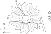
- Fig. 15 when the torque is exerted on the spool member 70 of the spool assembly, torque loading is borne by the spool tabs 71 of the spool member 70.
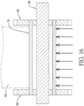
- Fig. 16 shows a state in which the spool member 70 of the spool assembly bears the loading exerted by bending.
- the stress on the spool tabs 71 connected to the spool to the ratchets 80 resulting from the radial force exerted on the spool assembly is not the same as the stress on the spool tabs 71 resulting from the linear force.
- shear stress generated by the radial force on the spool member 70 is almost evenly distributed along a periphery of the spool member 70.
- the spool member 70 is mostly a tube having a slot. The area with greater stress is located at two ends of the spool member 70 facing an axial slot 72.
- Shear stress generated by the linear force on the spool member 70 is substantially evenly distributed on the opposite side of a pulling direction of a pulling force applied by the webbing 90 to the spool member 70.
- the shear stress is located on a lower half of the spool member 70 and is changeable with a relative distance between the axial slot 72 of the spool member 70 and the webbing 90.
- the lower half of the spool member 70 is borne by two of the spool tabs 71, and the stress borne by each of the two spool tabs 71 is greater.
- the lower half of the spool member 70 is borne by three of the spool tabs 71, and the stress borne by each of the three spool tabs 71 is less.
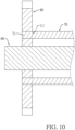
- the spool tabs 71 at two axial ends of the spool member 70 are riveted and fixed to the bodies of the two ratchets 80.
- a body of the spool member 70 and a connecting portion between the adjacent spool tabs 71 at the two axial ends of the combination of the shaft 60 and the spool member 70 cannot be supported substantively.
- a shear line L1 which acts on the spool tabs 71 of the spool member 70 and is located at an inner surface of one of the ratchets and the supporting portions, is perpendicular to a central axis of the shaft 60. A cross-sectional area of the loading is too small.
- the conventional spool assembly When the conventional spool assembly is used as a tie-down of a heavy wheelchair, during an accident, the heavy wheelchair is trusted forward and the webbing 90 is tensioned to generate the loading on the spool member 70 of the spool assembly. This could easily cause that unit-area stresses in fixing portions between the ratchets 80 and the spool member 70 are too large.
- the mechanical strength of the conventional spool assembly may be insufficient to withstand the high loading generated by the heavy wheelchair, such that the spool assembly of the tie down mechanism is prone to deformation or breakage. In order to prevent such a failure, it is necessary to improve a structure of the conventional spool assembly.
- the objective of the invention is to provide a reinforced spool assembly that can solve the problem that the mechanical strength of the conventional spool assembly of wheelchair tie down cannot sufficiently withstand the high loading created by a heavy wheelchair during an accident.
- the reinforced spool assembly has a shaft, a spool member, and two ratchets.
- the spool member is coaxially mounted around the shaft.
- a spacing is formed between an inner wall of the spool member and an outer wall of the shaft.
- Each one of the two ratchets has a body mounted on and around the outer surface of the spool member and having an inner surface and multiple teeth formed around a periphery of the body. The two inner surfaces of the two bodies face each other.
- the body has a reinforced supporting structure.
- the reinforced supporting structure is located between the outer wall of the shaft and the inner wall of the spool member.
- the reinforced supporting structure is offset from the inner surface of the body.
- An imaginary extension plane of the inner surface of the body is perpendicular to a central axis of the shaft and passes through the reinforced supporting structure.
- a first embodiment and a second embodiment of a reinforced spool assembly 1 in accordance with the present invention comprises a shaft 10, a spool member 20, and two ratchets 30.
- the shaft 10 is a circular rod with a predetermined length.
- the shaft 10 has a central axis 100 extending along an axial direction of the shaft 10.
- the spool member 20 is a circular tube with a predetermined length.
- the spool member 20 is coaxially mounted around the shaft 10.
- An inner diameter of the spool member 20 is larger than an outer diameter of the shaft 10.
- a spacing is formed between an inner wall of the spool member 20 and an outer wall of the shaft 10. The spacing is set according to product requirements for the reinforced spool assembly 1.
- the spool member 20 has multiple spool tabs 21 respectively formed on two axial ends of the spool member 20 and located around the shaft 10 at spaced intervals.
- the spool member 20 is a circular tube, which is formed by bending a metal plate, having a slot.
- the slot of the circular tube extends axially.
- a distance between two adjacent spool tabs 21 adjacent the slot is relatively wider, and a distance between the other two adjacent spool tabs 21 is relatively narrower.
- a rough, non-slip surface 22 is formed on an outer surface of the spool member 20 for ensuring connection stability between the spool member 20 and a webbing 5.
- the webbing 5 can remain flat and evenly apply a loading to the spool member 20.
- the two ratchets 30 are respectively and fixedly mounted on two axial ends of a combination of the shaft 10 and the spool member 20 with the two axial ends of the shaft (10) protruding through the bodies (31) of the two ratchets (30) respectively.
- Each one of the two ratchets 30 has a body 31 having an inner surface 31a mounted on and around an outer surface of the spool member 20 and multiple teeth 32 formed around a periphery of the body 31.
- the body 31 has an inner surface 31a and an outer surface 31b opposite to the inner surface 31a.
- the inner surface 31a is perpendicular to a central axis 100 of the shaft 10.
- the two inner surfaces 31a of the two bodies 31 face each other.
- an imaginary extension plane 310 is perpendicular to the central axis 100 of the shaft 10.
- the body 31 has a reinforced supporting structure 33A, 33B.
- the reinforced supporting structure 33A, 33B is located between the outer wall of the shaft 10 and the inner wall of the spool member 20.
- the reinforced supporting structure 33A, 33B is offset from the inner surface 31a of the body 31.
- the imaginary extension plane 310 passes through the reinforced supporting structure 33A, 33B.
- the reinforced supporting structure 33A, 33B is offset from the inner surface 31a of the body 31.
- the imaginary extension plane 310 which extends along the inner surface 31a of the body 31 and is perpendicular to the central axis 100 of the shaft 10, passes through the reinforced supporting structure 33A, 33B.
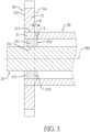
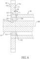
- Shear line L which acts on the spool tabs 21 of the spool member 20, is located at the inner surface 31a of the body 31, and extends to an inner surface of the reinforced supporting structure 33A, 33B, is offset and inclined for increasing a cross-sectional area. Load acting on the spool tabs 21 is effectively distributed on the larger cross-section area.
- the reinforced supporting 33A, 33B of the reinforced spool assembly 1 can be utilized in many feasible embodiments. For ease and conciseness in description, technical features of the reinforced spool assembly 1 are elaborated in conjunction with the drawings of the preferred embodiments, but not limited thereto.
- the body 31 has a center hole 311 located at a center of the body 31, a supporting area 312 located around the center hole 311, and multiple fixing holes 313 disposed around the supporting area 312. An edge of each one of the fixing holes 313 is adjacent to an outer periphery of the supporting area 312.
- Two axial ends of the shaft 10 are respectively and fixedly inserted into the two center holes 311 of the two ratchets 30.
- the spool tabs 21 respectively located on the two axial ends of the spool member 20 are respectively and fixedly inserted into the fixing holes 313 of the two ratchets 30.
- the reinforced supporting structure 33 A has a supporting ring 331 mounted around the shaft 10 and located in the supporting area 312, which is between the shaft 10 and the spool tabs 21 of the spool member 20.
- the supporting ring 331 is offset from the inner surface 31a of the body 31.
- the center hole 311 is located on the supporting ring 331 and is offset from a side, which faces a middle of the shaft 10, of one of the fixing holes 313.
- the supporting ring 331 abuts against the shaft 10 and the spool tabs 21 of the spool member 20.
- the reinforced supporting structure 33B has multiple supporting blocks 332 surrounding the supporting area 312.
- Each one of the supporting blocks 332 has a block surface.
- the block surface is a side surface of the supporting block 332 and faces the middle of the shaft 10.
- the supporting blocks 332 and the spool tabs 21 are equal in amount, and the supporting blocks 332 respectively correspond to the spool tabs 21 in position.
- Each one of the supporting blocks 332 is offset from the inner surface 31a of the body 31, is located in the supporting area 312, and is located between the shaft 10 and the corresponding spool tab 21.
- each one of the supporting blocks 332 abuts against the shaft 10 and the corresponding spool tab 21 of the spool member 20.
- the amounts of the supporting blocks 332 and the spool tabs 21 can also be different in other embodiments, and the supporting blocks 332 can be not positioned corresponding to the spool tabs 21. Increasing the amount the supporting blocks 332 can enhance the support.
- the reinforced spool assembly 1 is not only applicable to a retractor of a seat belt system in a vehicle for protecting an occupant.
- the ratchets 30 of the reinforced spool assembly 1 are locked by a brake assembly of the retractor.
- the webbing 5 fastened on the wheelchair is in a tensioned state.
- the spool member 20 connected to the webbing 5 has the reinforced supporting structures 33A, 33B disposed on the two bodies 31 of the two ratchets 30 for effectively distributing the loading exerted on the spool tabs 21on the larger cross-section area. Stress per unit area between the ratchets 30 and the spool member 20 is reduced.
- the mechanical strength of the reinforced spool assembly 1 is increased in bearing higher loadings, sufficiently satisfying safety requirements for the retractor of the seat belt system.
- the reinforced spool assembly 1 is also used in a tie-down 3 fixing a heavy wheelchair 2 carried by vehicles, such as rehabilitation buses and public transportation vehicles allowed to carry wheelchairs.
- the tie-down 3 having the reinforced spool assembly 1 is mounted on a floor of the vehicle by a fixed fixing mechanism or a fixing mechanism 4.
- the webbing 5 connected to the reinforced spool assembly 1 is pulled out of a shell of the tie-down 3.
- a clasp mounted on a distal end of the webbing 5 is hooked to a frame of the heavy wheelchair 2.
- Four tie-downs 3 are disposed at two sides of a front end and a rear end of the heavy wheelchair 2 for fixing the heavy wheelchair 2 on the floor of the vehicle.
- the four tie-downs 3 disposed around the heavy wheelchair 2 provide a balanced and stable traction force to ensure that the heavy wheelchair 2 remains fixed to the floor of the vehicle.
- each one of the reinforced supporting structures 33A, 33B is offset from the inner surface 3 la of a corresponding one of the two ratchets 30.
- the imaginary extension plane 310 is perpendicular to the central axis 100 of the shaft 10.
- Shear line L which acts on the spool tabs 21 of the spool member 20, is located at the inner surface 31a of the body 31, and extends to the inner surface of the reinforced supporting structure 33A, 33B, is offset and inclined for increasing the cross-section area.
- the load acting on the spool tabs 21 is effectively distributed on the larger cross-section area.
- the stress per unit area in the connecting part between each one of the ratchets 30 and the spool member 20 is reduced.
- Mechanical strength of the reinforced spool assembly 1 is increased in bearing high loadings exerted on the reinforced tie-down 3.
Landscapes
- Engineering & Computer Science (AREA)
- Mechanical Engineering (AREA)
- Health & Medical Sciences (AREA)
- Public Health (AREA)
- Life Sciences & Earth Sciences (AREA)
- Animal Behavior & Ethology (AREA)
- General Health & Medical Sciences (AREA)
- Veterinary Medicine (AREA)
- Automotive Seat Belt Assembly (AREA)
- Storage Of Web-Like Or Filamentary Materials (AREA)
- Coils Of Transformers For General Uses (AREA)
Claims (6)
- Verstärkte-Aufwickelspule-Vorrichtung (1), dadurch gekennzeichnet, dass die Verstärkte-Aufwickelspule-Vorrichtung (1) aufweist:eine Welle (10);ein Aufwickelspule-Element (20), welches koaxial um die Welle (10) herum montiert ist, wobei ein Abstand zwischen einer Innenwand des Aufwickelspule-Elements (20) und einer Außenwand der Welle (10) gebildet ist;zwei Sperrklinken (30), wobei jede von den zwei Sperrklinken (30) hat:einen Körper (31), welcher an und um eine Außenfläche des Aufwickelspule-Elements (20) herum montiert ist und eine Innenfläche (31a) hat; undmehrere Zähne (32), welche um einen Randbereich des Körpers (31) herum gebildet sind;wobei die zwei Innenflächen (31a) der zwei Körper (31) einander zugewandt sind, und zwei axiale Enden der Welle (10) in jeweils zugeordneter Weise durch die Körper (31) der zwei Sperrklinken (30) hindurchragen; undwobei der Körper (31) eine Verstärkte-Lagerung-Struktur (33A, 33B) hat, sich die Verstärkte-Lagerung-Struktur (33A, 33B) zwischen der Außenwand der Welle (10) und der Innenwand des Aufwickelspule-Elements (20) befindet, die Verstärkte-Lagerung-Struktur (33A, 33B) von der Innenfläche (31a) des Körpers (31) aus versetzt ist, eine imaginäre Verlängerungsebene (310) der Innenfläche (31a) des Körpers (31) senkrecht zu einer Mittelachse (100) der Welle (10) ist und durch die Verstärkte-Lagerung-Struktur (33A, 33B) hindurchgeht.
- Verstärkte-Aufwickelspule-Vorrichtung (1) gemäß Anspruch 1, wobei in jedem von den zwei Körpern (31) der zwei Sperrklinken (30) die Verstärkte-Lagerung-Struktur (33A) einen Lagerring (331) hat, welcher um die Welle (10) herum montiert ist, wobei eine Seitenfläche des Lagerrings (331), welche einer Mitte des Aufwickelspule-Elements (20) zugewandt ist, von der Innenfläche (31a) des Körpers (31) aus versetzt ist.
- Verstärkte-Aufwickelspule-Vorrichtung (1) gemäß Anspruch 2, wobei das Aufwickelspule-Element (20) mehrere Aufwickelspule-Vorsprünge (21) hat, welche in jeweils zugeordneter Weise an zwei axialen Enden des Aufwickelspule-Elements (20) gebildet sind und in beabstandeten Abständen um die Welle (10) herum angeordnet sind;wobei bei jeder von den zwei Sperrklinken (30) der Körper (31) ein Mittelloch (311), welches sich an einer Mitte des Körpers (31) befindet, einen Lagerbereich (312), welcher sich um das Mittelloch (311) herum befindet, und mehrere Befestigungslöcher (313) hat, welche um den Lagerbereich (312) herum angeordnet sind, wobei ein Rand von jedem von den Befestigungslöchern (313) zu einem Außenrandbereich des Lagerbereichs (312) benachbart ist;wobei die zwei axialen Enden der Welle (10) in jeweils zugeordneter und fixierter Weise in die zwei Mittellöcher (311) der zwei Sperrklinken (30) hinein eingesetzt sind, wobei die Aufwickelspule-Vorsprünge (21), welche an den zwei axialen Enden des Aufwickelspule-Elements (20) gebildet sind, in jeweils zugeordneter und fixierter Weise in die Befestigungslöcher (313) der zwei Sperrklinken (30) hinein eingesetzt sind; wobei sich der Lagerring (331) der Verstärkte-Lagerung-Struktur (33A, 33B) in dem Lagerbereich (312) befindet und an der Welle (10) und den Aufwickelspule-Vorsprüngen (21) des Aufwickelspule-Elements (20) anliegt.
- Verstärkte-Aufwickelspule-Vorrichtung (1) gemäß Anspruch 1, wobei bei jedem von den zwei Körpern (31) der zwei Sperrklinken (30) die Verstärkte-Lagerung-Struktur (33B) mehrere Lagerblöcke (332) hat, welche die Welle (10) umgeben, wobei jeder von den Lagerblöcken (332) eine Blockfläche hat; wobei die Blockfläche eine Seitenfläche des Lagerblocks (332) ist, welche einer Mitte der Welle (10) zugewandt ist, und von der Innenfläche (31a) des Körpers (31) aus versetzt ist, und jeder von den Lagerblöcken (332) an der Welle (10) und dem Aufwickelspule-Element (20) anliegt.
- Verstärkte-Aufwickelspule-Vorrichtung (1) gemäß Anspruch 4, wobei das Aufwickelspule-Element (20) mehrere Aufwickelspule-Vorsprünge (21) hat, welche in jeweils zugeordneter Weise an zwei axialen Enden des Aufwickelspule-Elements (20) gebildet sind und sich in beabstandeten Abständen um die Welle (10) herum befinden;wobei der Körper (31) ein Mittelloch (311), welches sich an einer Mitte des Körpers (31) befindet, einen Lagerbereich (312), welcher sich um das Mittelloch (311) herum befindet, und mehrere Befestigungslöcher (313) hat, welche um den Lagerbereich (312) herum angeordnet sind, wobei ein Rand von jedem von den Befestigungslöchern (313) zu einem äußeren Randbereich des Lagerbereichs (312) benachbart ist;wobei die zwei axialen Enden der Welle (10) in jeweils zugeordneter und fixierter Weise in die zwei Mittellöcher (311) der zwei Sperrklinken (30) hinein eingesetzt sind, wobei die Aufwickelspule-Vorsprünge (21), welche an den zwei axialen Enden des Aufwickelspule-Elements (20) gebildet sind, in jeweils zugeordneter und fixierter Weise in die Befestigungslöcher (313) der zwei Sperrklinken (30) hinein eingesetzt sind; wobei sich jeder von den Lagerblöcken (332) der Verstärkte-Lagerung-Struktur (33B) in dem Lagerbereich (312) befindet; wobei die Lagerblöcke (332) und die Aufwickelspule-Vorsprünge (21) in der gleichen Anzahl vorliegen, und die Lagerblöcke (332) in jeweils zugeordneter Weise mit den Aufwickelspule-Vorsprüngen (21) korrespondieren; wobei jeder von den Lagerblöcken (332) zwischen dem korrespondierenden Aufwickelspule-Vorsprung und der Welle (10) anliegt.
- Verstärkte-Aufwickelspule-Vorrichtung (1) gemäß Anspruch 1, wobei das Aufwickelspule-Element (20) eine rutschfeste Fläche (22) hat, welche an der Außenfläche des Aufwickelspule-Elements (20) gebildet ist.
Applications Claiming Priority (1)
| Application Number | Priority Date | Filing Date | Title |
|---|---|---|---|
| US202163232709P | 2021-08-13 | 2021-08-13 |
Publications (3)
| Publication Number | Publication Date |
|---|---|
| EP4134054A1 EP4134054A1 (de) | 2023-02-15 |
| EP4134054B1 true EP4134054B1 (de) | 2025-06-25 |
| EP4134054C0 EP4134054C0 (de) | 2025-06-25 |
Family
ID=82786792
Family Applications (1)
| Application Number | Title | Priority Date | Filing Date |
|---|---|---|---|
| EP22188211.1A Active EP4134054B1 (de) | 2021-08-13 | 2022-08-02 | Verstärkte spulenbaugruppe |
Country Status (6)
| Country | Link |
|---|---|
| US (1) | US20230053255A1 (de) |
| EP (1) | EP4134054B1 (de) |
| JP (1) | JP7412027B2 (de) |
| CN (1) | CN115703426B (de) |
| ES (1) | ES3040804T3 (de) |
| TW (1) | TWI837736B (de) |
Family Cites Families (31)
| Publication number | Priority date | Publication date | Assignee | Title |
|---|---|---|---|---|
| JPS4956623U (de) * | 1972-08-25 | 1974-05-18 | ||
| JPS6135063U (ja) * | 1984-08-06 | 1986-03-04 | 株式会社東海理化電機製作所 | ウエビング巻取装置用巻取軸 |
| GB2210251B (en) * | 1987-10-02 | 1991-10-30 | Autoliv Dev | Improvements in or relating to a seat belt retractor |
| JPH01102053U (de) * | 1987-12-28 | 1989-07-10 | ||
| JPH01102052U (de) * | 1987-12-28 | 1989-07-10 | ||
| DE20111409U1 (de) * | 2001-07-10 | 2001-11-15 | TRW Occupant Restraint Systems GmbH & Co. KG, 73553 Alfdorf | Gurtspule |
| US5533756A (en) * | 1994-08-04 | 1996-07-09 | Alliedsignal Inc. | Seat belt retractor with energy absorbing lock wheels |
| DE29513942U1 (de) * | 1995-08-30 | 1997-01-09 | Trw Repa Gmbh, 73553 Alfdorf | Kraftbegrenzer an einem Gurtaufroller für Sicherheitsgurte |
| DE29613044U1 (de) * | 1995-11-09 | 1996-11-07 | Trw Occupant Restraint Systems Gmbh, 73551 Alfdorf | Gurtaufroller für einen Fahrzeug-Sicherheitsgurt |
| DE29605115U1 (de) * | 1996-03-19 | 1996-07-18 | Trw Occupant Restraint Systems Gmbh, 73551 Alfdorf | Gurtaufroller |
| US5785269A (en) * | 1997-02-06 | 1998-07-28 | Alliedsignal Inc. | Dual level retractor for oblique or offset impacts |
| US5799893A (en) * | 1997-02-19 | 1998-09-01 | Alliedsignal Inc. | Multi-level load limiting torsion bar retractor |
| US6299091B1 (en) * | 1999-01-27 | 2001-10-09 | Breed Automotive Technology, Inc. | Seat belt retractor spool and torsion bar |
| GB2354208B (en) * | 1999-09-17 | 2003-11-26 | Breed Automotive Tech | Retractor |
| GB2354205B (en) * | 1999-09-17 | 2001-11-28 | Breed Automotive Tech | Retractor |
| JP4514271B2 (ja) * | 2000-02-23 | 2010-07-28 | タカタ株式会社 | シートベルトリトラクタ |
| GB2376665B (en) * | 2001-06-19 | 2003-05-28 | Breed Automotive Tech | Retractor spool |
| US6969022B2 (en) * | 2003-10-14 | 2005-11-29 | Key Safety Systems, Inc. | Seat belt retractor |
| JP2006137290A (ja) * | 2004-11-11 | 2006-06-01 | Tokai Rika Co Ltd | ウエビング巻取装置 |
| JP2006256514A (ja) * | 2005-03-17 | 2006-09-28 | Tokai Rika Co Ltd | ウエビング巻取装置 |
| JP4908927B2 (ja) * | 2005-08-22 | 2012-04-04 | 株式会社東海理化電機製作所 | ウエビング巻取装置 |
| JP5086210B2 (ja) * | 2008-09-03 | 2012-11-28 | 株式会社東海理化電機製作所 | ウエビング巻取装置 |
| JP5384438B2 (ja) * | 2010-06-18 | 2014-01-08 | 株式会社東海理化電機製作所 | ウエビング巻取装置 |
| JP2012180040A (ja) * | 2011-03-02 | 2012-09-20 | Ashimori Industry Co Ltd | シートベルト用リトラクタ |
| DE102012016614A1 (de) * | 2012-08-23 | 2014-02-27 | Trw Automotive Gmbh | Gurtspule |
| EP2889191B1 (de) * | 2012-08-27 | 2019-10-02 | Helia Technology Limited | Aufwickelvorrichtung für einen sicherheitsgurt, torsionsstab, spule, endkappe und sicherheitsgurtanordnung |
| CN102837664B (zh) * | 2012-08-27 | 2016-01-13 | 上海和励信息科技有限公司 | 一种用于安全带的卷收器和安全带总成 |
| JP5714624B2 (ja) * | 2013-02-22 | 2015-05-07 | 株式会社東海理化電機製作所 | ウェビング巻取装置 |
| DE102014115199A1 (de) * | 2014-10-19 | 2016-04-21 | Franz Wier | Kunststoff Gurtspulen und Gurtspulenbaugruppen |
| DE102017218564A1 (de) * | 2017-10-18 | 2019-04-18 | Robert Bosch Gmbh | Verfahren und Steuergerät zum Laden eines Personenschutzmittel-Energiespeichers zum Betreiben eines Personenschutzmittels eines Fahrzeugs |
| CN212637407U (zh) * | 2020-06-28 | 2021-03-02 | 宁波明讯实业有限公司 | 一种汽车用安全带芯轴 |
-
2022
- 2022-07-25 TW TW111127728A patent/TWI837736B/zh active
- 2022-07-28 CN CN202210896548.3A patent/CN115703426B/zh active Active
- 2022-07-29 US US17/876,720 patent/US20230053255A1/en active Pending
- 2022-08-02 EP EP22188211.1A patent/EP4134054B1/de active Active
- 2022-08-02 ES ES22188211T patent/ES3040804T3/es active Active
- 2022-08-05 JP JP2022125619A patent/JP7412027B2/ja active Active
Also Published As
| Publication number | Publication date |
|---|---|
| JP7412027B2 (ja) | 2024-01-12 |
| JP2023026363A (ja) | 2023-02-24 |
| CN115703426A (zh) | 2023-02-17 |
| TW202306812A (zh) | 2023-02-16 |
| EP4134054C0 (de) | 2025-06-25 |
| EP4134054A1 (de) | 2023-02-15 |
| TWI837736B (zh) | 2024-04-01 |
| ES3040804T3 (en) | 2025-11-05 |
| CN115703426B (zh) | 2025-10-03 |
| US20230053255A1 (en) | 2023-02-16 |
Similar Documents
| Publication | Publication Date | Title |
|---|---|---|
| US7887139B2 (en) | Vehicle seat frame | |
| EP0852191B1 (de) | Energieabsorbierende Struktur für ein Kraftfahrzeug | |
| US6568745B2 (en) | Automobile body structure | |
| US5722611A (en) | Belt retractor | |
| US7367589B2 (en) | Collapsible steering assembly with a stationary reaction surface | |
| EP4071005A1 (de) | Sitzgurtanordnung | |
| EP4134054B1 (de) | Verstärkte spulenbaugruppe | |
| US20220281358A1 (en) | Reinforced track assembly for vehicle seat | |
| JP4183384B2 (ja) | トーションバーを備えたシートベルトリトラクタ | |
| EP1274612A1 (de) | Befestigungsanordnung für sicherheitsgurtaufroller mit verstärkungsplatte | |
| EP1036717A3 (de) | Sperrstange mit Kompensierung gegen Rahmenverformung | |
| EP4082826B1 (de) | Sitzschienensystem für ein fahrzeug und fahrzeug mit einem sitzschienensystem | |
| US12194954B2 (en) | Integrated seat belt energy management loop | |
| EP3075607B1 (de) | Struktur für einen auslaufschutz | |
| JPH0411884Y2 (de) | ||
| JP6807417B2 (ja) | ラッププリテンショナの車体取付構造 | |
| JPH10119504A (ja) | フロントアクスル | |
| KR100465252B1 (ko) | 좌석 벨트 리트랙터용 잠금 바 | |
| US12404969B1 (en) | Bracket design for recreational vehicles | |
| JP2021195032A (ja) | シートベルトリトラクタ及びシートベルト装置 | |
| US20240034207A1 (en) | A seat rail system for a vehicle and a vehicle comprising a seat rail system | |
| US5033691A (en) | Webbing retractor | |
| KR20020037760A (ko) | 좌석 벨트 수축기 | |
| CN223686516U (zh) | 安全带固定装置及车辆 | |
| DE19858300C2 (de) | Radfelge für ein Kraftfahrzeug |
Legal Events
| Date | Code | Title | Description |
|---|---|---|---|
| PUAI | Public reference made under article 153(3) epc to a published international application that has entered the european phase |
Free format text: ORIGINAL CODE: 0009012 |
|
| STAA | Information on the status of an ep patent application or granted ep patent |
Free format text: STATUS: THE APPLICATION HAS BEEN PUBLISHED |
|
| AK | Designated contracting states |
Kind code of ref document: A1 Designated state(s): AL AT BE BG CH CY CZ DE DK EE ES FI FR GB GR HR HU IE IS IT LI LT LU LV MC MK MT NL NO PL PT RO RS SE SI SK SM TR |
|
| STAA | Information on the status of an ep patent application or granted ep patent |
Free format text: STATUS: REQUEST FOR EXAMINATION WAS MADE |
|
| 17P | Request for examination filed |
Effective date: 20230815 |
|
| RBV | Designated contracting states (corrected) |
Designated state(s): AL AT BE BG CH CY CZ DE DK EE ES FI FR GB GR HR HU IE IS IT LI LT LU LV MC MK MT NL NO PL PT RO RS SE SI SK SM TR |
|
| GRAP | Despatch of communication of intention to grant a patent |
Free format text: ORIGINAL CODE: EPIDOSNIGR1 |
|
| STAA | Information on the status of an ep patent application or granted ep patent |
Free format text: STATUS: GRANT OF PATENT IS INTENDED |
|
| INTG | Intention to grant announced |
Effective date: 20250121 |
|
| GRAS | Grant fee paid |
Free format text: ORIGINAL CODE: EPIDOSNIGR3 |
|
| GRAA | (expected) grant |
Free format text: ORIGINAL CODE: 0009210 |
|
| STAA | Information on the status of an ep patent application or granted ep patent |
Free format text: STATUS: THE PATENT HAS BEEN GRANTED |
|
| AK | Designated contracting states |
Kind code of ref document: B1 Designated state(s): AL AT BE BG CH CY CZ DE DK EE ES FI FR GB GR HR HU IE IS IT LI LT LU LV MC MK MT NL NO PL PT RO RS SE SI SK SM TR |
|
| REG | Reference to a national code |
Ref country code: GB Ref legal event code: FG4D |
|
| REG | Reference to a national code |
Ref country code: CH Ref legal event code: EP |
|
| REG | Reference to a national code |
Ref country code: CH Ref legal event code: EP |
|
| REG | Reference to a national code |
Ref country code: IE Ref legal event code: FG4D |
|
| U01 | Request for unitary effect filed |
Effective date: 20250627 |
|
| U07 | Unitary effect registered |
Designated state(s): AT BE BG DE DK EE FI FR IT LT LU LV MT NL PT RO SE SI Effective date: 20250703 |
|
| U20 | Renewal fee for the european patent with unitary effect paid |
Year of fee payment: 4 Effective date: 20250811 |
|
| PGFP | Annual fee paid to national office [announced via postgrant information from national office to epo] |
Ref country code: ES Payment date: 20250910 Year of fee payment: 4 |
|
| PG25 | Lapsed in a contracting state [announced via postgrant information from national office to epo] |
Ref country code: NO Free format text: LAPSE BECAUSE OF FAILURE TO SUBMIT A TRANSLATION OF THE DESCRIPTION OR TO PAY THE FEE WITHIN THE PRESCRIBED TIME-LIMIT Effective date: 20250925 Ref country code: GR Free format text: LAPSE BECAUSE OF FAILURE TO SUBMIT A TRANSLATION OF THE DESCRIPTION OR TO PAY THE FEE WITHIN THE PRESCRIBED TIME-LIMIT Effective date: 20250926 |
|
| PG25 | Lapsed in a contracting state [announced via postgrant information from national office to epo] |
Ref country code: HR Free format text: LAPSE BECAUSE OF FAILURE TO SUBMIT A TRANSLATION OF THE DESCRIPTION OR TO PAY THE FEE WITHIN THE PRESCRIBED TIME-LIMIT Effective date: 20250625 |
|
| PG25 | Lapsed in a contracting state [announced via postgrant information from national office to epo] |
Ref country code: RS Free format text: LAPSE BECAUSE OF FAILURE TO SUBMIT A TRANSLATION OF THE DESCRIPTION OR TO PAY THE FEE WITHIN THE PRESCRIBED TIME-LIMIT Effective date: 20250925 |
|
| REG | Reference to a national code |
Ref country code: ES Ref legal event code: FG2A Ref document number: 3040804 Country of ref document: ES Kind code of ref document: T3 Effective date: 20251105 |
|
| PG25 | Lapsed in a contracting state [announced via postgrant information from national office to epo] |
Ref country code: IS Free format text: LAPSE BECAUSE OF FAILURE TO SUBMIT A TRANSLATION OF THE DESCRIPTION OR TO PAY THE FEE WITHIN THE PRESCRIBED TIME-LIMIT Effective date: 20251025 |
|
| PG25 | Lapsed in a contracting state [announced via postgrant information from national office to epo] |
Ref country code: SM Free format text: LAPSE BECAUSE OF FAILURE TO SUBMIT A TRANSLATION OF THE DESCRIPTION OR TO PAY THE FEE WITHIN THE PRESCRIBED TIME-LIMIT Effective date: 20250625 |
|
| PG25 | Lapsed in a contracting state [announced via postgrant information from national office to epo] |
Ref country code: CZ Free format text: LAPSE BECAUSE OF FAILURE TO SUBMIT A TRANSLATION OF THE DESCRIPTION OR TO PAY THE FEE WITHIN THE PRESCRIBED TIME-LIMIT Effective date: 20250625 |
|
| PG25 | Lapsed in a contracting state [announced via postgrant information from national office to epo] |
Ref country code: PL Free format text: LAPSE BECAUSE OF FAILURE TO SUBMIT A TRANSLATION OF THE DESCRIPTION OR TO PAY THE FEE WITHIN THE PRESCRIBED TIME-LIMIT Effective date: 20250625 |
|
| PG25 | Lapsed in a contracting state [announced via postgrant information from national office to epo] |
Ref country code: SK Free format text: LAPSE BECAUSE OF FAILURE TO SUBMIT A TRANSLATION OF THE DESCRIPTION OR TO PAY THE FEE WITHIN THE PRESCRIBED TIME-LIMIT Effective date: 20250625 |
|
| REG | Reference to a national code |
Ref country code: CH Ref legal event code: H13 Free format text: ST27 STATUS EVENT CODE: U-0-0-H10-H13 (AS PROVIDED BY THE NATIONAL OFFICE) Effective date: 20260324 |
|
| PG25 | Lapsed in a contracting state [announced via postgrant information from national office to epo] |
Ref country code: MC Free format text: LAPSE BECAUSE OF FAILURE TO SUBMIT A TRANSLATION OF THE DESCRIPTION OR TO PAY THE FEE WITHIN THE PRESCRIBED TIME-LIMIT Effective date: 20250625 |
|
| PG25 | Lapsed in a contracting state [announced via postgrant information from national office to epo] |
Ref country code: CH Free format text: LAPSE BECAUSE OF NON-PAYMENT OF DUE FEES Effective date: 20250831 |
|
| PLBE | No opposition filed within time limit |
Free format text: ORIGINAL CODE: 0009261 |
|
| STAA | Information on the status of an ep patent application or granted ep patent |
Free format text: STATUS: NO OPPOSITION FILED WITHIN TIME LIMIT |