EP2889191B1 - Aufwickelvorrichtung für einen sicherheitsgurt, torsionsstab, spule, endkappe und sicherheitsgurtanordnung - Google Patents
Aufwickelvorrichtung für einen sicherheitsgurt, torsionsstab, spule, endkappe und sicherheitsgurtanordnung Download PDFInfo
- Publication number
- EP2889191B1 EP2889191B1 EP13833997.3A EP13833997A EP2889191B1 EP 2889191 B1 EP2889191 B1 EP 2889191B1 EP 13833997 A EP13833997 A EP 13833997A EP 2889191 B1 EP2889191 B1 EP 2889191B1
- Authority
- EP
- European Patent Office
- Prior art keywords
- torsion bar
- spindle
- external teeth
- bar
- force
- Prior art date
- Legal status (The legal status is an assumption and is not a legal conclusion. Google has not performed a legal analysis and makes no representation as to the accuracy of the status listed.)
- Active
Links
- 230000002093 peripheral effect Effects 0.000 claims description 14
- 230000004323 axial length Effects 0.000 claims description 11
- 239000004744 fabric Substances 0.000 description 59
- 230000000670 limiting effect Effects 0.000 description 41
- 238000000034 method Methods 0.000 description 19
- 230000008569 process Effects 0.000 description 15
- 230000000694 effects Effects 0.000 description 11
- 239000000463 material Substances 0.000 description 11
- 238000004519 manufacturing process Methods 0.000 description 9
- 230000036961 partial effect Effects 0.000 description 8
- 230000008878 coupling Effects 0.000 description 7
- 238000010168 coupling process Methods 0.000 description 7
- 238000005859 coupling reaction Methods 0.000 description 7
- 238000010586 diagram Methods 0.000 description 6
- 230000008859 change Effects 0.000 description 5
- 239000002184 metal Substances 0.000 description 4
- 208000027418 Wounds and injury Diseases 0.000 description 3
- 230000009286 beneficial effect Effects 0.000 description 3
- 230000008901 benefit Effects 0.000 description 3
- 238000004804 winding Methods 0.000 description 3
- 238000004026 adhesive bonding Methods 0.000 description 2
- 238000005452 bending Methods 0.000 description 2
- 230000006378 damage Effects 0.000 description 2
- 208000014674 injury Diseases 0.000 description 2
- 238000009434 installation Methods 0.000 description 2
- 230000001681 protective effect Effects 0.000 description 2
- 230000002829 reductive effect Effects 0.000 description 2
- 239000007858 starting material Substances 0.000 description 2
- 230000009471 action Effects 0.000 description 1
- 230000004520 agglutination Effects 0.000 description 1
- 238000006243 chemical reaction Methods 0.000 description 1
- 230000007423 decrease Effects 0.000 description 1
- 230000003247 decreasing effect Effects 0.000 description 1
- 230000018109 developmental process Effects 0.000 description 1
- 238000009826 distribution Methods 0.000 description 1
- 210000003608 fece Anatomy 0.000 description 1
- 230000007246 mechanism Effects 0.000 description 1
- 230000000717 retained effect Effects 0.000 description 1
Images


Classifications
-
- B—PERFORMING OPERATIONS; TRANSPORTING
- B60—VEHICLES IN GENERAL
- B60R—VEHICLES, VEHICLE FITTINGS, OR VEHICLE PARTS, NOT OTHERWISE PROVIDED FOR
- B60R22/00—Safety belts or body harnesses in vehicles
- B60R22/34—Belt retractors, e.g. reels
- B60R22/341—Belt retractors, e.g. reels comprising energy-absorbing means
- B60R22/3413—Belt retractors, e.g. reels comprising energy-absorbing means operating between belt reel and retractor frame
-
- B—PERFORMING OPERATIONS; TRANSPORTING
- B60—VEHICLES IN GENERAL
- B60R—VEHICLES, VEHICLE FITTINGS, OR VEHICLE PARTS, NOT OTHERWISE PROVIDED FOR
- B60R22/00—Safety belts or body harnesses in vehicles
- B60R22/34—Belt retractors, e.g. reels
-
- B—PERFORMING OPERATIONS; TRANSPORTING
- B60—VEHICLES IN GENERAL
- B60R—VEHICLES, VEHICLE FITTINGS, OR VEHICLE PARTS, NOT OTHERWISE PROVIDED FOR
- B60R22/00—Safety belts or body harnesses in vehicles
- B60R22/34—Belt retractors, e.g. reels
- B60R2022/3402—Retractor casings; Mounting thereof
-
- B—PERFORMING OPERATIONS; TRANSPORTING
- B60—VEHICLES IN GENERAL
- B60R—VEHICLES, VEHICLE FITTINGS, OR VEHICLE PARTS, NOT OTHERWISE PROVIDED FOR
- B60R22/00—Safety belts or body harnesses in vehicles
- B60R22/34—Belt retractors, e.g. reels
- B60R2022/3427—Seat belt connection on reels
Definitions
- the present invention relates to a technical field of a safety belt, and more particularly to a winder used for a safety belt.
- the present invention relates to a safety belt assembly which uses the winder, and a torsion bar a reel, and end covers used for the above winder.
- a safety belt is a passive safety component applied to vehicles which is very important. When a vehicle crash happens, a safety belt shall make the person who uses the safety belt get rid of being hurt, or relieve the hurt on the user.
- a safety belt shall make the person who uses the safety belt get rid of being hurt secondly, or relieve the secondary hurt to the user.
- the standard three-points safety belt initially designed to be applied to car seat merely comprises a locking structure and a fabric belt used for fixing the user.
- the locking structure locks and the fabric belt stops being pulled out, and thus the user is bound around the car seat.
- the time of changing is so short because of the rapid changes of the speed of the car at the time of the crash that the force from the fabric belt applied on the user is huge, such as 810Kn, which may break off the ribs of the user, or bring worse hurt to the user.
- the present invention proposes the force-limiting safety belt which is a development of the standard safety belt, and the present invention shall limit the force which the fabric belt applies on a human body by certain force-limiting structures when a vehicle crash occurs at the time of the crash. Thus, the user will not be hurt by the fabric belt and is protected farthest.
- the European Patent whose document no. is EP1607288B1 discloses a safety apparatus used for force-limiting safety belt.
- the second embodiment of the said European patent discloses a safety apparatus which comprises a U-shaped frame, a reel and a torsion bar. The two corresponding positions on the two side walls of the said U-shaped frame are provided with two circular openings which has internal teeth thereon.
- the reel comprises a spindle used for binding the fabric belt and two detachable end covers provided on two ends of the spindle.
- the said end covers have external teeth provided thereon which are to set be engaged with the internal teeth on the frame.
- the said reel can be provided in the frame rotatbly and floatly, with two end covers respectively being provided in the said U-shaped frame. Under normal circumstance, the external teeth on the two end covers are not engaged with the internal teeth on the two circular openings, so that the reel is able to rotate in the said circular opening to bind or release the fabric belt.
- the sensing device triggers the action structure including the gas generator, so that the external teeth on the end covers of the reel are engaged with the internal teeth on the U-shaped frame and the reel is locked in the frame, leading to the fabric belt bound around the spindle stopping being released out, and thus the user is fixed in the seat.
- the forward moving force produced by inertance becomes larger and larger, which always tries to drive the spindle of the reel to rotate, but the spindle is fixed in the U-shaped by means of the spindle being engaged with the torsion bar and the end covers being engaged with the torsion bar so that the spindle is unable to rotate.
- the spindle When the traction of the fabric belt is large enough to make the torsion bar distort and rotate, the spindle will rotate in certain angle, so that the fabric belt is released by certain length, and accordingly, the user is able to move forwardly in certain distance, and thereby the traction from the fabric belt applied to the user is relieved and the purpose of limiting the force from the fabric applied to the user is reached, and the force limiting effect is obtained.
- the force limiting safety apparatus disclosed in the above European patent has some problems which main lie in that the apparatus locks by means of the circumferential external teeth on the end covers of the winder being engaged with the circumferential internal teeth on the U-shaped frame, but the locking position is not set at a fixed place which may occur at several positions, which brings uncertain of the locking and difficulty of controlling the locking.
- the above invention should be improved.
- the present invention provides a winder used for a safety belt, which can overcome the problem of uncertain locking position of the winder in the background invention, and improve the sustainability of the safety belt which has used the winder.
- the present invention provides a safety belt assembly which has used the safety belt winder, and the safety belt assembly has all beneficial effects brought by the winder.
- the present invention further provides a torsion bar used for a safety belt winder.
- the present invention further provides end covers used for a safety belt winder.
- the present invention provides a winder used for a safety belt, comprising a winder frame, a reel and a torsion bar; wherein, the winder frame comprises of two opposite sidewalls, circular openings with internal toothed segments being provided on a corresponding position in the two sidewalls, the toothed segments being provided at a position where a fabric belt is extracted outward.
- the reel comprises a spindle, two detachable end covers and a torsion bar, the spindle having a through hole along its central axis, the spindle also being used for winding the fabric belt, the two end covers being attached on the ends of the spindle; the external teeth which engage with the teeth in the frame are provided along the periphery of the end covers; the said torsion bar which is in form of rod is provided in the said through hole of the spindle along the axis of the reel, two ends of which are able to extend to the two end covers of the spindle, middle portion of which in axile direction is provided with external teeth, and the internal teeth which are engaged with the external teeth are provided in the through hole of the said spindle; by means of the said internal teeth being engaged with the external teeth, the torsion bar is connected with the spindle; the torsion bar is also connected with the two detachable end covers by means of setting of the gears at the crossing position of the torsion bar and the said two end covers,
- the reel In a fully assembled state, the reel can be rotate and float within the winder frame, the two end covers being inside the openings of the two sidewalls of the winder frame; in a locked state, the external teeth of the two end covers of the winder engage with the teeth of the frame.
- the connecting structure of the said torsion bar and the two end covers of the two ends is as below: the center of the end face which faces the spindle is provided with a shrinkage hole which has internal teeth; end of the torsion bar is inserted into the shrinkage hole and provided with the external teeth which are designed to be engaged with the internal teeth in the shrinkage hole on the inner end face of the end cover.
- the position of the middle segment external teeth at the middle portion of the torsion bar which corresponds to the position of the fixing through hole used for traversing and fixing the fabric belt of the safety belt is provided with avoiding missing tooth;
- the position at the circumferential external teeth of the end of the torsion bar which corresponds to the said position of the avoiding missing tooth is provided with error preventing tooth;
- the position of the internal teeth of the shrinkage hole on the inner end face is provided with a toothed missing structure which matches with the said error preventing.
- the torsion bar is engaged with one end cover by connecting the external tooth profile of the bar with an internal tooth profile on the end cover, this end cover being called the first end cover; the side of the other end cover which faces the spindle has a circular boss provided thereon, the circular boss having internal threads, a separate ring having an internal tooth profile and external threads, connects the torsion bar to the end cover, the torsion bars external teeth profile fitting inside the ring and the outside threads of the ring screwing into the threaded boss on the end cover, this end cover being called the second end cover.
- the profile of the external teeth at the middle portion of the torsion bar inclines to the end which has an error preventing provided.
- the length in axile direction of the torsion bar is not longer than the axile length of the said end cover.
- the torsion bar is divided into two segments in axial direction, two ends of which are provided with external teeth, and the profile of the teeth of the two ends of the two segments at the adjoining portion align with each other; the circumferential external teeth on the adjoining portion of the two segments makes the middle segment external teeth of the torsion bar, which having the external teeth provided thereon, the external teeth being engaged with the corresponding internal teeth tooth profiles of external teeth on adjoining portion of the two bar segments aligning with each other, making the central external toothed segment.
- the diameters and materials of the two segments of the torsion bar are different.
- the axial effective length of two bar segments at two sides of the peripheral external teeth in middle portion of the torsion bar are different; wherein, the effective length refers to the axial length of the torsion bar or bar segments excluding the axial length of the external teeth on the two ends.
- At least two shear pins are provided on both sides of the spindle; the shear pins are fixed on the end face of the spindle, and inserted into the corresponding pin orifice on the end cover; or the shear pin is fixed on the end cover, and inserted into the corresponding pin orifice on the end face of the spindle.
- the positions of the two shear pins of the spindle are different, preventing the left and right end covers from being incorrectly assembled, and guaranteeing that the external teeth of the two end covers have staggered and fixed angle after being installed.
- adjoining end faces of the spindle and the end cover are provided with spigots which couple with each other.
- the position of the spigot is provided with wear ring.
- Outer board of the inner end face of each end cover is provided with annular boss, and the position of the two end feces of the said spindle which corresponds to the said circular boss is provided with avoiding spigot.
- the present invention provides a safety belt assembly, which has used a winder made by means of any above technical art.
- the present invention provides a torsion bar used for a safety belt assembly, wherein, the two ends and middle portion of the torsion bar which is in form of rod are provided with circumferential external teeth, and the external teeth on the two ends of the torsion bar are engaged with the internal teeth in the shrinkage hole on the end faces of the end covers of the winder; the said torsion bar is divided into two segments in axial direction which are connected to each other by adjoining ends, wherein, the external teeth are provided on the two ends of the two bar segments, and the tooth profiles of external teeth on the adjoining portion of the two bar segments aligning with each other; peripheral external teeth on adjoining portion of the two bar segments form the external teeth provided on the middle portion of the torsion bar, which are engaged with the internal teeth provided in the through hole of the spindle.
- axial effective lengths of the two bar segments at two sides of peripheral external teeth in the middle portion of the torsion bar are different; wherein, the effective length refers to axial length of the torsion bar or bar segment excluding the axial length of the external teeth on two ends.
- the present invention provides a reel which is used for any winder described above, wherein, the reel comprises a spindle which has a through hole and is used for binding the fabric belt, and two detachable end covers which are respectively provided on the two ends of the spindle; the said end cover is in form of oval shape of cylinder; each end cover is provided with external teeth along its periphery which are engaged with the internal teeth on the side walls of the frame of the winder, and the center of the inner end face facing the spindle is provided with a shrinkage hole in which is provided with internal teeth which are designed to be engaged with the external teeth of one end of the torsion bar; the position of the middle portion of the spindle is provided with internal teeth which are engaged with the external teeth in the middle portion of the torsion bar.
- the present invention provides end covers used for the winder made by means of any of the above technical art, wherein, the said end cover is in form of oval shape of cylinder; each end cover is provided with external teeth along its periphery which are engaged with the internal teeth on the side walls of the frame of the winder, and the center of the inner end face facing the spindle is provided with a shrinkage hole in which is provided with internal teeth which are designed to be engaged with the external teeth of one end of the torsion bar; or the end cover is a flat cylinder shape, along the periphery of which external teeth engage with internal teeth in the sidewalls of the winder frame are provided thereon; the end cover also comprises a circular toothed ring which has an external screw thread along its periphery and internal teeth in an internal opening; a center of the side of the end cover which faces the spindle also has a screw thread hole provided thereon, the screw thread hole matching with the peripheral screw thread on the circular toothed ring; the circular toothed ring and the end cover are assembled as
- Partial of the through hole of the frame of the winder instead of the whole periphery of the through hole is provided with internal teeth; the internal teeth are set at a position which corresponds to the direction of fabric belt being pulled out; the locking position of the winder is fixed at the position of the internal toothed-segment by means of setting the said internal toothed-segment, so that the present invention overcomes the problem of unfixed locking position of the winder, and thereby the accuracy of controlling of the winder and the utilizing sustainability of the safety belt which has used the winder are improved.
- length of the torsion bar is shorter than that of the background art, and two ends of the torsion bar are set at the positions of the two end covers, not extending out of the end covers; the portion of the torsion bar in the background art which extends out of the end covers is replaced by the extending shafts provided at outside of the end covers in the present winder; when crash occurs, the fabric belt drives the said spindle rotating, and then the spindle drives the torsion bar rotating by means of the internal teeth on the middle portion of the spindle; while the two end covers are locked at the frame and meanwhile are engaged with the two ends of the torsion bar, thus making the two ends of the torsion unable to rotate; the circumstance of the two ends of the torsion bar being unable to rotate and the other portion of the torsion bar being driven rotating results in the torsion bar bearing force of deformation which will distort and deform the torsion bar when the force of deformation is large enough, and thereby the spindle shall
- the torsion bar does not incline to bend and deform, which makes the relative angle between the spindle and the end covers kept, and thus will not bring about partial metal fraction and gluing between the spindle and the end covers; incidentally, the shorter torsion bar in the present invention will save cost as the material of the torsion bar is expensive and the torsion bar is hard to be made.
- the inner side of one end cover has a boss provided thereon, the boss being able to be inserted into a corresponding spigot on the spindle, and this structure in the present invention can support traction from the fabric belt and transmit it to the frame, and thus avoid the torsion bar bending and deforming because of the traction from the fabric belt; the positioning of the bosses on the two end covers of the safety belt winder and the spigots in the two ends of the spindle transmit the traction from the fabric belt to the frame, guaranteeing that the torsion bar just supports the torsional moment from the spindle and the reaction torque from the end cover, so the force condition is simplified and controllable, thus obtaining more consistent effect of force-limiting, being more safe and sustainable in the using process.
- a force limiting pin which will fracture when the force the spindle bears is larger than an arranged value is provided at the position between the spindle and end covers. Before the fracture occurs, the spindle passes distorsion force to the end covers through the force limiting pin, while after the fracture occurs, the torsion bar passes distorsion force to the end covers directly. As the force limiting value is constant, so such force limiting structure makes the winder obtain sustainable force limiting effect.
- the torsion bar of the winder is divided into two segments; the combination of two bar segments of the same diameter or different diameters can generate multiple force-limiting values, thus forming a winder with multiple force-limiting values by using less torsion bars, and satisfying different requirements of force-limiting values of the safety belt from different car manufacturers; incidentally, each torsion bar of different diameters needs to be made by one individual mold which is very expensive, and the torsion bar is made from special materials and by means of a cold forming process, whose manufacturing device is very expensive; adopting a torsion bar with two segments obtains multiple force limiting values required by combination of the torsion bar manufactured by less manufacturing molds , thus reducing the number of the moulds and saving in manufacturing costs.
- the axial effective lengths of the two bar segments at two sides of the peripheral external teeth in the middle portion of the torsion bar are different; when the torsion bar is used for a safety belt, the bar segment whose effective length is shorter breaks and loses effect first because of larger distortion, this process making the force-limiting, value shows obvious change; the torsion bar resists the traction from the fabric belt with its whole effective length before the fracture failure happens, and thus the force-limiting value is relatively higher, achieving the first level limited force with higher second level limited-force; after the fracture failure happens, the spindle continues rotating driven by the fabric belt till the bar segment with shorter effective length fractures as it reaches a predetermined amount of turns at which the bar segment will fracture, this obtaining the second level force limiting of lower force-limiting; in this stage, only the bar segment which has not fractured supports the traction from fabric belt as the bar with shorter effective length has already broken, and thus, the force limiting in this stage is less; in the above process, the seatbelt obtains the effect of increasing
- one end of the torsion bar of the winder used for a seatbelt is engaged with the first end cover by a wheel gear, and another end is screwed with the second end cover by a screw thread, but not being tightened and retaining predetermined rounds of pitch; adapting of this structure can achieve increasing force limiting effect whose specific process of implementation is as follows: with respect to a safety belt which has used the winder, when a collision happens, the fabric belt drives the spindle rotating, and the middle portion of the torsion bar supports the traction from the fabric belt by means of peripheral external teeth of the middle portion of the torsion bar being engaged with the internal teeth of the spindle, making the torsion bar rotate; when the spindle is tensioned, the two end covers of the spindle are locked on the frame, wherein, one end of the torsion bar which is engaged with the first end cover cannot rotate because of being fixed, and the second end which is screwed with the second end cover can rotate because of the predetermined thread rounds retained
- the seatbelt for the above winder which is proposed in the present invention can obtain the beneficial effects brought by the above winder.
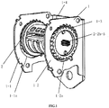
- FIG. 1 is the structure schematic view of the first embodiment for the winder used for a safety belt
- FIG. 2 is the structure schematic view for the reel in the FIG. 1
- FIG. 3 is the cutaway view of FIG. 2 in axial direction of the reel
- FIG. 4 is the exploded view of the reel members.
- the winder comprises a winder frame 1, a reel 2 . (shown in FIG. 4 ).
- the winder frame 1 shows U-shaped, comprising two opposite sidewalls: the first sidewall 1-1 and the second sidewall 1-2, further comprises the third sidewall 1-4 connecting the first sidewall and the second sidewall.
- the first sidewall 1-1 and the second sidewall 1-2 respectively have the first round opening 1-1a and the second round opening 1-2a provided on corresponding positions, the two openings having toothed segments provided at the same positions ( FIG. 1 just shows situation of toothed segment provided in the second opening).
- the toothed segment 1-3 is used for locking the reel by means of coupling with the frame teeth, so the teeth segment 1-3 is provided at a corresponding position where the fabric belt wound on the reel is driven outwardly.
- the fabric belt is pulled outwardly from the inner side and the upper portion of the third sidewall 1-4, so the toothed segment is provided on the top portion of the two openings.
- the locking position is positioned to ensure locking is always in the same position and in the direction of force when the safety belt is in use." Providing such a controlled locking position has the advantage of overcoming flexible locking of the winder in the background art.
- the external teeth on the reel are starter teeth towards reel rotating direction
- the teeth on the winder frame 1 has starter teeth whose tooth direction is opposite to that on the reel 2, which guide the reel 2 on both sides to lock correctly during the locking process.
- the reel 2 comprising the spindle 2-1 and the detachable end covers provided on two ends of the spindle 2-1: the left side end cover 2-2a and the right side end cover 2-2b.
- the spindle 2-1 is used for winding the fabric belt of the seatbelt.
- the fabric belt can freely wind in and out around the circumference of the spindle during normal use.
- the spindle has a through hole 2-3 provided along its axis, the through hole has internal teeth used for fitment of the torsion bar / bars, in the inner wall, the through hole also allows for the fixation of the fabric belt 2-4 (seeing FIG 10 )
- the two end faces of the spindle 2-1 respectively have shear pins provided thereon, the shear pins extend outwardly from the spindle face.
- the two end covers have external teeth provided on their peripheries: external teeth 2-2a-1 provided on the periphery of left side end cover 2-2a, external teeth 2-2b-1 provided on the periphery of right side end cover 2-2b, and the teeth on the two said end covers engage with the frame teeth when the safety belt locking process takes place.
- the faces of the two end covers which face the spindle 2-1 have pin orifices provided at positions where they correspond to the positions of the shear pins on the spindle 2-1, such as pin orifice 2-2b-2 in the right end cover 2-2b showed in FIG. 4 .
- Shear pins are inserted into corresponding pin orifices when the two end covers are assembled to the spindle 2-1 as shown in FIG. 2 .
- shear pins can also be arranged at the internal side of the end cover, while the pin opening could be provided at a corresponding position of the end face of the spindle 2-1.Positions of the shear pins at two ends of the spindle can be different, which could be used to fix the position when the end cover and spindle 2-1 are assembled, preventing left and right end covers from being wrongly assembled.
- the shear pins 2-6 can also bear a force from the rotating of the spindle, and be cut off when the shear force reaches a threshold value.
- the center end faces of the two end covers which face the spindle 2-1 further have center concave orifices (hereinafter referred to as the concave orifice) provided thereon, such as concave orifice 2-2b-3/4 on right end cover 2-2b showed in FIG. 4 .
- concave orifices of the two end covers are provided on the bosses which extend outside of the end covers; Accordingly, spigots used for containing the bosses on end faces of the spindle are provided on their end faces.
- External sides of the two end covers (side of the end cover which is far away from spindle 2-1), have projecting shafts provided along the center of the end cover, the shafts extending outwardly, such as the right projecting shaft 2-2b-5 in FIG. 1 , and the left projecting shaft 2-2a-5 in FIG. 4 .
- the left projecting shaft 2-2a-5 connects with the mechanism side of the safety belt
- the right projecting shaft 2-2b-5 connects with a coil spring.
- the winder further comprises a torsion bar 3 showed in FIG. 4 which shows a rod-shaped bar, the torsion bar having external teeth provided in the middle and on it's two ends.
- the structure of the torsion bar 3 and the spindle 2 are shown in FIG. 2, FIG. 3 , and FIG. 4 ; the torsion bar 3 is inserted into the through hole 2-3 of the spindle 2-1, with external teeth in axial direction the middle portion engaged with internal teeth provided in the internal wall of the through hole 2-3 of the spindle.
- the left side end cover 2-2a and the right side end cover 2-2b cover two end portions of the spindle 2-1 respectively from the left and the right sides, and the corresponding shear pins correspond to the pin orifices.
- Two ends of the torsion bar 3 fit into the corresponding teeth provided on the left and right side end covers 2-2a and 2-2b respectfully. (see FIG's 13,14 & 15)
- the bearing ring 4a is further provided between the bosses of the two end covers and the spigot of the spindle 2-1; the bearing ring 4b is made from a low friction plastic, the bearings prevent a metal to metal rubbing which could cause a gluing / sticking effect between the spigot and the end cap covers during rotation.
- the end cover is provided along outboard edge thereof with a circular boss( fig4 shows a circular boss 2-2b-6 on the right end cover).
- the spindle 2-1 is provided on the corresponding position of the facing ends thereof with an avoidance spigot which matches the circular boss.
- the reel 2 is assembled inside the frame 1, through the frame side wall openings.
- the reel 2 In a fully assembled state, the reel 2 can rotate and float in the winder frame 1, wherein the external teeth on the end covers do not touch the internal teeth in the opening of the winder frame 1.
- the reel 2 is supported by a projecting shaft provided on the outer sides of the two end covers, and the reel 2 can rotate freely, when winding and releasing the fabric belt.
- the external teeth on the two end covers of the reel 2 While in a locked state, the external teeth on the two end covers of the reel 2 are engaged with the teeth at a corresponding position of the frame 1, preventing the reel 2 from rotating.
- the opening in the frame has a toothed area 1-3, which corresponds to the direction of travel of the webbing when being extracted.
- this section 1-3 guarantees the reel is always locked in a fixed and controlled position.
- two end covers of the reel have two ends of the torsion bar 3 fitted, the two ends do not extend outside of the end covers, namely the length of the torsion bar in axis direction is not longer than the length of the reel in axial direction.
- the torsion bar in the present embodiment is shortened, and the shortened portion is replaced by the projecting shaft provided on the outer side of the end cover.
- the torsion bar 3 supports the traction from the webbing belt by means of peripheral external teeth in the middle portion being engaged with internal teeth of the spindle 2-1, while the two ends are fixed because of the meshing relationship between the external teeth on the torsion bar ends meshed with the teeth in the inner face of the end cover 2-2; when the traction from fabric belt reaches to certain value, the torsion bar 3 distorts and deflects, making the spindle 2-1 rotate at a certain angle, thus releasing partial fabric belt; this property of distorting and deflecting of the torsion bar 3 can release the fabric belt properly, making the force of the fabric belt on the human body controlled at a predetermined value, avoiding injury to the human body by avoiding large forces; meanwhile, the fabric belt will not be released overlong, which makes the fabric lose effect of binding human body.
- the length of the torsion bar is shortened so that the torsion bar is not easy to distort and deflect, and not be restrained by other members except the end covers at two sides; the whole force condition of the torsion bar is simplified, and the using process is more safe and sustainable; incidentally, the torsion bar is not easy to distort and deflect so that relative angle between the spindle and the end cover is kept, thus not causing partial metal fraction and agglutination between the spindle and the end cover.
- the torsion bar because of the shortened length of the torsion bar, and the position of the boss in the internal side of the end cover and the spigot in the spindle, the torsion bar just supports the force from the spindle and counter-acting force from the end cover, and does not support the traction from the webbing directly, so the force condition of the torsion bar is easier to control, making it possible to design force limiting pins which meet the required force limits.
- the design of the central segment of the torsion bar makes the distribution of the force equal on both sides of the bar, allowing for a smaller diameter bar to meet requirements.
- the material and process to manufacture a torsion bar is high, so a shorter torsion bar has the added advantage of cost savings.
- the force limiting pins 2-6 provided on the two ends of the spindle of the reel 2 described as above; when the reel 2 is in a locked state, driven by the safety belt webbing, the spindle 2-1 tends to rotate with the two end covers, then the force limiting pin 2-6 and the external teeth 3-1 in middle portion of the torsion bar will prevent it from rotating.
- the force limiting pin 2-6 is subject to a shear force from the end cover and the spindle 2-1. When a collision happens, there is a loading procedure of traction from the fabric belt rapidly producing a high load.
- the torsion bar does not take any load, but when the force is higher than the shear force of the pins the pins will fracture and the torsion bar 3 takes the load completely, producing a process of distortion and deflection of the torsion bar 3.
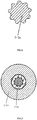
- the middle portion of external teeth of the torsion bar 3 has a missing tooth area, which is called an avoiding tooth, such as the avoiding tooth 3-1-1 shown in FIG. 11 and FIG. 5 .
- FIG. 10 is the collaboration diagrammatic drawing of the external teeth coupling within the spindle through hole when the torsion bar with the missing tooth in the middle portion is inserted into the spindle. It can be seen from the FIG. 10 that the position and design of the avoiding tooth 3-1-1 in the torsion bar 3 allows fitment of the fabric belt. The position and design of the spindle through hole ensures that the direction of the fabric belt is perpendicular to the center shaft of the spindle 2-1, and as close as possible to the center shaft.
- the torsion bar 3 also has a missing tooth for preventing errors of assembly; as shown in FIG.5 , one end of the torsion bar (taking the right end for example in the present embodiment) has a missing tooth for preventing the error of assembling 3-2b-1, while the other end does not have a missing tooth, ensuring that the torsion bar can only be fitted in one direction through the spindle through hole. Accordingly, the end cover 2-2b has a boss with the matching female profile to the missing tooth. As showed in FIG. 4 , the concave hole 2-2b-3 of the end cover 2-2b has a corresponding mouth for preventing error of assembling 2-2b-4.
- the reason of the above settings of missing tooth for preventing error of assembling is that it 3-2b-1 can guarantee that the torsion bar 3 is inserted into the through opening 2-3 of the spindle successfully at a time, which needs to be inserted into it at proper angle because of the existence of the above avoiding tooth 3-1-1.
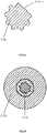
- FIG. 6 is the tooth profile of the left side end of the torsion bar in FIG. 5 ;
- FIG. 7 is the collaboration diagram of the left end of the torsion bar being inserted into the concave hole in the left end cover;
- FIG. 8 the tooth profile of right end of the torsion bar in FIG. 5 ;
- FIG. 9 is the collaboration diagram of the right end of the torsion bar being inserted into the concave hole in the right end cover;
- the difference of the winder in the present embodiment from the above first embodiment is that its torsion bar has a structure of two segments, as shown in FIG. 13 . the exploded view of the reel in the second embodiment;
- the torsion bar comprises two bars whose axial lengths are the same: the first rod 3a and the second rod 3b, the end portion of each rod having external teeth provided in axial direction.
- the two segments When the two segments are installed into the torsion bar, two adjoining ends and two adjoining end faces of the two bars are connected to each other, and corresponding teeth corresponds to each other without staggered teeth; the whole external teeth on the jointing portion of the two ends are treated equivalently to the peripheral external teeth in the middle portion of the torsion bar whose function and connection type with the spindle is the same as that in the first embodiment.
- the other ends of the two bars are inserted into the corresponding concave holes on the inside face of the end covers, as described in the first embodiment.
- the external teeth on the jointing portion of the two bars have the same avoiding teeth as described in the first embodiment.
- the division of the torsion bar into two segments has the following effects: the combination of two bar segments of the same diameter or different diameters can generate multiple force-limiting values, thus forming a winder with multiple force-limiting values by using less torsion bars, and satisfying different requirements of force-limiting values of the safety belt from different car manufacturers, FIG. 14 shows two torsion bars of the same diameter and FIG. 15 shows two torsion bars of different diameters.
- each torsion bar of different diameters needs to be made by one individual mold which is very expensive, and the torsion bar is made from special materials and by means of a cold forming process, whose manufacturing device is very expensive; adapting a torsion bar with two segments can obtain multiple force limiting values required by combination of the torsion bar manufactured by less manufacturing molds , thus reducing the number of the moulds and saving in manufacturing costs.
- the shorter torsion bar is easy to be made, with high percentage of pass, and the cost for each mold is relatively lower.
- the change of the torsion bar material and the change of the diameter can be conducted simultaneously, making many combinations of different force-limiting values, which will not be described any more now.
- the torsion bar is divided into two segments in the same way as that in the second embodiment;
- FIG. 16 is the structure schematic view of one of the bar segment of the torsion bar in the third embodiment;
- FIG. 17 is the cutaway view of the two segments of the torsion bar assembled with the other members of the reel in the third embodiment;
- the torsion bar shows two bars divided into two segments in axial direction, two ends of each segment having peripheral external teeth provided thereon, please refer to FIG. 16 , two ends of bar segment 3a having external teeth 3a-1 and 3a-2 provided thereon.
- the two bar segments of the torsion bar whose ends abut against each other with end face respectively being in touch with each other and with outer teeth thereon aligning to each other not offsetting form the whole torsion bar.
- the effective lengths of two rods of the torsion bar are different; the effective length defines the axial length of the torsion bar excluding the axial length of the external teeth.
- the first bar segment 3a is longer than the second segment 3b, which is purposely designed instead of manufacturing error.
- the other structures in the present embodiment are the same as those in the above second embodiment, which will not be described any more.
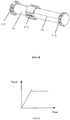
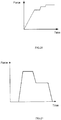
- the axial effective lengths of the two rods at each side of the peripheral external teeth in the middle portion of the torsion bar are different; when the torsion bar is used for a safety belt during a crash, the rod whose effective length is shorter breaks and loses effect first, due to the larger distortion, followed by the 2nd rod, before the shorter rod breaks the 2 rods are working as a single torsion bar with a relatively high load, after breakage of the shorter rod the longer rod continues to rotate at a smaller load, giving a 2 stage load limiting from high to low.(see FIG 21 )
- the force limited safety assembly in the first and second embodiments is constant force load limiting types, also referred to as one level or single level force limiters, whose property curves can be seen in FIG 19 .
- torsion bar material and the change of diameter can be conducted simultaneously making more combinations of load limiting, which will not be described any more now.
- the effective length and diameter of the two rods in FIG. 17 are different.
- the winder used for a safety belt also comprises a frame, a reel, and a torsion bar, wherein, the frame is the same as that in the first embodiment.
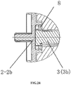
- the reel is shown in FIG. 22, 23 and 24 , wherein, FIG. 22 is the exploded view of the reel and the members of the torsion bar in the fifth embodiment; FIG. 23 is the cutaway view of the reel in axial direction in the fifth embodiment; FIG. 24 is the partially enlarged view of the FIG. 23 .
- the reel 2 comprises a spindle 2-1 and end covers positioned detachably at both ends of the spindle 2-1: the first end cover 2-2a and the second end cover 2-b.
- the structure of the first end cover 2-2a and its assembly relationship with the spindle 2-1 are the same as those in the first and second embodiments.
- the center of the end face of the second end cover 2-2b which faces the spindle 2-1 has a threaded orifice 2-2b-3, the threaded orifice having an internal thread provided therein, the threaded orifice 2-2b-3 being a blind orifice.
- the threaded orifice 2-2b-3 is provided on boss 2-2b-4 which extends from the inside of the end face, as showed in FIG. 22 , accordingly, a spigot for containing the boss 2-2b-4 needs to be provided on the corresponding end face of the spindle 2-1.
- the torsion bar 3 of the winder is divided into two segments in axial direction, which are called the first bar segment 3a and the second bar segment 3b, the two ends of the bar segments having external teeth positioned thereon.
- the two adjoining ends of the two bar segments connect to each other, and the two adjoining ends come face to face with each other, the external teeth on two ends correspond to each other without staggered teeth when the two bar segments are assembled as a whole torsion bar.
- the external teeth on the jointing portion of the two ends of the torsion bar couple with the internal teeth in the through hole of the spindle 2-1, as shown in FIG. 22 .
- the external teeth on one of the outside ends of the torsion bar couple with the internal teeth in the on the first end cover 2-2a of the winder in the present embodiment, while the external teeth on the other end couple with the internal teeth in the internal opening 8-1 of the circular toothed ring 8 shown in FIG. 22 .
- the length of the torsion bar 3 in the axial direction is not longer than the length of the reel of the winder in axial direction.
- the internal opening of the circular toothed ring 8 has internal teeth positioned, the internal teeth coupling with one outside end of the torsion bar; the periphery of the circular toothed ring also has an external thread positioned thereon, the external thread coupling with the internal thread on thread hole 2-2b-3 on the second end cover 2-2b.
- the torsion bar 3 When the device is assembled, the torsion bar 3 is inserted into the through hole 2-3 of the spindle 2-1, external teeth on the middle portion in axial direction being engaged with the internal teeth positioned in the inside wall of the through hole 2-3 of the spindle.
- the first end cover and the second end cover cover the two ends of the spindle 2-1 respectively, and accordingly the shear pins corresponds to the pin orifice.
- One end of the torsion bar 3 is inserted into the spindle through hole of the first end cover 2-2a, external teeth on the end being engaged with the internal teeth of corresponding boss on the end cover, while the other end is inserted into the internal orifice of the circular toothed ring 8, and engaged with the internal teeth therein.
- the circular toothed ring 8 screws in the thread hole 2-2b-3 on the second end cover 2-2b through its periphery thread, forming a part of the second end cover 2-2b, and the thread is not screwed wholly with the predetermined circles left(such as one to two circles).
- one end of the torsion bar 3 is engaged with the first end cover 2-2a by connecting the external tooth profile of the bar with an internal tooth profile on the end cover, and the other end is screwed with the second end cover 2-2b by the circular toothed ring 8.
- the reel is wholly provided in the frame at the same way as that in the above first embodiment.
- the working process of the winder in the present embodiment is as follows: when a collision occurs, the fabric belt drives the spindle 2-1 rotating, the peripheral external teeth on the middle portion of the torsion bar 3 are engaged with the internal teeth of the spindle, making the torsion bar support traction from the fabric belt and rotate; when the fabric belt is fastened, the two end covers of the spindle 2-1 are locked on the frame, wherein, the first end cover 2-2a is engaged with one end cover of torsion bar 3, making this end of the torsion bar fixed and unable to rotate, and the another end is screwed with the second end cover by the circular toothed ring , being able to rotate because of predetermined thread circles; that is to say, when the traction from the fabric belt reaches the first force limiting value, the end engaged with the first end cover is locked, while the end screwed with the second the end cover and the whole torsion bar can rotate moderately,
- a safety belt having the above increasing force-limiting safety device offers better protection, when a crash occurs, the lower force-limiting allows the occupant to move forward with lower forces on the body and the increased load-limiting slows down forward movement, reducing the risk of serious injury.
- the torsion bar 3 is made up of 2 bars whose effective lengths are different, the diameters and materials of the two bar segments can also be different.
- the use of different combinations of length, material and diameters of bars can give a large variety of loading curves, which would not be possible with a one bar solution.
- the end of torsion bar 3 is screwed with the second end cover 2-2b by the circular toothed ring 8 which is engaged with the end.
- the circular toothed ring 8 can be deleted and incorporated directly in the end cover, with external thread coupling.
- the torsion bar is illustrated by using a torsion bar not extending outside of the two end covers of the reel as example, however, those skilled in the art should understand that the torsion bar recorded in the background art can also be used in the present invention, so the axial length of the torsion bar is longer than the axial length of the winder. Accordingly, the end covers would need to be designed with openings through their centers, which will not be further described.
- the present invention further claims a safety belt assembly which uses the winder in the above embodiment, and can obtain the beneficial effects brought by the winder in the above embodiment.
- a safety belt assembly which uses the winder in the above embodiment, and can obtain the beneficial effects brought by the winder in the above embodiment.
Landscapes
- Engineering & Computer Science (AREA)
- Mechanical Engineering (AREA)
- Automotive Seat Belt Assembly (AREA)
Claims (1)
- Sicherheitsgurtwickler mit einem Torsionsstab (3), der für den Sicherheitsgurtwickler verwendet wird, wobei der Torsionsstab (3) in Form eines Stabes ist, der mit umlaufenden Außenzähne (3a-1, 3a-2) versehen ist, und die Außenverzahnungen an den beiden Enden des Torsionsstabes (3) konfiguriert sind, um mit Innenverzahnungen in einem Schrumpfloch an den Stirnseiten von Endabdeckungen (2-2a; 2-2b) des Sicherheitsgurtwicklers in Eingriff zu kommen;
wobei der Torsionsstab (3) in axialer Richtung in zwei Segmente (3a, 3b) unterteilt ist, wobei die beiden Segmente (3a, 3b) miteinander verbunden sind und den Torsionsstab (3) bilden, wobei die Außenzähne (3a-1, 3a-2) an zwei Enden beider Stabsegmente (3a, 3b) und die Zahnprofile der Außenzähne (3a-1, 3a-2) an dem angrenzenden Abschnitt der beiden Stabsegmente (3a, 3b) miteinander ausgerichtet sind; periphere Außenzähne auf dem angrenzenden Abschnitt der beiden Stabsegmente (3a, 3b), die die Außenzähne (3-1-2) bilden, die auf dem mittleren Abschnitt (3-1) des Torsionsstabes (3) vorgesehen sind,
die axiale wirksame Länge von zwei Stabsegmenten (3a, 3b) an zwei Seiten der peripheren Außenzähne im mittleren Abschnitt (3-1) des Torsionsstabes (3) ist unterschiedlich; wobei sich die wirksame Länge auf die axiale Länge der Torsionstabsegmente (3a, 3b) bezieht, mit Ausnahme der axialen Länge der Außenzähne (3a-1, 3a-2) an den beiden Enden; dadurch gekennzeichnet, dass die Außenzähne (3-2a, 3-2b) die beiden Enden des Torsionsstabes (3) so bilden, dass sich der Torsionsstab (3) nicht über die Außenzähne (3-2a) an einem ersten Ende und die Außenzähne (3-2b) an einem zweiten Ende hinaus erstreckt;
wodurch die Anzahl der am zweiten Ende vorgesehenen Außenzähne (3-2b) kleiner ist als die Anzahl der am ersten Ende vorgesehenen Außenzähne (3-2a), und ein Bereich mit einem fehlenden Zahn (3-2b-1) am zweiten Ende gebildet wird, der sicherstellt, dass der Torsionsstab nur in eine Richtung angepasst werden kann.
Applications Claiming Priority (7)
| Application Number | Priority Date | Filing Date | Title |
|---|---|---|---|
| CN201210308979.XA CN102837663B (zh) | 2012-08-27 | 2012-08-27 | 用于安全带卷收器的扭力杆及安全带卷收器、安全带总成 |
| CN201210309026.5A CN102923091B (zh) | 2012-08-27 | 2012-08-27 | 用于安全带卷收器的扭力杆及安全带卷收器、安全带总成 |
| CN201210309066.XA CN102837664B (zh) | 2012-08-27 | 2012-08-27 | 一种用于安全带的卷收器和安全带总成 |
| CN201210309320.6A CN102837665B (zh) | 2012-08-27 | 2012-08-27 | 卷轴、端盖、安全带卷收器和安全带总成 |
| CN201210496376.7A CN103847684B (zh) | 2012-11-29 | 2012-11-29 | 用于安全带卷收器的扭力杆、安全带卷收器及安全带总成 |
| CN201310032779.0A CN103963737B (zh) | 2013-01-29 | 2013-01-29 | 用于安全带的卷收器、端盖、环形齿圈和安全带总成 |
| PCT/CN2013/082175 WO2014032546A1 (zh) | 2012-08-27 | 2013-08-23 | 一种用于安全带的卷收器、扭力杆、卷轴、端盖和安全带总成 |
Publications (3)
| Publication Number | Publication Date |
|---|---|
| EP2889191A1 EP2889191A1 (de) | 2015-07-01 |
| EP2889191A4 EP2889191A4 (de) | 2016-08-31 |
| EP2889191B1 true EP2889191B1 (de) | 2019-10-02 |
Family
ID=50182493
Family Applications (1)
| Application Number | Title | Priority Date | Filing Date |
|---|---|---|---|
| EP13833997.3A Active EP2889191B1 (de) | 2012-08-27 | 2013-08-23 | Aufwickelvorrichtung für einen sicherheitsgurt, torsionsstab, spule, endkappe und sicherheitsgurtanordnung |
Country Status (3)
| Country | Link |
|---|---|
| US (1) | US9718437B2 (de) |
| EP (1) | EP2889191B1 (de) |
| WO (1) | WO2014032546A1 (de) |
Families Citing this family (7)
| Publication number | Priority date | Publication date | Assignee | Title |
|---|---|---|---|---|
| DE102014015932B4 (de) * | 2014-10-30 | 2020-02-13 | Trw Automotive Gmbh | Sicherheitsgurtaufroller |
| GB2564707B (en) * | 2017-07-21 | 2022-02-23 | Nissan Motor Mfg Uk Ltd | Twin shoulder strap harness retractor assembly |
| CN107791998B (zh) * | 2017-12-08 | 2024-02-20 | 沈阳金杯锦恒汽车安全系统有限公司 | 一种安全带卷收器芯轴组件结构 |
| EP3514022A1 (de) * | 2018-01-19 | 2019-07-24 | TRW Polska Sp.z.o.o. | Gurtrolle und gurtaufroller |
| US10759381B2 (en) * | 2018-08-20 | 2020-09-01 | Ford Global Technologies, Llc | Vehicle seat belt retractor |
| CN115703426A (zh) * | 2021-08-13 | 2023-02-17 | 宏霖工业股份有限公司 | 卷轴组件 |
| DE102022114835A1 (de) * | 2022-06-13 | 2023-12-14 | Autoliv Development Ab | Gurtaufroller für einen Sicherheitsgurt eines Kraftfahrzeuges |
Family Cites Families (13)
| Publication number | Priority date | Publication date | Assignee | Title |
|---|---|---|---|---|
| US5785269A (en) * | 1997-02-06 | 1998-07-28 | Alliedsignal Inc. | Dual level retractor for oblique or offset impacts |
| US5799893A (en) * | 1997-02-19 | 1998-09-01 | Alliedsignal Inc. | Multi-level load limiting torsion bar retractor |
| US5967441A (en) * | 1997-07-22 | 1999-10-19 | Breed Automotive Technology, Inc. | Seat belt retractor with torsion bar and rotation limit |
| US6012667A (en) * | 1998-02-19 | 2000-01-11 | Breed Automotive Technology Inc. | Multi-level load limiting torsion bar retractor |
| DE29803178U1 (de) * | 1998-02-23 | 1998-06-18 | Trw Repa Gmbh | Gurtaufroller für einen Fahrzeuginsassen-Sicherheitsgurt |
| EP1607288B1 (de) * | 2004-06-14 | 2007-08-15 | Chris Cintos de Seguranca Ltda. | Sicherheitsvorrichtung |
| US7669794B2 (en) * | 2004-09-01 | 2010-03-02 | Key Safety System, Inc | Seatbelt retractor with torsion bar |
| US7410114B2 (en) * | 2006-09-12 | 2008-08-12 | Delphi Technologies, Inc. | Compact dual-level load limiting seat belt retractor |
| JP4953835B2 (ja) * | 2007-01-17 | 2012-06-13 | オートリブ ディベロップメント エービー | シートベルト用リトラクタ |
| WO2010119778A1 (ja) * | 2009-04-17 | 2010-10-21 | オートリブ ディベロップメント エービー | シートベルト用リトラクタ |
| US8220735B2 (en) * | 2009-12-22 | 2012-07-17 | Autoliv Asp, Inc. | Adaptive load limiting retractor |
| CN202743196U (zh) * | 2012-08-27 | 2013-02-20 | 上海和励信息科技有限公司 | 一种用于安全带的卷收器和安全带总成 |
| CN102837664B (zh) * | 2012-08-27 | 2016-01-13 | 上海和励信息科技有限公司 | 一种用于安全带的卷收器和安全带总成 |
-
2013
- 2013-08-23 EP EP13833997.3A patent/EP2889191B1/de active Active
- 2013-08-23 US US14/421,457 patent/US9718437B2/en active Active
- 2013-08-23 WO PCT/CN2013/082175 patent/WO2014032546A1/zh active Application Filing
Non-Patent Citations (1)
| Title |
|---|
| None * |
Also Published As
| Publication number | Publication date |
|---|---|
| EP2889191A4 (de) | 2016-08-31 |
| WO2014032546A1 (zh) | 2014-03-06 |
| EP2889191A1 (de) | 2015-07-01 |
| US20150210247A1 (en) | 2015-07-30 |
| US9718437B2 (en) | 2017-08-01 |
Similar Documents
| Publication | Publication Date | Title |
|---|---|---|
| EP2889191B1 (de) | Aufwickelvorrichtung für einen sicherheitsgurt, torsionsstab, spule, endkappe und sicherheitsgurtanordnung | |
| JPS6111085Y2 (de) | ||
| JP5199197B2 (ja) | ウェビング巻取装置 | |
| US7744029B2 (en) | Belt spool | |
| JP6198746B2 (ja) | シートベルトリトラクタ | |
| WO2013021787A1 (ja) | シートベルトのリトラクタ装置及びシートベルト装置 | |
| US7661712B2 (en) | Seat belt retractor | |
| US9212024B2 (en) | Webbing retractor | |
| CN202743198U (zh) | 卷轴、端盖、安全带卷收器和安全带总成 | |
| JP5961570B2 (ja) | ウェビング巻取装置 | |
| US6264127B1 (en) | Seat belt retractor | |
| JP4859131B2 (ja) | シートベルトリトラクタおよびこれを備えたシートベルト装置 | |
| CN103963737B (zh) | 用于安全带的卷收器、端盖、环形齿圈和安全带总成 | |
| US11338767B2 (en) | Seatbelt retractor | |
| US20170291571A1 (en) | Webbing take-up device | |
| KR101492900B1 (ko) | 프로그레시브 로드 리미터 | |
| CN202743199U (zh) | 用于安全带卷收器的扭力杆及安全带卷收器、安全带总成 | |
| CN103847684B (zh) | 用于安全带卷收器的扭力杆、安全带卷收器及安全带总成 | |
| CN110525374B (zh) | 限力式芯轴及安全带卷收器 | |
| KR101477608B1 (ko) | 로드 리미터 | |
| JP5210125B2 (ja) | ウエビング巻取装置 | |
| JP4153929B2 (ja) | シートベルトリトラクタ | |
| CN102923091A (zh) | 用于安全带卷收器的扭力杆及安全带卷收器、安全带总成 | |
| CN102717772B (zh) | 安全带卷收器 | |
| KR20210133077A (ko) | 스풀의 회전속도에 따라 작동구간이 조절되는 로드리미터 |
Legal Events
| Date | Code | Title | Description |
|---|---|---|---|
| PUAI | Public reference made under article 153(3) epc to a published international application that has entered the european phase |
Free format text: ORIGINAL CODE: 0009012 |
|
| 17P | Request for examination filed |
Effective date: 20150326 |
|
| AK | Designated contracting states |
Kind code of ref document: A1 Designated state(s): AL AT BE BG CH CY CZ DE DK EE ES FI FR GB GR HR HU IE IS IT LI LT LU LV MC MK MT NL NO PL PT RO RS SE SI SK SM TR |
|
| AX | Request for extension of the european patent |
Extension state: BA ME |
|
| DAX | Request for extension of the european patent (deleted) | ||
| RIC1 | Information provided on ipc code assigned before grant |
Ipc: B60R 22/34 20060101AFI20160512BHEP |
|
| RA4 | Supplementary search report drawn up and despatched (corrected) |
Effective date: 20160802 |
|
| RIC1 | Information provided on ipc code assigned before grant |
Ipc: B60R 22/34 20060101AFI20160727BHEP |
|
| STAA | Information on the status of an ep patent application or granted ep patent |
Free format text: STATUS: EXAMINATION IS IN PROGRESS |
|
| 17Q | First examination report despatched |
Effective date: 20170620 |
|
| GRAP | Despatch of communication of intention to grant a patent |
Free format text: ORIGINAL CODE: EPIDOSNIGR1 |
|
| STAA | Information on the status of an ep patent application or granted ep patent |
Free format text: STATUS: GRANT OF PATENT IS INTENDED |
|
| INTG | Intention to grant announced |
Effective date: 20190402 |
|
| GRAS | Grant fee paid |
Free format text: ORIGINAL CODE: EPIDOSNIGR3 |
|
| GRAA | (expected) grant |
Free format text: ORIGINAL CODE: 0009210 |
|
| STAA | Information on the status of an ep patent application or granted ep patent |
Free format text: STATUS: THE PATENT HAS BEEN GRANTED |
|
| RAP1 | Party data changed (applicant data changed or rights of an application transferred) |
Owner name: HELIA TECHNOLOGY LIMITED |
|
| AK | Designated contracting states |
Kind code of ref document: B1 Designated state(s): AL AT BE BG CH CY CZ DE DK EE ES FI FR GB GR HR HU IE IS IT LI LT LU LV MC MK MT NL NO PL PT RO RS SE SI SK SM TR |
|
| REG | Reference to a national code |
Ref country code: GB Ref legal event code: FG4D |
|
| REG | Reference to a national code |
Ref country code: CH Ref legal event code: EP Ref country code: AT Ref legal event code: REF Ref document number: 1185836 Country of ref document: AT Kind code of ref document: T Effective date: 20191015 |
|
| REG | Reference to a national code |
Ref country code: DE Ref legal event code: R096 Ref document number: 602013061306 Country of ref document: DE |
|
| REG | Reference to a national code |
Ref country code: IE Ref legal event code: FG4D |
|
| REG | Reference to a national code |
Ref country code: NL Ref legal event code: MP Effective date: 20191002 |
|
| REG | Reference to a national code |
Ref country code: LT Ref legal event code: MG4D |
|
| REG | Reference to a national code |
Ref country code: AT Ref legal event code: MK05 Ref document number: 1185836 Country of ref document: AT Kind code of ref document: T Effective date: 20191002 |
|
| PG25 | Lapsed in a contracting state [announced via postgrant information from national office to epo] |
Ref country code: GR Free format text: LAPSE BECAUSE OF FAILURE TO SUBMIT A TRANSLATION OF THE DESCRIPTION OR TO PAY THE FEE WITHIN THE PRESCRIBED TIME-LIMIT Effective date: 20200103 Ref country code: LT Free format text: LAPSE BECAUSE OF FAILURE TO SUBMIT A TRANSLATION OF THE DESCRIPTION OR TO PAY THE FEE WITHIN THE PRESCRIBED TIME-LIMIT Effective date: 20191002 Ref country code: BG Free format text: LAPSE BECAUSE OF FAILURE TO SUBMIT A TRANSLATION OF THE DESCRIPTION OR TO PAY THE FEE WITHIN THE PRESCRIBED TIME-LIMIT Effective date: 20200102 Ref country code: NO Free format text: LAPSE BECAUSE OF FAILURE TO SUBMIT A TRANSLATION OF THE DESCRIPTION OR TO PAY THE FEE WITHIN THE PRESCRIBED TIME-LIMIT Effective date: 20200102 Ref country code: SE Free format text: LAPSE BECAUSE OF FAILURE TO SUBMIT A TRANSLATION OF THE DESCRIPTION OR TO PAY THE FEE WITHIN THE PRESCRIBED TIME-LIMIT Effective date: 20191002 Ref country code: PT Free format text: LAPSE BECAUSE OF FAILURE TO SUBMIT A TRANSLATION OF THE DESCRIPTION OR TO PAY THE FEE WITHIN THE PRESCRIBED TIME-LIMIT Effective date: 20200203 Ref country code: AT Free format text: LAPSE BECAUSE OF FAILURE TO SUBMIT A TRANSLATION OF THE DESCRIPTION OR TO PAY THE FEE WITHIN THE PRESCRIBED TIME-LIMIT Effective date: 20191002 Ref country code: FI Free format text: LAPSE BECAUSE OF FAILURE TO SUBMIT A TRANSLATION OF THE DESCRIPTION OR TO PAY THE FEE WITHIN THE PRESCRIBED TIME-LIMIT Effective date: 20191002 Ref country code: LV Free format text: LAPSE BECAUSE OF FAILURE TO SUBMIT A TRANSLATION OF THE DESCRIPTION OR TO PAY THE FEE WITHIN THE PRESCRIBED TIME-LIMIT Effective date: 20191002 Ref country code: NL Free format text: LAPSE BECAUSE OF FAILURE TO SUBMIT A TRANSLATION OF THE DESCRIPTION OR TO PAY THE FEE WITHIN THE PRESCRIBED TIME-LIMIT Effective date: 20191002 Ref country code: ES Free format text: LAPSE BECAUSE OF FAILURE TO SUBMIT A TRANSLATION OF THE DESCRIPTION OR TO PAY THE FEE WITHIN THE PRESCRIBED TIME-LIMIT Effective date: 20191002 Ref country code: PL Free format text: LAPSE BECAUSE OF FAILURE TO SUBMIT A TRANSLATION OF THE DESCRIPTION OR TO PAY THE FEE WITHIN THE PRESCRIBED TIME-LIMIT Effective date: 20191002 |
|
| PG25 | Lapsed in a contracting state [announced via postgrant information from national office to epo] |
Ref country code: IS Free format text: LAPSE BECAUSE OF FAILURE TO SUBMIT A TRANSLATION OF THE DESCRIPTION OR TO PAY THE FEE WITHIN THE PRESCRIBED TIME-LIMIT Effective date: 20200224 Ref country code: CZ Free format text: LAPSE BECAUSE OF FAILURE TO SUBMIT A TRANSLATION OF THE DESCRIPTION OR TO PAY THE FEE WITHIN THE PRESCRIBED TIME-LIMIT Effective date: 20191002 Ref country code: HR Free format text: LAPSE BECAUSE OF FAILURE TO SUBMIT A TRANSLATION OF THE DESCRIPTION OR TO PAY THE FEE WITHIN THE PRESCRIBED TIME-LIMIT Effective date: 20191002 Ref country code: RS Free format text: LAPSE BECAUSE OF FAILURE TO SUBMIT A TRANSLATION OF THE DESCRIPTION OR TO PAY THE FEE WITHIN THE PRESCRIBED TIME-LIMIT Effective date: 20191002 |
|
| PG25 | Lapsed in a contracting state [announced via postgrant information from national office to epo] |
Ref country code: AL Free format text: LAPSE BECAUSE OF FAILURE TO SUBMIT A TRANSLATION OF THE DESCRIPTION OR TO PAY THE FEE WITHIN THE PRESCRIBED TIME-LIMIT Effective date: 20191002 |
|
| REG | Reference to a national code |
Ref country code: DE Ref legal event code: R097 Ref document number: 602013061306 Country of ref document: DE |
|
| PG2D | Information on lapse in contracting state deleted |
Ref country code: IS |
|
| PG25 | Lapsed in a contracting state [announced via postgrant information from national office to epo] |
Ref country code: RO Free format text: LAPSE BECAUSE OF FAILURE TO SUBMIT A TRANSLATION OF THE DESCRIPTION OR TO PAY THE FEE WITHIN THE PRESCRIBED TIME-LIMIT Effective date: 20191002 Ref country code: EE Free format text: LAPSE BECAUSE OF FAILURE TO SUBMIT A TRANSLATION OF THE DESCRIPTION OR TO PAY THE FEE WITHIN THE PRESCRIBED TIME-LIMIT Effective date: 20191002 Ref country code: DK Free format text: LAPSE BECAUSE OF FAILURE TO SUBMIT A TRANSLATION OF THE DESCRIPTION OR TO PAY THE FEE WITHIN THE PRESCRIBED TIME-LIMIT Effective date: 20191002 Ref country code: IS Free format text: LAPSE BECAUSE OF FAILURE TO SUBMIT A TRANSLATION OF THE DESCRIPTION OR TO PAY THE FEE WITHIN THE PRESCRIBED TIME-LIMIT Effective date: 20200202 |
|
| PLBE | No opposition filed within time limit |
Free format text: ORIGINAL CODE: 0009261 |
|
| STAA | Information on the status of an ep patent application or granted ep patent |
Free format text: STATUS: NO OPPOSITION FILED WITHIN TIME LIMIT |
|
| PG25 | Lapsed in a contracting state [announced via postgrant information from national office to epo] |
Ref country code: SM Free format text: LAPSE BECAUSE OF FAILURE TO SUBMIT A TRANSLATION OF THE DESCRIPTION OR TO PAY THE FEE WITHIN THE PRESCRIBED TIME-LIMIT Effective date: 20191002 Ref country code: IT Free format text: LAPSE BECAUSE OF FAILURE TO SUBMIT A TRANSLATION OF THE DESCRIPTION OR TO PAY THE FEE WITHIN THE PRESCRIBED TIME-LIMIT Effective date: 20191002 Ref country code: SK Free format text: LAPSE BECAUSE OF FAILURE TO SUBMIT A TRANSLATION OF THE DESCRIPTION OR TO PAY THE FEE WITHIN THE PRESCRIBED TIME-LIMIT Effective date: 20191002 |
|
| 26N | No opposition filed |
Effective date: 20200703 |
|
| PGFP | Annual fee paid to national office [announced via postgrant information from national office to epo] |
Ref country code: DE Payment date: 20200824 Year of fee payment: 8 |
|
| PG25 | Lapsed in a contracting state [announced via postgrant information from national office to epo] |
Ref country code: SI Free format text: LAPSE BECAUSE OF FAILURE TO SUBMIT A TRANSLATION OF THE DESCRIPTION OR TO PAY THE FEE WITHIN THE PRESCRIBED TIME-LIMIT Effective date: 20191002 |
|
| PG25 | Lapsed in a contracting state [announced via postgrant information from national office to epo] |
Ref country code: MC Free format text: LAPSE BECAUSE OF FAILURE TO SUBMIT A TRANSLATION OF THE DESCRIPTION OR TO PAY THE FEE WITHIN THE PRESCRIBED TIME-LIMIT Effective date: 20191002 |
|
| REG | Reference to a national code |
Ref country code: CH Ref legal event code: PL |
|
| GBPC | Gb: european patent ceased through non-payment of renewal fee |
Effective date: 20200823 |
|
| PG25 | Lapsed in a contracting state [announced via postgrant information from national office to epo] |
Ref country code: LU Free format text: LAPSE BECAUSE OF NON-PAYMENT OF DUE FEES Effective date: 20200823 Ref country code: CH Free format text: LAPSE BECAUSE OF NON-PAYMENT OF DUE FEES Effective date: 20200831 Ref country code: LI Free format text: LAPSE BECAUSE OF NON-PAYMENT OF DUE FEES Effective date: 20200831 |
|
| REG | Reference to a national code |
Ref country code: BE Ref legal event code: MM Effective date: 20200831 |
|
| PG25 | Lapsed in a contracting state [announced via postgrant information from national office to epo] |
Ref country code: FR Free format text: LAPSE BECAUSE OF NON-PAYMENT OF DUE FEES Effective date: 20200831 |
|
| PG25 | Lapsed in a contracting state [announced via postgrant information from national office to epo] |
Ref country code: IE Free format text: LAPSE BECAUSE OF NON-PAYMENT OF DUE FEES Effective date: 20200823 Ref country code: GB Free format text: LAPSE BECAUSE OF NON-PAYMENT OF DUE FEES Effective date: 20200823 Ref country code: BE Free format text: LAPSE BECAUSE OF NON-PAYMENT OF DUE FEES Effective date: 20200831 |
|
| REG | Reference to a national code |
Ref country code: DE Ref legal event code: R119 Ref document number: 602013061306 Country of ref document: DE |
|
| PG25 | Lapsed in a contracting state [announced via postgrant information from national office to epo] |
Ref country code: TR Free format text: LAPSE BECAUSE OF FAILURE TO SUBMIT A TRANSLATION OF THE DESCRIPTION OR TO PAY THE FEE WITHIN THE PRESCRIBED TIME-LIMIT Effective date: 20191002 Ref country code: MT Free format text: LAPSE BECAUSE OF FAILURE TO SUBMIT A TRANSLATION OF THE DESCRIPTION OR TO PAY THE FEE WITHIN THE PRESCRIBED TIME-LIMIT Effective date: 20191002 Ref country code: CY Free format text: LAPSE BECAUSE OF FAILURE TO SUBMIT A TRANSLATION OF THE DESCRIPTION OR TO PAY THE FEE WITHIN THE PRESCRIBED TIME-LIMIT Effective date: 20191002 |
|
| PG25 | Lapsed in a contracting state [announced via postgrant information from national office to epo] |
Ref country code: MK Free format text: LAPSE BECAUSE OF FAILURE TO SUBMIT A TRANSLATION OF THE DESCRIPTION OR TO PAY THE FEE WITHIN THE PRESCRIBED TIME-LIMIT Effective date: 20191002 |
|
| PG25 | Lapsed in a contracting state [announced via postgrant information from national office to epo] |
Ref country code: DE Free format text: LAPSE BECAUSE OF NON-PAYMENT OF DUE FEES Effective date: 20220301 |