EP4131897B1 - Elektronische vorrichtung - Google Patents
Elektronische vorrichtung Download PDFInfo
- Publication number
- EP4131897B1 EP4131897B1 EP21776839.9A EP21776839A EP4131897B1 EP 4131897 B1 EP4131897 B1 EP 4131897B1 EP 21776839 A EP21776839 A EP 21776839A EP 4131897 B1 EP4131897 B1 EP 4131897B1
- Authority
- EP
- European Patent Office
- Prior art keywords
- blocking member
- functional module
- electronic device
- opening
- housing
- Prior art date
- Legal status (The legal status is an assumption and is not a legal conclusion. Google has not performed a legal analysis and makes no representation as to the accuracy of the status listed.)
- Active
Links
Images

Classifications
-
- H—ELECTRICITY
- H04—ELECTRIC COMMUNICATION TECHNIQUE
- H04M—TELEPHONIC COMMUNICATION
- H04M1/00—Substation equipment, e.g. for use by subscribers
- H04M1/02—Constructional features of telephone sets
- H04M1/0202—Portable telephone sets, e.g. cordless phones, mobile phones or bar type handsets
- H04M1/026—Details of the structure or mounting of specific components
-
- H—ELECTRICITY
- H04—ELECTRIC COMMUNICATION TECHNIQUE
- H04M—TELEPHONIC COMMUNICATION
- H04M1/00—Substation equipment, e.g. for use by subscribers
- H04M1/02—Constructional features of telephone sets
- H04M1/0202—Portable telephone sets, e.g. cordless phones, mobile phones or bar type handsets
- H04M1/0254—Portable telephone sets, e.g. cordless phones, mobile phones or bar type handsets comprising one or a plurality of mechanically detachable modules
- H04M1/0256—Portable telephone sets, e.g. cordless phones, mobile phones or bar type handsets comprising one or a plurality of mechanically detachable modules wherein the modules are operable in the detached state, e.g. one module for the user interface and one module for the transceiver
-
- H—ELECTRICITY
- H04—ELECTRIC COMMUNICATION TECHNIQUE
- H04M—TELEPHONIC COMMUNICATION
- H04M1/00—Substation equipment, e.g. for use by subscribers
- H04M1/02—Constructional features of telephone sets
- H04M1/18—Telephone sets specially adapted for use in ships, mines, or other places exposed to adverse environment
-
- H—ELECTRICITY
- H04—ELECTRIC COMMUNICATION TECHNIQUE
- H04M—TELEPHONIC COMMUNICATION
- H04M1/00—Substation equipment, e.g. for use by subscribers
- H04M1/02—Constructional features of telephone sets
- H04M1/0202—Portable telephone sets, e.g. cordless phones, mobile phones or bar type handsets
- H04M1/026—Details of the structure or mounting of specific components
- H04M1/0264—Details of the structure or mounting of specific components for a camera module assembly
Definitions
- the present invention relates to the technical field of communications devices, and in particular, to an electronic device.
- the electronic device usually has functions such as photographing, making a call, and fingerprint recognition, and therefore can meet use requirements of a user.
- the foregoing functions of the electronic device are generally completed by corresponding functional modules such as a camera module, a receiver, and a fingerprint recognition module.
- the camera module is used as an example.
- a camera module of a current electronic device is built in.
- the camera module may be located inside the electronic device, and the camera module can enter or exit a housing of the electronic device through an opening of the housing.
- occupation of a display area by the camera module can be avoided. This is conducive to increasing a screen-to-body of the electronic device.
- the camera module in the foregoing solution can only implement forward or backward photographing of the electronic device. Therefore, a use scenario of the camera module is limited, and photographing freedom is relatively low, and consequently, a function of the camera module is limited.
- the camera module may be separated from the housing, so that a photographing function of the electronic device is not limited by a direction and an angle, thereby improving the function of the camera module.
- WO2020020132A1 discloses a mobile terminal.
- the mobile terminal includes a housing, a camera, a driving mechanism disposed in the inner cavity of the housing.
- the frame of the housing is provided with a through hole.
- the driving mechanism includes a driving body and elastic telescopic members.
- a positioning member is provided in the inner cavity.
- the elastic telescopic members are compressed between the camera and the positioning member.
- the elastic telescopic members are used for applying an elastic force to the camera so that the camera runs through the through hole.
- the driving body applies a traction force to the camera so that the camera runs through the through hole and retracts into the inner cavity.
- WO2019015651A1 discloses a mobile terminal and a camera assembly, where the mobile terminal includes a housing and the camera assembly; a through hole is provided on a frame of the housing; the camera assembly includes a camera, a support which mounts the camera, a motor and push-pull rod; the motor is fixed on the housing and is electrically connected to a circuit board of the mobile terminal; the motor is provided with a threaded rod; a first end of the push-pull rod is provided with a threaded tube which fits with the threaded rod; the threaded tube is sleeved on the threaded rod; a second end of the push-pull rod is connected to the support; when the motor drives, the threaded rod rotates and drives the push-pull rod to move forward and draw back, and the push-pull rod drives the support to move, so that the camera extends from and retracts into the housing by means of the through hole.
- the present invention discloses an electronic device, to resolve a problem of low security and reliability of an electronic device with separated functional components.
- an embodiment of the present invention discloses an electronic device, including: a housing, where the housing has an inner cavity, and the inner cavity has an opening; a functional module, where the functional module may protrude outside the inner cavity through the opening and is separated from the housing or retracted into the inner cavity; a blocking member, where the blocking member is movably disposed in the inner cavity, and the blocking member corresponds to the opening; and a driving assembly, where the driving assembly is disposed in the inner cavity, the driving assembly is connected to the blocking member, the driving assembly drives the blocking member to switch between a first state and a second state, the blocking member is away from the opening in the first state, and the blocking member blocks the opening in the second state.
- the blocking member is in the first state
- the blocking member is in the second state.
- the blocking member is movably disposed in the inner cavity, and the blocking member corresponds to the opening.
- the driving assembly drives the blocking member to switch between the first state and the second state, the blocking member is far away from the opening in the first state, and the blocking member blocks the opening in the second state.
- the blocking member is in the first state, and in a case that the functional module is separated from the housing, the blocking member is in the second state.
- the driving assembly drives the blocking member to switch to the second state.
- the blocking member may block the opening, so that dust and water vapor in an external environment do not easily enter the housing, thereby improving waterproof performance and dustproof performance of the electronic device, causing no damage to an electronic component of the electronic device, and improving security and reliability of the electronic device.
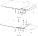
- an embodiment of the present invention discloses an electronic device, and the electronic device includes a housing 100, a functional module 200, a blocking member 400, and a driving assembly 300.
- the housing 100 provides a mounting basis for another component of the electronic device, the housing 100 has an inner cavity 110, and the inner cavity 110 has an opening 120.
- housings 100 in different structures include different components.
- the housing 100 may include a front housing, a rear cover, and a middle frame disposed between the front housing and the rear cover, the front housing, the rear cover, and the middle frame jointly form the inner cavity 110, and the opening 120 may be disposed on the front housing, may be disposed on the rear cover, or may be disposed on the middle frame.
- the housing 100 may include a front cover and a rear cover, the front cover and the rear cover jointly form the inner cavity 110, and the opening 120 may be disposed on the front cover, may be disposed on the rear cover, or may be disposed in an assembly gap between the front cover and the rear cover.
- the functional module 200 may protrude outside the inner cavity 110 through the opening 120 and be separated from the housing 100 or retracted into the inner cavity 110.
- the functional module 200 may include at least one of a camera module, a fingerprint recognition module, a receiver, a strobe light, a sensor, an unmanned aerial vehicle, or a card holder, and certainly may further include another component that needs to enter and exit the housing 100.
- the functional module 200 may protrude outside the housing 100 through the opening 120, and be separated from the housing 100. After completing working, the functional module 200 may be retracted into the housing 100 through the opening 120 on the housing 100.
- Such a functional module 200 does not occupy a display area of the electronic device.
- the functional module 200 may be separated from the housing 100, so that the functional module 200 can independently work as a functional monomer during use, and is not limited by a direction and an angle, thereby improving use flexibility of the functional module 200.
- the blocking member 400 is movably disposed in the inner cavity 110, and the blocking member 400 corresponds to the opening 120.
- the driving assembly 300 is disposed in the inner cavity 110, and the driving assembly 300 is connected to the blocking member 400.
- the blocking member 400 has a first state and a second state, and the driving assembly 300 drives the blocking member 400 to switch between the first state and the second state.
- the blocking member 400 is in the first state, and in this case, the blocking member 400 is in the inner cavity 110, and the blocking member 400 is far away from the opening 120, to avoid the functional module 200, and the functional module 200 blocks the opening 120.
- the functional module 200 is separated from the housing 100
- the blocking member 400 is in the second state, and in this case, the functional module 200 is separated from the housing 100, and the blocking member 400 blocks the opening 120.
- the driving assembly 300 may be a structure such as a linear motor or an air cylinder, and certainly, another power structure may be used. This is not limited in this specification.
- the driving assembly 300 drives the blocking member 400 to switch to the second state.
- the blocking member 400 may block the opening 120, so that dust and water vapor in an external environment do not easily enter the housing 100, thereby improving waterproof performance and dustproof performance of the electronic device, causing no damage to an electronic component of the electronic device, and improving security and reliability of the electronic device.
- the opening 120 on the housing 100 is blocked by the blocking member 400, and a user does not easily see the opening 120.
- the user has relatively weak feeling of visual impact, and therefore appearance quality of the electronic device is better, thereby improving user experience.
- a projection outline of the blocking member 400 is located within a projection outline of the opening 120.
- the blocking member 400 in a case that the blocking member 400 is in the second state, at least a part of the blocking member 400 is in the opening 120, and an edge of the blocking member 400 and an edge of the opening 120 cooperate, through limiting, in a direction in which the functional module 200 protrudes.
- the blocking member 400 may be a stepped structure, and a step surface of the blocking member 400 can fit the edge of the opening 120.
- the step surface is the edge of the blocking member 400, and the step surface can block the gap, so that dust and water vapor do not easily enter the inner cavity 110, thereby further improving security and reliability of the electronic device.
- the edge of the blocking member 400 and an inner surface of the opening 120 cooperate, through limiting, in the direction in which the functional module 200 protrudes, and the edge of the blocking member 400 interferes with the opening 120 in terms of positions, to prevent the blocking member 400 from protruding excessively from the opening 120.
- the blocking member 400 In a case that the blocking member 400 is in the second state, a part of the blocking member 400 may be higher than an outer surface of the housing 100. Consequently, an overall appearance size of the electronic device increases, and poor user experience is caused. Certainly, the outer surface of the housing 100 may also be higher than the blocking member 400, so that a groove is left at a connection between the opening 120 and the blocking member 400, and dust is easily collected in the groove, and consequently, the blocking member 400 is stuck when moving. In an optional embodiment, in a case that the blocking member 400 is in the second state, an outer surface that is of the blocking member 400 and that is exposed to the housing 100 is coplanar with the outer surface of the housing 100.
- a connection between the blocking member 400 and the opening 120 is relatively smooth, so that an appearance size of the electronic device is relatively small, thereby improving user experience.
- the user may manually drive the functional module 200 to enter or exit the inner cavity 110.
- the electronic device may further include a drive mechanism, where the drive mechanism is disposed in the inner cavity 110, the drive mechanism is connected to the functional module 200, the drive mechanism drives the functional module 200 to protrude outside the inner cavity 110 through the opening 120, and enables the functional module 200 to be separated from the housing 100, or the drive mechanism drives the functional module 200 to be retracted into the inner cavity 110 through the opening 120.
- the drive mechanism can accurately drive the functional module 200 to enter or exit the inner cavity 110.
- the user may trigger an action of the drive mechanism through remote control, to drive the functional module 200 to protrude outside the inner cavity 110 or be retracted into the inner cavity 110 through the opening 120.
- the drive mechanism may be a structure such as a drive motor, a linear motor, or an air cylinder, and the drive mechanism may alternatively be another structure for outputting power. This is not limited in this specification.
- the blocking member 400 and the functional module 200 are driven by using a corresponding power mechanism.
- mounting positions of two power mechanisms need to be reserved on the housing 100, and consequently, relatively large space of the inner cavity 110 is occupied.
- two power mechanisms are disposed in the electronic device, and consequently, costs of the electronic device are relatively high.
- the blocking member 400 in a case that the blocking member 400 is in the first state, the blocking member 400 is located on a side of the functional module 200 that is away from the opening 120, the blocking member 400 is connected to the functional module 200, the driving assembly 300 drives the blocking member 400 to move, and the functional module 200 protrudes outside the inner cavity 110 or is retracted into the inner cavity 110 through the opening 120 together with the blocking member 400.
- the blocking member 400 and the functional module 200 share one power mechanism, and only one power mechanism mounting position needs to be reserved in the inner cavity 110.
- manufacturing costs of the electronic device are relatively low, and structural design of the electronic device is more single.
- the blocking member 400 and the functional module 200 can share a power mechanism to move, and there is no need to configure a power mechanism for each of the blocking member 400 and the functional module 200. Therefore, energy consumption of the electronic device can be reduced, and a battery life of the electronic device can be prolonged.
- the functional module 200 is in contact with a surface of the blocking member 400.
- the functional module 200 and the blocking member 400 may be connected through magnetic suction, clamping, or the like.
- the functional module 200 and the blocking member 400 may move simultaneously.
- the functional module 200 can be driven to change a position. This can undoubtedly improve driving efficiency.
- the electronic device disclosed in this embodiment of the present invention may further include a detection member and a control member.
- the detection member is configured to detect position information of the functional module 200 and the blocking member 400.
- the control member may control the driving assembly 300 based on the position information.
- the driving assembly 300 drives the blocking member 400 to switch between the first state and the second state.
- the detection member detects the position information of the functional module 200 and the blocking member 400.
- the control member controls the driving assembly 300 to drive the blocking member 400, so that driving operations of the blocking member 400 and the functional module 200 are simpler and more intelligent.
- the detection member may be a distance sensor.
- the driving assembly drives the blocking member 400 to switch to the first state.
- Contact between the blocking member 400 and the functional module 200 is the preset position information of the electronic device.
- the detection member and the control member may be disposed on the blocking member 400, or may be disposed on the functional module 200, or one of the detection member and the control member is disposed on the blocking member 400, and the other is disposed on the functional module 200.
- the detection member may include a first electrical contact and a second electrical contact.
- the first electrical contact may be disposed on the blocking member 400.
- the second electrical contact may be disposed on the functional module 200.
- the first electrical contact and the second electrical contact are electrically conductive.
- the driving assembly 300 drives the blocking member 400 to move away from the opening 120 or keep the blocking member 400 in the inner cavity 110.
- the blocking member 400 is separated from the functional module 200, and the first electrical contact and the second electrical contact are powered off.
- the driving assembly 200 drives the blocking member 400 to block the opening 120.
- information about a position between the functional module 200 and the blocking member 400 can be detected. This manner is simple and reliable, and is easy to operate.
- the functional module 200 may have a first surface exposed to the housing 100.
- the blocking member 400 is in the first state, the functional module 200 is in the inner cavity 110, and the first surface is coplanar with a surface of the housing 100.
- the functional module 200 does not protrude from the housing 100, and the housing 100 seen by the user is an integral part. In this way, appearance performance and grabbing performance of the electronic device are improved, and user experience is improved.
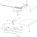
- the driving assembly 300 may include a drive source 310, a screw rod 320, a guide rod 330, a screw sleeve 340, and a support 350.
- the support 350 may provide a mounting basis for another part of the driving assembly 300.
- the drive source 310 is connected to one end of the screw rod 320, the screw rod 320 is rotatably connected to the support 350, the support 350 is connected to the guide rod 330, an extension direction of the screw rod 320 is the same as an extension direction of the guide rod 330, the screw rod 320 cooperates with the screw sleeve 340 through screwing, the screw sleeve 340 is movably sleeved on the guide rod 330, and the screw sleeve 340 is connected to the blocking member 400.
- the drive source 310 may drive the screw sleeve 340 to move by using the screw 320, to drive the blocking member 400 to move.
- the guide rod 330 guides the screw sleeve 340. Compared with a linear motor and an air cylinder, driving force provided by the driving assembly 300 is more stable, so that the blocking member 400 is less prone to slanting in a moving process.
- the drive source 310 may be a drive motor
- the support 350 may include a body part 351 and a supporting member 352, the supporting member 352 is disposed at one end of the body part 351, the drive source 310, the screw rod 320, and the guide rod 330 are mounted on the body part 351, a mounting hole is disposed on the supporting member 352, one end of the screw rod 320 is located in the mounting hole, and the screw rod 320 may rotate relative to the mounting hole.
- a first guiding part may be disposed on the housing 100, a second guiding part may be disposed on the blocking member 400, and the first guiding part cooperates with the second guiding part through sliding.
- the driving assembly 300 drives the blocking member 400 to move in an extension direction of the first guiding part, and the first guiding part may assist in limiting a movement track of the blocking member 400 by using the second guiding part, so that the blocking member 400 moves in the extension direction of the first guiding part.
- This solution can limit and guide a moving direction of the blocking member 400, to more reliably prevent the blocking member 400 from slanting in a moving process.
- the first guiding part may be a guiding groove
- the second guiding part may be a guiding protrusion.
- a third guiding part may be disposed on the functional module 200, and the third guiding part cooperates with the first guiding part through sliding.
- a movement direction of the functional module 200 can be limited and guided, to more reliably prevent the functional module 200 from slanting in a moving process.
- the first guiding part may be a guiding groove
- the third guiding part may be a guiding protrusion.
- the electronic device disclosed in this embodiment of the present invention may further include a sealing member, such as a sealing ring and a sealing strip.
- a sealing member such as a sealing ring and a sealing strip.
- the blocking member 400 and the opening 120 are sealed by using the sealing member.
- waterproof performance and dustproof performance of the electronic device are further improved.
- the housing 100 may include a bezel, and the opening 120 may be opened on the bezel.
- the bezel is located on a side surface of the housing 100, and the opening 120 is disposed on the bezel, so that the user cannot easily see the bezel, and the user has relatively weak feeling of visual impact, and therefore appearance quality of the electronic device is better.
- the electronic device disclosed in the embodiments of the present invention may be a device such as a smartphone, a tablet computer, an e-book reader, a wearable device (for example, a smart watch), or a video game.
- a specific type of the electronic device is not limited in the embodiments of the present invention.
Landscapes
- Engineering & Computer Science (AREA)
- Signal Processing (AREA)
- Human Computer Interaction (AREA)
- Casings For Electric Apparatus (AREA)
- Telephone Set Structure (AREA)
- Shielding Devices Or Components To Electric Or Magnetic Fields (AREA)
Claims (11)
- Eine elektronische Vorrichtung, umfassend:ein Gehäuse (100), wobei das Gehäuse (100) einen inneren Hohlraum (110) aufweist, und der innere Hohlraum (110) eine Öffnung (120) aufweist;dadurch gekennzeichnet, dass die elektronische Vorrichtung ferner umfasst:ein Funktionsmodul (200), wobei das Funktionsmodul (200) in der Lage ist, durch die Öffnung (120) aus dem inneren Hohlraum (110) herauszuragen, und von dem Gehäuse (100) getrennt ist, um das Funktionsmodul (200) in die Lage zu versetzen, unabhängig als ein Funktionsmonomer zu arbeiten, oder das Funktionsmodul (200) in der Lage ist, durch die Öffnung (120) in den inneren Hohlraum (110) zurückgezogen zu werdenein Sperrelement (400), wobei das Sperrelement (400) beweglich in dem inneren Hohlraum (110) angeordnet ist und das Sperrelement (400) der Öffnung (120) entspricht; undeine Antriebsbaugruppe (300), wobei die Antriebsbaugruppe (300) in dem inneren Hohlraum (110) angeordnet ist, die Antriebsbaugruppe (300) mit dem Sperrelement (400) verbunden ist, die Antriebsbaugruppe (300) das Sperrelement (400) antreibt, um zwischen einem ersten Zustand und einem zweiten Zustand umzuschalten, das Sperrelement (400) in dem ersten Zustand von der Öffnung (120) entfernt ist und das Sperrelement (400) die Öffnung (120) in dem zweiten Zustand blockiert; wobeiin einem Fall, in dem zumindest ein Teil des Funktionsmoduls (200) im inneren Hohlraum (110) angeordnet ist, das Sperrelement (400) im ersten Zustand ist, und in einem Fall, in dem das Funktionsmodul (200) von dem Gehäuse (100) getrennt ist, das Sperrelement (400) im zweiten Zustand ist.
- Elektronische Vorrichtung nach Anspruch 1, wobei in einem Fall, in dem sich das Sperrelement (400) im zweiten Zustand befindet, zumindest ein Teil des Sperrelements (400) in der Öffnung (120) angeordnet ist und ein Rand des Sperrelements (400) durch Begrenzung mit einem Rand der Öffnung (120) in einer Richtung zusammenwirkt, in der das Funktionsmodul (200) vorsteht.
- Elektronische Vorrichtung nach Anspruch 1, wobei in einem Fall, in dem sich das Sperrelement (400) im zweiten Zustand befindet, eine Außenfläche des Sperrelements (400), die dem Gehäuse (100) zugewendet ist, ebenflächig mit einer Außenfläche des Gehäuses (100) ist.
- Elektronische Vorrichtung nach Anspruch 1, wobei in einem Fall, in dem sich das Sperrelement (400) im ersten Zustand befindet, das Sperrelement (400) auf einer von der Öffnung (120) entfernten Seite des Funktionsmoduls (200) angeordnet ist, das Sperrelement (400) mit dem Funktionsmodul (200) verbunden ist, die Antriebsbaugruppe (300) das Sperrelement (400) in Bewegung setzt und das Funktionsmodul (200) aus dem inneren Hohlraum (110) herausragt oder zusammen mit dem Sperrelement (400) durch die Öffnung (120) in den inneren Hohlraum (110) eingezogen wird.
- Elektronische Vorrichtung nach Anspruch 4, wobei die elektronische Vorrichtung ferner ein Erfassungselement und ein Steuerelement umfasst, wobei das Erfassungselement so konfiguriert ist, dass es Positionsinformationen des Funktionsmoduls (200) und des Sperrelements (400) erfasst, und das Steuerelement die Antriebsbaugruppe (300) basierend auf den Positionsinformationen steuert.
- Elektronische Vorrichtung nach Anspruch 5, wobei das Erfassungselement einen ersten elektrischen Kontakt und einen zweiten elektrischen Kontakt umfasst, der erste elektrische Kontakt auf dem Sperrelement (400) angeordnet ist, der zweite elektrische Kontakt auf dem Funktionsmodul (200) angeordnet ist, und in einem Fall, in dem das Funktionsmodul (200) mit dem Sperrelement (400) verbunden ist, der erste elektrische Kontakt und der zweite elektrische Kontakt elektrisch leitend sind.
- Elektronische Vorrichtung nach Anspruch 1, wobei in einem Fall, in dem das Funktionsmodul (200) eine erste Oberfläche hat, die dem Gehäuse (100) zugewandt ist, und das Sperrelement (400) im ersten Zustand ist, die erste Oberfläche Sperrelements mit einer Oberfläche des Gehäuses (100) ist.
- Elektronische Vorrichtung nach Anspruch 1, wobei die Antriebsbaugruppe (300) eine Antriebsquelle (310), eine Schraubenstange (320), eine Führungsstange (330), eine Schraubenhülse (340) und einen Träger (350) umfasst, wobei die Antriebsquelle (310) mit einem Ende der Schraubenstange (320) verbunden ist, wobei die Schraubenstange (320) drehbar mit dem Träger (350) verbunden ist, der Träger (350) mit der Führungsstange (330) verbunden ist, eine Ausdehnungsrichtung der Schraubenstange (320) die gleiche ist wie eine Ausdehnungsrichtung der Führungsstange (330), die Schraubenstange (320) mit der Schraubenhülse (340) durch Verschrauben zusammenwirkt, die Schraubenhülse (340) beweglich auf die Führungsstange (330) aufgeschoben ist, und die Schraubenhülse (340) mit dem Sperrelement (400) verbunden ist.
- Elektronische Vorrichtung nach Anspruch 1, wobei ein erster Führungsteil im Gehäuse (100) angeordnet ist, ein zweiter Führungsteil im Sperrelement (400) angeordnet ist und der erste Führungsteil mit dem zweiten Führungsteil durch Gleiten zusammenwirkt.
- Elektronische Vorrichtung nach Anspruch 1, wobei die elektronische Vorrichtung ferner ein Dichtungselement umfasst, und in einem Fall, in dem sich das Sperrelement (400) im zweiten Zustand befindet, das Sperrelement (400) mit der Öffnung (120) durch Abdichtung unter Verwendung des Dichtungselements zusammenwirkt.
- Elektronische Vorrichtung nach einem der Ansprüche 1 bis 10, wobei das Funktionsmodul (200) mindestens eines von einem Kameramodul, einem Fingerabdruckerkennungsmodul, einem Empfänger, einem Stroboskoplicht, einem Sensor, einem unbemannten Luftfahrzeug oder einem Kartenhalter umfasst.
Applications Claiming Priority (2)
| Application Number | Priority Date | Filing Date | Title |
|---|---|---|---|
| CN202010222978.8A CN111416896B (zh) | 2020-03-26 | 2020-03-26 | 电子设备 |
| PCT/CN2021/075178 WO2021190172A1 (zh) | 2020-03-26 | 2021-02-04 | 电子设备 |
Publications (3)
| Publication Number | Publication Date |
|---|---|
| EP4131897A1 EP4131897A1 (de) | 2023-02-08 |
| EP4131897A4 EP4131897A4 (de) | 2023-09-06 |
| EP4131897B1 true EP4131897B1 (de) | 2025-06-04 |
Family
ID=71494694
Family Applications (1)
| Application Number | Title | Priority Date | Filing Date |
|---|---|---|---|
| EP21776839.9A Active EP4131897B1 (de) | 2020-03-26 | 2021-02-04 | Elektronische vorrichtung |
Country Status (6)
| Country | Link |
|---|---|
| US (1) | US12375594B2 (de) |
| EP (1) | EP4131897B1 (de) |
| KR (1) | KR102697332B1 (de) |
| CN (1) | CN111416896B (de) |
| ES (1) | ES3035614T3 (de) |
| WO (1) | WO2021190172A1 (de) |
Families Citing this family (4)
| Publication number | Priority date | Publication date | Assignee | Title |
|---|---|---|---|---|
| CN111416896B (zh) | 2020-03-26 | 2022-04-12 | 维沃移动通信有限公司 | 电子设备 |
| CN112040039B (zh) * | 2020-09-24 | 2022-05-17 | 维沃移动通信有限公司 | 电子设备 |
| CN112118338A (zh) * | 2020-09-29 | 2020-12-22 | 维沃移动通信有限公司 | 电子设备 |
| CN113099001A (zh) * | 2021-03-31 | 2021-07-09 | 维沃移动通信有限公司 | 电子设备 |
Family Cites Families (29)
| Publication number | Priority date | Publication date | Assignee | Title |
|---|---|---|---|---|
| JP3979208B2 (ja) * | 2002-07-22 | 2007-09-19 | ソニー株式会社 | 記録及び/又は再生装置 |
| CN200976410Y (zh) * | 2006-11-17 | 2007-11-14 | 达昌电子科技(苏州)有限公司 | 具防尘盖的电子卡连接器 |
| CN101351096B (zh) * | 2007-07-20 | 2011-08-24 | 鸿富锦精密工业(深圳)有限公司 | 存储卡防尘装置 |
| CN201146552Y (zh) * | 2007-12-21 | 2008-11-05 | 比亚迪股份有限公司 | 一种具有可拆卸摄像头的手机 |
| CN202095214U (zh) * | 2011-06-10 | 2011-12-28 | 新疆天地集团有限公司 | 内置伸缩耳机的终端设备 |
| KR101929879B1 (ko) * | 2012-04-09 | 2019-03-15 | 삼성전자주식회사 | 휴대 단말기 |
| CN104064908A (zh) * | 2013-03-19 | 2014-09-24 | 泰科电子(上海)有限公司 | 电子卡连接器和包括该电子卡连接器的电子设备 |
| CN203722944U (zh) * | 2013-12-18 | 2014-07-16 | 上海岱诺信息技术有限公司 | 支持嵌入式模块内嵌安装的电子设备机构 |
| KR102207162B1 (ko) * | 2014-06-11 | 2021-01-25 | 삼성전자주식회사 | 카메라 장치 및 카메라 장치를 구비한 전자 장치 |
| CN105554196A (zh) * | 2016-01-26 | 2016-05-04 | 孔岳 | 一种全屏手机 |
| CN206413039U (zh) * | 2016-11-25 | 2017-08-15 | 维沃移动通信有限公司 | 可机械锁定sim卡托的移动终端 |
| CN206413044U (zh) * | 2016-12-25 | 2017-08-15 | 北京沃凡思智选家居科技有限公司 | 带有摄像单元的手机 |
| CN107071103A (zh) * | 2017-03-28 | 2017-08-18 | 北京小米移动软件有限公司 | 移动终端 |
| CN107197133B (zh) * | 2017-07-21 | 2019-11-29 | 维沃移动通信有限公司 | 一种移动终端及摄像头组件 |
| CN207442927U (zh) * | 2017-10-31 | 2018-06-01 | 厦门城联科技有限公司 | 一种可自动弹出蓝牙的手机 |
| CN107800828A (zh) * | 2017-11-16 | 2018-03-13 | 珠海市魅族科技有限公司 | 终端设备及其控制方法与计算机可读存储介质及装置 |
| CN113099083B (zh) * | 2017-11-30 | 2023-04-18 | Oppo广东移动通信有限公司 | 摄像头组件、移动终端及其摄像头组件的控制方法 |
| CN207560151U (zh) * | 2017-12-18 | 2018-06-29 | Tcl通力电子(惠州)有限公司 | 摄像头组件及电子设备 |
| CN108200244A (zh) * | 2017-12-28 | 2018-06-22 | 广东欧珀移动通信有限公司 | 电子装置 |
| CN108337336B (zh) * | 2018-01-23 | 2021-03-12 | Oppo广东移动通信有限公司 | 电子组件和电子设备 |
| CN110460697B (zh) * | 2018-05-07 | 2021-07-13 | Oppo广东移动通信有限公司 | 电子设备 |
| CN110460694B (zh) * | 2018-05-07 | 2021-07-13 | Oppo广东移动通信有限公司 | 电子设备 |
| CN110557470B (zh) * | 2018-05-31 | 2024-07-26 | Oppo广东移动通信有限公司 | 移动终端 |
| CN108924310B (zh) * | 2018-07-25 | 2021-01-08 | 维沃移动通信有限公司 | 一种移动终端 |
| CN209517206U (zh) * | 2018-10-31 | 2019-10-18 | Oppo广东移动通信有限公司 | 移动终端和图像采集设备 |
| CN110049222B (zh) * | 2019-04-30 | 2021-12-03 | 维沃移动通信(杭州)有限公司 | 移动终端 |
| CN110198372B (zh) * | 2019-05-31 | 2020-10-09 | 华为技术有限公司 | 确定摄像组件伸缩状态的方法、可读存储介质及相关设备 |
| CN111405155A (zh) * | 2020-03-20 | 2020-07-10 | 维沃移动通信有限公司 | 电子设备和可独立摄像模组 |
| CN111416896B (zh) * | 2020-03-26 | 2022-04-12 | 维沃移动通信有限公司 | 电子设备 |
-
2020
- 2020-03-26 CN CN202010222978.8A patent/CN111416896B/zh active Active
-
2021
- 2021-02-04 ES ES21776839T patent/ES3035614T3/es active Active
- 2021-02-04 EP EP21776839.9A patent/EP4131897B1/de active Active
- 2021-02-04 WO PCT/CN2021/075178 patent/WO2021190172A1/zh not_active Ceased
- 2021-02-04 KR KR1020227035544A patent/KR102697332B1/ko active Active
-
2022
- 2022-09-22 US US17/951,073 patent/US12375594B2/en active Active
Also Published As
| Publication number | Publication date |
|---|---|
| KR102697332B1 (ko) | 2024-08-23 |
| EP4131897A1 (de) | 2023-02-08 |
| WO2021190172A1 (zh) | 2021-09-30 |
| ES3035614T3 (en) | 2025-09-05 |
| CN111416896A (zh) | 2020-07-14 |
| US20230015804A1 (en) | 2023-01-19 |
| EP4131897A4 (de) | 2023-09-06 |
| CN111416896B (zh) | 2022-04-12 |
| US12375594B2 (en) | 2025-07-29 |
| KR20220154185A (ko) | 2022-11-21 |
Similar Documents
| Publication | Publication Date | Title |
|---|---|---|
| EP4131897B1 (de) | Elektronische vorrichtung | |
| JP7089016B2 (ja) | 移動端末及びカメラアセンブリ | |
| EP4117255B1 (de) | Elektronische vorrichtung | |
| US11023019B2 (en) | Mobile terminal | |
| WO2019184978A1 (zh) | 移动终端 | |
| CN109803082B (zh) | 移动终端 | |
| US12160962B2 (en) | Electronic device | |
| CN211349017U (zh) | 可穿戴设备 | |
| CN112995469B (zh) | 拍摄装置及电子设备 | |
| CN111510525B (zh) | 电子设备 | |
| CN109831553B (zh) | 终端设备 | |
| CN210662063U (zh) | 电子设备 | |
| CN113452823A (zh) | 电子设备 | |
| CN109873886B (zh) | 终端设备 | |
| WO2023011353A1 (zh) | 摄像头模组和电子设备 | |
| EP4092999B1 (de) | Elektronisches gerät und funktionsmodul dafür | |
| CN110753175B (zh) | 一种电子设备 | |
| CN110336900A (zh) | 摄像头模组及移动终端 | |
| WO2020221352A1 (zh) | 终端设备 | |
| CN113225468B (zh) | 摄像模组及电子设备 | |
| US20240267445A1 (en) | Electronic device | |
| CN110518741B (zh) | 电子设备 | |
| CN110784631A (zh) | 电子设备 | |
| CN109962995A (zh) | 功能组件、电子装置及其控制方法 | |
| CN111510608B (zh) | 功能模组及电子设备 |
Legal Events
| Date | Code | Title | Description |
|---|---|---|---|
| STAA | Information on the status of an ep patent application or granted ep patent |
Free format text: STATUS: THE INTERNATIONAL PUBLICATION HAS BEEN MADE |
|
| PUAI | Public reference made under article 153(3) epc to a published international application that has entered the european phase |
Free format text: ORIGINAL CODE: 0009012 |
|
| STAA | Information on the status of an ep patent application or granted ep patent |
Free format text: STATUS: REQUEST FOR EXAMINATION WAS MADE |
|
| 17P | Request for examination filed |
Effective date: 20221010 |
|
| AK | Designated contracting states |
Kind code of ref document: A1 Designated state(s): AL AT BE BG CH CY CZ DE DK EE ES FI FR GB GR HR HU IE IS IT LI LT LU LV MC MK MT NL NO PL PT RO RS SE SI SK SM TR |
|
| DAV | Request for validation of the european patent (deleted) | ||
| DAX | Request for extension of the european patent (deleted) | ||
| A4 | Supplementary search report drawn up and despatched |
Effective date: 20230808 |
|
| RIC1 | Information provided on ipc code assigned before grant |
Ipc: H04M 1/18 20060101ALI20230803BHEP Ipc: H04M 1/02 20060101AFI20230803BHEP |
|
| GRAP | Despatch of communication of intention to grant a patent |
Free format text: ORIGINAL CODE: EPIDOSNIGR1 |
|
| STAA | Information on the status of an ep patent application or granted ep patent |
Free format text: STATUS: GRANT OF PATENT IS INTENDED |
|
| INTG | Intention to grant announced |
Effective date: 20250319 |
|
| GRAS | Grant fee paid |
Free format text: ORIGINAL CODE: EPIDOSNIGR3 |
|
| GRAA | (expected) grant |
Free format text: ORIGINAL CODE: 0009210 |
|
| STAA | Information on the status of an ep patent application or granted ep patent |
Free format text: STATUS: THE PATENT HAS BEEN GRANTED |
|
| AK | Designated contracting states |
Kind code of ref document: B1 Designated state(s): AL AT BE BG CH CY CZ DE DK EE ES FI FR GB GR HR HU IE IS IT LI LT LU LV MC MK MT NL NO PL PT RO RS SE SI SK SM TR |
|
| REG | Reference to a national code |
Ref country code: GB Ref legal event code: FG4D |
|
| REG | Reference to a national code |
Ref country code: CH Ref legal event code: EP |
|
| REG | Reference to a national code |
Ref country code: DE Ref legal event code: R096 Ref document number: 602021031834 Country of ref document: DE |
|
| REG | Reference to a national code |
Ref country code: IE Ref legal event code: FG4D |
|
| REG | Reference to a national code |
Ref country code: NL Ref legal event code: FP |
|
| REG | Reference to a national code |
Ref country code: ES Ref legal event code: FG2A Ref document number: 3035614 Country of ref document: ES Kind code of ref document: T3 Effective date: 20250905 |
|
| PG25 | Lapsed in a contracting state [announced via postgrant information from national office to epo] |
Ref country code: FI Free format text: LAPSE BECAUSE OF FAILURE TO SUBMIT A TRANSLATION OF THE DESCRIPTION OR TO PAY THE FEE WITHIN THE PRESCRIBED TIME-LIMIT Effective date: 20250604 |
|
| REG | Reference to a national code |
Ref country code: LT Ref legal event code: MG9D |
|
| PG25 | Lapsed in a contracting state [announced via postgrant information from national office to epo] |
Ref country code: GR Free format text: LAPSE BECAUSE OF FAILURE TO SUBMIT A TRANSLATION OF THE DESCRIPTION OR TO PAY THE FEE WITHIN THE PRESCRIBED TIME-LIMIT Effective date: 20250905 Ref country code: NO Free format text: LAPSE BECAUSE OF FAILURE TO SUBMIT A TRANSLATION OF THE DESCRIPTION OR TO PAY THE FEE WITHIN THE PRESCRIBED TIME-LIMIT Effective date: 20250904 |
|
| PG25 | Lapsed in a contracting state [announced via postgrant information from national office to epo] |
Ref country code: PL Free format text: LAPSE BECAUSE OF FAILURE TO SUBMIT A TRANSLATION OF THE DESCRIPTION OR TO PAY THE FEE WITHIN THE PRESCRIBED TIME-LIMIT Effective date: 20250604 |
|
| PG25 | Lapsed in a contracting state [announced via postgrant information from national office to epo] |
Ref country code: BG Free format text: LAPSE BECAUSE OF FAILURE TO SUBMIT A TRANSLATION OF THE DESCRIPTION OR TO PAY THE FEE WITHIN THE PRESCRIBED TIME-LIMIT Effective date: 20250604 |
|
| PG25 | Lapsed in a contracting state [announced via postgrant information from national office to epo] |
Ref country code: HR Free format text: LAPSE BECAUSE OF FAILURE TO SUBMIT A TRANSLATION OF THE DESCRIPTION OR TO PAY THE FEE WITHIN THE PRESCRIBED TIME-LIMIT Effective date: 20250604 |
|
| PG25 | Lapsed in a contracting state [announced via postgrant information from national office to epo] |
Ref country code: RS Free format text: LAPSE BECAUSE OF FAILURE TO SUBMIT A TRANSLATION OF THE DESCRIPTION OR TO PAY THE FEE WITHIN THE PRESCRIBED TIME-LIMIT Effective date: 20250904 |
|
| PG25 | Lapsed in a contracting state [announced via postgrant information from national office to epo] |
Ref country code: LV Free format text: LAPSE BECAUSE OF FAILURE TO SUBMIT A TRANSLATION OF THE DESCRIPTION OR TO PAY THE FEE WITHIN THE PRESCRIBED TIME-LIMIT Effective date: 20250604 |
|
| PG25 | Lapsed in a contracting state [announced via postgrant information from national office to epo] |
Ref country code: PT Free format text: LAPSE BECAUSE OF FAILURE TO SUBMIT A TRANSLATION OF THE DESCRIPTION OR TO PAY THE FEE WITHIN THE PRESCRIBED TIME-LIMIT Effective date: 20251006 |
|
| REG | Reference to a national code |
Ref country code: AT Ref legal event code: MK05 Ref document number: 1801470 Country of ref document: AT Kind code of ref document: T Effective date: 20250604 |
|
| PG25 | Lapsed in a contracting state [announced via postgrant information from national office to epo] |
Ref country code: IS Free format text: LAPSE BECAUSE OF FAILURE TO SUBMIT A TRANSLATION OF THE DESCRIPTION OR TO PAY THE FEE WITHIN THE PRESCRIBED TIME-LIMIT Effective date: 20251004 |
|
| PG25 | Lapsed in a contracting state [announced via postgrant information from national office to epo] |
Ref country code: SM Free format text: LAPSE BECAUSE OF FAILURE TO SUBMIT A TRANSLATION OF THE DESCRIPTION OR TO PAY THE FEE WITHIN THE PRESCRIBED TIME-LIMIT Effective date: 20250604 Ref country code: AT Free format text: LAPSE BECAUSE OF FAILURE TO SUBMIT A TRANSLATION OF THE DESCRIPTION OR TO PAY THE FEE WITHIN THE PRESCRIBED TIME-LIMIT Effective date: 20250604 |
|
| PGFP | Annual fee paid to national office [announced via postgrant information from national office to epo] |
Ref country code: FR Payment date: 20251231 Year of fee payment: 6 |
|
| PG25 | Lapsed in a contracting state [announced via postgrant information from national office to epo] |
Ref country code: CZ Free format text: LAPSE BECAUSE OF FAILURE TO SUBMIT A TRANSLATION OF THE DESCRIPTION OR TO PAY THE FEE WITHIN THE PRESCRIBED TIME-LIMIT Effective date: 20250604 |
|
| PG25 | Lapsed in a contracting state [announced via postgrant information from national office to epo] |
Ref country code: EE Free format text: LAPSE BECAUSE OF FAILURE TO SUBMIT A TRANSLATION OF THE DESCRIPTION OR TO PAY THE FEE WITHIN THE PRESCRIBED TIME-LIMIT Effective date: 20250604 |
|
| PG25 | Lapsed in a contracting state [announced via postgrant information from national office to epo] |
Ref country code: SK Free format text: LAPSE BECAUSE OF FAILURE TO SUBMIT A TRANSLATION OF THE DESCRIPTION OR TO PAY THE FEE WITHIN THE PRESCRIBED TIME-LIMIT Effective date: 20250604 |
|
| PGFP | Annual fee paid to national office [announced via postgrant information from national office to epo] |
Ref country code: NL Payment date: 20260106 Year of fee payment: 6 |