EP4117255B1 - Elektronische vorrichtung - Google Patents
Elektronische vorrichtung Download PDFInfo
- Publication number
- EP4117255B1 EP4117255B1 EP21763970.7A EP21763970A EP4117255B1 EP 4117255 B1 EP4117255 B1 EP 4117255B1 EP 21763970 A EP21763970 A EP 21763970A EP 4117255 B1 EP4117255 B1 EP 4117255B1
- Authority
- EP
- European Patent Office
- Prior art keywords
- slider
- functional module
- accommodating space
- electronic device
- connecting rod
- Prior art date
- Legal status (The legal status is an assumption and is not a legal conclusion. Google has not performed a legal analysis and makes no representation as to the accuracy of the status listed.)
- Active
Links
Images


Classifications
-
- H—ELECTRICITY
- H04—ELECTRIC COMMUNICATION TECHNIQUE
- H04M—TELEPHONIC COMMUNICATION
- H04M1/00—Substation equipment, e.g. for use by subscribers
- H04M1/02—Constructional features of telephone sets
- H04M1/0202—Portable telephone sets, e.g. cordless phones, mobile phones or bar type handsets
- H04M1/026—Details of the structure or mounting of specific components
- H04M1/0264—Details of the structure or mounting of specific components for a camera module assembly
-
- H—ELECTRICITY
- H05—ELECTRIC TECHNIQUES NOT OTHERWISE PROVIDED FOR
- H05K—PRINTED CIRCUITS; CASINGS OR CONSTRUCTIONAL DETAILS OF ELECTRIC APPARATUS; MANUFACTURE OF ASSEMBLAGES OF ELECTRICAL COMPONENTS
- H05K7/00—Constructional details common to different types of electric apparatus
- H05K7/14—Mounting supporting structure in casing or on frame or rack
- H05K7/1401—Mounting supporting structure in casing or on frame or rack comprising clamping or extracting means
-
- G—PHYSICS
- G06—COMPUTING OR CALCULATING; COUNTING
- G06F—ELECTRIC DIGITAL DATA PROCESSING
- G06F1/00—Details not covered by groups G06F3/00 - G06F13/00 and G06F21/00
- G06F1/16—Constructional details or arrangements
- G06F1/1613—Constructional details or arrangements for portable computers
- G06F1/1615—Constructional details or arrangements for portable computers with several enclosures having relative motions, each enclosure supporting at least one I/O or computing function
- G06F1/1624—Constructional details or arrangements for portable computers with several enclosures having relative motions, each enclosure supporting at least one I/O or computing function with sliding enclosures, e.g. sliding keyboard or display
-
- G—PHYSICS
- G06—COMPUTING OR CALCULATING; COUNTING
- G06F—ELECTRIC DIGITAL DATA PROCESSING
- G06F1/00—Details not covered by groups G06F3/00 - G06F13/00 and G06F21/00
- G06F1/16—Constructional details or arrangements
- G06F1/1613—Constructional details or arrangements for portable computers
- G06F1/1626—Constructional details or arrangements for portable computers with a single-body enclosure integrating a flat display, e.g. Personal Digital Assistants [PDAs]
-
- G—PHYSICS
- G06—COMPUTING OR CALCULATING; COUNTING
- G06F—ELECTRIC DIGITAL DATA PROCESSING
- G06F1/00—Details not covered by groups G06F3/00 - G06F13/00 and G06F21/00
- G06F1/16—Constructional details or arrangements
- G06F1/1613—Constructional details or arrangements for portable computers
- G06F1/1633—Constructional details or arrangements of portable computers not specific to the type of enclosures covered by groups G06F1/1615 - G06F1/1626
- G06F1/1684—Constructional details or arrangements related to integrated I/O peripherals not covered by groups G06F1/1635 - G06F1/1675
- G06F1/1686—Constructional details or arrangements related to integrated I/O peripherals not covered by groups G06F1/1635 - G06F1/1675 the I/O peripheral being an integrated camera
-
- H—ELECTRICITY
- H04—ELECTRIC COMMUNICATION TECHNIQUE
- H04M—TELEPHONIC COMMUNICATION
- H04M1/00—Substation equipment, e.g. for use by subscribers
- H04M1/02—Constructional features of telephone sets
- H04M1/0202—Portable telephone sets, e.g. cordless phones, mobile phones or bar type handsets
- H04M1/0254—Portable telephone sets, e.g. cordless phones, mobile phones or bar type handsets comprising one or a plurality of mechanically detachable modules
- H04M1/0256—Portable telephone sets, e.g. cordless phones, mobile phones or bar type handsets comprising one or a plurality of mechanically detachable modules wherein the modules are operable in the detached state, e.g. one module for the user interface and one module for the transceiver
-
- H—ELECTRICITY
- H04—ELECTRIC COMMUNICATION TECHNIQUE
- H04M—TELEPHONIC COMMUNICATION
- H04M1/00—Substation equipment, e.g. for use by subscribers
- H04M1/02—Constructional features of telephone sets
- H04M1/0202—Portable telephone sets, e.g. cordless phones, mobile phones or bar type handsets
- H04M1/026—Details of the structure or mounting of specific components
-
- H—ELECTRICITY
- H04—ELECTRIC COMMUNICATION TECHNIQUE
- H04N—PICTORIAL COMMUNICATION, e.g. TELEVISION
- H04N23/00—Cameras or camera modules comprising electronic image sensors; Control thereof
- H04N23/57—Mechanical or electrical details of cameras or camera modules specially adapted for being embedded in other devices
-
- H—ELECTRICITY
- H04—ELECTRIC COMMUNICATION TECHNIQUE
- H04M—TELEPHONIC COMMUNICATION
- H04M1/00—Substation equipment, e.g. for use by subscribers
- H04M1/02—Constructional features of telephone sets
- H04M1/0202—Portable telephone sets, e.g. cordless phones, mobile phones or bar type handsets
- H04M1/0206—Portable telephones comprising a plurality of mechanically joined movable body parts, e.g. hinged housings
- H04M1/0208—Portable telephones comprising a plurality of mechanically joined movable body parts, e.g. hinged housings characterized by the relative motions of the body parts
- H04M1/0235—Slidable or telescopic telephones, i.e. with a relative translation movement of the body parts; Telephones using a combination of translation and other relative motions of the body parts
- H04M1/0237—Sliding mechanism with one degree of freedom
Definitions
- the present invention relates to the field of communication device technologies, and in particular, to an electronic device.
- a relatively large screen-to-body ratio causes the electronic devices to have some functional modules embedded inside the electronic devices.
- the functional module may be driven by a driving mechanism to extend out of the shell of the electronic devices to work.
- the functional module with such a structure does not occupy the panel surface space of the electronic devices, so as to enable an increase of the screen-to-body ratio.
- the functional modules of the existing electronic devices can only work at extended positions and have the problem of poor flexibility in use.
- WO2019228324A1 discloses a mobile terminal, including a host and an image collection device.
- the host includes an outer shell, a display screen and an ejection mechanism, the outer shell including a rear wall and a side wall which enclose a receiving space, the display screen covering the receiving space, the ejection mechanism being arranged inside the receiving space, and a mounting hole being provided on the side wall; and the image collection device includes a camera module and a first connection end, which are connected to each other, the camera module having a light incident face, where the image collection device can be received inside the mounting hole and can be ejected by means of the ejection mechanism so as to be detached; after being detached, the image collection device can be connected to the host by means of the first connection end, so that the light incident face is exposed at one side of the display screen and the image collection device can have a communication connection with the host.
- CN110519418A discloses a functional assembly.
- the functional assembly includes a first support and a functional module.
- the first bracket includes a base and a sliding seat, and the sliding seat can slide relative to the base; the functional module is detachably connected with the sliding seat and synchronously slides with the sliding seat, the functional module can slide to a separation position, and the functional module can be separated from the sliding seat under the action of external force when the functional module is located at the separation position.
- CN209748616U discloses a separated rear-mounted camera of a mobile phone. Included are a main body and a camera module, the middle of the main body is fixedly connected with a shell; the photographing module is located on the inner side of the top end of the shell.
- a first magnet is fixedly connected to the middle of the bottom end of the photographing module; a second magnet is fixedly connected to the inner side, corresponding to the shell, of the bottom end of the photographing module, a sliding metal rod is fixedly connected to the position, corresponding to the photographing module, of the middle of the two sides of the second magnet, and fixing springs are fixedly connected to the bottom ends of the two sides of the second magnet corresponding to the shell.
- CN109218480A discloses a terminal equipment.
- the frame of a shell is provided with perforations.
- a camera is movably disposed on the housing, and has a retraction stroke and an ejection stroke relative to the housing.
- the driving mechanism includes a first elastic part and an elastic hook, where the camera head is provided with a guide rail, the guide rail is provided with an articulation part, the first end of the elastic hook is connected with the housing, the second end is slidably matched with the guide rail, the elastic hook can exert a pulling force on the camera head, and the first elastic part can exert an elastic force on the camera head, and the elastic force is opposite to the pulling force direction.
- the pulling force is greater than the elastic force
- the second end of the elastic hook slides into the articulation part and is articulated with the articulation part
- the camera moves into the housing.
- the elastic force is greater than the tensile force
- the second end of the elastic hook slides out of the hitch, and the camera moves out of the housing through the perforation.
- Embodiments of the present invention disclose an electronic device, to resolve the problem of a functional module in an existing electronic device has poor flexibility in use.
- the functional module is detachably connected to the slider.
- the functional module can extend out of the first accommodating space or retract into the first accommodating space through the slider.
- the functional module and the slider can be in a separated state, so that the functional module not only can work outside the first accommodating space, but also can work separately from the device body.
- the user only needs to press the functional module to implement installation and removal of the functional module, thereby facilitating driving of the functional module and further improving the flexibility of the functional module.
- an electronic device is disclosed in this embodiment of the present invention.
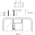
- the disclosed electronic device includes a device body 100, a functional module 200, and an ejection mechanism.
- the device body 100 is provided with a first accommodating space 110, a second accommodating space 120, and a first opening 130 in communication with the first accommodating space 110.
- the second accommodating space 120 is in communication with the first accommodating space 110.
- the second accommodating space 120 has a second opening.
- the first accommodating space 110 is in communication with the second accommodating space 120 through the second opening.
- the first accommodating space 110 can provide a mounting position for the functional module 200.
- the functional module 200 can retract into the first accommodating space 110 through the first opening 130. Alternatively, at least a part of the functional module 200 can extend out of the first accommodating space 110 through the first opening 130.
- the second accommodating space 120 can provide a mounting position for the ejection mechanism.
- the first opening 130 may be provided on a second shell 150 of the device body 100.
- the first opening 130 may be provided on a middle frame of the second shell 150.
- the first opening 130 may also be provided at another position of the second shell 150.
- a specific position of the first opening 130 is not limited in the embodiments of the present
- the functional module 200 may include at least one of a camera, a light filling module, a fingerprint identification module, a microphone, an electrical connection port, a data card, and a phone receiver. Certainly, the functional module 200 may also be another type of functional device. A specific type of the functional module 200 is not limited in the embodiments of the present invention.
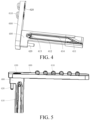
- the ejection mechanism includes a connecting rod 300, a slider 400, and a driving part 500.
- the functional module 200 is detachably connected to the slider 400.
- a guide rail 410 is disposed on the slider 400.
- the guide rail 410 includes a first limiting section 411, an extending section 412, a second limiting section 413, and a retracting section 414 connected in sequence. Both the extending section 412 and the retracting section 414 implement the function of connecting the first limiting section 411 and the second limiting section 413.
- first limiting section 411 is connected to an opposite end of the second limiting section 413 by the extending section 412, and the other end of the first limiting section 411 is connected to an opposite end of the second limiting section 413 by the retracting section 414.
- the driving part 500 is disposed inside the second accommodating space 120, and the driving part 500 can drive the slider 400 to move along a direction perpendicular to the first opening 130.
- the driving part 500 can drive the slider 400 to move and make at least a part of the slider 400 extend out of the second accommodating space 120 through the second opening, so as to push the functional module 200 to move and make at least a part of the functional module 200 extend out of the first accommodating space 110 through the first opening 130.
- the driving part 500 may be a spiral telescopic spring or an elastic rubber element.
- a specific type of the driving part 500 is not limited in the embodiments of the present invention.
- a first end of the connecting rod 300 is hinged to an inner wall of the second accommodating space 120, and a second end of the connecting rod 300 is slidably matched with the guide rail 410, so that the second end of the connecting rod 300 slides to respective parts of the guide rail 410 during the movement of the slider 400.
- the first end of the connecting rod 300 is rotated, to enable the second end of the connecting rod 300 to adaptively is slidably matched with the first limiting section 411, the extending section 412, the second limiting section 413, and the retracting section 414.
- Both the matching between the second end of the connecting rod 300 and the first limiting section 411, and the matching between the second end of the connecting rod 300 and the second limiting section 413 can maintain the slider 400 at a specified position.
- the functional module 200 in a case that the slider 400 is connected to the functional module 200, the functional module 200 can be maintained by the slider 400 at an extending position and a retracting position that are described above.
- the first limiting section 411 may include a first sub-limiting section and a second sub-limiting section.
- the first sub-limiting section and the second sub-limiting section are disposed spaced apart.
- the second limiting section 413 may be a broken-line limiting section.
- One end of the first sub-limiting section is connected to a first end of the broken-line limiting section by the extending section 412, and one end of the second sub-limiting section is connected to a second end of the broken-line limiting section by the retracting section 414.
- the extending section 412 and the retracting section 414 may be disposed opposite to each other and inclinedly.
- a distance between one end of the extending section 412 close to the first sub-limiting section and one end of the retracting section 414 close to the second sub-limiting section is a first distance
- a distance between one end of the extending section 412 close to the broken-line limiting section and one end of the retracting section 414 close to the broken-line limiting section is a second distance, where the first distance is smaller than the second distance, so that a part of the guide rail 410 may be in an "M"-shaped structure.
- the extending section 412 and the retracting section 414 are disposed inclinedly, to guide the second end of the connecting rod 300 better, so that the second end of the connecting rod 300 has smaller resistance when moving between the first limiting section 411 and the second limiting section 413, and slides more steadily, thereby preventing the second end of the connecting rod 300 from being suck during movement.
- the guide rail 410 may be an annual rail. Specifically, a first end of the first limiting section 411 is connected to the extending section 412, and a second end of the first limiting section 411 is connected to the retracting section 414. A first end of the second limiting section 413 is connected to the extending section 412, and a second end of the second limiting section 413 is connected to the retracting section 414.
- the second end of the connecting rod 300 can slide relative to the guide rail 410. Referring to FIG.
- the second end of the connecting rod 300 can enter the retracting section 414 from the first limiting section 411, enter the second limiting section 413 from the retracting section 414, enter the extending section 412 from the second limiting section 413, and enter the first limiting section 411 from the extending section 412, and repeat the process in sequence as being pressed.
- the extending section 412 and the retracting section 414 implement a guiding function, to cause the second end of the connecting rod 300 to switch between matching the first limiting section 411 and matching the second limiting section 413, so that the movement of the second end of the connecting rod 300 is smoother.
- the functional module 200 has a first state and a second state. In a case that the functional module 200 is in the first state, the functional module 200 is separated from the slider 400. In this case, the functional module 200 may be separated from the device body 100, so that the functional module 200 can work away from the device body 100.
- the functional module 200 is connected to the slider 400, and the slider 400 is movable between a first position and a second position.
- the slider 400 when the slider 400 is at the first position, the slider 400 is located inside the second accommodating space 120, and the second end of the connecting rod 300 is matched with the second limiting section 412 to restrict the slider 400 from moving toward the first opening 130.
- the matching between the second end of the connecting rod 300 and the second limiting section 412 can maintain the slider 400 at the first position.
- the slider 400 is at the second position, at least a part of the slider 400 is located outside the second accommodating space 120, and the second end of the connecting rod 300 is matched with the first limiting section 411 to restrict the slider 400 from moving toward the first opening 130.
- the matching between the second end of the connecting rod 300 and the first limiting section 411 can maintain the slider 400 at the second position.
- An acting force generated by the second end of the connecting rod 300 on the slider 400 is opposite to an acting force generated by the driving part 500 on the slider 400, so that the slider 400 can be maintained at a corresponding position.
- the functional module 200 is connected to the slider 400, in a case that the slider 400 is at the second position, at least a part of the functional module 200 is located outside the first accommodating space 110. In a case that the slider 400 is at the first position, the functional module 200 is located inside the first accommodating space 110. Therefore, the functional module 200 can be maintained at a corresponding position by maintaining the slider 400 at a corresponding position.
- the user may manually press the functional module 200. Further, the functional module 200 enables the slider 400 to overcome the acting force of the driving part 500.
- the second end of the connecting rod 300 can slide from the first limiting section 411 through the retracting section 414 to a position at which the second end of the connecting rod 300 is matched with the second limiting section 413.
- the slider 400 is located at the first position to make the functional module 200 be located inside the first accommodating space 110. Under the action of the acting force of the driving part 500 and the matching of the second limiting section 413, the functional module 200 can be maintained at the position inside the first accommodating space 110.
- the user may press the functional module 200 again, to enable the slider 400 to overcome the acting force of the driving part 500.
- the second end of the connecting rod 300 may slide from the second limiting section 413 through the extending section 412 to a position at which the second end of the connecting rod 300 is matched with the first limiting section 411.
- the slider 400 drives the functional module 200 to make at least a part of the functional module 200 extend out of the first accommodating space 110 through the first opening 130.
- the slider 400 Under the action of the acting force of the driving part 500 and the matching of the second limiting section 413, the slider 400 can be maintained at the first position.
- at least a part of the functional module 200 may be maintained at a position inside the first accommodating space 110, and the functional module 200 may also be separated from the slider 400, so that the functional module 200 can work away from the device body 100.
- the functional module 200 is detachably connected to the slider 400.
- the functional module 200 can extend out of the first accommodating space 110 or retract into the first accommodating space 110 through the slider 400.
- the functional module 200 and the slider 400 can be in a separated state, so that the functional module 200 not only can work outside the first accommodating space 110, but also can work separately from the device body 100.
- the user only needs to press the functional module 200 to implement installation and removal of the functional module 200, thereby facilitating driving of the functional module 200 and further improving the flexibility of the functional module 200.
- the above ejection mechanism is a manual driving mechanism, which enables the functional module 200 to enter and exit the first accommodating space 110 without power consumption, so that the power consumption of the entire electronic device can be reduced.
- both the functional module 200 and the ejection mechanism have an independent installation space, so that the ejection mechanism drives the functional module 200 relatively steadily.
- the ejection mechanism may further include a connecting base 600.
- the connecting base 600 may be connected to the slider 400, and the slider 400 is detachably connected to the functional module 200 by the connecting base 600.
- the slider 400 may drive, through the connecting base 600, the functional module 200 to move. It should be noted that in a telescopic direction of the functional module 200, the projection area of the connecting base 600 is larger than the projection area of the slider 400.
- the contact area between the connecting base 600 and the functional module 200 is larger, so that the driving forces of the connecting base 600 on positions of the functional module 200 are evener, thereby enabling the slider 400 to drive the functional module 200 more steadily.
- the connecting base 600 may be hermetically connected to the first opening 130.
- the connecting base 600 may block the first opening 130, so that the first accommodating space 110 and the second accommodating space 120 form a sealed space, thereby implementing a water-proof and dust-proof function.
- a seal ring may be disposed between the connecting base 600 and the first opening 130, the connecting base 600 may be hermetically connected to the first opening 130 by the seal ring.
- the connecting base 600 may also be hermetically connected to the first opening 130 in various manners. A specific manner in which the connecting base 600 is hermetically connected to the first opening 130 is not limited in the embodiments of the present invention.
- an outer surface of the connecting base 600 is flush with an outer surface at which the first opening 130 is located.
- the connecting base 600 blocks the first opening 130, and an outer surface of the connecting base 600 is flush with the outer surface at which the first opening 130 is located, which not only implements the water-proof and dust-proof function, but also makes the appearance of the electronic device better.
- a first electrical interface 210 may be disposed on the functional module 200
- a second electrical interface 610 may be disposed on one side of the connecting base 600 facing away from the slider 400
- a third electrical interface 620 may be disposed on one side of the connecting base 600 facing the slider 400.
- the second electrical interface 610 is electrically connected to the third electrical interface 620.
- a fourth electrical interface 111 may be disposed in the first accommodating space 110.
- the first electrical interface 210 may be electrically connected to the second electrical interface 610
- the third electrical interface 620 may be electrically connected to the fourth electrical interface 111.
- the functional module 200 may be electrically connected to the device body 100, so that the functional module 200 can implement functions such as data transmission and charging.
- the functional module 200 may be detachably connected to the connecting base 600 in various manners.
- the functional module 200 may be connected to the connecting base 600 in a manner such as engagement, a threaded connection, or magnetic attraction.
- a first magnetic part 630 may be disposed on one of the functional module 200 or one side of the connecting base 600 facing away from the slider 400, and a second magnetic part 220 may be disposed on the other thereof.
- the first magnetic part 630 is magnetically connected to the second magnetic part 220.
- such a manner not only facilitates the connection between the functional module 200 and the connecting base 600, but also helps the user to relatively easily take out the functional module 200 from the first accommodating space 110.
- the first magnetic part 630 may be disposed on the functional module 200, and the second magnetic part 220 may be disposed on the one side of the connecting base 600 facing away from the slider 400.
- the second magnetic part 220 may be an electromagnet.
- the connecting base 600 may be electrically connected to the fourth electrical interface 111 through the third electrical interface 620. Therefore, the second magnetic part 220 on the connecting base 600 is energized to generate magnetic attraction, so that the first magnetic part 630 is magnetically connected to the second magnetic part 220, so that the functional module 200 can be maintained in the first accommodating space 110.
- the second magnetic part 220 on the connecting base 600 is not energized, so that there is no magnetic attraction between the first magnetic part 630 and the second magnetic part 220, thereby enabling the user to relatively easily take out the functional module 200 from the first accommodating space 110.
- the driving part 500 may be an elastic member.
- One end of the elastic member may be connected to the inner wall of the second accommodating space 120, and the other end of the elastic member may be connected to the slider 400.
- the elastic member has a larger elastic deformation capability, which makes it easier to drive the slider 400.
- the driving part 500 is an elastic member, the service life of the driving part 500 can further be prolonged.
- the elastic member may be a telescopic spring.
- the elastic member may also be another elastic component. A specific structure of the elastic member is not limited in the present invention.
- a first guide post 121 may be disposed on the inner wall of the second accommodating space 120, and a second guide post 420 may be disposed on the slider 400.
- One end of the elastic member overlaps with the first guide post 121, and the other end of the elastic member overlaps with the second guide post 420, so as to facilitate the installation and removal of the elastic member.
- the driving part 500 may include a third magnetic part and a fourth magnetic part.
- the third magnetic part may be disposed inside the second accommodating space 120, and the fourth magnetic part may be connected to the slider 400.
- the third magnetic part and the fourth magnetic part are disposed opposite to each other, and the third magnetic part has the same magnetic property as the fourth magnetic part.
- an acting force toward the first opening 130 is generated due to the repulsion between the third magnetic part and the fourth magnetic part that have the same magnetic property, thereby indirectly causing the slider 400 to have an acting force toward the first opening 130, and eventually, drive the slider 400.
- the driving forces received by the slider 400 are evener, so that the movement of the slider 400 is more steady.
- the second end of the connecting rod 300 maintains the position of the slider 400, and there may be various specific structures of the second end of the connecting rod 300.
- the second end of the connecting rod 300 may be a retractor.
- the retractor is hung on the guide rail 410.
- the retractor is hung on the first limiting section 411 and the second limiting section 413 respectively to be matched with the first limiting section 411 and the second limiting section 413 respectively in a limiting manner.
- the retractor is hung on and is matched with the first limiting section 411, and in this case, at least part of the slider 400 is located outside the second accommodating space 120.
- the functional module 200 is located inside the first accommodating space 110
- the retractor is hung on and is matched with the second limiting section 413, and in this case the slider 400 is located inside the second accommodating space 120.
- the second end of the connecting rod 300 is disposed between the first opening 130 and the first end of the connecting rod 300.
- the connecting rod 300 exerts a pulling force on the slider 400, so as to restrict the slider 400 from moving toward the extending direction of the functional module 200, so that the slider 400 can be maintained at the first position or the second position.
- Both the first limiting section 411 and the second limiting section 413 may be concave, to be conveniently hung on by the retractor in a limiting manner.
- the first end of the connecting rod 300 is located on one side of the slider 400 facing away from the first opening 130, so that the entire connecting rod 300 is closer to a central region of the device body 100. Since a circuit board and many electronic components disposed in the central region of the device body 100, the connecting rod 300 is likely to interfere with the circuit board or the electronic components. Therefore, in another optional solution, the second end of the connecting rod 300 may be an abutting part, and the abutting part abuts against the guide rail 410.
- the abutting part abuts against the second limiting section 413, and in this case, the slider 400 is located outside the second accommodating space 120.
- the abutting part abuts against the first limiting section 411, and in this case, the slider 400 is located inside the second accommodating space 120.
- the first end of the connecting rod 300 is located between the first opening 130 and the second end of the connecting rod 300.
- the acting force exerted by the abutting part on the slider 400 may be a thrust force.
- both the first limiting section 411 and the second limiting section 413 may be concave, to be conveniently abutted against by the abutting part in a limiting manner.
- the first limiting section 411 and the second limiting section 413 may also be of other structures provided that the abutting part can be matched with the first limiting section 411 and the second limiting section 413 in a limiting manner, so that the slider 400 can be maintained at the first position or the second position under the limitation of the abutting part.
- the first end of the connecting rod 300 is located on one side of the slider 400 facing the first opening 130, so that the connecting rod 300 is closer to an edge of the device body 100. Since there are fewer electronic components distributed on the edge of the device body 100, the connecting rod 300 can be prevented from interfering with the electronic components in the device body 100.
- the first limiting section 411, the extending section 412, the second limiting section 413, and the retracting section 414 may be a groove section with various structures.
- the extending section 412 may be a straight groove section, so that the functional module 200 can extend more quickly.
- the retracting section 414 may include an arc-shaped groove section. Since the functional module 200 needs to be pressed by the user for a longer time during retraction, an arc-shaped groove section has a certain curvature to better guide the second end of the connecting rod 300 to a position at which the second end of the connecting rod 300 is matched with the first limiting section 411.
- the guide rail 410 may also be another structure and not limited to a grooveshaped structure.
- the guide rail 410 may be a convex guide part.
- the convex guide part may include a first annular protrusion 415 and a second annular protrusion 416, and a region between the first annular protrusion 415 and the second annular protrusion 416 is the guide rail 410.
- the first limiting section 411, the extending section 412, the second limiting section 413, and the retracting section 414 all may be at least a part of the region between the first annular protrusion 415 and the second annular protrusion 416.
- a sliding stroke of the second end of the connecting rod 300 may be as shown in FIG. 10 , and a direction in which the second end of the connecting rod 300 slides relative to the guide rail 410 is schematically shown by a dashed arrow in FIG. 10 .
- the sliding of the second end of the connecting rod 300 is smoother, thereby preventing the second end of the connecting rod 300 from being stuck during movement.
- the first annular protrusion 415 and the second annular protrusion 416 may be formed by injection molding or in another manner. A specific forming manner of the first annular protrusion 415 and the second annular protrusion 416 is not limited in the present invention.
- the device body 100 may further include a first shell 140.
- the first shell 140 may be provided with a sliding cavity. At least a part of the slider 400 may be located in the sliding cavity and at least a part of the connecting rod 300 may be located in the sliding cavity.
- the second end of the connecting rod 300 may slide inside the sliding cavity, so that the second end of the connecting rod 300 is prevented from being disengaged from the guide rail 410, thereby improving the sliding stability of the second end of the connecting rod 300.
- the first shell 140 may include an elastic arm 141. At least a part of the connecting rod 300 may be located between the elastic arm 141 and the guide rail 410. In this case, due to the elastic effect of the elastic arm 141, the second end of the connecting rod 300 can better slide in the guide rail 410, thereby preventing the second end of the connecting rod 300 from being disengaged from the guide rail 410.
- the connecting rod 300 may slide between the elastic arm 141 and the guide rail 410.
- the elasticity of the elastic arm 141 enables the second end of the connecting rod 300 to snugly fit the guide rail 410, so that the second end of the connecting rod 300 can be prevented from swinging between the elastic arm 141 and the guide rail 410, thereby better preventing the second end of the connecting rod 300 from being disengaged from the sliding of the guide rail 410.
- the functional module 200 can be separated from the device body 100, and the device body 100 can remotely control the functional module 200 to work.
- the first accommodating space 110 and the second accommodating space 120 may come into contact with an external environment, which is not conducive to the water-proof and dust-proof performance of the electronic device. Therefore, in one optional solution, the device body 100 may include a second shell 150.
- the second shell 150 has an inner cavity.
- the second shell 150 may include a separator 151.
- the separator 151 may be disposed inside the inner cavity.
- the separator 151 separates the inner cavity into a first sub-cavity, a second sub-cavity, and a third sub-cavity.
- the first sub-cavity and the second sub-cavity is hermetically separated from the third sub-cavity.
- the first sub-cavity is in communication with the second sub-cavity.
- the first sub-cavity is the first accommodating space 110
- the second sub-cavity is the second accommodating space 120. In this way, impurities can be prevented from entering into the inner space of the device body 100 through the first accommodating space 110 or the second accommodating space 120, thereby producing better water-proof and dust-proof effects.
- the volume of the functional module 200 is generally small.
- the functional module 200 may include a functional module body and a sling, and the functional module body may be provided with a sling hole 230.
- the sling may be detachably connected to the functional module body by the sling hole 230.
- the user can carry the functional module body through the sling, thereby preventing the functional module body from being lost.
- the electronic device disclosed in the embodiments of the present invention may be a device such as a smartphone, a tablet computer, an e-book reader, a wearable device, or an electronic game console.
- a specific type of the electronic device is not limited in the embodiments of the present invention.
Landscapes
- Engineering & Computer Science (AREA)
- Theoretical Computer Science (AREA)
- Computer Hardware Design (AREA)
- Signal Processing (AREA)
- Human Computer Interaction (AREA)
- Physics & Mathematics (AREA)
- General Engineering & Computer Science (AREA)
- General Physics & Mathematics (AREA)
- Microelectronics & Electronic Packaging (AREA)
- Multimedia (AREA)
- Mathematical Physics (AREA)
- Casings For Electric Apparatus (AREA)
- Telephone Set Structure (AREA)
Claims (14)
- Elektronische Vorrichtung, umfassend:einen Vorrichtungskörper (100), umfassend einen ersten Aufnahmeraum (110), einen zweiten Aufnahmeraum (120) und eine erste Öffnung (130) im Austausch mit dem ersten Aufnahmeraum (110), wobei der zweite Aufnahmeraum (120) im Austausch mit dem ersten Aufnahmeraum (110) ist;ein Funktionsmodul (200), umfassend einen ersten Zustand und einen zweiten Zustand;einen Auswurfmechanismus, umfassend eine Verbindungsstange (300), einen Gleiter (400) und ein treibendes Teil (500), wobei das Funktionsmodul (200) lösbar mit dem Gleiter (400) verbunden ist und an dem Gleiter (400) eine Führungsschiene (410) angeordnet ist, wobei die Führungsschiene (410) einen ersten begrenzenden Abschnitt (411), einen ausfahrbaren Abschnitt (412), einen zweiten begrenzenden Abschnitt (413) und einen zurückziehbaren Abschnitt (414), nacheinander verbunden, umfasst;mindestens ein Teil der treibenden Teile (500) im zweiten Aufnahmeraum (120) angeordnet ist, die treibenden Teile (500) den Gleiter (400) dazu antreiben, sich entlang einer Richtung senkrecht zur ersten Öffnung (130) zu bewegen, ein erstes Ende der Verbindungsstange (300) drehgelenkig an einer Innenwand des zweiten Aufnahmeraums (120) angebracht ist und ein zweites Ende der Verbindungsstange (300) verschiebbar auf die Führungsschiene (410) ausgerichtet ist;in einem Fall, in dem das Funktionsmodul (200) im ersten Zustand ist, das Funktionsmodul (200) von dem Gleiter (400) getrennt ist;in einem Fall, in dem das Funktionsmodul (200) im zweiten Zustand ist, das Funktionsmodul (200) mit dem Gleiter (400) verbunden ist, und der Gleiter (400) zwischen einer ersten Position und einer zweiten Position bewegbar ist, wenn der Gleiter (400) in der ersten Position angeordnet ist, der Gleiter (400) innerhalb des zweiten Aufnahmeraums (120) angeordnet ist, und wenn der Gleiter (400) in der zweiten Position angeordnet ist, mindestens ein Teil des Gleiters (400) außerhalb des zweiten Aufnahmeraums (120) angeordnet ist;in einem Fall, in dem der Gleiter (400) in der zweiten Position angeordnet ist, mindestens ein Teil des Funktionsmoduls (200) außerhalb des ersten Aufnahmeraums (110) angeordnet ist und das zweite Ende der Verbindungsstange (300) auf den ersten Begrenzungsabschnitt (411) ausgerichtet ist; undin einem Fall, in dem der Gleiter (400) in der ersten Position angeordnet ist, das Funktionsmodul (200) innerhalb des ersten Aufnahmeraums (110) angeordnet ist, und das zweite Ende der Verbindungsstange (300) auf den zweiten Begrenzungsabschnitt (413) ausgerichtet ist.
- Elektronische Vorrichtung nach Anspruch 1, wobei der Aufwurfmechanismus ferner eine Verbindungsbasis (600) umfasst, die Verbindungsbasis (600) mit dem Gleiter (400) verbunden ist, der Gleiter (400) durch die Verbindungsbasis (600) lösbar mit dem Funktionsmodul (200) verbunden ist, und in einer teleskopischen Richtung des Funktionsmoduls (200) die Vorsprungsfläche der Verbindungsbasis (600) größer als die Vorsprungsfläche des Gleiters (400) ist.
- Elektronische Vorrichtung nach Anspruch 2, wobei in einem Fall, in dem das Funktionsmodul (200) im ersten Zustand ist, die Verbindungsbasis (600) hermetisch mit der ersten Öffnung (130) verbunden ist.
- Elektronische Vorrichtung nach Anspruch 3, wobei in einem Fall, in dem das Funktionsmodul (200) im ersten Zustand ist, eine Außenfläche der Verbindungsbasis (600) bündig mit einer Außenfläche ist, an welcher die erste Öffnung (130) angeordnet ist.
- Elektronische Vorrichtung nach Anspruch 2, wobei die erste elektrische Schnittstelle (210) an dem Funktionsmodul (200) angeordnet ist, eine zweite elektrische Schnittstelle (610) an einer Seite der Verbindungsbasis (600), von dem Gleiter (400) abgewandt, angeordnet ist, eine dritte elektrische Schnittstelle (620) an einer Seite der Verbindungsbasis (600), dem Gleiter (400) zugewandt, angeordnet ist, die zweite elektrische Schnittstelle (610) mit der dritten elektrischen Schnittstelle (620) elektrisch verbunden ist, eine vierte elektrische Schnittstelle (111) an dem ersten Aufnahmeraum (110) angeordnet ist, in einem Fall, in dem das Funktionsmodul (200) in dem ersten Aufnahmeraum (110) angeordnet ist, die erste elektrische Schnittstelle (210) mit der zweiten elektrischen Schnittstelle (610) elektrisch verbunden ist, und die dritte elektrische Schnittstelle (620) mit der vierten elektrischen Schnittstelle (111) elektrisch verbunden ist.
- Elektronische Vorrichtung nach Anspruch 2, wobei ein erstes magnetisches Teil (630) an dem Funktionsmodul (200) oder einer von dem Gleiter (400) abgewandten Seite der Verbindungsbasis (600) angeordnet ist, ein zweites magnetisches Teil (220) an dem anderen davon angeordnet ist, und in einem Fall, in dem das Funktionsmodul (200) im zweiten Zustand ist, das erste magnetische Teil (630) mit dem zweiten magnetischen Teil (220) magnetisch verbunden ist.
- Elektronische Vorrichtung nach Anspruch 1, wobei das treibende Teil (500) ein elastisches Element ist, ein Ende des elastischen Elements mit der Innenwand des zweiten Aufnahmeraums (120) verbunden ist, und das andere Ende des elastischen Elements mit dem Gleiter (400) verbunden ist.
- Elektronische Vorrichtung nach Anspruch 7, wobei ein erster Führungszapfen (121) an der Innenwand des zweiten Aufnahmeraums (120) angeordnet ist, ein zweiter Führungszapfen (420) an dem Gleiter (400) angeordnet ist, ein Ende des elastischen Elements und der erste Führungszapfen (121) einander überlappen, und das andere Ende des elastischen Elements und der zweite Führungszapfen (420) einander überlappen.
- Elektronische Vorrichtung nach Anspruch 1, wobei das treibende Teil (500) ein drittes magnetisches Teil und ein viertes magnetisches Teil umfasst, wobei das dritte magnetische Teil im zweiten Aufnahmeraum (120) angeordnet ist, das vierte magnetische Teil mit dem Gleiter (400) verbunden ist, das dritte magnetische Teil und das vierte magnetische Teil einander gegenüber angeordnet sind, und das dritte magnetische Teil die gleiche magnetische Eigenschaft wie das vierte magnetische Teil aufweist.
- Elektronische Vorrichtung nach Anspruch 1, wobei das zweite Ende der Verbindungsstange (300) ein Retraktor ist und der Retraktor an der Führungsschiene (410) aufgehängt ist, oder das zweite Ende der Verbindungsstange (300) ein angrenzendes Teil ist, und das angrenzende Teil an die Führungsschiene (410) angrenzt.
- Elektronische Vorrichtung nach Anspruch 1, wobei der Vorrichtungskörper (100) ferner eine erste Schale (140) umfasst, die erste Schale (140) mit einem Gleithohlraum versehen ist, mindestens ein Teil des Gleiters (400) in dem Gleithohlraum angeordnet ist, und mindestens ein Teil der Verbindungsstange (300) in dem Gleithohlraum angeordnet ist.
- Elektronische Vorrichtung nach Anspruch 11, wobei die erste Schale (140) einen elastischen Arm (141) umfasst und mindestens ein Teil der Verbindungsstange (300) zwischen dem elastischen Arm (141) und der Führungsschiene (410) angeordnet ist.
- Elektronische Vorrichtung nach Anspruch 1, wobei der Vorrichtungskörper (100) eine zweite Schale (150) umfasst, die zweite Schale (150) einen inneren Hohlraum aufweist, die zweite Schale (150) einen Separator (151) umfasst, der Separator (151) in dem inneren Hohlraum angeordnet ist, der Separator (151) den inneren Hohlraum in einen ersten Teilhohlraum, einen zweiten Teilhohlraum und einen dritten Teilhohlraum trennt, der erste Teilhohlraum und der zweite Teilhohlraum hermetisch von dem dritten Teilhohlraum getrennt sind, der erste Teilhohlraum im Austausch mit dem zweiten Teilhohlraum ist, der erste Teilhohlraum der erste Aufnahmeraum (110) ist, und der zweite Teilhohlraum der zweite Aufnahmeraum (120) ist.
- Elektronische Vorrichtung nach Anspruch 1, wobei die Führungsschiene (410) eine ringförmige Schiene ist, ein erstes Ende des ersten Begrenzungsabschnitts (411) mit dem ausfahrbaren Abschnitt (412) verbunden ist, ein zweites Ende des ersten Begrenzungsabschnitts (411) mit dem zurückziehbaren Abschnitt (414) verbunden ist, ein erstes Ende des zweiten Begrenzungsabschnitts (413) mit dem ausfahrbaren Abschnitt (412) verbunden ist, und ein zweites Ende des zweiten Begrenzungsabschnitts (413) mit dem zurückziehbaren Abschnitt (414) verbunden ist.
Applications Claiming Priority (2)
| Application Number | Priority Date | Filing Date | Title |
|---|---|---|---|
| CN202010136441.XA CN111432593B (zh) | 2020-03-02 | 2020-03-02 | 电子设备 |
| PCT/CN2021/074668 WO2021175060A1 (zh) | 2020-03-02 | 2021-02-01 | 电子设备 |
Publications (3)
| Publication Number | Publication Date |
|---|---|
| EP4117255A1 EP4117255A1 (de) | 2023-01-11 |
| EP4117255A4 EP4117255A4 (de) | 2023-08-09 |
| EP4117255B1 true EP4117255B1 (de) | 2025-05-28 |
Family
ID=71547418
Family Applications (1)
| Application Number | Title | Priority Date | Filing Date |
|---|---|---|---|
| EP21763970.7A Active EP4117255B1 (de) | 2020-03-02 | 2021-02-01 | Elektronische vorrichtung |
Country Status (7)
| Country | Link |
|---|---|
| US (1) | US12029002B2 (de) |
| EP (1) | EP4117255B1 (de) |
| JP (1) | JP7554277B2 (de) |
| KR (1) | KR102697328B1 (de) |
| CN (1) | CN111432593B (de) |
| ES (1) | ES3034148T3 (de) |
| WO (1) | WO2021175060A1 (de) |
Families Citing this family (7)
| Publication number | Priority date | Publication date | Assignee | Title |
|---|---|---|---|---|
| CN111432593B (zh) | 2020-03-02 | 2021-07-13 | 维沃移动通信有限公司 | 电子设备 |
| CN114098998B (zh) * | 2020-08-31 | 2023-08-01 | 疆域康健创新医疗科技成都有限公司 | 弹出装置 |
| CN112186838B (zh) * | 2020-09-18 | 2023-07-21 | 维沃移动通信有限公司 | 可穿戴设备、可穿戴设备的控制方法及控制装置 |
| CN112467827B (zh) * | 2020-11-10 | 2023-12-22 | 维沃移动通信有限公司 | 充电设备 |
| CN112540648B (zh) * | 2020-12-07 | 2024-12-20 | 维沃移动通信有限公司 | 电子设备 |
| CN115949656A (zh) * | 2022-12-30 | 2023-04-11 | 广东安达智能装备股份有限公司 | 一种功能模块连接结构及智能平台系统 |
| CN118795983B (zh) * | 2024-05-29 | 2025-11-28 | 荣耀终端股份有限公司 | 一种收纳机构以及电子设备 |
Family Cites Families (24)
| Publication number | Priority date | Publication date | Assignee | Title |
|---|---|---|---|---|
| US5825616A (en) * | 1997-01-21 | 1998-10-20 | Dell Usa, L.P. | Media module locking and ejecting mechanism |
| KR100428794B1 (ko) * | 2000-09-14 | 2004-04-28 | 삼성전자주식회사 | 컴퓨터용 주변 기기 착탈용 도킹 기구 |
| JP2003196646A (ja) * | 2001-12-21 | 2003-07-11 | Yasuko Nagamine | 指紋認証ユニット及び電子機器 |
| CN206004717U (zh) * | 2016-07-21 | 2017-03-08 | 河南首弘电子科技有限公司 | 一种4g投影手机自动开启投影装置 |
| US10832101B2 (en) * | 2016-07-29 | 2020-11-10 | Hewlett-Packard Development Company, L.P. | Electronic card holders |
| CN107911579A (zh) * | 2017-11-07 | 2018-04-13 | 广东欧珀移动通信有限公司 | 移动终端 |
| CN109933141B (zh) * | 2017-12-15 | 2021-03-09 | Oppo广东移动通信有限公司 | 功能组件、电子装置及其控制方法 |
| CN109995904B (zh) * | 2017-12-29 | 2021-03-02 | Oppo广东移动通信有限公司 | 功能组件、电子装置及电子装置的控制方法 |
| CN207968575U (zh) * | 2018-02-09 | 2018-10-12 | 广东欧珀移动通信有限公司 | 移动终端 |
| CN207869232U (zh) * | 2018-03-10 | 2018-09-14 | 深圳市安嘉科技有限公司 | 一种便于拆卸的摄像机模组 |
| CN207926736U (zh) * | 2018-03-14 | 2018-09-28 | 珠海格力电器股份有限公司 | 一种移动终端 |
| US20190301689A1 (en) * | 2018-04-03 | 2019-10-03 | Eaton Intelligent Power Limited | Configurable And Modular Light Fixtures |
| CN110519418A (zh) * | 2018-05-22 | 2019-11-29 | Oppo广东移动通信有限公司 | 功能组件和电子设备 |
| WO2019228324A1 (zh) * | 2018-05-31 | 2019-12-05 | Oppo广东移动通信有限公司 | 移动终端 |
| CN110557470B (zh) * | 2018-05-31 | 2024-07-26 | Oppo广东移动通信有限公司 | 移动终端 |
| CN108495018B (zh) * | 2018-06-08 | 2020-12-22 | Oppo广东移动通信有限公司 | 拍摄装置、拍摄方法及电子设备 |
| CN109218480B (zh) * | 2018-11-06 | 2021-01-08 | 维沃移动通信(杭州)有限公司 | 终端设备 |
| CN109379517B (zh) * | 2018-11-06 | 2021-03-12 | Oppo(重庆)智能科技有限公司 | 电子设备 |
| CN209330169U (zh) * | 2018-11-30 | 2019-08-30 | Oppo广东移动通信有限公司 | 移动终端 |
| CN209748616U (zh) * | 2019-06-12 | 2019-12-06 | 向凯凯 | 一种手机分离式后置摄像头 |
| CN110581938B (zh) * | 2019-08-06 | 2024-05-03 | 深圳传音控股股份有限公司 | 移动终端及移动终端控制方法、计算机存储介质 |
| US11388275B2 (en) * | 2019-09-06 | 2022-07-12 | Samsung Electronics Co., Ltd. | Electronic device and camera movement assembly |
| CN111432593B (zh) * | 2020-03-02 | 2021-07-13 | 维沃移动通信有限公司 | 电子设备 |
| CN111405086B (zh) * | 2020-03-02 | 2021-09-14 | 维沃移动通信有限公司 | 电子设备 |
-
2020
- 2020-03-02 CN CN202010136441.XA patent/CN111432593B/zh active Active
-
2021
- 2021-02-01 JP JP2022552202A patent/JP7554277B2/ja active Active
- 2021-02-01 EP EP21763970.7A patent/EP4117255B1/de active Active
- 2021-02-01 KR KR1020227033677A patent/KR102697328B1/ko active Active
- 2021-02-01 WO PCT/CN2021/074668 patent/WO2021175060A1/zh not_active Ceased
- 2021-02-01 ES ES21763970T patent/ES3034148T3/es active Active
-
2022
- 2022-08-16 US US17/888,887 patent/US12029002B2/en active Active
Also Published As
| Publication number | Publication date |
|---|---|
| KR102697328B1 (ko) | 2024-08-23 |
| EP4117255A4 (de) | 2023-08-09 |
| CN111432593A (zh) | 2020-07-17 |
| US12029002B2 (en) | 2024-07-02 |
| JP2023516313A (ja) | 2023-04-19 |
| CN111432593B (zh) | 2021-07-13 |
| JP7554277B2 (ja) | 2024-09-19 |
| ES3034148T3 (en) | 2025-08-13 |
| US20220400570A1 (en) | 2022-12-15 |
| WO2021175060A1 (zh) | 2021-09-10 |
| EP4117255A1 (de) | 2023-01-11 |
| KR20220146607A (ko) | 2022-11-01 |
Similar Documents
| Publication | Publication Date | Title |
|---|---|---|
| EP4117255B1 (de) | Elektronische vorrichtung | |
| US12160962B2 (en) | Electronic device | |
| EP3518509B1 (de) | Kameraanordnung und elektronische vorrichtung | |
| US11381725B2 (en) | Electronic devices and method for controlling camera module | |
| EP4131897B1 (de) | Elektronische vorrichtung | |
| CN109348094A (zh) | 一种移动终端 | |
| CN111614813A (zh) | 电子设备 | |
| CN110753175B (zh) | 一种电子设备 | |
| CN109922182B (zh) | 终端设备 | |
| CN113225468B (zh) | 摄像模组及电子设备 | |
| CN110650223B (zh) | 一种伸缩机构、摄像装置和终端 | |
| CN207782862U (zh) | 功能组件及移动终端 | |
| CN211429356U (zh) | 一种移动终端 | |
| CN108418919B (zh) | 电子设备及其控制方法 | |
| CN109962998B (zh) | 功能组件、电子装置及其控制方法 | |
| CN207782859U (zh) | 功能组件及移动终端 | |
| CN210297792U (zh) | 电子设备 | |
| CN110518741A (zh) | 电子设备 | |
| CN210958441U (zh) | 一种背夹 | |
| CN109962995B (zh) | 功能组件、电子装置及其控制方法 | |
| CN208015782U (zh) | 移动终端 | |
| CN222483204U (zh) | 一种滑动开关结构及具有其的全景会议相机 | |
| CN112874797B (zh) | 飞行部件及智能穿戴设备 | |
| CN120529177A (zh) | 电子设备 | |
| CN115567071A (zh) | 卡托组件及电子设备 |
Legal Events
| Date | Code | Title | Description |
|---|---|---|---|
| STAA | Information on the status of an ep patent application or granted ep patent |
Free format text: STATUS: THE INTERNATIONAL PUBLICATION HAS BEEN MADE |
|
| PUAI | Public reference made under article 153(3) epc to a published international application that has entered the european phase |
Free format text: ORIGINAL CODE: 0009012 |
|
| STAA | Information on the status of an ep patent application or granted ep patent |
Free format text: STATUS: REQUEST FOR EXAMINATION WAS MADE |
|
| 17P | Request for examination filed |
Effective date: 20220923 |
|
| AK | Designated contracting states |
Kind code of ref document: A1 Designated state(s): AL AT BE BG CH CY CZ DE DK EE ES FI FR GB GR HR HU IE IS IT LI LT LU LV MC MK MT NL NO PL PT RO RS SE SI SK SM TR |
|
| DAV | Request for validation of the european patent (deleted) | ||
| DAX | Request for extension of the european patent (deleted) | ||
| A4 | Supplementary search report drawn up and despatched |
Effective date: 20230710 |
|
| RIC1 | Information provided on ipc code assigned before grant |
Ipc: G06F 1/16 20060101ALI20230704BHEP Ipc: H04M 1/02 20060101AFI20230704BHEP |
|
| GRAP | Despatch of communication of intention to grant a patent |
Free format text: ORIGINAL CODE: EPIDOSNIGR1 |
|
| STAA | Information on the status of an ep patent application or granted ep patent |
Free format text: STATUS: GRANT OF PATENT IS INTENDED |
|
| INTG | Intention to grant announced |
Effective date: 20250220 |
|
| GRAS | Grant fee paid |
Free format text: ORIGINAL CODE: EPIDOSNIGR3 |
|
| GRAA | (expected) grant |
Free format text: ORIGINAL CODE: 0009210 |
|
| STAA | Information on the status of an ep patent application or granted ep patent |
Free format text: STATUS: THE PATENT HAS BEEN GRANTED |
|
| AK | Designated contracting states |
Kind code of ref document: B1 Designated state(s): AL AT BE BG CH CY CZ DE DK EE ES FI FR GB GR HR HU IE IS IT LI LT LU LV MC MK MT NL NO PL PT RO RS SE SI SK SM TR |
|
| REG | Reference to a national code |
Ref country code: GB Ref legal event code: FG4D |
|
| REG | Reference to a national code |
Ref country code: CH Ref legal event code: EP |
|
| REG | Reference to a national code |
Ref country code: IE Ref legal event code: FG4D Ref country code: DE Ref legal event code: R096 Ref document number: 602021031457 Country of ref document: DE |
|
| REG | Reference to a national code |
Ref country code: NL Ref legal event code: FP |
|
| REG | Reference to a national code |
Ref country code: ES Ref legal event code: FG2A Ref document number: 3034148 Country of ref document: ES Kind code of ref document: T3 Effective date: 20250813 |
|
| PG25 | Lapsed in a contracting state [announced via postgrant information from national office to epo] |
Ref country code: FI Free format text: LAPSE BECAUSE OF FAILURE TO SUBMIT A TRANSLATION OF THE DESCRIPTION OR TO PAY THE FEE WITHIN THE PRESCRIBED TIME-LIMIT Effective date: 20250528 |
|
| REG | Reference to a national code |
Ref country code: LT Ref legal event code: MG9D |
|
| PG25 | Lapsed in a contracting state [announced via postgrant information from national office to epo] |
Ref country code: GR Free format text: LAPSE BECAUSE OF FAILURE TO SUBMIT A TRANSLATION OF THE DESCRIPTION OR TO PAY THE FEE WITHIN THE PRESCRIBED TIME-LIMIT Effective date: 20250829 Ref country code: NO Free format text: LAPSE BECAUSE OF FAILURE TO SUBMIT A TRANSLATION OF THE DESCRIPTION OR TO PAY THE FEE WITHIN THE PRESCRIBED TIME-LIMIT Effective date: 20250828 |
|
| PG25 | Lapsed in a contracting state [announced via postgrant information from national office to epo] |
Ref country code: PL Free format text: LAPSE BECAUSE OF FAILURE TO SUBMIT A TRANSLATION OF THE DESCRIPTION OR TO PAY THE FEE WITHIN THE PRESCRIBED TIME-LIMIT Effective date: 20250528 |
|
| PG25 | Lapsed in a contracting state [announced via postgrant information from national office to epo] |
Ref country code: BG Free format text: LAPSE BECAUSE OF FAILURE TO SUBMIT A TRANSLATION OF THE DESCRIPTION OR TO PAY THE FEE WITHIN THE PRESCRIBED TIME-LIMIT Effective date: 20250528 |
|
| PG25 | Lapsed in a contracting state [announced via postgrant information from national office to epo] |
Ref country code: HR Free format text: LAPSE BECAUSE OF FAILURE TO SUBMIT A TRANSLATION OF THE DESCRIPTION OR TO PAY THE FEE WITHIN THE PRESCRIBED TIME-LIMIT Effective date: 20250528 |
|
| PG25 | Lapsed in a contracting state [announced via postgrant information from national office to epo] |
Ref country code: RS Free format text: LAPSE BECAUSE OF FAILURE TO SUBMIT A TRANSLATION OF THE DESCRIPTION OR TO PAY THE FEE WITHIN THE PRESCRIBED TIME-LIMIT Effective date: 20250828 |
|
| PG25 | Lapsed in a contracting state [announced via postgrant information from national office to epo] |
Ref country code: IS Free format text: LAPSE BECAUSE OF FAILURE TO SUBMIT A TRANSLATION OF THE DESCRIPTION OR TO PAY THE FEE WITHIN THE PRESCRIBED TIME-LIMIT Effective date: 20250928 |
|
| PG25 | Lapsed in a contracting state [announced via postgrant information from national office to epo] |
Ref country code: LV Free format text: LAPSE BECAUSE OF FAILURE TO SUBMIT A TRANSLATION OF THE DESCRIPTION OR TO PAY THE FEE WITHIN THE PRESCRIBED TIME-LIMIT Effective date: 20250528 |
|
| REG | Reference to a national code |
Ref country code: AT Ref legal event code: MK05 Ref document number: 1799316 Country of ref document: AT Kind code of ref document: T Effective date: 20250528 |
|
| PG25 | Lapsed in a contracting state [announced via postgrant information from national office to epo] |
Ref country code: AT Free format text: LAPSE BECAUSE OF FAILURE TO SUBMIT A TRANSLATION OF THE DESCRIPTION OR TO PAY THE FEE WITHIN THE PRESCRIBED TIME-LIMIT Effective date: 20250528 Ref country code: DK Free format text: LAPSE BECAUSE OF FAILURE TO SUBMIT A TRANSLATION OF THE DESCRIPTION OR TO PAY THE FEE WITHIN THE PRESCRIBED TIME-LIMIT Effective date: 20250528 Ref country code: SM Free format text: LAPSE BECAUSE OF FAILURE TO SUBMIT A TRANSLATION OF THE DESCRIPTION OR TO PAY THE FEE WITHIN THE PRESCRIBED TIME-LIMIT Effective date: 20250528 |
|
| PGFP | Annual fee paid to national office [announced via postgrant information from national office to epo] |
Ref country code: FR Payment date: 20251231 Year of fee payment: 6 |
|
| PG25 | Lapsed in a contracting state [announced via postgrant information from national office to epo] |
Ref country code: CZ Free format text: LAPSE BECAUSE OF FAILURE TO SUBMIT A TRANSLATION OF THE DESCRIPTION OR TO PAY THE FEE WITHIN THE PRESCRIBED TIME-LIMIT Effective date: 20250528 |
|
| PG25 | Lapsed in a contracting state [announced via postgrant information from national office to epo] |
Ref country code: EE Free format text: LAPSE BECAUSE OF FAILURE TO SUBMIT A TRANSLATION OF THE DESCRIPTION OR TO PAY THE FEE WITHIN THE PRESCRIBED TIME-LIMIT Effective date: 20250528 |
|
| PG25 | Lapsed in a contracting state [announced via postgrant information from national office to epo] |
Ref country code: SK Free format text: LAPSE BECAUSE OF FAILURE TO SUBMIT A TRANSLATION OF THE DESCRIPTION OR TO PAY THE FEE WITHIN THE PRESCRIBED TIME-LIMIT Effective date: 20250528 |
|
| PGFP | Annual fee paid to national office [announced via postgrant information from national office to epo] |
Ref country code: NL Payment date: 20260106 Year of fee payment: 6 |