EP4131332A1 - Mehrfach-sputtertarget - Google Patents
Mehrfach-sputtertarget Download PDFInfo
- Publication number
- EP4131332A1 EP4131332A1 EP22188642.7A EP22188642A EP4131332A1 EP 4131332 A1 EP4131332 A1 EP 4131332A1 EP 22188642 A EP22188642 A EP 22188642A EP 4131332 A1 EP4131332 A1 EP 4131332A1
- Authority
- EP
- European Patent Office
- Prior art keywords
- support tube
- sputtering target
- magnetron
- polygonal support
- magnet bar
- Prior art date
- Legal status (The legal status is an assumption and is not a legal conclusion. Google has not performed a legal analysis and makes no representation as to the accuracy of the status listed.)
- Withdrawn
Links
- 238000005477 sputtering target Methods 0.000 claims abstract description 50
- 239000000758 substrate Substances 0.000 claims abstract description 45
- 239000000463 material Substances 0.000 claims abstract description 39
- 238000000576 coating method Methods 0.000 claims abstract description 11
- 239000011248 coating agent Substances 0.000 claims abstract description 6
- 230000015572 biosynthetic process Effects 0.000 claims abstract description 3
- 238000000034 method Methods 0.000 claims description 13
- 239000000498 cooling water Substances 0.000 claims description 3
- ZFXYFBGIUFBOJW-UHFFFAOYSA-N theophylline Chemical compound O=C1N(C)C(=O)N(C)C2=C1NC=N2 ZFXYFBGIUFBOJW-UHFFFAOYSA-N 0.000 claims 1
- 238000001755 magnetron sputter deposition Methods 0.000 abstract description 2
- 238000004544 sputter deposition Methods 0.000 description 20
- 238000000151 deposition Methods 0.000 description 10
- 230000008021 deposition Effects 0.000 description 8
- 239000013077 target material Substances 0.000 description 4
- 230000018109 developmental process Effects 0.000 description 3
- 239000002245 particle Substances 0.000 description 3
- 238000001816 cooling Methods 0.000 description 2
- 229920001817 Agar Polymers 0.000 description 1
- 241000219504 Caryophyllales Species 0.000 description 1
- 238000002679 ablation Methods 0.000 description 1
- 210000000078 claw Anatomy 0.000 description 1
- 230000012447 hatching Effects 0.000 description 1
- 238000003466 welding Methods 0.000 description 1
Images


Classifications
-
- C—CHEMISTRY; METALLURGY
- C23—COATING METALLIC MATERIAL; COATING MATERIAL WITH METALLIC MATERIAL; CHEMICAL SURFACE TREATMENT; DIFFUSION TREATMENT OF METALLIC MATERIAL; COATING BY VACUUM EVAPORATION, BY SPUTTERING, BY ION IMPLANTATION OR BY CHEMICAL VAPOUR DEPOSITION, IN GENERAL; INHIBITING CORROSION OF METALLIC MATERIAL OR INCRUSTATION IN GENERAL
- C23C—COATING METALLIC MATERIAL; COATING MATERIAL WITH METALLIC MATERIAL; SURFACE TREATMENT OF METALLIC MATERIAL BY DIFFUSION INTO THE SURFACE, BY CHEMICAL CONVERSION OR SUBSTITUTION; COATING BY VACUUM EVAPORATION, BY SPUTTERING, BY ION IMPLANTATION OR BY CHEMICAL VAPOUR DEPOSITION, IN GENERAL
- C23C14/00—Coating by vacuum evaporation, by sputtering or by ion implantation of the coating forming material
- C23C14/22—Coating by vacuum evaporation, by sputtering or by ion implantation of the coating forming material characterised by the process of coating
- C23C14/34—Sputtering
- C23C14/35—Sputtering by application of a magnetic field, e.g. magnetron sputtering
- C23C14/352—Sputtering by application of a magnetic field, e.g. magnetron sputtering using more than one target
-
- C—CHEMISTRY; METALLURGY
- C23—COATING METALLIC MATERIAL; COATING MATERIAL WITH METALLIC MATERIAL; CHEMICAL SURFACE TREATMENT; DIFFUSION TREATMENT OF METALLIC MATERIAL; COATING BY VACUUM EVAPORATION, BY SPUTTERING, BY ION IMPLANTATION OR BY CHEMICAL VAPOUR DEPOSITION, IN GENERAL; INHIBITING CORROSION OF METALLIC MATERIAL OR INCRUSTATION IN GENERAL
- C23C—COATING METALLIC MATERIAL; COATING MATERIAL WITH METALLIC MATERIAL; SURFACE TREATMENT OF METALLIC MATERIAL BY DIFFUSION INTO THE SURFACE, BY CHEMICAL CONVERSION OR SUBSTITUTION; COATING BY VACUUM EVAPORATION, BY SPUTTERING, BY ION IMPLANTATION OR BY CHEMICAL VAPOUR DEPOSITION, IN GENERAL
- C23C14/00—Coating by vacuum evaporation, by sputtering or by ion implantation of the coating forming material
- C23C14/22—Coating by vacuum evaporation, by sputtering or by ion implantation of the coating forming material characterised by the process of coating
- C23C14/34—Sputtering
- C23C14/3407—Cathode assembly for sputtering apparatus, e.g. Target
-
- H—ELECTRICITY
- H01—ELECTRIC ELEMENTS
- H01J—ELECTRIC DISCHARGE TUBES OR DISCHARGE LAMPS
- H01J37/00—Discharge tubes with provision for introducing objects or material to be exposed to the discharge, e.g. for the purpose of examination or processing thereof
- H01J37/32—Gas-filled discharge tubes
- H01J37/34—Gas-filled discharge tubes operating with cathodic sputtering
- H01J37/3402—Gas-filled discharge tubes operating with cathodic sputtering using supplementary magnetic fields
- H01J37/3405—Magnetron sputtering
-
- H—ELECTRICITY
- H01—ELECTRIC ELEMENTS
- H01J—ELECTRIC DISCHARGE TUBES OR DISCHARGE LAMPS
- H01J37/00—Discharge tubes with provision for introducing objects or material to be exposed to the discharge, e.g. for the purpose of examination or processing thereof
- H01J37/32—Gas-filled discharge tubes
- H01J37/34—Gas-filled discharge tubes operating with cathodic sputtering
- H01J37/3411—Constructional aspects of the reactor
- H01J37/3414—Targets
- H01J37/3426—Material
- H01J37/3429—Plural materials
-
- H—ELECTRICITY
- H01—ELECTRIC ELEMENTS
- H01J—ELECTRIC DISCHARGE TUBES OR DISCHARGE LAMPS
- H01J37/00—Discharge tubes with provision for introducing objects or material to be exposed to the discharge, e.g. for the purpose of examination or processing thereof
- H01J37/32—Gas-filled discharge tubes
- H01J37/34—Gas-filled discharge tubes operating with cathodic sputtering
- H01J37/3411—Constructional aspects of the reactor
- H01J37/3435—Target holders (includes backing plates and endblocks)
Definitions
- the invention relates to a multiple sputter target for magnetron arrangements with tubular magnetrons, for coating stationary substrates or substrates transported along or along a circular path through a vacuum chamber, the tubular magnetron being mounted in an end block or another drive unit, and the tubular magnetron having a Magnetbar located.
- Tubular magnetrons are generally known, in which there is a spatially fixed magnet bar, which is rotatably mounted in a magnetron end block on one side or additionally in a counter bearing, the magnetron end block provides a rotary drive for the tubular magnetron and on the other hand the necessary cooling water and power supply for the Magnetron available.
- the end block contains, on the one hand, a rotary drive for the tubular target and, on the other hand, the necessary energy supply for igniting and maintaining a plasma between the tubular magnetron and the substrate to be coated.
- the tube target consists of a carrier tube and a target material applied to the outside.
- the tube magnetron mainly consists of a target carrier in the form of a tube and an outer target consisting of a large number of planar target plates which lie tangentially on the tube-shaped target carrier, resulting in an uninterrupted polygonal target surface.
- target turrets In order to achieve an improvement here, i.e. to be able to sputter off different materials one after the other, commercially available "target turrets" have become available, in which several complete magnetrons are installed at an angle offset around a central axis necessary cooling, and the power connections require a relatively large amount of space and are quite expensive due to the complex structure.
- the "target turret" In order to be able to carry out a sputtering process, the "target turret" must be rotated in fixed angular steps, depending on the number of installed magnetrons, until the desired magnetron is opposite the substrate to be coated, so that between the Magnetron and the substrate, a sputtering plasma can be ignited.
- the advantage of such a "target turret” can be seen in the fact that different materials can be sputtered off in the same device.
- the invention is now based on the object of creating a multiple sputtering target with which substrates transported through a vacuum chamber along or on a circular path can be successively coated with a selectable large number of materials by magnetron sputtering with little effort.
- a multiple sputtering target of the type mentioned at the outset by providing at least one polygonal support tube with an angular cross-section, which has a plurality of longitudinal outer surfaces for receiving targets, such that in the at least one polygonal support tube a There is free space that extends longitudinally through it and in which a magnet bar for the formation of plasma clouds is located outside the polygonal carrier tube in a working position in front of a target that can be selected by rotating the polygonal carrier tube and that the moving or stationary substrate is at a predetermined distance in front of the plasma clouds.
- a target made of the same or preferably different materials is located on each of the outer surfaces of the support tube.
- the latter allows the sequential sputtering of different materials onto the same substrate, or onto the same substrates of a batch, without vacuum break.
- the targets are preferably mechanically attached to the outer surfaces by bonding or otherwise.
- the polygonal support tube has a triangular, square, pentagonal, hexagonal, heptagonal or octagonal cross section, so that a corresponding number of targets can be accommodated on the polygonal support tube.
- the polygonal support tube can be rotated in angular steps in such a way that the targets can be positioned individually between the magnet bar and the plasma clouds in front of it.
- the magnet bar is positioned in a fixed position at the top in the free space above its axis of symmetry.
- the magnet bar can also be positioned in a fixed position at the bottom in the free space below its axis of symmetry or in a fixed position on the side in the free space to the side of its axis of symmetry.
- the known sputtering methods, sputtering up, sputtering down and sputtering side methods, or also at an angle to the horizontal or vertical can be implemented in a particularly simple manner by pivoting or arranging the magnet bar accordingly.
- two magnet bars lying opposite one another are fixedly arranged in the free space in such a way that two plasma clouds are formed at the top and bottom in front of the respective target. This allows the sputter-up and the sputter-down method be applied simultaneously to the same or different substrates.
- the polygonal support tube can be moved in a pendulum movement around the fixed magnet bar.
- the magnet bar located in the free space can be pivoted in angular steps relative to the polygonal support tube, so that the positions of the magnet bar required for the various sputtering processes can be set particularly easily.
- the polygonal support tube is connected via a connecting element to a commercially available magnetron end block for rotating the support tube, for supplying energy and for supplying the cooling water for the magnet bar.
- the multiple sputtering target according to the invention can be used to carry out the sputtering-up, the sputtering-side or the sputtering-down method or mounted inclined to the horizontal or vertical for coating substrates.
- two polygonal support tubes each with a magnet bar located in their free space and targets located on their outer surfaces with the same or different distance between the magnet bar and the associated target, are arranged in a bipolar arrangement parallel to one another in a common vacuum chamber with a common MF power supply .
- a polygonal carrier tube with a magnet bar located in a free space in it and a conventional tube magnetron or a planar magnetron are arranged in a bipolar arrangement parallel to one another in a common vacuum chamber with a common MF power supply.
- a large number of material combinations can be produced on a substrate, and materials that are actually only available for planar magnetrons can also be included.
- elongated polygonal carrier tubes with an angular cross section are used for this purpose, in which targets made of different or identical materials are applied as sputtering sources to the longitudinal outer surfaces.
- the fastening of the targets on the outer surfaces of the carrier tubes can be done using standard clamping rails (claws) or by bonding.
- the carrier tubes can have a large number of cross-sections, such as a triangle, a square, a pentagon, a hexagon, a heptagon or also an octagon, and can be covered with a corresponding number of targets made of different materials. Special shapes, such as a carrier tube with a triangular or quadrangular cross-section and three or four different targets and with beveled corners are also possible.
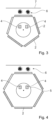
- the multiple sputtering target in the form of a polygonal support tube 1 is equipped with several outer surfaces 3 for receiving targets 2 , with a magnet bar 4 being located in a free space 5 within the polygonal support tube 1 .
- the free space 5 extends longitudinally through the center of the support tube 1 and preferably has a circular cross-section.
- In 1 shows a polygonal support tube 1 of a multiple sputtering target with a triple target system that can be rotated in angular steps and has three targets 2, which are each attached individually to an outer surface 3 of the support tube 1 with a triangular cross-section, the targets 2 being made of the same, or preferably of can be made of different materials.
- the spatially fixed magnet bar 4 which is positioned above the free space 5, ie above its axis of symmetry. With the magnet bar 4, two plasma clouds 6 are generated in front of the target 2 located on top of the carrier tube 1, with the help of which a substrate 7 located above the plasma clouds 6 or guided past is coated with the material sputtered off the target 2 in the sputter-up process becomes.
- the sputter-up method has the advantage that mainly sputtered particles accelerated upwards are deposited on the substrate 7 .
- Figure 2a shows a polygonal support tube 1 with a square cross-section with four longitudinal outer surfaces 3 on each of which a target 2 is attached.
- magnet bar 4 is located above its axis of symmetry.
- Figure 2b is a multiple sputtering target with a polygonal support tube 1 with a structure similar to that in FIG 1 , 2a , but shown with four longitudinal outer surfaces 3 with beveled edges 3.1 of the polygonal support tube 1.
- the 3 shows a multiple sputtering target with a polygonal support tube 1 with a structure as in FIG 1 , but as a penta target system with five longitudinal outer surfaces 3 of the carrier tube 1 for receiving a maximum of five targets 2.
- FIG. 4 Furthermore shows 4 a multiple sputtering target with a polygonal support tube 1 with a structure as in 1 , but with a hexa target system with six longitudinal outer surfaces 3 for holding a total of six targets 2.
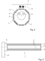
- figure 5 shows a multiple sputtering target with a polygonal support tube 1 with a structure as in 1 , but with an Okta target system with eight longitudinal outer surfaces 3 for receiving one target 2 each.
- the magnet bar 4 is located in the free space 5 above its axis of symmetry, with the free space 5 extending centrally through the support tube 1 .
- the polygonal support tube 1 has a particularly large diameter in order to prevent the distance between the magnet bar 4 in the polygonal support tube 1 and the target 2 on the outer surface 3 of the support tube 1 from becoming too large and thereby the intensity of the plasma clouds 7 would be weakened. In this case, the stated distance should be reduced.
- the different hatchings of the targets 2 attached to the outer surfaces 3 of the support tube 1 are intended to symbolize different materials.
- the support tube 1 simply has to be rotated in equal angular steps until the desired target 2 is positioned above the magnet bar 4 .
- the required plasma clouds 6 then arise during operation of the magnet bar 4 in front of the target 2 located above.
- the polygonal support tubes 1 with different cross-sections can be operated with a commercially available magnetron end block 8 via a connecting element 9, with inside the support tube 1 a spatially fixed magnet bar 4 of a conventional tubular target can be used.
- 6 shows a side view of a hexagonal support tube 1 with the targets 2 located on the outer surfaces 3.
- Particularly long support tubes 1 can be stored with their free end in a counter bearing, not shown, in order to limit deflection to a minimum.
- the sputtering plasma required for sputtering is generated due to the magnetic field by the magnet bar 4 in the vicinity of the target surface.
- the carrier tube 1 By rotating the carrier tube 1 with the targets 2 located on it, different or identical materials can be sputtered off one after the other relative to the magnet bar 3 - depending on how the targets 2 are distributed on the outer surfaces 3 of the carrier tube 1 - and a substrate 7 guided past can be coated accordingly.
- an oscillating movement of the polygonal support tube 1 or the magnet bar 4 can achieve an expanded target ablation field, thereby achieving better utilization of the targets 2.
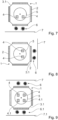
- sputtering methods such as the sputter-down method
- the magnet bar 4 can be easily implemented with the multiple sputtering target in conjunction with the polygonal support tube 1 described above by pivoting the magnet bar 4 downwards by 180° about an imaginary pivot axis, so that the magnet bar 4 is below the axis of symmetry of the free space 5.
- the magnet bar 4 is to be positioned in the free space 5 pointing downwards, so that the plasma clouds 6 form in front of a target 2 located below on the support tube 1 .
- the particles sputtered off the target 2 are deposited on a substrate 7 to be coated, which is guided past the plasma clouds 6 . ( 7 )
- the magnet bar 4 would have to be brought into a lateral position by 90°, so that the plasma clouds 6 form in front of the target 2 to be positioned laterally.
- the substrate 7 to be coated would have to be positioned laterally perpendicularly in front of the plasma clouds 6 or guided past it.
- a particular embodiment of the invention is 9 shown.
- the polygonal support tube 1 described here is equipped with a central free space 5 in which two magnet bars 4, 4.1 are arranged above and below the axis of symmetry. In this way, two plasma clouds 6, 6.1 can be formed at the top and bottom in front of the corresponding targets 2, past which a substrate 7, 7.1 can be moved or positioned.
- a prerequisite for this embodiment of the invention is that the polygonal support tube 1 has an even number of outer surfaces 3 .
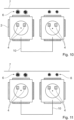
- FIGS 10 to 11 are special embodiments with multiple sputtering targets or in combination with one conventional tubular magnetron in order to be able to carry out a bipolar process in a common vacuum chamber. This significantly increases the flexibility of a sputtering system.
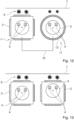
- a parallel arrangement of two multiple sputtering targets according to the invention with a common MF power supply 10 for depositing the same materials on a substrate 7 is shown in 10 shown.
- FIG. 11 shows basically the same parallel arrangement of two multiple sputtering targets with a common MF power supply for the deposition of different materials on a substrate, with the polygonal support tube 1 on the right according to the drawing being rotated upwards into the coating position with another target 2. This allows the deposition of different material combinations on a substrate 7.
- a special variant shows 12 with a simultaneously operated parallel arrangement of a multiple sputter target according to the invention and a conventional tube magnetron 11 with a common MF power supply 10 for the deposition of different materials on a substrate 7.
- the tube magnetron 11 contains a central free space 5 in which a magnet bar 4 is located and the is surrounded by a tubular target 12.
- a combination of a multiple sputtering target according to the invention with a conventional planar magnetron (not shown) and with a common MF power supply in a common vacuum chamber is also possible without any problems.
- the deposition of material combinations on the substrate to be guided past is also possible with this combination.
- polygonal support tubes 1 can also have the cross-sectional shapes shown in the other figures.
- magnet bars 4 Standard magnet bars or any other suitable magnet bars in free space 5 can be used as magnet bars 4 .
- connection elements 9 required for operation on a magnetron end block 8 and in the support bearing can be attached to the support tube 1 by welding, or a corresponding connection element 9 is used as an adapter.
- magnetron end block 7 instead of the commercially available magnetron end block 7 other suitable recording devices with adjusting motors can also be used, provided that an angularly precise rotational movement is generated in order to bring the various targets 2 on the polygonal support tube 1 into the correct position, ie parallel to the substrate 7, 7.1 to be coated.
- a pendulum movement of the polygonal support tube 1 of the multiple target around the fixed magnet bar is also conceivable.
Landscapes
- Chemical & Material Sciences (AREA)
- Engineering & Computer Science (AREA)
- Physics & Mathematics (AREA)
- Plasma & Fusion (AREA)
- Analytical Chemistry (AREA)
- Chemical Kinetics & Catalysis (AREA)
- Materials Engineering (AREA)
- Mechanical Engineering (AREA)
- Metallurgy (AREA)
- Organic Chemistry (AREA)
- Physical Vapour Deposition (AREA)
Applications Claiming Priority (1)
| Application Number | Priority Date | Filing Date | Title |
|---|---|---|---|
| DE102021120332 | 2021-08-04 |
Publications (1)
| Publication Number | Publication Date |
|---|---|
| EP4131332A1 true EP4131332A1 (de) | 2023-02-08 |
Family
ID=82839102
Family Applications (1)
| Application Number | Title | Priority Date | Filing Date |
|---|---|---|---|
| EP22188642.7A Withdrawn EP4131332A1 (de) | 2021-08-04 | 2022-08-04 | Mehrfach-sputtertarget |
Country Status (5)
| Country | Link |
|---|---|
| US (1) | US20230044831A1 (enExample) |
| EP (1) | EP4131332A1 (enExample) |
| JP (1) | JP2023024280A (enExample) |
| CN (1) | CN115704088A (enExample) |
| TW (1) | TW202307240A (enExample) |
Cited By (1)
| Publication number | Priority date | Publication date | Assignee | Title |
|---|---|---|---|---|
| WO2024260745A1 (de) * | 2023-06-22 | 2024-12-26 | Fhr Anlagenbau Gmbh | Vakuumbeschichtungsanlage und verfahren zum beschichten von substraten mit erhöhter beschichtungsrate |
Citations (5)
| Publication number | Priority date | Publication date | Assignee | Title |
|---|---|---|---|---|
| US4443318A (en) * | 1983-08-17 | 1984-04-17 | Shatterproof Glass Corporation | Cathodic sputtering apparatus |
| DE19830223C1 (de) * | 1998-07-07 | 1999-11-04 | Techno Coat Oberflaechentechni | Vorrichtung und Verfahren zum mehrlagigen PVD - Beschichten von Substraten |
| JP2003183827A (ja) * | 2001-12-19 | 2003-07-03 | Yamaguchi Technology Licensing Organization Ltd | 薄膜作製装置 |
| WO2003081634A2 (de) | 2002-03-22 | 2003-10-02 | Von Ardenne Anlagentechnik Gmbh | Rohrmagnetron |
| DE102008048785A1 (de) | 2007-09-24 | 2009-04-09 | Von Ardenne Anlagentechnik Gmbh | Magnetronanordnung mit abgeschirmter Targethalterung |
-
2022
- 2022-06-17 JP JP2022097797A patent/JP2023024280A/ja active Pending
- 2022-07-29 TW TW111128522A patent/TW202307240A/zh unknown
- 2022-08-02 US US17/816,781 patent/US20230044831A1/en not_active Abandoned
- 2022-08-03 CN CN202210927169.6A patent/CN115704088A/zh active Pending
- 2022-08-04 EP EP22188642.7A patent/EP4131332A1/de not_active Withdrawn
Patent Citations (5)
| Publication number | Priority date | Publication date | Assignee | Title |
|---|---|---|---|---|
| US4443318A (en) * | 1983-08-17 | 1984-04-17 | Shatterproof Glass Corporation | Cathodic sputtering apparatus |
| DE19830223C1 (de) * | 1998-07-07 | 1999-11-04 | Techno Coat Oberflaechentechni | Vorrichtung und Verfahren zum mehrlagigen PVD - Beschichten von Substraten |
| JP2003183827A (ja) * | 2001-12-19 | 2003-07-03 | Yamaguchi Technology Licensing Organization Ltd | 薄膜作製装置 |
| WO2003081634A2 (de) | 2002-03-22 | 2003-10-02 | Von Ardenne Anlagentechnik Gmbh | Rohrmagnetron |
| DE102008048785A1 (de) | 2007-09-24 | 2009-04-09 | Von Ardenne Anlagentechnik Gmbh | Magnetronanordnung mit abgeschirmter Targethalterung |
Cited By (1)
| Publication number | Priority date | Publication date | Assignee | Title |
|---|---|---|---|---|
| WO2024260745A1 (de) * | 2023-06-22 | 2024-12-26 | Fhr Anlagenbau Gmbh | Vakuumbeschichtungsanlage und verfahren zum beschichten von substraten mit erhöhter beschichtungsrate |
Also Published As
| Publication number | Publication date |
|---|---|
| CN115704088A (zh) | 2023-02-17 |
| TW202307240A (zh) | 2023-02-16 |
| US20230044831A1 (en) | 2023-02-09 |
| JP2023024280A (ja) | 2023-02-16 |
Similar Documents
| Publication | Publication Date | Title |
|---|---|---|
| EP0211057B1 (de) | Sputteranlage zum reaktiven beschichten eines substrates mit hartstoffen | |
| EP0165565B1 (de) | Vakuum-Plasma-Beschichtungsanlage | |
| DE3506227A1 (de) | Anordnung zur beschichtung von substraten mittels kathodenzerstaeubung | |
| EP0535019A1 (de) | Verfahren und vorrichtung zum beschichten von substratmaterial. | |
| CH683777A5 (de) | Ortsfeste Magnetron-Zerstäubungskathode für Vakuumbeschichtungsanlagen. | |
| EP1144714A1 (de) | Verfahren und einrichtung zum beschichten von substraten mittels bipolarer puls-magnetron-zerstäubung und deren anwendung | |
| EP1626433B1 (de) | Magnetronsputtereinrichtung, Zylinderkathode und Verfahren zur Aufbringung von dünnen Mehrkomponentenschichten auf einem Substrat | |
| DE4117367C2 (de) | Verfahren zur Erzeugung eines homogenen Abtragprofils auf einem rotierenden Target einer Sputtervorrichtung | |
| EP4131332A1 (de) | Mehrfach-sputtertarget | |
| EP1775353B1 (de) | Beschichtungsanlage und Verfahren zum Betrieb einer Beschichtungsanlage | |
| EP1673488B1 (de) | Modulare vorrichtung zur beschichtung von oberflächen | |
| DE69128544T2 (de) | Verfahren und vorrichtung zur sputtenbeschichtung mit rotierender magnetischer kathode | |
| EP3868917A1 (de) | Vorrichtung, verfahren und verwendung zur beschichtung von linsen | |
| DE10215369B4 (de) | Kathodenzerstäubungsgerät zur Ausbildung eines Metallfilms unter Verwendung eines Magnetfeldes | |
| DE19850217C1 (de) | Verfahren und Vorrichtung zur Beschichtung von Substraten im Vakuum | |
| DE102004006849B4 (de) | Vorrichtung zum Beschichten von Substraten | |
| WO2000016373A1 (de) | Targetanordnung für eine arc-verdampfungs-kammer | |
| EP0955667A1 (de) | Target für eine Kathodenzerstäubungsvorrichtung zur Herstellung dünner Schichten | |
| DE102004027989A1 (de) | Werkstückträgervorrichtung zum Halten von Werkstücken und Behandlungsvorrichtung | |
| DE4443740B4 (de) | Vorrichtung zum Beschichten von Substraten | |
| EP1889280A1 (de) | Sputter-magnetron | |
| EP0940482B1 (de) | Vakuum-Plasma-Beschichtungsanlage und Anwendung derselben | |
| DE3503397A1 (de) | Sputteranlage zum reaktiven beschichten eines substrates mit hartstoffen | |
| DE102007049649B4 (de) | Vorrichtung und Verfahren zur Ausbildung von Beschichtungen auf Substraten innerhalb von Vakuumkammern | |
| DE102020111792A1 (de) | Magnetsystem eines Rohrmagnetrons und Rohrmagnetron |
Legal Events
| Date | Code | Title | Description |
|---|---|---|---|
| PUAI | Public reference made under article 153(3) epc to a published international application that has entered the european phase |
Free format text: ORIGINAL CODE: 0009012 |
|
| STAA | Information on the status of an ep patent application or granted ep patent |
Free format text: STATUS: THE APPLICATION HAS BEEN PUBLISHED |
|
| AK | Designated contracting states |
Kind code of ref document: A1 Designated state(s): AL AT BE BG CH CY CZ DE DK EE ES FI FR GB GR HR HU IE IS IT LI LT LU LV MC MK MT NL NO PL PT RO RS SE SI SK SM TR |
|
| STAA | Information on the status of an ep patent application or granted ep patent |
Free format text: STATUS: THE APPLICATION IS DEEMED TO BE WITHDRAWN |
|
| 18D | Application deemed to be withdrawn |
Effective date: 20230809 |