EP4130749A1 - System und verfahren zur probenvorbereitung bei der gmr-basierten detektion von biomarkern - Google Patents
System und verfahren zur probenvorbereitung bei der gmr-basierten detektion von biomarkern Download PDFInfo
- Publication number
- EP4130749A1 EP4130749A1 EP22182712.4A EP22182712A EP4130749A1 EP 4130749 A1 EP4130749 A1 EP 4130749A1 EP 22182712 A EP22182712 A EP 22182712A EP 4130749 A1 EP4130749 A1 EP 4130749A1
- Authority
- EP
- European Patent Office
- Prior art keywords
- card
- sample
- sample processing
- processing card
- cartridge assembly
- Prior art date
- Legal status (The legal status is an assumption and is not a legal conclusion. Google has not performed a legal analysis and makes no representation as to the accuracy of the status listed.)
- Pending
Links
Images


Classifications
-
- B—PERFORMING OPERATIONS; TRANSPORTING
- B01—PHYSICAL OR CHEMICAL PROCESSES OR APPARATUS IN GENERAL
- B01L—CHEMICAL OR PHYSICAL LABORATORY APPARATUS FOR GENERAL USE
- B01L3/00—Containers or dishes for laboratory use, e.g. laboratory glassware; Droppers
- B01L3/50—Containers for the purpose of retaining a material to be analysed, e.g. test tubes
- B01L3/502—Containers for the purpose of retaining a material to be analysed, e.g. test tubes with fluid transport, e.g. in multi-compartment structures
- B01L3/5027—Containers for the purpose of retaining a material to be analysed, e.g. test tubes with fluid transport, e.g. in multi-compartment structures by integrated microfluidic structures, i.e. dimensions of channels and chambers are such that surface tension forces are important, e.g. lab-on-a-chip
- B01L3/502715—Containers for the purpose of retaining a material to be analysed, e.g. test tubes with fluid transport, e.g. in multi-compartment structures by integrated microfluidic structures, i.e. dimensions of channels and chambers are such that surface tension forces are important, e.g. lab-on-a-chip characterised by interfacing components, e.g. fluidic, electrical, optical or mechanical interfaces
-
- G—PHYSICS
- G01—MEASURING; TESTING
- G01N—INVESTIGATING OR ANALYSING MATERIALS BY DETERMINING THEIR CHEMICAL OR PHYSICAL PROPERTIES
- G01N27/00—Investigating or analysing materials by the use of electric, electrochemical, or magnetic means
- G01N27/02—Investigating or analysing materials by the use of electric, electrochemical, or magnetic means by investigating impedance
- G01N27/04—Investigating or analysing materials by the use of electric, electrochemical, or magnetic means by investigating impedance by investigating resistance
- G01N27/12—Investigating or analysing materials by the use of electric, electrochemical, or magnetic means by investigating impedance by investigating resistance of a solid body in dependence upon absorption of a fluid; of a solid body in dependence upon reaction with a fluid, for detecting components in the fluid
-
- B—PERFORMING OPERATIONS; TRANSPORTING
- B01—PHYSICAL OR CHEMICAL PROCESSES OR APPARATUS IN GENERAL
- B01L—CHEMICAL OR PHYSICAL LABORATORY APPARATUS FOR GENERAL USE
- B01L3/00—Containers or dishes for laboratory use, e.g. laboratory glassware; Droppers
- B01L3/50—Containers for the purpose of retaining a material to be analysed, e.g. test tubes
- B01L3/502—Containers for the purpose of retaining a material to be analysed, e.g. test tubes with fluid transport, e.g. in multi-compartment structures
- B01L3/5027—Containers for the purpose of retaining a material to be analysed, e.g. test tubes with fluid transport, e.g. in multi-compartment structures by integrated microfluidic structures, i.e. dimensions of channels and chambers are such that surface tension forces are important, e.g. lab-on-a-chip
- B01L3/50273—Containers for the purpose of retaining a material to be analysed, e.g. test tubes with fluid transport, e.g. in multi-compartment structures by integrated microfluidic structures, i.e. dimensions of channels and chambers are such that surface tension forces are important, e.g. lab-on-a-chip characterised by the means or forces applied to move the fluids
-
- B—PERFORMING OPERATIONS; TRANSPORTING
- B01—PHYSICAL OR CHEMICAL PROCESSES OR APPARATUS IN GENERAL
- B01L—CHEMICAL OR PHYSICAL LABORATORY APPARATUS FOR GENERAL USE
- B01L3/00—Containers or dishes for laboratory use, e.g. laboratory glassware; Droppers
- B01L3/56—Labware specially adapted for transferring fluids
- B01L3/567—Valves, taps or stop-cocks
-
- G—PHYSICS
- G01—MEASURING; TESTING
- G01N—INVESTIGATING OR ANALYSING MATERIALS BY DETERMINING THEIR CHEMICAL OR PHYSICAL PROPERTIES
- G01N27/00—Investigating or analysing materials by the use of electric, electrochemical, or magnetic means
- G01N27/72—Investigating or analysing materials by the use of electric, electrochemical, or magnetic means by investigating magnetic variables
- G01N27/74—Investigating or analysing materials by the use of electric, electrochemical, or magnetic means by investigating magnetic variables of fluids
- G01N27/745—Investigating or analysing materials by the use of electric, electrochemical, or magnetic means by investigating magnetic variables of fluids for detecting magnetic beads used in biochemical assays
-
- G—PHYSICS
- G01—MEASURING; TESTING
- G01N—INVESTIGATING OR ANALYSING MATERIALS BY DETERMINING THEIR CHEMICAL OR PHYSICAL PROPERTIES
- G01N33/00—Investigating or analysing materials by specific methods not covered by groups G01N1/00 - G01N31/00
- G01N33/18—Water
- G01N33/1813—Water specific cations in water, e.g. heavy metals
-
- G—PHYSICS
- G01—MEASURING; TESTING
- G01N—INVESTIGATING OR ANALYSING MATERIALS BY DETERMINING THEIR CHEMICAL OR PHYSICAL PROPERTIES
- G01N33/00—Investigating or analysing materials by specific methods not covered by groups G01N1/00 - G01N31/00
- G01N33/48—Biological material, e.g. blood, urine; Haemocytometers
- G01N33/483—Physical analysis of biological material
- G01N33/487—Physical analysis of biological material of liquid biological material
- G01N33/48707—Physical analysis of biological material of liquid biological material by electrical means
-
- G—PHYSICS
- G01—MEASURING; TESTING
- G01N—INVESTIGATING OR ANALYSING MATERIALS BY DETERMINING THEIR CHEMICAL OR PHYSICAL PROPERTIES
- G01N33/00—Investigating or analysing materials by specific methods not covered by groups G01N1/00 - G01N31/00
- G01N33/48—Biological material, e.g. blood, urine; Haemocytometers
- G01N33/483—Physical analysis of biological material
- G01N33/487—Physical analysis of biological material of liquid biological material
- G01N33/49—Blood
-
- G—PHYSICS
- G01—MEASURING; TESTING
- G01N—INVESTIGATING OR ANALYSING MATERIALS BY DETERMINING THEIR CHEMICAL OR PHYSICAL PROPERTIES
- G01N33/00—Investigating or analysing materials by specific methods not covered by groups G01N1/00 - G01N31/00
- G01N33/48—Biological material, e.g. blood, urine; Haemocytometers
- G01N33/483—Physical analysis of biological material
- G01N33/487—Physical analysis of biological material of liquid biological material
- G01N33/493—Physical analysis of biological material of liquid biological material urine
-
- G—PHYSICS
- G01—MEASURING; TESTING
- G01N—INVESTIGATING OR ANALYSING MATERIALS BY DETERMINING THEIR CHEMICAL OR PHYSICAL PROPERTIES
- G01N33/00—Investigating or analysing materials by specific methods not covered by groups G01N1/00 - G01N31/00
- G01N33/48—Biological material, e.g. blood, urine; Haemocytometers
- G01N33/50—Chemical analysis of biological material, e.g. blood, urine; Testing involving biospecific ligand binding methods; Immunological testing
- G01N33/53—Immunoassay; Biospecific binding assay; Materials therefor
- G01N33/543—Immunoassay; Biospecific binding assay; Materials therefor with an insoluble carrier for immobilising immunochemicals
- G01N33/54306—Solid-phase reaction mechanisms
-
- G—PHYSICS
- G01—MEASURING; TESTING
- G01N—INVESTIGATING OR ANALYSING MATERIALS BY DETERMINING THEIR CHEMICAL OR PHYSICAL PROPERTIES
- G01N33/00—Investigating or analysing materials by specific methods not covered by groups G01N1/00 - G01N31/00
- G01N33/48—Biological material, e.g. blood, urine; Haemocytometers
- G01N33/50—Chemical analysis of biological material, e.g. blood, urine; Testing involving biospecific ligand binding methods; Immunological testing
- G01N33/53—Immunoassay; Biospecific binding assay; Materials therefor
- G01N33/543—Immunoassay; Biospecific binding assay; Materials therefor with an insoluble carrier for immobilising immunochemicals
- G01N33/54313—Immunoassay; Biospecific binding assay; Materials therefor with an insoluble carrier for immobilising immunochemicals the carrier being characterised by its particulate form
- G01N33/54326—Magnetic particles
-
- G—PHYSICS
- G01—MEASURING; TESTING
- G01N—INVESTIGATING OR ANALYSING MATERIALS BY DETERMINING THEIR CHEMICAL OR PHYSICAL PROPERTIES
- G01N33/00—Investigating or analysing materials by specific methods not covered by groups G01N1/00 - G01N31/00
- G01N33/48—Biological material, e.g. blood, urine; Haemocytometers
- G01N33/50—Chemical analysis of biological material, e.g. blood, urine; Testing involving biospecific ligand binding methods; Immunological testing
- G01N33/53—Immunoassay; Biospecific binding assay; Materials therefor
- G01N33/543—Immunoassay; Biospecific binding assay; Materials therefor with an insoluble carrier for immobilising immunochemicals
- G01N33/54366—Apparatus specially adapted for solid-phase testing
-
- G—PHYSICS
- G01—MEASURING; TESTING
- G01N—INVESTIGATING OR ANALYSING MATERIALS BY DETERMINING THEIR CHEMICAL OR PHYSICAL PROPERTIES
- G01N33/00—Investigating or analysing materials by specific methods not covered by groups G01N1/00 - G01N31/00
- G01N33/48—Biological material, e.g. blood, urine; Haemocytometers
- G01N33/50—Chemical analysis of biological material, e.g. blood, urine; Testing involving biospecific ligand binding methods; Immunological testing
- G01N33/84—Chemical analysis of biological material, e.g. blood, urine; Testing involving biospecific ligand binding methods; Immunological testing involving inorganic compounds or pH
-
- G—PHYSICS
- G01—MEASURING; TESTING
- G01N—INVESTIGATING OR ANALYSING MATERIALS BY DETERMINING THEIR CHEMICAL OR PHYSICAL PROPERTIES
- G01N35/00—Automatic analysis not limited to methods or materials provided for in any single one of groups G01N1/00 - G01N33/00; Handling materials therefor
- G01N35/00029—Automatic analysis not limited to methods or materials provided for in any single one of groups G01N1/00 - G01N33/00; Handling materials therefor provided with flat sample substrates, e.g. slides
-
- G—PHYSICS
- G01—MEASURING; TESTING
- G01N—INVESTIGATING OR ANALYSING MATERIALS BY DETERMINING THEIR CHEMICAL OR PHYSICAL PROPERTIES
- G01N35/00—Automatic analysis not limited to methods or materials provided for in any single one of groups G01N1/00 - G01N33/00; Handling materials therefor
- G01N35/10—Devices for transferring samples or any liquids to, in, or from, the analysis apparatus, e.g. suction devices, injection devices
- G01N35/1095—Devices for transferring samples or any liquids to, in, or from, the analysis apparatus, e.g. suction devices, injection devices for supplying the samples to flow-through analysers
- G01N35/1097—Devices for transferring samples or any liquids to, in, or from, the analysis apparatus, e.g. suction devices, injection devices for supplying the samples to flow-through analysers characterised by the valves
-
- G—PHYSICS
- G01—MEASURING; TESTING
- G01R—MEASURING ELECTRIC VARIABLES; MEASURING MAGNETIC VARIABLES
- G01R33/00—Arrangements or instruments for measuring magnetic variables
- G01R33/0023—Electronic aspects, e.g. circuits for stimulation, evaluation, control; Treating the measured signals; calibration
- G01R33/0041—Electronic aspects, e.g. circuits for stimulation, evaluation, control; Treating the measured signals; calibration using feed-back or modulation techniques
-
- G—PHYSICS
- G01—MEASURING; TESTING
- G01R—MEASURING ELECTRIC VARIABLES; MEASURING MAGNETIC VARIABLES
- G01R33/00—Arrangements or instruments for measuring magnetic variables
- G01R33/02—Measuring direction or magnitude of magnetic fields or magnetic flux
- G01R33/06—Measuring direction or magnitude of magnetic fields or magnetic flux using galvano-magnetic devices
- G01R33/09—Magnetoresistive devices
- G01R33/091—Constructional adaptation of the sensor to specific applications
-
- G—PHYSICS
- G01—MEASURING; TESTING
- G01R—MEASURING ELECTRIC VARIABLES; MEASURING MAGNETIC VARIABLES
- G01R33/00—Arrangements or instruments for measuring magnetic variables
- G01R33/02—Measuring direction or magnitude of magnetic fields or magnetic flux
- G01R33/06—Measuring direction or magnitude of magnetic fields or magnetic flux using galvano-magnetic devices
- G01R33/09—Magnetoresistive devices
- G01R33/093—Magnetoresistive devices using multilayer structures, e.g. giant magnetoresistance sensors
-
- G—PHYSICS
- G01—MEASURING; TESTING
- G01R—MEASURING ELECTRIC VARIABLES; MEASURING MAGNETIC VARIABLES
- G01R33/00—Arrangements or instruments for measuring magnetic variables
- G01R33/12—Measuring magnetic properties of articles or specimens of solids or fluids
- G01R33/1269—Measuring magnetic properties of articles or specimens of solids or fluids of molecules labeled with magnetic beads
-
- G—PHYSICS
- G01—MEASURING; TESTING
- G01R—MEASURING ELECTRIC VARIABLES; MEASURING MAGNETIC VARIABLES
- G01R33/00—Arrangements or instruments for measuring magnetic variables
- G01R33/12—Measuring magnetic properties of articles or specimens of solids or fluids
- G01R33/1276—Measuring magnetic properties of articles or specimens of solids or fluids of magnetic particles, e.g. imaging of magnetic nanoparticles
-
- B—PERFORMING OPERATIONS; TRANSPORTING
- B01—PHYSICAL OR CHEMICAL PROCESSES OR APPARATUS IN GENERAL
- B01L—CHEMICAL OR PHYSICAL LABORATORY APPARATUS FOR GENERAL USE
- B01L2200/00—Solutions for specific problems relating to chemical or physical laboratory apparatus
- B01L2200/02—Adapting objects or devices to another
- B01L2200/026—Fluid interfacing between devices or objects, e.g. connectors, inlet details
- B01L2200/027—Fluid interfacing between devices or objects, e.g. connectors, inlet details for microfluidic devices
-
- B—PERFORMING OPERATIONS; TRANSPORTING
- B01—PHYSICAL OR CHEMICAL PROCESSES OR APPARATUS IN GENERAL
- B01L—CHEMICAL OR PHYSICAL LABORATORY APPARATUS FOR GENERAL USE
- B01L2200/00—Solutions for specific problems relating to chemical or physical laboratory apparatus
- B01L2200/04—Exchange or ejection of cartridges, containers or reservoirs
-
- B—PERFORMING OPERATIONS; TRANSPORTING
- B01—PHYSICAL OR CHEMICAL PROCESSES OR APPARATUS IN GENERAL
- B01L—CHEMICAL OR PHYSICAL LABORATORY APPARATUS FOR GENERAL USE
- B01L2200/00—Solutions for specific problems relating to chemical or physical laboratory apparatus
- B01L2200/06—Fluid handling related problems
- B01L2200/0684—Venting, avoiding backpressure, avoid gas bubbles
-
- B—PERFORMING OPERATIONS; TRANSPORTING
- B01—PHYSICAL OR CHEMICAL PROCESSES OR APPARATUS IN GENERAL
- B01L—CHEMICAL OR PHYSICAL LABORATORY APPARATUS FOR GENERAL USE
- B01L2200/00—Solutions for specific problems relating to chemical or physical laboratory apparatus
- B01L2200/14—Process control and prevention of errors
-
- B—PERFORMING OPERATIONS; TRANSPORTING
- B01—PHYSICAL OR CHEMICAL PROCESSES OR APPARATUS IN GENERAL
- B01L—CHEMICAL OR PHYSICAL LABORATORY APPARATUS FOR GENERAL USE
- B01L2200/00—Solutions for specific problems relating to chemical or physical laboratory apparatus
- B01L2200/16—Reagents, handling or storing thereof
-
- B—PERFORMING OPERATIONS; TRANSPORTING
- B01—PHYSICAL OR CHEMICAL PROCESSES OR APPARATUS IN GENERAL
- B01L—CHEMICAL OR PHYSICAL LABORATORY APPARATUS FOR GENERAL USE
- B01L2300/00—Additional constructional details
- B01L2300/02—Identification, exchange or storage of information
- B01L2300/025—Displaying results or values with integrated means
-
- B—PERFORMING OPERATIONS; TRANSPORTING
- B01—PHYSICAL OR CHEMICAL PROCESSES OR APPARATUS IN GENERAL
- B01L—CHEMICAL OR PHYSICAL LABORATORY APPARATUS FOR GENERAL USE
- B01L2300/00—Additional constructional details
- B01L2300/06—Auxiliary integrated devices, integrated components
- B01L2300/0627—Sensor or part of a sensor is integrated
- B01L2300/0663—Whole sensors
-
- B—PERFORMING OPERATIONS; TRANSPORTING
- B01—PHYSICAL OR CHEMICAL PROCESSES OR APPARATUS IN GENERAL
- B01L—CHEMICAL OR PHYSICAL LABORATORY APPARATUS FOR GENERAL USE
- B01L2300/00—Additional constructional details
- B01L2300/06—Auxiliary integrated devices, integrated components
- B01L2300/0681—Filter
-
- B—PERFORMING OPERATIONS; TRANSPORTING
- B01—PHYSICAL OR CHEMICAL PROCESSES OR APPARATUS IN GENERAL
- B01L—CHEMICAL OR PHYSICAL LABORATORY APPARATUS FOR GENERAL USE
- B01L2300/00—Additional constructional details
- B01L2300/08—Geometry, shape and general structure
- B01L2300/0809—Geometry, shape and general structure rectangular shaped
- B01L2300/0816—Cards, e.g. flat sample carriers usually with flow in two horizontal directions
-
- B—PERFORMING OPERATIONS; TRANSPORTING
- B01—PHYSICAL OR CHEMICAL PROCESSES OR APPARATUS IN GENERAL
- B01L—CHEMICAL OR PHYSICAL LABORATORY APPARATUS FOR GENERAL USE
- B01L2300/00—Additional constructional details
- B01L2300/08—Geometry, shape and general structure
- B01L2300/0809—Geometry, shape and general structure rectangular shaped
- B01L2300/0819—Microarrays; Biochips
-
- B—PERFORMING OPERATIONS; TRANSPORTING
- B01—PHYSICAL OR CHEMICAL PROCESSES OR APPARATUS IN GENERAL
- B01L—CHEMICAL OR PHYSICAL LABORATORY APPARATUS FOR GENERAL USE
- B01L2300/00—Additional constructional details
- B01L2300/08—Geometry, shape and general structure
- B01L2300/0861—Configuration of multiple channels and/or chambers in a single devices
- B01L2300/0883—Serpentine channels
-
- B—PERFORMING OPERATIONS; TRANSPORTING
- B01—PHYSICAL OR CHEMICAL PROCESSES OR APPARATUS IN GENERAL
- B01L—CHEMICAL OR PHYSICAL LABORATORY APPARATUS FOR GENERAL USE
- B01L2300/00—Additional constructional details
- B01L2300/08—Geometry, shape and general structure
- B01L2300/0887—Laminated structure
-
- B—PERFORMING OPERATIONS; TRANSPORTING
- B01—PHYSICAL OR CHEMICAL PROCESSES OR APPARATUS IN GENERAL
- B01L—CHEMICAL OR PHYSICAL LABORATORY APPARATUS FOR GENERAL USE
- B01L2300/00—Additional constructional details
- B01L2300/12—Specific details about materials
- B01L2300/123—Flexible; Elastomeric
-
- B—PERFORMING OPERATIONS; TRANSPORTING
- B01—PHYSICAL OR CHEMICAL PROCESSES OR APPARATUS IN GENERAL
- B01L—CHEMICAL OR PHYSICAL LABORATORY APPARATUS FOR GENERAL USE
- B01L2300/00—Additional constructional details
- B01L2300/14—Means for pressure control
-
- B—PERFORMING OPERATIONS; TRANSPORTING
- B01—PHYSICAL OR CHEMICAL PROCESSES OR APPARATUS IN GENERAL
- B01L—CHEMICAL OR PHYSICAL LABORATORY APPARATUS FOR GENERAL USE
- B01L2400/00—Moving or stopping fluids
- B01L2400/04—Moving fluids with specific forces or mechanical means
- B01L2400/0403—Moving fluids with specific forces or mechanical means specific forces
- B01L2400/043—Moving fluids with specific forces or mechanical means specific forces magnetic forces
-
- B—PERFORMING OPERATIONS; TRANSPORTING
- B01—PHYSICAL OR CHEMICAL PROCESSES OR APPARATUS IN GENERAL
- B01L—CHEMICAL OR PHYSICAL LABORATORY APPARATUS FOR GENERAL USE
- B01L2400/00—Moving or stopping fluids
- B01L2400/04—Moving fluids with specific forces or mechanical means
- B01L2400/0475—Moving fluids with specific forces or mechanical means specific mechanical means and fluid pressure
- B01L2400/0487—Moving fluids with specific forces or mechanical means specific mechanical means and fluid pressure fluid pressure, pneumatics
-
- B—PERFORMING OPERATIONS; TRANSPORTING
- B01—PHYSICAL OR CHEMICAL PROCESSES OR APPARATUS IN GENERAL
- B01L—CHEMICAL OR PHYSICAL LABORATORY APPARATUS FOR GENERAL USE
- B01L2400/00—Moving or stopping fluids
- B01L2400/06—Valves, specific forms thereof
-
- G—PHYSICS
- G01—MEASURING; TESTING
- G01N—INVESTIGATING OR ANALYSING MATERIALS BY DETERMINING THEIR CHEMICAL OR PHYSICAL PROPERTIES
- G01N1/00—Sampling; Preparing specimens for investigation
- G01N1/28—Preparing specimens for investigation including physical details of (bio-)chemical methods covered elsewhere, e.g. G01N33/50, C12Q
- G01N1/38—Diluting, dispersing or mixing samples
- G01N2001/386—Other diluting or mixing processes
-
- G—PHYSICS
- G01—MEASURING; TESTING
- G01N—INVESTIGATING OR ANALYSING MATERIALS BY DETERMINING THEIR CHEMICAL OR PHYSICAL PROPERTIES
- G01N35/00—Automatic analysis not limited to methods or materials provided for in any single one of groups G01N1/00 - G01N33/00; Handling materials therefor
- G01N35/00029—Automatic analysis not limited to methods or materials provided for in any single one of groups G01N1/00 - G01N33/00; Handling materials therefor provided with flat sample substrates, e.g. slides
- G01N2035/00099—Characterised by type of test elements
- G01N2035/00148—Test cards, e.g. Biomerieux or McDonnel multiwell test cards
-
- G—PHYSICS
- G01—MEASURING; TESTING
- G01N—INVESTIGATING OR ANALYSING MATERIALS BY DETERMINING THEIR CHEMICAL OR PHYSICAL PROPERTIES
- G01N35/00—Automatic analysis not limited to methods or materials provided for in any single one of groups G01N1/00 - G01N33/00; Handling materials therefor
- G01N35/0098—Automatic analysis not limited to methods or materials provided for in any single one of groups G01N1/00 - G01N33/00; Handling materials therefor involving analyte bound to insoluble magnetic carrier, e.g. using magnetic separation
Definitions
- the present disclosure is generally related to a system for the detection of analytes.
- the present invention relates to a mobile system including a unit and a cartridge assembly that can be used for the detection of various analytes such as metal, biomarkers, and the like.
- a card to test for biomarker(s), metal, etc. in a blood sample.
- Adding a blood sample to known cards generally relies simply on lateral flow of the blood sample into the card before a reading is performed.
- current assay systems in the medical market generally rely on capillary separation of a whole blood sample, which generally limits detection methodology to optical analysis or visual testing.
- Embodiments herein relate to devices for detection of analytes in a sample with magnetoresistive sensor technologies.
- the devices, systems, and features are described with respect to utilizing a giant magnetoresistance (GMR) sensor platform.
- GMR giant magnetoresistance
- the cartridge assembly includes: a sample processing card having: an injection port for receiving the test sample within a body of the card; at least one metering chamber for receiving the test sample; a mixing material source for introducing one or more mixing materials to the at least one metering chamber; fluid communication channels fluidly connecting the injection port and the mixing material source to the at least one metering chamber; and at least one output port fluidly connected to the at least one metering chamber for delivering the test sample and the one or more mixing materials to the sensor.
- the cartridge assembly also includes a substrate attached to the sample processing card.
- the substrate has associated therewith: the sensor for sensing analytes in the test sample, the sensor being configured to receive the test sample and the one or more mixing materials via the at least one output port; electrical contact portions configured to establish an electrical connection with the reader unit; and a memory chip for storing information related to processing of the test sample within the sample processing card.
- the cartridge assembly further includes a pneumatic interface comprising at least one pneumatic control port and corresponding communication channel fluidly connected to the at least one metering chamber, the pneumatic interface configured for connection to an off-board pneumatic system of a reader unit, the pneumatic interface configured to enable application of positive and negative pressurized fluid to the sample processing card to move the test sample and one or more mixing materials therein.
- the memory chip may store a pneumatic system protocol that includes steps and settings for selectively applying pressure to the pneumatic interface and thus delivering at least the test sample from the sample processing card to the sensor.
- Another aspect provides a method of using the cartridge assembly described above, including injecting the test sample into the injection port; establishing the electrical connection with the reader unit; and selectively applying pressurized air to the pneumatic interface using the off-board pneumatic system to move the test sample and the one or more mixing materials within the communication channels and to the sensor.
- this disclosure relates to a sample handling system (or “system” as noted throughout this disclosure) which may be used for detecting presence of an analyte (or analytes) such as metal, biomarkers, and the like, in a sample.
- this system depicted as system 300 in Fig.
- a sample handling system or "cartridge assembly” that includes sample preparation microfluidic channel(s) and at least one sensing device (or sensor) for sensing biomarkers / analytes in a test sample
- a data processing and display device or “cartridge reader unit” that includes a processor or controller for processing any sensed data of the sensing device of the cartridge assembly and a display for displaying a detection event.
- these components may include variable features including, without limitation, one or more reagent cartridges, a cartridge for waste, and a flow control system which may be, for example, a pneumatic flow controller.
- the process for preparing a sample in the cartridge assembly in order for detection of analytes, biomarkers, etc. to happen by the assembly and output via the cartridge reader unit, is as-follows:
- a raw patient sample is loaded onto a card, optionally filtered via a filter membrane, after which a negative pressure generated by off-card pneumatics filters the sample into a separated test sample (e.g., plasma).
- This separated test sample is quantitated on-card through channel geometry.
- the sample is prepared on card by interaction with mixing materials (e.g., reagent(s) (which may be dry or wet), buffer and/or wash buffer, beads and/or beads solution, etc.) from a mixing material source (e.g., blister pack, storage chamber, cartridge, well, etc.) prior to flow over the sensor /sensing device.
- mixing materials e.g., reagent(s) (which may be dry or wet), buffer and/or wash buffer, beads and/or beads solution, etc.
- a mixing material source e.g., blister pack, storage chamber, cartridge, well, etc.
- a sample preparation card which is part of the cartridge assembly, includes one or more structures providing functionalities selected from filtering, heating, cooling, mixing, diluting, adding reagent, chromatographic separation and combinations thereof; and a means for moving a sample throughout the sample preparation card. Further description regarding these features is provided later below.
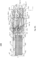
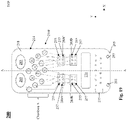
- Fig. 1 shows an example of a cartridge reader unit 100, used in system 300 (see Fig. 3 ) in accordance with an embodiment.
- the cartridge reader unit 100 may be configured to be compact and/or small enough to be a hand-held, mobile instrument, for example.
- the cartridge reader unit 100 includes a body or housing 110 that has a display 120 and a cartridge receiver 130 for receiving a cartridge assembly.
- the housing 110 may have an ergonomic design to allow greater comfort if the reader unit 100 is held in an operator's hand.
- the shape and design of the housing 110 is not intended to be limited, however.
- the cartridge reader unit 100 may include an interface 140 and a display 120 for prompting a user to input and/or connect the cartridge assembly 200 with the unit and/or sample, for example.
- the system 300 may process, detect, analyze, and generate a report of the results, e.g., regarding multiple detected biomarkers in a test sample, e.g., five cardiac biomarkers, using sensor (magnetoresistive) technology, and further display the biomarker results, as part of one process.
- the display 120 may be configured to display information to an operator or a user, for example.
- the display 120 may be provided in the form of an integrated display screen or touch screen (e.g., with haptics or tactile feedback), e.g., an LCD screen or LED screen or any other flat panel display, provided on the housing 110, and (optionally) provides an input surface that may be designed for acting as end user interface (UI) 140 that an operator may use to input commands and/or settings to the unit 100, e.g., via touching a finger to the display 120 itself.
- UI end user interface
- the size of the display 120 may vary.
- the display 120 may be configured to display a control panel with keys, buttons, menus, and/or keyboard functions thereon for inputting commands and/or settings for the system 300 as part of the end user interface.
- the control panel includes function keys, start and stop buttons, return or enter buttons, and settings buttons.
- the cartridge reader 100 may include, in an embodiment, any number of physical input devices, including, but not limited to, buttons and a keyboard.
- the cartridge reader 100 may be configured to receive input via another device, e.g., via a direct or wired connection (e.g., using a plug and cord to connect to a computer (PC or CPU) or a processor) or via wireless connection.
- display 120 may be to an integrated screen, or may be to an external display system, or may be to both.
- the test results e.g., from a cartridge reader 310, described with reference to Fig. 3 , for example
- the user interface 140 may be provided separate from the display 120.
- other input devices e.g., remote, keyboard, mouse, buttons, joystick, etc.
- the devices and/or methods used for input into the cartridge reader 100 are not intended to be limiting.
- All functions of the cartridge reader 100 and/or system 300 may, in one embodiment, be managed via the display 120 and/or input device(s), including, but not limited to: starting a method of processing (e.g., via a start button), selecting and/or altering settings for an assay and/or cartridge assembly 200, selecting and/or settings related to pneumatics, confirming any prompts for input, viewing steps in a method of processing a test sample, and/or viewing (e.g., via display 120 and/or user interface 140) test results and values calculated by the GMR sensor and control unit / cartridge reader.
- the display 120 may visually show information related to analyte detection in a sample.
- the display 120 may be configured to display generated test results from the control unit / cartridge reader.
- real-time feedback regarding test results that have been determined / processed by the cartridge reader unit / controller (by receiving measurements from the sensing device, the measurements being determined as a result of the detected analytes or biomarkers), may be displayed on the display 120.
- a speaker may also be provided as part of the cartridge reader unit 100 for providing an audio output. Any number of sounds may be output, including, but not limited to speech and/or alarms.
- the cartridge reader unit 100 may also or alternatively optionally include any number of connectors, e.g., a LAN connector and USB connector, and/or other input/output devices associated therewith.
- the LAN connector and/or USB connector may be used to connect input devices and/or output devices to the cartridge reader unit 100, including removable storage or a drive or another system.
- the cartridge receiver 130 may be an opening (such as shown in Fig. 1 ) within the housing 110 in which a cartridge assembly (e.g., cartridge assembly 200 of Fig. 2 ) may be inserted.
- the cartridge receiver 130 may include a tray that is configured to receive a cartridge assembly therein. Such a tray may move relative to the housing 110, e.g., out of and into an opening therein, and to thereby receive the cartridge assembly 200 and move the cartridge assembly into (and out of) the housing 110.
- the tray may be a spring-loaded tray that is configured to releasably lock with respect to the housing 110. Additional details associated with the cartridge reader unit 100 are described later with respect to Fig. 3 .
- cartridge assembly 200 may be designed for insertion into the cartridge reader unit 100, such that a sample (e.g., blood, urine) may be prepared, processed, and analyzed.
- Figs. 2A-2C illustrate an exemplary embodiment of a cartridge assembly 200 in accordance with embodiments herein. Some general features associated with the disclosed cartridge assembly 200 are described with reference to these figures. However, as described in greater detail later, several different types of cartridge cards and thus cartridge assemblies may be utilized with the cartridge reader unit 100 and thus provided as part of system 300.
- the sampling handling system or cartridge assembly 200 may take the form of disposable assemblies for conducting individual tests.
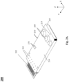
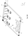
- FIG. 2A shows a top, angled view of a cartridge assembly 200, in accordance with an embodiment herein.
- the cartridge assembly 200 includes a sample processing card 210 and a sensing and communication substrate 202 (see also Fig. 2B ).
- the sample processing card 210 is configured to receive the sample (e.g., via a sample port such as injection port, also described below) and, once inserted into the cartridge reader unit 100, process the sample and direct flow of the sample to produce a prepared sample.
- Card 210 may also store waste from a sample and/or fluids used for preparing the test sample in an internal waste chamber(s) (not shown in Fig. 2A , but further described below).
- Memory chip 275 may be read and/or written to and is used to store information relative to the cartridge application, sensor calibration, and sample processing required, for example.
- the memory chip 275 is configured to store a pneumatic system protocol that includes steps and settings for selectively applying pressure to the card 210 of the cartridge assembly 200, and thus implementing a method for preparation of sample for delivery to a magnetoresistive or magnetoresistance sensor (e.g., GMR sensor chip 280).
- GMR sensor chip 280 magnetoresistive or magnetoresistance sensor
- the memory chip may be used to mistake-proof each cartridge assembly 200 inserted into the unit 100, as it includes the automation recipe for each assay.
- the memory chip 275 also contain traceability to the manufacturing of each card 210 and/or cartridge assembly 200.
- the sensing and communication substrate 202 may be configured to establish and maintain communication with the cartridge reader unit 100, as well as receive, process, and sense features of the prepared sample.
- the substrate 202 establishes communication with a controller in the cartridge reader unit 100 such that analyte(s) may be detected in a prepared sample.
- the sample processing card 210 and the sensing and communication substrate 202 are assembled or combined together to form the cartridge assembly 200.
- adhesive material see, e.g., Fig.
- the substrate 202 may be a laminated layer applied to the sample processing card 210.
- the substrate 202 may be designed as a flexible circuit that is laminated to sample processing card 210.
- the sample processing card 210 may be fabricated from a ceramic material, with the circuit, sensor (sensor chip 280) and fluid channels integrated thereon.
- the card 210 and substrate 202 may be mechanically aligned and connected together.
- a portion of the substrate 202 may extend from an edge or an end of the card 210, such as shown in Fig. 2A .
- the substrate 202 may be aligned and/or sized such that it has similar or smaller edges than the card 210.
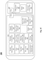
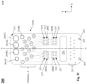
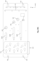
- Fig. 2C schematically illustrates features of the cartridge assembly 200, in accordance with an embodiment. As shown, some of the features may be provided on the sample processing card 210, while other may be associated with the substrate 202.
- the cartridge assembly 200 includes a sample injection port 215, which may be provided on a top of the card 210. Also optionally provided as part of the card 210 are filter 220 (also referred to herein as a filtration membrane), vent port 225, valve array 230 (or valve array zone 230), and pneumatic control ports 235.
- Communication channels 233 are provided within the card 210 to fluidly connect such features of the card 210.
- Pneumatic control ports 235 are part of a pneumatic interface on the cartridge assembly 200 for selectively applying pressurized fluid (air) to the communication channels 233 of the card, for directing flow of fluids (air, liquids, test sample, etc.) therein and/or valve array 230.
- the card 210 may include distinct valve control ports 535 connected to designated communication channels 233 for controlling the valves in the valve array 230.
- the card 210 may also have one or more metering chambers 240, gas permeable membranes 245, and mixing channels 250 that are fluidly connected via communication channels 233. Metering chamber(s) are designed to receive at least the test sample (either directly or filtered) therein via communication channels 233. Such features are discussed in greater detail below with reference to Figs.
- a sample may be injected into the cartridge assembly 200 through port 215 and processed by means of filtering with filter (e.g., filter 220), metering in metering chamber(s) 240, mixing in mixing channel(s) 250, heating and/or cooling (optional), and directing and changing the flow rate via communication channels 233, pneumatic control ports 235, and valve array 230.
- filter e.g., filter 220
- metering in metering chamber(s) 240 metering in metering chamber(s) 240
- mixing channel(s) 250 e.g., heating and/or cooling (optional)
- directing and changing the flow rate via communication channels 233, pneumatic control ports 235, and valve array 230.
- flow of the fluid may be controlled using internal micro fluidic channels (also generally referred to as communication channels 233 throughout this disclosure) and valves via a connection of a pneumatic system (e.g., system 330 in the cartridge reader unit 100, as shown in Fig.
- a pneumatic interface e.g., on the card 210 that has pneumatic control ports 235 or a similar connection section.
- Optional heating of the test sample and/or mixing materials / fluids within the card 210 may be implemented, in accordance with an embodiment, via a heater 259 which may be in the form of a wire trace provided on a top side of a PCB / substrate 202 with a thermistor.
- Optional cooling of the test sample and/or mixing materials / fluids within the card 210 may be implemented, in accordance with an embodiment, via a TEC module integrated in the cartridge assembly 200 (e.g., on the substrate 202), or, in another embodiment, via a module integrated inside of the cartridge reader unit 100.
- Processing may also optionally include introduction of reagents via optional reagent sections 260 (and/or blister packs) on the card 210 and/or via reagent cartridges in the housing 110 the cartridge reader unit 100. Reagents may be released or mixed as required by the process for that sample and the cartridge assembly 200 being analyzed.
- optional blister packs 265 may be provided on the card 210 to introduce materials such as reagents, eluants, wash buffers, magnetic nano particles, bead solution, or other buffers to the sample via communication channels 233 during processing.
- One or more internal waste chambers (also referred to herein as waste tanks for waste reservoirs) 270 may also be optionally provided on the card 210 to store waste from the sample and reagents.
- An output port 255 - also referred to as a sensor delivery port, or input port to the sensor - is provided to output a prepared sample from the card 210 to a GMR sensor chip 280, as discussed below, for detecting analytes in the test sample.
- the output port 255 may be fluidly connected to a metering chamber for delivering the test sample and one or more mixing materials to the sensor. Accordingly, the sensor may be configured to receive the test sample and the one or more mixing materials via the at least one output port 255.
- an input port 257 - also referred to as a waste delivery port, or output port from the sensor - is provided to output any fluid or sample from the GMR sensor chip 280 to a waste chamber 270.
- Waste chamber(s) 270 may be fluidly connected to other features of the card 210 (including, for example, metering chamber(s) 240, an input port 257, or both) via communication channels 233.
- the cartridge assembly 200 has the ability to store, read, and/or write data on a memory chip 275, which may be associated with the card 210 or the substrate 202.
- the memory chip 275 may be used to store information related and/or relative to the cartridge application, sensor calibration, and required sample processing (within the sample processing card), as well as receive additional information based on a prepared and processed sample.
- the memory chip 275 may be positioned on the sample processing card 210 or on the substrate 200.
- a magnetoresistive sensor may be utilized, in accordance with embodiments herein, to determine analytes (such as biomarkers) within a test sample using the herein disclosed system. While the description and Figures note use of a particular type of magnetoresistance sensor, i.e., a giant magnetoresistance (GMR) sensor, it should be understood that this disclosure is not limited to a GMR sensor platform.
- the sensor may be an anisotropic magnetoresistive (AMR) sensor and/or magnetic tunnel junction (MTJ) sensors, for example.
- AMR anisotropic magnetoresistive
- MTJ magnetic tunnel junction
- other types of magnetoresistive sensor technologies may be utilized. Nonetheless, for explanatory purposes only, the description and Figures reference use of a GMR sensor as a magnetoresistive sensor.
- the substrate 202 of cartridge assembly 200 may be or include an electronic interface and/or a circuit interface such as a PCB (printed circuit board) that may have a giant magnetoresistance (GMR) sensor chip 280 and electrical contact pads 290 (or electrical contact portions) associated therewith. Other components may also be provided on the substrate 202.
- the GMR sensor chip 280 is attached at least to the substrate 202, in accordance with an embodiment.
- the GMR sensor chip 280 may be placed on and attached to the substrate 202 using adhesive, for example.
- a liquid adhesive or a tape adhesive may be used between the GMR sensor 280 and the PCB substrate 202.
- Such a design may require a bond to the PCB at the bottom and a bond to the processing card at the top, for example.
- GMR sensor chip 280 attaches to the substrate 202 to the substrate 202 to the substrate 202
- approaches for attaching the GMR sensor chip 280 to the substrate 202 include, but are not limited to: friction fitting the GMR sensor to the PCB, and connecting a top of the GMR sensor chip 280 directly to the sample processing card 210 (e.g., in particular when the substrate 202 is provided in the form of a flexible circuit that is laminated (to the back) of sample processing card 210.
- the GMR sensor chip 280 may be designed to receive a prepared sample from the output port 255 of the sample processing card 210. Accordingly, placement of the GMR sensor chip 280 on the substrate may be changed or altered based on a position of the output port 255 on card 210 (thus, the illustration shown in Fig.
- the GMR sensor chip 280 is positioned on a first side of the substrate 202 (e.g., a top side that faces an underside of the card 210, as shown in Fig. 2B ), e.g., so as to receive the prepared sample from an output port that outputs on an underside of the card 210, and the contact pads 290 are positioned on an opposite, second side of the substrate (e.g., on a bottom side or underside of the substrate 202, such that the contact pads 290 are exposed on a bottom side of the cartridge assembly 200 when fully assembled for insertion into the cartridge reader unit 100).
- a first side of the substrate 202 e.g., a top side that faces an underside of the card 210, as shown in Fig. 2B
- the contact pads 290 are positioned on an opposite, second side of the substrate (e.g., on a bottom side or underside of the substrate 202, such that the contact pads 290 are exposed on a bottom side of the cartridge assembly 200 when fully assembled for
- the GMR sensor chip 280 may include its own associated contact pads (e.g., metal strips or pins) that are electrically connected via electronic connections on the PCB/substrate 202 to the electrical contact pads 290 provided on the underside thereof. Accordingly, when the cartridge assembly 200 is inserted into the cartridge reader 100, the electrical contact pads 290 are configured to act as an electronic interface and establish an electrical connection and thus electrically connect with electronics (e.g., cartridge reader 310) in the cartridge reader unit 100. Thus, any sensors in the sensor chip 280 are connected to the electronics in the cartridge reader unit 100 through the electrical contact pads 290 and contact pads of the GMR sensor chip 280.
- any sensors in the sensor chip 280 are connected to the electronics in the cartridge reader unit 100 through the electrical contact pads 290 and contact pads of the GMR sensor chip 280.
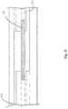
- Figs. 2D and 2E show views of an exemplary cross section of a mating or connection interface of card 210 and substrate 202. More specifically, Fig. 2D illustrates an interface, in accordance with one embodiment, between an output port 255 on the card 210 and GMR sensor chip 280 of the substrate 202.
- a PCB substrate 202 positioned below and adjacent to a card 210 according to any of the herein disclosed embodiments. The substrate 202 may be attached to bottom surface (222) of the card 210.
- the card 210 has a channel feature, labeled here as microfluidic channel 433 (which is one of many communication channels within the card 210), in at least one layer thereof, designed to direct a test sample that is processed within the card 210 to an output port 255 directed to GMR sensor 280.
- adhesive material may be provided between layers of the card 210, e.g., adhesive 434A may be provided between a layer in the card that has reagent ports 434B and a layer with the channel 433.
- the substrate 202 includes a GMR sensor chip 280 that is positioned adjacent to the channel 433 and output port 255 of the card 210.
- FIG. 2E shows a schematic drawing related to analyte detection using a card 210 with said one or more microfluidic channels 433 and GMR sensor chip 280 associated with a silicon wafer of a PCB substrate 202 .
- the analyte detection is made possible through micro fluidics, surface chemistry, sample targets, nano magnetic beads, magnetic field and giant magneto resistance (GMR) sensor chip 280.
- Micro fluidic channel(s) 433 i.e., communication channels
- in the card 210 may assist in directing flow of a separated test sample and nano magnetic beads from a magnetic bead-bound entity 1415 for processing, for example.
- Magnetic bead-bound entity 1415 may be configured to interact with biomolecule 1425 (also referred to as a target) or an analyte of interest, such as in a sandwich complex of antibody-analyte-magnetic bead-bound antibody.
- Sample targets are the items to be detected and measured.
- Nano magnetic beads 1415 bond to sample targets 1425.
- an insulating material 1445, 1455 may be provided between over the sensor(s) 280.
- insulating layer 1455 may be in direct contact with GMR sensor(s) 280 and may comprise, for example, a metal oxide layer.
- Biosurface layer 1445 may be in direct contact with insulating layer 1455, in accordance with one embodiment.
- Substrate 202 may serve as a scaffold for each component above it, e.g., the GMR sensors 280, insulating layer 1455, and/or biosurface layer 1445.
- substrate 202 may be made from a silicon wafer or a laminated flex layer.
- Magnetic field (from a magnetic field generator 365 that is different than magnetic field generator 360, described below with reference to Fig. 3 ) may be used to excite the nano magnetic particles located near sensors.
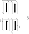
- Fig. 2F shows a schematic example of antiparallel and parallel magnetization, for example. Similar principles may be applied here at the GMR sensor chip 280.
- the GMR sensor may be designed to include of a metallic multi-layered structure with a non-magnetic conductive interlayer 890 sandwiched between two magnetic layers 880A and 880B.
- the non-magnetic conductive interlayer 890 may be a thin copper film.
- GMR sensor chip 280 is constructed using a metallic structure with several nanometers non-magnetic conducting thin film (e.g., copper) sandwiched between two ferromagnetic layers (880A and 880B in Fig. 2F ) changes depending on the relative magnetization direction of the ferromagnetic layers.
- the electrical resistance of the metallic multi-layered structure changes depending on the relative magnetization direction of the magnetic layers 880A and 880B. Parallel magnetization (as shown in the right half of Fig. 2F ) results in lower resistance, while anti-parallel magnetization (as shown in the left half of Fig. 2F ) results in higher resistance. This phenomenon facilitates detection of stray fields from magnetic materials at nanometer scales.
- the magnetization direction may be controlled by a magnetic field applied externally. As a result, the metallic multi-layered structure displays a change in its electrical resistance as a function of the external magnetic field.
- GMR sensors have sensitivities that exceed those of anisotropic magnetoresistance (AMR) or Hall sensors. This characteristic enables detection of stray fields from magnetic materials at nanometer scales. For example, stray fields from magnetic nanoparticles that bound on sensor surface will alter the magnetization in the magnetic layers, and thus change the resistance of the GMR sensor. Accordingly, changes in the number of magnetic nanoparticles bound to the GMR sensor per unit area can be reflected in changes of the resistance value of the GMR sensor.
- AMR anisotropic magnetoresistance
- the senor utilized in cartridge assembly 200 is a GMR sensor chip 280.
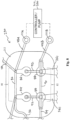
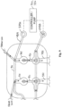
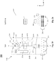
- FIG. 3 additional features of the cartridge reader unit 100 are schematically shown to further describe how the cartridge reader unit 100 and cartridge assembly 200 are configured to work together to provide the system 300 for detecting analyte(s) in a sample.
- the cartridge assembly 200 may be inserted into the housing 110 of the cartridge reader unit 100.
- the housing 110 of the cartridge reader unit 100 may further include or contain a processor or control unit 310, also called a “controller” and/or a “cartridge reader” 310 herethroughout, a power source 320, a pneumatic system 330, a communications unit 340, a (optional) diagnostic unit 350, a magnetic field generator 360, and a memory 370 (or data storage), along with its user interface 140 and/or display 120.
- a reagent opener (not shown in Fig.
- reagent source on an inserted cartridge assembly e.g., for opening a reagent source on an inserted cartridge assembly or for introducing reagent into the cartridge assembly (e.g., if the reagent is not contained in the assembly in a particular reagent section), may also be provided as part of the cartridge reader unit 100.
- the cartridge memory chip 275 may be read from the cartridge assembly 200 (e.g., read by cartridge reader 310 / control unit, or PCB assembly, in the unit 100) to determine the pneumatic system protocol that includes steps and settings for selectively applying pressure to the card 210 of the cartridge assembly 200, and thus implementing a method for preparation of sample for delivery to a sensor (e.g., GMR sensor chip 280), and thus the sample placed in the assembly 200 may be prepped, processed, and analyzed.
- the control unit or cartridge reader 310 may control inputs and outputs required for automation of the process for detecting the analyte(s) in a sample.
- the cartridge reader 310 may be a real-time controller that is configured to control, among other things, the giant magnetic resistance (GMR) sensor chip 280 and/or memory chip 275 associated with the cartridge assembly 200 and the pneumatic system 330 within the housing 110, as well as the controls from user interface, driving the magnetic field generator 360, and receiving and/or sending signals from/to sensor chip and/or memory associated with the cartridge assembly 200, for example.
- the cartridge reader 310 is provided in the form of a PCB (printed circuit board) which may include additional chips, memory, devices, therein.
- the cartridge reader 310 may be configured to communicate with and/or control an internal memory unit, a system operation initializer, a signal preparing unit, a signal preparing unit, a signal processing unit, and/or data storage (none of which are shown in the Figures), for example.
- the cartridge reader 310 may also be configured to send and receive signals with respect to the communications unit 340 such that network connectivity and telemetry (e.g., with a cloud server) may be established, and non-volatile recipes may be implemented, for example.
- the communications unit 340 allows the cartridge reader unit 100 to transmit and receive data using wireless or wired technology.
- Power can be supplied to the cartridge reader unit 100 via power source 320 in the form of an internal battery or in the form of a connector that receives power via an external source that is connected thereto (e.g., via a cord and a plug).
- Power source 320 is configured to supply power to parts of the cartridge reader unit 100, when activated and/or when a cartridge assembly 200 is mated with the unit 100.
- power source 320 may supply power to the control unit and PCB assembly 560 of cartridge reader 310, magnetic field generator 360, display 120 and/or user interface 140, and pneumatic system 330 (including, for example, any motors, valves, and/or pumps associated therewith).
- Power source 320 may be at least one internally mounted battery pack 320, in accordance with an embodiment herein.
- the pneumatic system 330 is used to process and prepare a sample (e.g., blood, urine) placed into the cartridge assembly 200 by means of moving and directing fluids inside and along the sample processing card 210 (e.g., via pneumatic connection 235, through its channels and connecting to direct elastomeric valves).
- the pneumatic system 330 may be a system and/or device for moving fluid, which could use, for example, plungers and/or pistons in contact with fluids.
- the magnetic field generator 360 may be an external magnetic coil or other field generating device that is mounted in the unit 100 or integrated in some fashion with one or more of the chips (e.g., sensor chip 280) provided on the cartridge assembly 200 or provided on the circuit board of the cartridge reader unit 100.
- the magnetic field generator 360 is used to stimulate magnetic nanoparticles near the GMR sensor chip 280 while reading the signal.
- a second magnetic field generator 365 which may be a coil or other field generating device, may be provided as part of the cartridge reader unit 100 and in the housing 110.
- the second magnetic field generator 365 may be separate and distinct from magnetic field generator 360.
- This second magnetic field generator 365 may be configured to generate a non uniform magnetic field such that it may apply such a magnetic field to a part (e.g., top, bottom, sides) of the sample processing card 210 of an assembly 200 during preparation and processing of a sample, e.g., when moving mixing material(s), such as a buffer and/or magnetic beads from a mixing material source, and test sample within the card.
- the second magnetic field generator 365 is provided on an opposite end or side of the cartridge reader unit (e.g., located in a top of the housing 110 of unit 100), i.e. away from the magnetic field generator 360, which is used for GMR sensing.
- the second magnetic field generator 365 is provided on an opposite end of the cartridge reader unit as compared to the magnetic field generator 360 (e.g., second magnetic field generator is located in a top of the housing 110 of unit 100 and magnetic field generator 360 is provided at a bottom end of the unit 100 (e.g., near cartridge receiver 130)).
- the total magnetic field for sensing biomarkers / analytes includes an applied field from magnetic field generator 360 (either external or integrated with the sensor chip) along with any disturbance from magnetic nanoparticles near the GMR sensor chip 280.
- the reagent opener is optionally used to introduce reagents during the sample processing and reading of the GMR sensor chip 280 (e.g., if the reagent is not contained in the card in a particular reagent section).
- the user interface / display 120 allows an operator to input information, control the process, provide system feedback, and display (via an output display screen, which may be a touch screen) the test results.
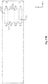
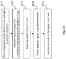
- Fig. 4 shows general steps of a method 400 for performing analyte detection in a sample using the herein disclosed system 300.
- the system is initialized.
- initialization of the system may include: applying power to the system 300 (including cartridge reader unit 100), determining configuration information for the system, reading computations, determining that features (e.g., magnetic field generator and carrier signals) are online and ready, etc.
- a whole test sample is added or loaded into the cartridge assembly 200 (e.g., sample is injected into the injection port 215, as shown in Fig. 2C ).
- the order of steps 410 and 415 may be changed; i.e., the addition of the whole test sample to the assembly 200 may be before or after the system is initialized.
- the cartridge assembly 200 is inserted into the cartridge reader unit 100.
- user instruction may be input to the cartridge reader unit 100 and/or system 300 via the user interface / display 120.
- the processing of sample is initiated via the control unit 310.
- This initiation may include, for example, receiving input via an operator or user through the user interface/display 120 and/or a system that is connected to the reader unit 100.
- processing may be initiated automatically via insertion of the cartridge assembly 200 into the cartridge reader unit 100 and detecting presence of the cartridge assembly 200 therein (e.g., via electrical connection between electrical contact pads 290 on the assembly 200 with the control unit 310, and automatically reading instructions from memory chip 275).
- the sample is processed at step 425 using pneumatic control instructions (e.g., obtained from memory chip 275) in order to produce a prepared sample.
- pneumatic control instructions e.g., obtained from memory chip 275
- the processing of the sample may be dependent upon the type of sample and/or the type of cartridge assembly 200 inserted into the reader unit 100. In some cases, the processing may include a number of steps, including mixing, introduction of buffers or reagents, etc., before the sample is prepared.
- the prepared sample is sent (e.g., through channels in the card 210 and to output port 255, via pneumatic control through pneumatic system 330 and control unit 310) to the GMR sensor chip 280.
- analytes in the prepared sample are detected at the GMR sensor chip 280.
- test results may be displayed at 450, e.g., via the display 120 / user interface.
- test results are saved.
- any fluids or sample may be directed from the GMR sensor chip 280 through an input port 257 to waste chamber 270.
- the cartridge assembly 200 may be ejected from the cartridge reader unit 100. In accordance with an embodiment, this may be automatically performed, e.g., mechanics within the housing 110 of the cartridge reader unit 100 may push the assembly 200 out of the housing 110, or performed manually (by way of a button or force) by the operator, for example.
- system 300 described herein may utilize a pneumatic control system as disclosed in International Patent App. No. PCT/US2019/__, entitled “SYSTEM AND METHOD FOR GMR-BASED DETECTION OF BIOMARKERS” (Attorney Docket No. 026462-0504846) and filed on the same day, which is hereby incorporated by reference herein in its entirety.
- the system 300 described herein may sense analytes as disclosed in International Patent App. No. PCT/US2019/__, entitled “SYSTEM AND METHOD FOR SENSING ANALYTES IN GMR-BASED DETECTION OF BIOMARKERS” (Attorney Docket No. 026462-0504848) and filed on the same day, which is hereby incorporated by reference herein in its entirety.
- the sensing device, or GMR sensor chip 280 may include one or more microfluidic channels and a plurality of sensor pads disposed within the one or more microfluidic channels as disclosed in the -0504848 application.
- such a channel may optionally include a plurality of GMR sensors disposed within a channel.
- GMR sensors may be all identically configured to detect a single analyte, the redundancy allowing for enhanced detection.
- GMR sensors may also be all configured differently to detect a myriad of analytes or a combination of differently configured sensors with some redundancies.
- the configuration of the channel is not limiting.
- the GMR sensors in the channel may be designed to provide the output (test results) from the GMR sensor chip 280.
- Figs. 28-31 generally illustrate functional blocks of the cartridge reader 310 (control unit) and a signal processor within the cartridge reader unit 100, and processes associated therewith, that may be utilized and implemented by the cartridge reader unit 100 with regards to an inserted cartridge assembly 200.
- the system 300 described herein may process signals at the GMR sensor as disclosed in International Patent App. No. PCT/US2019/__, entitled “SYSTEM AND METHOD FOR PROCESSING ANALYTE SIGNALS IN GMR-BASED DETECTION OF BIOMARKERS (Attorney Docket No. 026462-0504850) and filed on the same day, which is hereby incorporated by reference herein in its entirety.
- cartridge reader 310 is configured to perform the function of processing results from the GMR sensor chip 280 using a sample preparation control part having a memory reader unit and a sample preparation control unit (e.g., used to receive signals indicating that a cartridge assembly 200 has been inserted into the cartridge reader unit 100, read information stored in the memory chip 275, and generate pneumatic control signals and send them to the pneumatic system 330) and a signal processing part adapted to control electrical elements, prepare and collect signals, and process, display, store, and/or relay detection results to external systems, including processing measurements signals to obtain test results of the analyte detection, as described in detail in the -0504850 application. Additional features relating to the cartridge reader 310 and signal processor of the unit 100 are provided in greater detail later in this disclosure.
- FIGs. 1 and 2A-2F the features shown are representative schematics of a cartridge reader unit 100 and cartridge assembly 200 that are part of the herein disclosed system 300 for detecting the analyte(s) in a sample. Accordingly, the illustrations are explanatory only and not intended to be limiting.
- the arrangement, placement, inclusion, and number of features provided on a sample processing card 210 in the cartridge assembly 200 may be based on the test sample being analyzed and/or the test being performed (e.g., detection of biomarkers, detection of metal, etc.), for example.
- the card 210 may be arranged, in some embodiments, such that there are zones on the card, and/or such that features are provided in different layers (however, such layers do not need to be distinct layers with a body thereof; rather, layered relative to one another at a depth or height (in the Z-direction)).
- the sample processing card 210 may be formed using parts that are laser cut to form inlets, channels, valve areas, etc. and sandwiched and connected / sealed together.
- one or more layers of the sample processing card may be laser cut, laminated, molded, etc. or formed from a combination of processes.
- the method of forming the sample processing card 210 is not intended to be limiting.
- some of the Figures include a depiction of layers to show positioning of parts of the sample processing card 210 relative to one another (e.g., positioning within the card relative to other features that are.placed above and/or below). Such illustrations are provided to show exemplary depths or placement of the features (channels, valves, etc.) within a body of the sample processing card 210, without being limiting.
- each card 210 has body 214 extending in a longitudinal direction along a longitudinal centerline A-A (provided in the Y-direction) when viewed overhead or from the top.
- each card 210 may have dimensions defined by a length extending in the longitudinal direction (i.e., along or relative to centerline A-A), a width extend laterally to the length (e.g., in the X-direction), and a height (or depth or thickness) in the Z-direction, or vertical direction.
- the body 214 of the card 210 may be of a substantially rectangular configuration.
- the cartridge receiver 130 (and/or any related tray) in the cartridge reader unit 100 is sized to accommodate the dimensions of the sample processing card 210, such that the card 210 may be inserted into the housing of the unit 100.
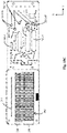
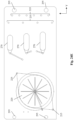
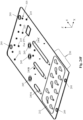
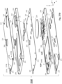
- Figs. 5-13 may be referenced to help illustrate features of an exemplary sample processing card 210.
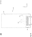
- Fig. 5 is an example of a sample processing card 210A configured for use as a sample processing card in the cartridge assembly 200, in accordance with an embodiment therein, and that Figs. 6-13 are illustrative only, and none of these embodiments are intended to be limiting.
- a sample processing card 210 may include a sample injection area, a valve array zone 230, a mixing zone, a pneumatic control interface (also referred to herein as a pump interface or pneumatic interface) and a control and delivery zone (to sensor chip 280). Any of these areas and/or zones may be positioned relative to one another and/or overlap one another (e.g., in different layers of the card).
- the sample injection area is an area on the card for injecting the whole test sample.
- Valve array zone 230 includes a number and/or a series of valves therein that are controlled by the pneumatic system 330 in the cartridge reader unit 100 for directing and/or mixing fluids within the card 210.
- the valves in this zone 230 may be connected to communication channels within the sample processing card 210.
- Mixing zone refers to areas used to mix the separated test sample with and/or move other fluids (e.g., reagents, wash buffers, magnetic beads).
- the valves (e.g., with elastomeric deflection portions) in the valve array zone 230 may be selectively controlled between open and closed positions to allow for selective delivery through communication channels, e.g., delivery of the test sample to fluid metering chamber(s) 240 that may be provided in the mixing zone, for mixing with reagents, buffers, etc., for example.
- Control and delivery zone may be an area on the card 210 that communicates with the cartridge reader 310 of the unit 100 as well as the pneumatic system 330 thereof.
- a number of ports 235 (at least one pneumatic control port 235) for controlling movement of the fluids within channels of the card 210 are provided in the pneumatic control interface.
- the control and delivery zone may also optional include ports for controlling the positions of the valves in the valve array zone 230.
- Each pneumatic control port 235 has a corresponding communication channel fluidly connected thereto for connection with other features (e.g., metering chamber) within the card 210.
- a sample processing card 210 may include a sample injection port 215, which may be provided on the card 210, for receiving the test sample within a body of the card.
- the injection port 215 is configured to receive a whole test sample, e.g., whole blood, urine, etc., in accordance with some embodiments herein.
- the test sample may be pre-separated (e.g., serum from blood) before injecting into the injection port 215.
- the injection port 215 may include a small opening with a receiving hole provided in the top surface 218 of the card 210 that extends vertically (downwardly, in the Z-direction) at a depth into the card 210 and optionally through to the filtration membrane, e.g., filter 220.
- the filtration membrane 220 may be provided between or sandwiched at a depth between the top surface 218 and bottom surface 222 of the sample processing card 210, in accordance with embodiments.
- the filtration membrane 220 of sample processing card 210A is depicted as being generally circular; however, the area or shape of the membrane 220 is not intended to be limited.
- the filtration membrane 220 is formed from a material configured to receive an injected whole test sample and separate a test sample (for further preparation, e.g., with reagents, buffers, magnetic beads) from that sample.
- the filter membrane 220 may be a blood filtration membrane, e.g., to separate a plasma sample from whole blood.
- the filtration membrane 220 may be formed from an asymmetric filter material, for example. Such a material may have an increasing smaller pore size on its underside.
- the membrane 220 may be used to remove red blood cells and other large biological materials from the patient test sample injected into the injection port 215, and provide plasma for further processing in the sample processing card 210.
- the filter may be provided in the form of a glass fiber membrane 220A.
- glass fiber membrane 220A may be used for nucleic acid extraction (whereas filter membrane 220 is used to filter plasma from whole blood), in accordance with an embodiment. While generally filter 220 may be used throughout the description, it should be understood that reference to filter or filter membrane 220 and its features may also refer and apply to glass fiber membrane 220A, in this disclosure.
- filter 220 may be optional within the card 210 and cartridge assembly 200.
- the test sample may be separated by a user or operator outside of the cartridge assembly 200.
- a user may first separate serum or plasma therefrom, i.e., outside of the assembly 200. Accordingly, use of a filter in the assembly 200 may not be required.
- the test sample (e.g., whole blood) may be loaded, introduced, or injected (e.g., using a pipette or needle) into the small opening of injection port 215.
- the sample may then be configured to spread laterally through and across the filtration membrane 220 to purify and/or separate components of the sample (e.g., in the case of an injected whole blood sample, the filter 220 will filter the blood to yield plasma).
- the separated test sample e.g., plasma
- This receiving area 224 may be provided adjacent to or below (in the vertical direction, i.e., direction of depth or height; in the Z-direction) the filtration membrane 220, for example.
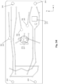
- the loaded or injected sample will wick across the filtration membrane 220 - as represented in some Figures by the lines therein - e.g., up and/or diagonally to a side opposite the injection port 215, where the vent port 225 may be positioned or provided.
- Vent port 225 is an opening in the sample processing card 210 that extends vertically at a depth between the area of the filtration membrane 220 and the top surface 218 of the sample processing card 210. In an embodiment, the depth of the vent port 225 extends from the receiving area 224 (e.g., top or bottom of the area 224, or sample chamber) to the top surface 218. Vent port 225 is open to the atmosphere and configured to vent air from the card. Vent port 225 may be similar in size to the opening of injection port 215, in accordance with an embodiment. The vent port 225 extends down into same plane as the membrane 220, in one embodiment.
- vent port 225 allows pressure to be vented or released from inside the sample processing card (e.g., from the membrane 220 and/or receiving area 224, or other connected channels therein) and out to the atmosphere; e.g., as a blood test sample is injected and wicked in the membrane 220, it separates the plasma and any air in this area is pushed out through vent port 225.
- vent port 225 may be positioned relatively opposite (e.g., 180 degrees) to the injection port 215.
- the vent port 26 is shown on an upper, left side near the membrane 220.
- vent port 225 and injection port 215 may be positioned closer together, or on a same side of the sample processing card.
- a channel, guide, or other portion may be provided in a layer of the sample processing card that routes the channels around the membrane 220, for example.
- the location of the injection port 215 and vent port 225 may be switched or rotated to another location around or relative to the filtration membrane 220.
- the injection port 215 and vent port 225 locations may be switched.
- the ports 215, 225 may be positioned along another line, e.g., a vertical line, a horizontal line, or angled line, across/through and relative to the membrane 220. Accordingly, the illustrated locations of the ports 215, 225 is not meant to be limiting.
- sample processing card 210 may include one or more air vents (or air ports) therein that may be used to vent and/or pull air therethrough.
- vent port 225 may act as the air vent, while in other embodiments, air vent may be a separate port.
- the air vent and/or vent port 225 may be configured to allow air flow to dry the contained fiber membrane (e.g., a glass fiber membrane).
- the air vent may be normally closed via a valve, whose position (open or closed) may be controlled by the pneumatic system 330 (e.g., via connection to a designated port 235 and communication channel(s)).
- the separated test sample within receiving area 224 / sample chamber is designed for use and, optionally, mixing with a reagent, buffer, magnetic beads, etc. More specifically, the separated test sample is configured to be moved within the card 210 to prepare the test sample and then direct it to a GMR sensor chip 280 for sensing and outputting results to a user/operator.
- Fluid communication channels may fluidly connect the injection port 215 and receiving area 224 to a mixing material source and/or metering chamber(s), and/or other features within the card 210, as described in greater detail below.
- the card 210A may be configured to have features that are similar on either side (left and right) of a longitudinal centerline A-A (provided in the Y-direction) when viewed overhead (see Fig. 5 ), and thus are mirror images of each other. Accordingly, the sample processing card 210A of Fig. 5 provides assay areas that are split and arranged in a parallel manner, allowing multiple assays at one time. In Fig. 5 , similar reference numbers are used to represent features provided on both sides (i.e., left and right) of the sample processing card 210.
- sample processing card 210A of Fig. 5 allows for better mixing of the test sample (e.g., plasma) and reagent, buffer, magnetic beads, etc., along with use of control mechanisms (from unit 100), thereby resulting in better functioning of the card and thus higher assay specificity.
- test sample e.g., plasma
- reagent e.g., buffer, magnetic beads, etc.
- control mechanisms from unit 100
- some of the mechanisms used to control fluid mobility and mixing of the separated test sample in the sample processing card 210 are a series of valves provided in the valve array zone 230 as well as pneumatic control ports 235 in the pneumatic control interface.
- plasma that is separated from a blood sample using the filtration membrane 220 in the receiving area 224 may travel through a sample delivery channel that extends from the receiving area 224 (in this case, from a center, bottom portion thereof) via controlling such valves and ports using a controller and/or pump(s) of pneumatic system 300 that may be connected to the sample processing card 210 and cartridge assembly 200, in accordance with one embodiment.
- any of the embodiments of the sample processing card 210 may be configured to be positioned as part of the cartridge assembly 200 such that pneumatic control ports 235 of the pneumatic control interface are provided at an end of the card 210 that is first placed into the cartridge receiver 130 of the cartridge receiver unit 100. More specifically, while the Figures may generally depict ports 235 (or their interface) a bottom end or area of the card 210 when viewed longitudinally (e.g., with injection port 215 near a top of the card and ports 235 near a bottom), this bottom end of the card 210 with the pneumatic control ports 235 may actually be referred to herein as a "front end" or an "insertion end", when referring to insertion of the cartridge assembly 200 into unit 100.
- sample delivery channels may be provided in the sample processing card 210.
- two or more sample delivery channels may extend from the receiving area 224 to another features within the card (e.g., metering chambers 240).
- a series of valves may be provided in the valve array zone 230, in accordance with an embodiment.
- a first set of valves is provided in the housing and includes a first valve and a second valve that are each configured for movement between an open position and a closed position.
- a second set of valves is also provided in the housing, each valve being configured for movement between an open position and a closed position.
- Valves may be separated and may be provided on either side of the longitudinal centerline A-A of the card, in an embodiment.
- the valves may be separated into rows, e.g., a row of first valves extending parallel to a row of second valves. The row of first valves may be positioned longitudinally above the row of second valves, for example.
- valves and valve array zone 230 may be provided adjacent to or relatively longitudinally below the filtration membrane 220 (relative to and along the centerline) within the card 210.
- a series of valves may be provided in the valve array zone 230 relatively below the filtration membrane 220 in the vertical (Z) direction.
- the valves may be provided on the same side of a longitudinal axis or centerline A-A of the housing.
- valves may be provided in the valve array zone 230 relatively above the filtration membrane 220 in the vertical (Z) direction.
- valve array 230 with respect to the filter 220 along the card (longitudinally) and/or within the layers of the card is not critical for the micro fluidic communication channels, as the fluid may be routed any number of places (vertically and/or longitudinally) on the card 210 via the channels therein.
- each valve array zone 230 may include, or be formed from, an elastomeric material 212.
- the location of the elastomeric material 212 is represented by generally rounded rectangle section, which may be provided below the top surface 218 and at a depth within the sample processing card 210, for example.
- An example of the positioning of the elastomeric material 212 at a depth or in an intermediate layer of the card 210 is shown in greater detail in Fig. 6 and Fig. 7 .
- the elastomeric material 212 may be placed within a body of the sample processing card 210 such that valves that are formed in layers or within the body of the card.
- the elastomeric material 212 may include pockets and/or elastomeric deflection portions (as shown in Figs. 6-7 ) that are/act as the valves, which are aligned with interior channels within the card. Movement of the deflection portions via positive pressure (e.g., pressurized air or vacuum from pneumatic system 330) between open and closed positions allows fluid (plasma, reagent) to move within the channels and housing parts, as described below.
- positive pressure e.g., pressurized air or vacuum from pneumatic system 330
- valves i.e., elastomeric deflection portions
- the valves in the valve array zone 230 may be selectively controlled to allow for selective delivery of the separated test sample from the whole sample and/or a reagent, wash buffer, beads, etc. for mixing with the plasma to fluid metering chamber(s) 240, for example.
- controller(s) and/or pump(s) of pneumatic system 300 may be activated to control a position of the valves in the elastomeric materials 212 / zone 230 and/or to apply positive and/or negative pressure (suction or vacuum) to the sample processing card 210 such that, depending on the positioning of the valves, the fluids (plasma and/or reagent) move within and throughout channels provided in the sample processing card 210.
- the sample delivery channel may connect to any number of branch portions, which may channels that branch to a particular metering chamber 240. In one embodiment, two or more branch portions are provided. In an embodiment, such as shown in Fig. 5 , branch portions may extend to one or more of the valve array zones 230 (on either side of the centerline A-A), for example. Also connected to valve array zones 230 in Fig. 5 , via delivery channels, are reagent sections 260. The reagent sections 260 may be designed to receive a reagent therein.
- these sections 260 are provided in the housing of the sample processing card 210 in the form of substantially rounded or circular well that receives and contains a volume of reagent therein.
- the reagent may be in the form of a liquid, fluid, or solution, that is metered from each of the sections 260 through delivery channels via activating valves/controllers, such that it is combined with the separated plasma from the blood sample, described later below.
- a volume of reagent may be injected into (via a user or the cartridge reader unit 100), pre-loaded, or stored in the reagent sections 260 in the sample processing card 210.
- the reagent may be stored in the sections 260 of the sample processing card 210 using a blister pack configuration, i.e., the reagent is contained in the card and a seal is broken when testing of a sample takes place.
- the reagent may be injected into the sections 260 and temporarily stored in the well/section until the valves/controllers are activated.
- optional blister packs 265, wells, and/or storage chambers 285 may be provided on the card 210 to introduce materials such as reagents, wash buffers, magnetic nano particles, bead solution, or other buffers to the separated test sample during processing.
- Such blister packs 265 and/or storage chambers 285 may be designed to store and/or hold any number of items used in a preparing a sample, including, for example, enzymes, beads, etc.
- Storage chamber 285 may also or alternatively be designed to store or capture a portion of a sample, including, for example, capturing beads.
- valves in valve array zone 230 may further control delivery and mobility of the reagent, buffer, beads, etc. in the sample processing card 210, i.e., into the fluid metering chambers 240.
- the reagent or reagent solution may be one including magnetic nanoparticles to label target proteins.
- the reagent or reagent solution is configured to include an antibody that causes a mechanical reaction.
- a sample is contacted with one or more suitable cell lysis reagents.
- Lysis reagents are often configured to lyse whole cells, and/or separate nucleic acids from contaminants (e.g., proteins, carbohydrates and fatty acids).
- Non-limiting examples of cell lysis reagents include detergents, hypotonic solutions, high salt solutions, alkaline solutions, organic solvents (e.g., phenol, chloroform), chaotropic salts, enzymes, the like, or combination thereof.
- wash buffers may be utilized to immobilize antibodies on a sensor surface and/or block ions, amplification, etc. on the sensor.
- Such types of reagents and buffers are known by one of ordinary skill in the art and thus all are not listed in detail here.
- nucleic acid refers deoxyribonucleic acid (DNA, e.g., complementary DNA (cDNA), genomic DNA (gDNA) and the like) and/or ribonucleic acid (RNA, e.g., mRNA, short inhibitory RNA (siRNA)), DNA or RNA analogs (e.g., containing base analogs, sugar analogs and/or a non-native backbone and the like), RNA/DNA hybrids and polyamide nucleic acids (PNAs), the like and combinations thereof. Nucleic acids can be single- or double-stranded. In some embodiments, a nucleic acid is a primer.
- the fluid metering chambers 240 may be positioned beneath (in the Y-direction) the sample injection zone 10 in the card 210.
- the fluid metering chambers 240 may be connected to channels (e.g., branch channels) that extend from receiving area 224, valve array zone 230, and/or any number of reagent, blister packs, and storage chambers, 260, 265, and 285, respectively.
- each fluid metering chamber 240 may be configured to extend between the valve array zone 230 and a corresponding gas permeable membrane 245 in the longitudinal direction.
- Each of the chambers 240 (four are shown in Fig.
- Each chamber 240 is sized to receive metered fluids - e.g., a volume of separated test sample (plasma) and a volume of a mixing material (e.g., reagent, buffer, beads from a mixing material source, such as a blister pack, storage chamber, etc.) - therein, such that they may be mixed and used for testing (e.g., biomarker sensing, analyte sensing) via GMR sensor chip 280.
- metered fluids e.g., a volume of separated test sample (plasma) and a volume of a mixing material (e.g., reagent, buffer, beads from a mixing material source, such as a blister pack, storage chamber, etc.)
- a mixing material e.g., reagent, buffer, beads from a mixing material source, such as a blister pack, storage chamber, etc.
- an open state for some of the valves allows for both the patient (plasma) sample and mixing materials(s) to separately be pulled into the fluid metering chambers 240 until the fluid(s) reach the gas permeable membranes 245.
- the structural design of the channels in the sample processing card 210 and mixing material(s) may be mixed from dry powder, liquid mixture, gel, or other mixture.
- Each chamber 240 may be further configured to output the received fluids through connected channels, e.g., based on the output of the pneumatic system 330.
- the gas permeable membranes 245 are provided at a depth within the housing, such as shown in the cross section of Fig. 11 .
- the gas permeable membranes 245 may be provided adjacent to and below the depth of the metering chambers 240 (e.g., in a layer below) in accordance with an embodiment.
- the gas permeable membranes may be fluidly connected to metering chamber(s).
- Each gas permeable membrane 245 may receive and deliver atmospheric air into the housing.
- the gas permeable membranes 245 may be formed from a membrane or material that is configured to receive, pull, or deliver atmospheric air into the housing of the sample processing card 210 while also being configured to prevent fluid(s) from entering into communication channels that are connected to pneumatic control ports 235.
- the membranes 245 are used to pull air to a certain pressure through and into chambers 240.
- a pump (fluidly connected to cartridge assembly 200) may be configured to generate negative pressure (vacuum) to pull fluids through a card 210, e.g., from metering chamber(s) 240 towards and to the gas permeable membrane(s) 245, which may also include pulling air through said membranes 245 (in addition to pulling through a communication channel connecting the metering chamber 240 and the gas permeable membrane 245).
- the pump may be configured to stop application of negative pressure once the test sample / fluids / solution hits a gas permeable membrane(s) 245.
- the fluids when the fluids reach the gas-permeable membranes 245, it may be determined in any number of ways, e.g., it may be sensed using a detector, determined based on a known volume of the chambers 240, and/or based on a predetermined amount of time for applying negative pressure (suction or vacuum) to the fluid chambers 240 (e.g., through a connected and corresponding communication channel) for metering the fluids.
- the gas-permeable membrane 245 may be provided in the form of a piece of adhesive film that is sandwiched between layers and provided in a pocket, for example. Fluid may be pulled to the top surface until it is whetted, providing the hard stop for the fluids pulled into the chambers 240.
- Extending from the gas-permeable membrane 245 may be communication channels 254 that are connected to a pump interface, i.e., pneumatic control ports 235.
- the communication channels 254 may be provided at a depth within the housing that is below the GPMs 245 and metering chambers 240 (see, e.g., Fig. 11 ).
- the pneumatic control (pump) interface includes a number of pneumatic control ports 235 that connect to one or more pumps or valves in a pneumatic system 330 (provided offline of the cartridge assembly 200, and thus the card 210, and within the cartridge reader unit 100).
- each of the pneumatic control ports 235 are associated with a pressure switch.
- the supply to each of the pneumatic control ports 235 may be controlled or switched to apply positive pressure or negative pressure (suction or vacuum) to the ports 235, or no pressure at all, and thus apply such pressure the fluid metering chambers 240 and communication channels (e.g., like channel 433) in the card 210.
- the pneumatic control ports 235 and/or separate valve control ports 535 may be provided to control a position of valves in the valve array zone 230. Based the position and switching of the pump(s) and valves therein, then, fluids may be moved throughout the sample processing card 210, and mixed and delivered to the sensing device (GMR sensor chip 280). Such details are explained throughout and later.
- each valve array zone 230 may comprise a first set 80 of valves and a second set 82 of valves. As shown in greater detail in Fig. 8 , the first set 80 of valves may be provided in first (e.g., upper) row and the second set 82 of valves may be provided in a second (lower) row in the valve array zone 230.
- the valves in both sets 80, 82 may be controlled using a valve actuation interface 530 (or controller interface).
- the sets 80 and 82 may be formed in the elastomeric material 212, e.g., via laser cutting or molding, for example, in the form of elastomeric deflection portions (see, e.g., Figs. 6 and 7 and description later, for examples of such deflection portions). Although the sets 80 and 82 are shown in the embodiment of Fig.
- valve array zone 230 may include a series of valves, wherein the sets 80, 82 arranged in rows laterally across the card 210 (see, e.g., Figs. 14 , 17A , 18A , etc.).
- a single valve for each set may be provided (i.e., a total of four valves).
- set is not intended to be limiting to the same type of valve.
- a first valve 80 and a second valve 82 may be referred to as a "set.”
- the valve actuation interface 530 includes ports and control channels for selectively opening and closing the sets of valves in the valve array zone 230.
- Fig. 8 shows a detailed view of one embodiment of the valve array zone 230 provided on the right side of the sample processing card 210A in Fig. 5 , with valve actuation interface 530 connected thereto.
- the valve array zone 230 on the left side of the sample processing card 210A in Fig. 5 is substantially a mirror image of the valves on the right side, as depicted by the use of similar reference numerals in the drawings.
- the location of the valve actuation interface 530 is not limited to what is illustrated in the drawings.
- valve actuation interface 530 may be provided on an opposite (left) side of the sample processing card 210A. In another embodiment, the valve actuation interface 530 may be provided on both sides of the sample processing card 210. In yet another embodiment, as shown in Fig. 18A , for example, the valve actuation interface 530 may be provided at a front end of the card 210, on either the top surface 218 and/or the bottom surface 222 of the housing, and adjacent to pneumatic control ports 235. Of course in still yet another embodiment, pneumatic control ports 235 may be utilized (along with connected channels) as the valve actuation interface 530.
- the first set 80 of valves may include a series, a row, or a number of valves 84 (e.g., two or more) that may be fluidly connected together via first channel 86, in accordance with an embodiment.
- This first channel 86 may also be connected to one of the branch portions for fluid communication therewith (i.e., to receive separated plasma).
- a branch portion may be directly connected to a pocket associated with the valve 84.
- the second set 82 of valves may include a series, a row, or a number of valves 88 (e.g., two or more) that are fluidly connected together via second channel 90, in accordance with an embodiment. Additionally, as seen in Fig.
- a connecting channel 32 may extend (laterally) between valves of the first set 80 (e.g., on either side of the centerline A-A) to communicatively and fluidly connect the valves 84 on the two sides.
- Connecting channel 32 may deliver pressurized air to each valve 84 provided in the sample processing card 210, for example.
- a connecting channel 34 may extend (laterally) between the second sets 82 of valves for communicatively and fluidly connecting the valves 88 of the second set 82 (e.g., on either side of the centerline A-A).
- Connecting channel(s) 34 may also allow communication between metering chambers 240 and mixing channels 250, when valves 88 are in an open state.
- Connecting channel(s) 34 may be in fluid communication with second channel 90 and metering chamber 240 via transition sections 351, as noted below. Further, mixing channels 250 may be provided laterally between valves and fluid metering channels 240, in accordance with one embodiment. As shown in the exemplary views of Figs. 5 and 14 , for example, the metering channels 240 connect to the valves in valve array zone 230 via transition sections 351 that are connected to or part of the metering channels 240. Of course, transition sections 351 may be used on the other side of the metering channels 240, as shown, or with any other feature in the card 210 (as described below).
- first channel 86 also connected to first channel 86 may be a control channel 48A.
- Control channel 48A is connected to a control port 535A of the valve actuation interface 530.
- Connected to second channel 90 may be a control channel 48B that is connected to a control port 535B in the valve actuation interface 530.
- the control ports 42A, 42B of the valve actuation interface 530 are connected to one or more offline pumps or controllers (of pneumatic system 330, schematically depicted in Fig. 3 ) that are designed to open and close each of the valves 84 and/or 88, as needed, during processing of a test sample.
- each of the valves 84, 88 is mediated by use of positive and negative pressure gradients generated offline using the controller(s) and a connection to the ports (ports 235 or ports 535 of the valve actuation interface 530).
- each of the valves 84 and 88 may be formed from a flexible elastomer or deflection portion that, based on an amount of force or pressure applied thereto, moves a state of each valve between its open and closed positions, shown in Figs. 6 and 7 .
- each valve 84 and 88 may be configured to be in a normally open state or open position, at rest. Upon application of an amount of pressure (e.g., pressurized air), the noted valve may be moved to a closed position.
- an amount of pressure e.g., pressurized air
- each of the channels connecting to the valves 84, 88 is positioned at a depth within the body or housing of the sample processing card 210.
- the channels are formed within layers of the housing as it is manufactured. The positioning of the channels at different depths allows fluid to flow therethrough without interfering with other parts of the housing.
- Figs. 6 and 7 show a cross section taken in the valve array zone 230, showing the connection and positioning of the aforementioned channels (e.g., 92, 48A, 48B), and valves 84, 88 and their positioning within the housing (some of the lines illustrate exemplary layers that may be used to form the housing).
- the depths at which channels and valves are illustrated are exemplary only.
- each valve 84 may be open, while valve 88 is closed (e.g., via pressurized air being applied to control channel 48B).
- valve 84 allows for fluid communication from and in communication channels, through valve 84 and channel 92, and into fluid metering chamber 240 via transition section 351. Fluid flow is blocked from delivery through valve 88 and into mixing channel 250.
- each valve 88 may be open, while valve 84 is closed (e.g., via pressurized air being applied to control channel 48A).
- the positioning of the arcs illustrates that the open valve 88 allows for fluid communication from metering chamber 240 via transition section 351, through valve 88 and channel 90, and into mixing channel 250 (e.g., channel having a stepped configuration and connected to output ports 255). Fluid flow is blocked from delivery through valve 84 and through other communication channels.
- Fig. 10 schematically illustrates, for example, the movement of fluid in the second state of Fig. 7 .
- fluid(s) when each valve 88 is closed, fluid(s) may be directed towards fluid metering chambers 240. When each valve 88 is open, fluid may be directed towards mixing channels 250.
- each set 80, 82 may be individually controlled such that movement of fluid and/or materials may be directed through a specific area and one or more microfluidic communication channels, e.g., to a particular metering chamber 240. That is, fluid / materials may move through only certain channels and areas in the card, and do not necessarily need to move through all valves in a set or array zone.
- fluid / materials may move through only certain channels and areas in the card, and do not necessarily need to move through all valves in a set or array zone.
- the amount of pressure / pressurized air applied to the interface 530 to move valve(s) 84, 88 between their open and closed positions may be within a range of approximately 2.0 psi to approximately 10.0 psi. In one embodiment, approximately 5.0 psi may be applied to the interface 42 to move the valve(s) between positions, i.e., from an open state to a closed state. Generally, the required amount of pressure for setting the state of the valves is small.
- each metering chamber 240 connected to each metering chamber 240, e.g., via a connected, microfluid communication channel, may be one of the pneumatic control ports 235 that are configured to selectively draw and deliver pressurized fluid to (into) and from the housing.
- each pneumatic control port 235 may connect (via connecting channels) to more than one metering chamber 240.
- the pneumatic control ports 235 may be a part of a pump interface that is provided in a lower portion (front end 205) of the body / housing, for example, such as shown in Figs. 5 , 14 , and 17A .
- the pneumatic control ports 235 may be positioned relative to and accessed via the top surface 218, the bottom surface 222, or a combination thereof. In another embodiment, the ports 235 may be positioned on a side of the card 210. Generally, in the illustrated embodiments of Figs. 14-27D , the pneumatic control ports 235 and the pneumatic control interface are shown as being provided in a top surface 218 of the respective cards 210, but such is for explanatory purposes only and not intended to be limiting.
- the pneumatic system 330 of cartridge reader unit 100 is configured to be connected to the ports 235 at this interface, when the card 210 is inserted therein.
- the pneumatic system 330 includes a pump that may be a different pump or a similar pump connected at the valve actuation interface 530.
- the pneumatic control ports 235 may be used to move and mix fluids throughout the channels in the housing of card 210.
- the mixing channels 250 may allow for either or both of the test sample (plasma) and mixing materials(s) from a mixing material source to be pulled into fluid metering chambers 240 and/or pushed from said metering chambers 240 into mixing channels 250.
- Negative (suction or vacuum) pressure may be applied by pump to the pneumatic control ports 235, and/or to the valve control ports 535, may be configured to draw fluids (plasma, reagent) through the valves in valve array zone(s) 230, for example.
- Positive pressure e.g., in the form of a pressurized fluid such as pressurized air
- the fluid metering chambers 240 may also be fluidly connected to the second channel 90 via a transition section 351 provided at its top end, for example.
- a corresponding transition section 351 may also be provided at a bottom end of each fluid metering chamber 240 near each gas permeable membrane 245.
- Transition sections 351 may be formed such that its width expands from a reduced width (near the valve array zone 230) to a width similar to that of the top/entrance of the chamber 240, and reduces in its width from the bottom/exit of the chamber 240 to a reduced width at its relative fluid line.
- the size and shape of the transition sections 351 are formed in this manner in order to reduce and/or prevent air bubbles from forming in the chambers 240. They further assist in providing smoother fluid flow when fluid is moved through the chamber 240.
- transition sections 351 may be associated with other features in a sample processing card 210, including blister packs 265 and/or storage chambers 285, for example. Again, these transition sections 351 assist in directing materials (wet or dry) from a first feature to a second feature, thereby assisting in providing a smoother flow as material is moved within channels/areas of the card 210.
- Fig. 5 shows the above-mentioned mixing channels 250 in greater detail, in accordance with an embodiment.
- Each of these mixing channels 250 may be used, in accordance with an embodiment, to mix, or, more specifically, further mix the metered test (plasma) sample and mixing material(s) that may be drawn into the chambers 240, which will be further explained below.
- the mixing channels 250 may be designed to mix or further mix the test sample and mixing material(s) into a substantially homogeneous or homogeneous mixture, for output and use in testing via GMR sensor chip 280.
- the mixing channels 250 may be provided such that they extend longitudinally (along Y-Y) within the body of the card 210, in accordance with an embodiment.
- Each of the mixing channels 250 may be connected at a first (input) end to a connecting channel and to another part in the card 210, e.g., a sensor delivery output port 255, at a second (output end), in accordance with an embodiment.
- the mixing channels 250 may be selectively connected to metering chambers, for example, and configured to deliver (by way of connected communication channels) a homogeneous mixture and/or a test sample and other mixing materials to the GMR sensor chip 280 via output port 255.
- each mixing channel 250 is provided in the cards 210A and 210B at a depth (or layer) below the metering chambers 240.
- the positioning of each mixing channel 250 may be such that it is provided adjacent to or near a middle or centerline A-A thereof, in accordance with one embodiment.
- each channel may be provided on an opposite side of the longitudinal axis or centerline A-A, in accordance with an embodiment.
- the mixing channels 250 may run generally parallel to one another on either side of the centerline A-A. In another embodiment, such as shown in Fig.
- the mixing channels 250 may be offset from one another on either side of the centerline A-A.
- mixing channels 250 may be provided on the same side of a centerline A-A (e.g., on a right side) of a sample processing card 210.
- the one or more mixing channel(s) 250 in a sample processing card 210 may extend diagonally, laterally, or at an angle relative to the centerline A-A.
- One mixing channel 250 may be associated with more than one metering chamber 240, e.g., two chambers, in accordance with an embodiment.
- each of the mixing channels 250 may have a stepped configuration between its ends that includes portions that extend longitudinally (or vertically, or in the Y-direction) and portions,that extend laterally (or horizontally, or in the X-direction) in the housing of the sample processing card 210.
- This stepped configuration enables the fluids to be moved through planes and induce turbulence in the fluids via its bends, to thereby blend and/or mix the fluids thoroughly into a substantially homogeneous or homogeneous mixture.
- the mixing channel(s) 250 may include a zig-zag type configuration.
- One or more output ports 255 - also referred to as a sensor delivery port - is provided to output a prepared sample (e.g., a test sample mixed with mixing material in metering chamber 240) from the card 210 to a GMR sensor chip 280, as discussed below.
- a prepared sample e.g., a test sample mixed with mixing material in metering chamber 240
- Each of the ports 255 may be positioned at a depth within the card 210 and connected via a channel to another feature of the card, e.g., such that a test sample is directed from a metering chamber 240 and/or mixing channel 250, and towards bottom surface 222, where the GMR sensor chip 280 is located, in accordance with an embodiment.
- the port(s) 255 may be provided in a lower portion of the card 210, e.g., at a front area (205) as shown in Fig. 5 , for example. In another embodiment, the port(s) 255 may be provided in a center of a card 210. The ports 255 may be positioned relative to and accessed via the top surface 218, the bottom surface 222, or a combination thereof. In another embodiment, the ports 255 may be positioned on a side of the housing. In one embodiment, the sensor delivery ports 255 may be configured to output the fluid mixture through the bottom surface 222 of the card, and thus the ports 255 may be associated with or positioned adjacent to a sensor provided underneath the card 210.
- the ports 255 may be positioned on a location of the sample processing card 210 that cooperates and meets an inlet(s) of sensor(s) on such a device, so that the sensor(s) can detect and produce an output reading from the substantially homogeneous mixture that is output from the housing.
- the location of the ports 255 is not intended to be limiting. Generally, as previously described, the location of the port(s) 255 may depend upon the location of the GMR sensor chip(s) 280 provided as part of the cartridge assembly 200. For example, if multiple GMR sensor chips 280 are provided, multiple ports 255 may be positioned adjacent the chips 280.
- Output delivery via ports 255 is controlled using the valves 84, 88, pneumatic control ports 235, optional valve control ports 535, controller(s)/cartridge reader 310, and/or pump(s) and valve(s) of the pneumatic system 330.
- the sensor delivery ports 255 may be configured to output the fluid mixture through the top surface 218 of the card, and thus the ports 255 may be associated with or positioned adjacent to a sensor provided above the sample processing card 210.
- the sensor(s) may be provided on a handheld mechanism or system.
- One or more internal waste chambers (also referred to herein as waste tanks or waste reservoirs) 270 may also be optionally provided on the card 210 to store waste from the test sample.
- a test sample is mixed with mixing material(s) in the metering chambers and directed to GMR sensor chip 280 (e.g., to flow over the chip 280 and/or through output ports 255 to the chip 280), it may be directed to and deposited into one or more of the waste chambers 270 provided in the card 210 (e.g., by directing the test sample through an input port 257 and/or channel(s) connected to the waste chamber(s) 270).
- Each of the waste chambers 270 may be positioned at a depth within the housing, between the top and bottom surfaces 218 and 222. In an embodiment, the waste chambers 270 may be positioned in a manner such that they are parallel to one another in a lateral direction of the housing and extend a length in the longitudinal direction relative to the centerline A-A. In another embodiment, the waste chambers 270 may be positioned at an angle relative to centerline A-A. In an embodiment, the waste chambers 270 are positioned in a layer or at a depth that is below the metering chambers 240 within the sample processing card 210.
- Channels may connect the metering chambers 240 to the output ports 255 to the GMR sensor chip 280, as well as connect input port 257 from GMR sensor chip 280 to the waste chambers 270.
- the fluid of the test sample may be removed to waste reservoirs 270 by applying negative pressure through pneumatic control ports 235 (through a connected (to pneumatic system 330) and corresponding communication channel), for example.
- a serpentine channel 242 may be provided in the sample processing card 210 of the cartridge assembly 200.
- the serpentine channel 242 may be used as part of a thermocycling and/or an amplification process of the test sample within the card 210.
- the sample processing card 210 and/or cartridge assembly 200 may further include one or more alignment devices 295 therein, in accordance with an embodiment.
- the alignment devices are provided in the form of alignment holes 295.
- the alignment devices 295 may be provided in the form of protrusions or pins extending from the card 210 and/or assembly 200.
- the alignment devices 295 may be used to align the cartridge components during assembly of the card 210 (e.g., during assembly of its layers) and/or for seating and aligning the cartridge assembly 200 into and within the cartridge receiver 130 (e.g., into the receiving tray) of the cartridge reader unit 100.
- a structural alignment device such as a card stop wall or protrusion, may be provided inside of the cartridge reader unit 100 to act as an alignment device.
- the disclosed sample processing card 210 is configured for use as part of the cartridge assembly 200 which is provided for use in cartridge reader unit 100 and designed to provide technicians with convenient and fast analyte detection in a single process.
- the device may detect a level of analyte within an input blood sample, for example.
- the system or device may be a handheld or mobile device or system configured to connect with or receive the cartridge assembly 200.
- the card 210 may interface with a handheld system via a face seal using o-rings that are clamped down to the top of the card. This seal permits a negative pressure to be achieved that facilitates fluid movement throughout the card, as described with reference to Fig. 13 and method 600, in accordance with one embodiment.
- the mixture from sample processing card 210 may be output (or input) into the GMR sensor chip(s) 280 of cartridge assembly 200, and the presence of multiple biomarkers may be detected by capturing proteins from the mixture and quantifying their presence based on magnetic field detection.
- the cartridge assembly 200 may employ one or more sensors configured to detect analytes in a mixture/sample by displacing competing analytes labeled with magnetic nanoparticles and sensing a change in the magnetic field created by the magnetic nanoparticles via a magnetic (field) sensor, e.g., a giant magnetoresistance (GMR) sensor chip 280 or other magnetic sensors (e.g., AMR, TMR, etc.).
- GMR giant magnetoresistance
- One or more sensors or an array of magnetic sensors may be formed on a chip, for example, so that multiple antigenic analytes are detected with specificity within the sample.
- the sample processing card 210 (in any of the embodiments disclosed herein) of a cartridge assembly 200 may be fabricated by stacking and laminating different types and layers of laser cut, polymer materials, to produce the described channel geometries and shapes shown in the Figures.
- the gas-permeable membrane 245, filtration membrane 220, and/or elastomer material 212 over zones 230 may also be laser cut and placed in designated regions of the sample processing card 210 to provide the required functionality.
- any number of manufacturing methods and/or materials may be used to manufacture the sample processing card 210.
- Fig. 13 is a flow chart of a method 600 of using the cartridge assembly 200, e.g., with a handheld system or cartridge reader unit 100, or another offline device or system, that is configured to connect to the cartridge interfaces (e.g., including pump interface and pneumatic control ports 235, any valve control ports 535, and sensor output interface) and substrate 202.
- cartridge interfaces e.g., including pump interface and pneumatic control ports 235, any valve control ports 535, and sensor output interface
- substrate 202 e.g., including pump interface and pneumatic control ports 235, any valve control ports 535, and sensor output interface
- a single controller and pump as part of the pneumatic system 330
- valve states of the valves 84 and 88 are initially set as follows, as shown at 610: pump is attached to the valve interface (530, if provided, or pneumatic interface) and controlled and configured to apply positive pressure through valve interface via ports 42B and 48B to second channel 90, including through any connecting channels that may connect to valves on opposite side of the centerline A-A, such that valves 88 (Valve 2) are moved to a closed position.
- pump is attached to the valve interface (530, if provided, or pneumatic interface) and controlled and configured to apply positive pressure through valve interface via ports 42B and 48B to second channel 90, including through any connecting channels that may connect to valves on opposite side of the centerline A-A, such that valves 88 (Valve 2) are moved to a closed position.
- no pressure is applied to first channel 86 and channel 32, and thus valves 84 (Valve 1) remain in an at rest /default state, i.e., an open position.
- the pump may be controlled to position the valves 84 in an open state.
- a sample (which may be a whole sample) is input or injected at 620, e.g., into the injection port 215 of the sample processing card 210 of the cartridge assembly 200.
- Reagent(s), wash buffer(s), beads, etc. - i.e., mixing material(s) - may be optionally stored in or provided to the sample processing card 210, as shown at 630, and ready for mixing with the separated test sample, in accordance with one embodiment.
- the mixing material(s) may be stored or added to the sample processing card 210, prior to the injection of the sample and/or after insertion of the cartridge assembly 200 into the unit 100.
- the test sample is (optionally) separated at 640 from the input whole sample, e.g., using filtration membrane 220.
- a pump / pneumatic system 330 is also attached to the ports 235. Negative (suction or vacuum) pressure may be applied by pneumatic system 330 to the ports 235, thereby pulling the separated test sample and any mixing material(s) through the communication channels and/or into the fluid metering chambers 240, as shown at 650.
- the vacuum pressure pulls the separated test sample and mixing material(s) from 260, 285 through branches or channels into metering chambers 240. This action may allow the two fluids to be forced into the mixing region in a 1:1 ratio.
- the fluids may be pushed and/or pulled at different times and at different ratios, depending upon the test being performed. Both fluids are metered or pulled until they reach the gas permeable membranes 245, for example.
- valve states in the valve array zone(s) 230 are switched, as shown at 660.
- the pressure from pump / pneumatic system 330 is reversed and controlled to apply positive pressure through valve actuation interface (530) (if provided, or alternatively, the pneumatic interface) via port 42A and control channel 48A to first channel 86, including through communication channels to other valves, e.g., on an opposite side of the centerline A-A, such that valves 84 (Valve 1) are moved to a closed position.
- no pressure is applied to second channel 90 and connecting channel, and thus valves 88 (Valve 2) remain in an at rest /default state, i.e., an open position.
- the pump may be controlled to position the valves 88 in an open state.
- the pump may also be controlled to apply positive pressure at the pump interface through ports 235, channels and gas permeable membranes 245, such that it moves or pushes the metered fluids (e.g., plasma and reagent) to and through second channels 90, and then into mixing channels 250.
- the continuous application of pressure through ports allows for mixing, as indicated at 670, of the fluids as they move through (e.g., the stepped configuration of) the mixing channels 250, to form a substantially homogenous or homogeneous mixture, e.g., of the test sample and any mixing materials (reagent).
- the mixed fluids exit or are output from the sample processing card 210, e.g., via output ports 255, to one or more GMR sensor chips 280 that is/are part of the cartridge assembly 200, as represented at 680.
- the sensor chip(s) 280 uses the mixed, homogeneous fluid to sense or detect a designated item, e.g., biomarkers, in the sample provided thereto.
- the mixed fluid/sample may be directed to one or more waste chambers 270 provided in the sample processing card 210.
- the multiple biomarker reading from the GMR sensor chip(s) 280 may be performed and output (e.g., via the display 120) to the user.
- valves 84 and 88 may refer to valves 84 and 88 as being open or closed, this refers to one exemplary embodiment. That is, as previously described with reference to the valves, in some embodiments, individual valves may be controlled, e.g., in different stages, for moving fluid and/or materials through the card 210. Accordingly, reference to Valve 1 and Valve 2 in the method 600 is exemplary only, and not intended to limit the description of valves 84, 88 to mean that all valves in a set 80, 82 must be moved or changed at the same time.
- the total processing time from injection to output (out to sensor) of the method 200 may take approximately ten to twenty minutes, depending on the pump design and settings. However, the processing time may be altered and is not meant to be limiting.
- a test sample of approximately 500mL or less of blood is configured to be injected into the injection port 215.
- a test sample of approximately 300 mL of blood is configured to be injected into the injection port 215.
- the filtration membrane 220 is configured to yield approximately 50 mL to approximately 250 mL of plasma. In an embodiment, the filtration membrane 220 is configured to yield approximately 100 mL of plasma.
- approximately 50-100 ml of reagent may be provided in the reagent injection sections and/or used in the sample processing card 210.
- the herein disclosed sample processing card 210 uses interfaces, valves, and channels to allow for autonomous metering and mixture of (optionally stored on-board or provided thereto from unit 100) reagents with a patient blood sample that is input therein as part of a single application or process.
- the method 600 of using the disclosed microfluidics card 210 allows for a user to perform mixing of a sample as part of a single process, and analysis when used in conjunction with a device (sensor chip 280), so that multiple biomarkers features in the sample may be detected.
- the metering of the fluids and subsequent mixing operations are controlled entirely by off-cartridge pump(s) and controller(s) (pneumatic system 330 and cartridge reader 310, respectively) that are connected to the card 210 when the card 210 is inserted and connected to the cartridge reader unit 100, which allows for a complete automation of the assay process that previously required human technicians.
- controller(s) pneumatic system 330 and cartridge reader 310, respectively
- the standardization of geometries and fluid movement also allows for a more stable platform, as more elements of the system are controlled.
- the disclosed assay cartridge assembly design permits the detection of multiple biomarkers from a single sample, and thus facilitates multiplex analysis of target biomarkers from a single patient sample.
- the disclosed cartridge assembly 200 utilizes the patient blood sample for targeting multiple (e.g., five) biomarkers associated with cardiac distress.
- the structural features of the disclosed cartridge assembly 200 may permit multiple assays to run in parallel. Examples of such multiple assays are described below.
- FIG. 14-27D Further examples of sample processing cards used in cartridge assemblies in accordance with embodiments of this disclosure are described below. Although the description of Figs. 14-27D below may not explicitly reference the description and illustrations and features shown in Figs. 2A-2E and 5-13 , it should be understood that each of the cartridge assemblies and/or sample processing cards illustrated and described with reference to Figs. 14-27D may include and/or incorporate any number of similar functional aspects and features described with reference to the aforementioned Figures (or vice versa).
- Fig. 14 illustrates one embodiment of a microfluidic chamber card or sample processing card 210B configured for use as part of a cartridge assembly 200.
- this type of card 210B is configured for use with a blood-based sample.
- the sample processing card 210B may include features as previously described above with reference to Figs. 5-12 , and thus such details are not necessarily repeated here.
- One or more cut-out sections may be provided, e.g., on the bottom surface 222 in the card 210B, to accommodate receipt of a portion of the GMR sensor chip 280 and/or on-board memory chip 275 of the substrate 202. Exemplary locations of the chip 280 and memory card 275 relative to the additional features in the card 210B are generally shown.
- the filtration membrane 220 is provided or sandwiched at a depth between the top surface 218 and bottom surface 222.
- a patient test sample is configured to be loaded, introduced, or injected into the injection port 215.
- the sample is filtered via filtration membrane 220, i.e., to yield a separated test sample.
- the separated test sample may settle into a bottom portion of the sample chamber or receiving area 224 in the sample processing card 210B, e.g., provided adjacent to or below (in the vertical direction, i.e., direction of depth or height, in a Z-direction).
- the illustrated lines in the filtration membrane 220 as shown in Fig.
- vent port 225 for example, represent a structural, directional feature, such as channels, that are used to direct an injected whole blood sample to spread across membrane 220.
- the depth of the vent port 225 extends from the (bottom of the) receiving area 224 to the top surface 218. Vent port 225 is open to the atmosphere and configured to vent air from the housing.
- the sample processing card 210B as shown in Fig. 14 provides assay areas that are split and arranged in a parallel manner, allowing multiple assays at one time.
- valve array zone 230 relatively below the filtration membrane 220 in the vertical (Z) direction.
- the elastomeric material in valve array zone 230 may be between a bottom 222 of the card 210B and a layer that holds filtration membrane 220.
- plasma that is separated from a blood sample using the filtration membrane 220 in the receiving zone 224 may travel through a sample delivery channel that extends downward from the receiving zone 224 (in this case, from a center, bottom portion thereof) via controlling such valves and ports 235, 535 using a controller and/or pump(s) connected to the sample processing card 210B and cartridge assembly 200, in accordance with one embodiment.
- reagent sections 260 are Also connected to valve array zone 230 via delivery channels, reagent sections 260, e.g., on either side of centerline A-A in Fig. 14 .
- Reagent(s) may be metered from each of the sections 44 through delivery channels via activating valves/controllers, such that it is combined with the separated plasma from the blood sample, in any manner as described herein.
- the separated test sample (e.g., plasma) may be directed through the first set 80 of valves and to metering chambers 240.
- the fluid metering chambers 240 may be positioned beneath (in the Y-direction) and connected to channels in the valve array zone 230. Also in the embodiment of Fig. 14 , metering chambers 240 may be positioned in a layer (vertically, in the Z-direction, or at a depth) below the filtration membrane 220. As shown in Fig. 14 , each fluid metering chamber 240 extends longitudinally between the valve array zone 230 and a gas permeable membrane 245 which is generally located near a front end of the card 210B.
- Each of the chambers 240 may be positioned at a depth within the housing (in the Z-direction), between the top and bottom surfaces 218 and 222, and in a manner such that they are parallel to one another in a lateral direction of the housing and extend a length in the longitudinal direction relative to the centerline A-A.
- Each chamber 240 is sized to receive metered fluids - i.e., a volume of separated plasma (blood) sample and a volume of reagent - therein, such that they may be mixed and used for analyte / biomarker sensing.
- Extending from the gas-permeable membranes 245 are communication channels that are connected to a pump interface including control ports 235 and/or 535 (ports being provided, for example, on a top 218 of the card).
- the channels are provided at a depth within the housing that is below the membranes 245 and chambers 240.
- the control ports 235 and/or 535 may be connected to pneumatic control system 330 (provided offline of the cartridge assembly 200 and thus the card 210B).
- the pneumatic control system 330 is configured to be controlled to apply positive pressure or negative pressure (suction or vacuum) to the ports 235 and/or 535, or no pressure at all, and thus apply such pressure the fluid metering chambers 240 and channels in the card 210B. Accordingly, fluids may be moved throughout the sample processing card 210B and mixed.
- the fluid metering chambers 240 may also include transition sections 351, as previously described.
- each mixing channel 250 may be used to mix or further mix the metered patient (plasma) sample and reagent that is drawn into the chambers 240.
- two mixing channels 250 having a stepped configuration are provided in the housing of card 210B at a depth (e.g., layer) below the metering chambers 240. The positioning of each mixing channel 250 may be such that it is provided adjacent to or near a middle or centerline A-A thereof, in accordance with one embodiment.
- the test sample is directed to output ports 255 and to the GMR sensor chip 280 provided in the cartridge assembly 200.
- Output delivery via ports 255 is controlled using the valves 84, 88, ports 235, 535, and pneumatic control system 330 as described throughout this disclosure.
- Further provided in the illustrated embodiment of the card 210B of Fig. 14 are waste reservoirs 270. After the sample may flows towards and/or over the GMR sensor chip 280, it may further flow, e.g., via input ports 257 and connected channels, into waste reservoirs 270.
- Figs. 15 and 16 illustrate a top 218 and a bottom (or a back), respectively, of another exemplary cartridge assembly 200 including an exemplary assay card 210C, in accordance with another embodiment herein.
- the bottom (222) of card 210C may positioned against the top of the substrate 202, and optionally adhered to the substrate 202, as previously described.
- Substrate 202 may include a PCB, GMR sensor chip 280, electrical contact points 290, memory chip 275, optional heaters, and/or alignment devices 295, in accordance with an embodiment.
- Card 210C includes an injection port 215 and a vent port 225, which may be similar to and have similar functions as the ports described above with reference to Figs.
- Filtration membrane 220 or filter, and reagent sections, and/or blister packs 265A and 265B may also be provided, which may be similar to those previously described.
- Filter 220 may be present if needed as for example in the case of filtering a sample of (whole) blood into plasma (the plasma being the part of the sample that is prepared).
- Valves in a valve array zone may be provided in any number of areas in the card 210C of this cartridge assembly 200.
- Metering channels 240 are also provided in this assay cartridge, extending longitudinally between the filtration membrane 220 and output ports 255 to the GMR sensor chip 280 (provided on the substrate 202).
- Each of the chambers 240 may be positioned at a depth within the housing (in the Z-direction), between the top and bottom surfaces of the card 210C, and in a manner such that they are parallel to one another in a lateral direction of the housing and extend a length in the longitudinal direction relative to the centerline A-A. Waste reservoirs 270 may also be provided in the card 210C. Pneumatic control ports 235 (shown in Fig.
- ports 15 as two parallel rows of ports (e.g., ports 235) near a front end 205 of the card 210C, connected to communication channels within the card) (which may be part of a pneumatic/pump interface) and alignment devices 295 (e.g., holes) may be provided on a top surface 218, as shown in Fig.15 , and electrical contact pads 290 and/or alignment devices 295 may be provided on a bottom surface(e.g., bottom of substrate 202) of the cartridge assembly 200, as shown in Fig. 16 .
- alignment devices 295 e.g., holes
- One or more cut-out sections may also be provided, e.g., on the bottom surface 222, in the card 210C to accommodate receipt of a portion of the GMR sensor chip 280 and/or on-board memory chip 275 of the substrate 202.
- functionalization for the specific application is printed (i.e. capture antibodies, DNA fragments, etc.) on GMR sensor chip 280 during assembly or manufacturing of the cartridge assembly 200.
- a sample e.g., blood
- the cartridge assembly 200 is inserted into the biosensor base station such that alignment devices 295, pneumatic control ports 235, and electrical contact pads 290 connect to the cartridge reader unit 100.
- Parameters may be read by cartridge reader 310 from on-cartridge memory 275, to instruct the cartridge reader unit 100 how to reproduce the assay.
- the cartridge reader 310 may perform and complete the following steps below, in sequence:
- a blood sample may be injected into the card via port 215 to separate blood into plasma.
- the filtered sample volume may then be metered via metering channels 240, if required by the assay.
- the filtered sample may then be mixed with detection reagent + blocker, if required by the assay.
- the mixture from previous step flows over sensor chip 280 and into waste reservoirs 270 (e.g., via input ports and channels).
- Sandwich assay antigens + biotinylated detection antibodies bind to printed capture antibodies I.
- blister pack 265A may be punctured to release a quantity of wash buffer, e.g., 150 uL wash buffer. Wash buffer from 265A flows over sensor chip 280 and into waste reservoirs 270.
- Blister pack 265B may be punctured to release a quantity of beads solution, e.g., 150 uL Beads solution.
- Magnetic beads from 265B flows over sensor chip 280 and into waste reservoirs 270.
- GMR sensor signals from the sensor chip 280 are recorded while magnetic beads bind to sensor surface: e.g., Streptavadin on beads bind to biotin on detection antibodies.
- the captured antibody print map and standard curve data (both from memory 275) may be used along with recorded GMR sensor signals to calculate concentration of each antigen.
- Fig. 17A shows a top view of a sample processing card 210D, configured for use as a sample processing card in a cartridge assembly 200 which configured for use in cartridge reader unit 100, in accordance with an embodiment herein.
- the bottom (222) of card 210D may positioned against the top of the substrate 202, and optionally adhered to the substrate 202, as previously described.
- Substrate 202 may include a PCB, GMR sensor chip 280, electrical contact points 290, memory chip 275, optional heaters, and/or alignment devices 295, in accordance with an embodiment.
- One or more cut-out sections may be provided, e.g., on the bottom surface in the card 210D, to accommodate receipt of a portion of the GMR sensor chip 280 and/or on-board memory chip 275 of the substrate 202. Exemplary locations of the chip 280 and memory card 275 relative to the additional features in the card 210D are generally shown in Fig. 17A .
- the card 210D is configured for use with a blood-based sample for a PCR test, e.g., ctDNA. As noted herethroughout in the described embodiments, the card 210D may be formed from layers and/or contain parts at different depths therein.
- Pneumatic control ports 235 shown in Fig.
- FIG. 17A as two parallel rows of ports (e.g., ports 235) near a front end 205 of the card 210D, connected to communication channels within the card) (which may be part of a pneumatic/pump interface) and alignment devices 295 (e.g., holes) may be provided on a top surface 218.
- Figs. 17B , 17C , and 17D show examples of some of the layers and thus locations of the different parts and features in a depth of the card 210D (or in a different layer) in greater detail. The features described below are provided in the card 210D and formed such that they can communicate and move fluid/blood/sample/air throughout the card at different depths or layers.
- Valves in a valve array zone 230 may be provided relatively below the filtration membrane 220 in the vertical (Z) direction, in accordance with one embodiment. In another embodiment, valve array zone 230 may be provided relatively above the filtration membrane 220.
- Fig. 17B shows a top view of an exemplary first layer (or top layer) of the card 210D showing blister packs 265A, 265B, 265C, 265D, and 265E and blister packs 285A, 285B, 285C (which, in one embodiment, may be chambers). Blister packs 285 A-C are connected via communication channels to output port(s) 255 to GMR sensor chip 280 (generally represented in Fig. 17A ).
- Fig. 17A shows a top view of an exemplary first layer (or top layer) of the card 210D showing blister packs 265A, 265B, 265C, 265D, and 265E and blister packs 285A, 285B, 285C (which, in one embodiment, may be chambers).
- FIG. 17C shows a top view of an exemplary second layer of the card 210 showing a serpentine channel 242, beads capture chamber 285B, a filtration membrane 220, and wash buffer metering chamber(s) 240B, 240C, 240D, and 240E at a depth therein.
- each fluid metering chamber 240B-E may extend longitudinally between the filtration membrane 220 and pneumatic control ports 235.
- Each of the chambers 240A-E may be positioned at a depth within the housing (in the Z-direction), between the top and bottom surfaces 218 and 222, and in a manner such that they are parallel to one another in a lateral direction of the housing and extend a length in the longitudinal direction relative to the centerline A-A.
- Communication channels (generally shown in Fig. 17A ) connect each of the blister packs 265A-D to one of the metering chambers 240 B-E, respectively.
- Fig. 17D shows a top view of an exemplary third layer of the card 210D showing waste chamber 270. Also, communication channels are provided to connect metering chamber 240-1 (shown in Fig. 17A ) to waste chamber 270.
- waste chamber 270 may be a single, large chamber. That is, the (four) chambers 270 as shown in Fig. 17D may be separate sections of a single waste chamber 270, which are connected via channels therebetween. Generally, liquid waste from metering chamber 240-1 may be pulled to waste chamber 270. Two mixing channels 250A and 250B, each having a stepped configuration, are also provided. Of course this is an illustrative example in accordance with one embodiment. The depth and positioning of the channels and features and layers therein may be altered.
- a sample e.g., patient whole blood (e.g., 1mL)
- the blood sample spreads laterally through and across the filtration membrane 220 and the plasma will be separated from the whole blood sample by applying negative pressure using pneumatic system 330 through pneumatic control ports 235.
- a number of pneumatic control ports 235 may be provided on the card 210D, e.g., near a bottom portion of the top surface 218 thereof.
- a number of separate valve control ports 535 may be provided as part of card 210D. As shown in Fig.
- the valve control ports 535 may be provided adjacent to the pneumatic control ports 235, e.g., at a front end of the card 210D.
- Magnetic beads and lysis buffer in blister pack 265A is open and pulled to the magnetic beads and lysis buffer metering chamber 240B by applying negative pressure to a corresponding pump port 235 (through a (connected and) corresponding communication channel).
- Magnetic beads/lysis buffer in the metering chamber 240B is pushed to chamber 240-1(through a connecting channel) then to a connected waste chamber 270.
- the surface of the magnetic beads is modified to capture nucleic acids.
- the size of the magnetic beads is not limited; it can be in a range from 200nm to 1um.
- 500uL of the separated plasma is mixed with magnetic beads and lysis buffer in chamber 240-1.
- the beads/lysis buffer and plasma can be mixed by using magnetic fields, e.g., by controlling a second magnetic field generator in the unit 100.
- the magnetic fields may be on both sides, top or bottom of the chamber.
- the chamber is also heated at 56 C.
- the mixture is mixed and heated for 15 mins (e.g., via a heating element provided on a top side of a PCB / substrate 202, as previously noted). After 15 mins, the magnetic beads are immobilized on the chamber surface by applying magnetic field.
- the liquid is removed to a connected waste chamber(s) 270 by applying negative pressure through corresponding port(s) 235.
- Wash buffer1 in blister pack 265B is open and pulled to the wash buffer1 metering chamber 240C by applying negative pressure to a corresponding pump port 235 (through a (connected and) corresponding communication channel).
- Wash buffer1 in the metering chamber 240C is pushed to chamber 240-1 (through a connecting channel) by applying negative pressure through port 235 (through a (connected and) corresponding communication channel) while beads are immobilized on the chamber surface by applying electrical magnetic fields.
- Magnetic beads are then mixed with wash buffer in chamber 240-1 by changing the direction of electrical magnetic fields for 2 minutes.
- the magnetic beads are immobilized on the chamber surface by applying magnetic field.
- the liquid is removed to waste chamber(s) 270 by applying negative pressure through port(s) 235 (through a (connected and) corresponding communication channel).
- Wash buffer2 in blister pack 265C is open and pulled to the wash buffer1 metering chamber 240D by applying negative pressure to a corresponding pump port 235 (through a (connected and) corresponding communication channel).
- Wash buffer1 in the metering chamber 240D is pushed to chamber 240-1 (through a connecting channel) by applying negative pressure through port(s) 235 (through a (connected and) corresponding communication channel) while beads are immobilized on the chamber surface by applying electrical magnetic fields.
- Magnetic beads are then mixed with wash buffer in chamber 240-1 by changing the direction of electrical magnetic fields for 2 minutes. The magnetic beads are immobilized on the chamber surface by applying magnetic field.
- wash buffer3 in blister pack 265D is open and pulled to the wash buffer1 metering chamber 240E by applying negative pressure to a corresponding pump port 235 (through a (connected and) corresponding communication channel).
- Wash buffer1 in the metering chamber 240E is pushed to chamber 240-1(through a connecting channel) by applying negative pressure through port(s) 235 while beads are immobilized on the chamber surface by applying electrical magnetic fields.
- Magnetic beads are then mixed with wash buffer in chamber 240-1 by changing the direction of electrical magnetic fields for 2 minutes. The magnetic beads are immobilized on the chamber surface by applying magnetic field.
- the liquid is removed to waste chamber(s) 270 by applying negative pressure through port(s) 235 (through a (connected and) corresponding communication channel).
- PCR reagents in blister pack 265E is pulled to the PCR reagent metering chamber 240A by applying negative pressure to a connected pump port(s) 235 (through a (connected and) corresponding communication channel).
- PCR reagent in the metering chamber 240A and the magnetic beads capturing nucleic acids in the chamber 240-1 are pushed to a mixing channel 250A by applying positive pressure to corresponding pump port(s) 235 (through a (connected and) corresponding communication channel).
- PCR mix is then pushed to the serpentine channel 242 for thermocycling amplification process by applying positive pressure to corresponding pump port 235 (through a (connected and) corresponding communication channel).
- the serpentine channel 242 may be heated through two or three heaters (e.g., via a heating element provided on a top side of a PCB / substrate 202, as previously noted) at different temperatures for amplification purposes.
- the serpentine channel 242 may be longer or shorter depends on the specific amplification protocol.
- the PCR product with magnetic beads are going through the blister pack 285B where magnetic beads are captured by applying electrical magnetic field.
- DNA single strand enzyme in blister pack 285A is open, and the PCR product solution in beads capture chamber / blister pack 285B and the DNA single strand enzyme in blister pack 285A are pushed to the mixing channel 250B then (through a connecting channel) to the GMR sensor chip 280 (e.g., via an output, like output 255, not shown) and finally to a connected waste chamber 270.
- Wash buffer4 in blister pack 285B is open and pushed (through output port(s) 255) to the GMR sensor chip 280 (through a connecting channel) on the substrate 202 (not shown) then (back through input port(s) 257) to the connected waste chamber 270.
- Buffer contains magnetic beads in blister pack 285C is open and pushed, by applying positive pressure to a pump port 235, to the GMR sensor chip 280 (through a connecting channel), and then to a connected waste chamber 270.
- Valve array zone 230 contains elastomeric material 212 and valves are open or closed by applying pressure through ports 535 (and (through connected corresponding communication channels).
- the transition sections 351 are formed to reduce bubbles forming in the chambers.
- the card 210D may include any type or number of wash buffers therein.
- wash buffer1 may be diluted lysis buffer
- wash buffer 2 may be a PCR inhibitor removal buffer
- wash buffer3 may be an ion removal buffer
- wash buffer4 may be a 50mM salt buffer, such as Na3PO4. Accordingly, the type and number of wash buffers used therein is not intended to be limiting.
- Fig. 18A shows a top view of a microfluidic chamber card 210E, configured for use as a sample processing card in a cartridge assembly 200 which is configured for use in cartridge reader unit 100, in accordance with an embodiment herein.
- the bottom (222) of card 210E may positioned against the top of the substrate 202, and optionally adhered to the substrate 202, as previously described.
- Substrate 202 may include a PCB, GMR sensor chip 280, electrical contact points 290, memory chip 275, optional heaters, and/or alignment devices 295, in accordance with an embodiment.
- One or more cut-out sections may be provided, e.g., on and/or through the bottom surface in the card 210E (e.g., cut-out sections may be provided through one or more layers), to accommodate receipt of a portion of the GMR sensor chip 280 and/or on-board memory chip 275 of the substrate 202. Exemplary locations of the chip 280 and memory card 275 relative to the additional features in the card 210E are generally shown in Fig. 18A .
- the card 210E is configured to receive a high-salt solution with a (cheek) swab sample (PCR).
- PCR swab sample
- the card 210E may be formed from layers and/or contain parts at different depths therein.
- a number of pneumatic control ports 235A-235F may be provided on the card 210E, e.g., near a front end on the top surface 218 thereof.
- a number of separate valve control ports 535 may be provided as part of card 210E.
- Figs. 18B-18E show examples of some of the layers and thus locations of the different parts and features in a depth of the card 210E (or in a different layer) in greater detail. The features described below are provided in the card 210E and formed such that they can communicate and move fluid/blood/sample/air throughout the card at different depths or layers: Fig.
- FIG. 18B shows a top view of an exemplary top layer of the card 210E showing sample chamber 224, injection port 215, vent port 225, glass fiber membrane 220A, blister packs/chambers 265-1, 265-2, 265-3, 265-4, and 265-5 and waste chambers / tanks 270-1 and 270-2 provided at a depth therein.
- Pneumatic control ports 235 shown in Figs. 18A and 18B as two parallel rows of ports (e.g., ports 235) near a front end 205 of the card 210E, connected to communication channels within the card) (which may be part of a pneumatic/pump interface) and alignment devices 295 (e.g., holes) may be provided on a top surface 218 and/or layers therebelow.
- Fig. 18C shows a top view of an exemplary second layer of the card 210E showing PCR heating and cooling (e.g., via a heating element provided on a top side of a PCB / substrate 202, as previously noted) serpentine feature or serpentine channel 242, along with additional fluid/air channels and parts of chambers 240-1 to 240-5 at a depth therein.
- each fluid metering chamber 240-1 to 240-5 may extend longitudinally between the valve array 230 and pneumatic control ports 235.
- Each of the chambers 240 may be positioned at a depth within the housing (in the Z-direction), between the top and bottom surfaces of the card 210E, and in a manner such that they are parallel to one another in a lateral direction of the housing and extend a length in the longitudinal direction relative to the centerline A-A.
- Fig. 18D shows a top view of an exemplary third layer of the card 210E showing PCR mixing channels 250-1 and 250-2 (each having a stepped configuration) and additional communication channels for connecting therewith and connecting other features in the card 210E.
- FIG. 18E shows a top view of an exemplary bottom layer of the cartridge valve array zone 230, at least part of metering chambers 240-1 to 240-5, gas permeable membrane 245 (GPMs 245), an opening or interface for memory chip 275 or card (provided on the substrate 202), and parts of ports 235 at a depth therein.
- Valves in a valve array zone 230 may be provided relatively between metering chambers 240-1 to 240-5 and serpentine channel 242 in the longitudinal (Y) direction of the card, in accordance with one embodiment.
- this is an illustrative example in accordance with one embodiment.
- the depth and positioning of the channels and features and layers therein may be altered.
- a swab sample immersed in high salt solution for 5 minutes then the solution that contains nucleic acids and proteins from patient swab is injected to the sample chamber 224 through the injection port 215 with the vent port 225 positioned relatively opposite to the injection port 215.
- the high salt solution is then pulled through the glass fiber membrane 220A then to a corresponding waste chamber 270-1 by applying negative pressure to pump port 235D.
- Insoluble nucleic acids in high salt solution bind to a glass fiber membrane 220A.
- Glass fiber membrane 220A is washed by ethanol from chamber 385. Ethanol in chamber 385 is pulled through to the glass fiber membrane 220A then to a corresponding waste chamber 270-1 by applying negative pressure to pump port 235D.
- Port 306 may be a vent port that is open to the atmosphere such that air may be pulled through the glass fiber membrane 220A by applying negative pressure (vacuum) to a control pump port 535A of the valve actuation interface through a (connected and) corresponding communication channel(s) 554.
- Low ionic solution in chamber 265-1 (such as water or Tris-EDTA buffer) is pulled through the glass fiber membrane 220A until the solution(s) reach the gas permeable membrane 245 by applying negative pressure to a control port 535A of the valve actuation interface through a (connected and) corresponding communication channel(s) 554 using a connected pump / pneumatic system 330.
- PCR reagents in chamber 265-2 are pulled to the PCR reagent metering chamber 240-2 until the solution(s) reach the gas permeable membrane 245 by applying negative pressure to a pump port 235B through a (connected and) corresponding communication channel 554.
- PCR reagent in the metering chamber 240-2 and eluent in the eluent chamber 240-1 are pushed to the PCR mix incubation channel 314 (which acts as a mixing chamber, since fluid / liquid may be stopped, for incubation purposes, during the processing of the sample) via a mixing channel 250-2 by applying positive pressure to pump ports 235A and 235B through a (connected and) corresponding communication channel(s) 554.
- Port 235F is vented during this process.
- PCR mix in incubation channel 314 is heated for RNAs to transcribe to DNAs for 10 minutes. Port 235F is closed during this process. PCR mix in incubation channel 314 is then pushed to the serpentine channel 242 for thermocycling amplification process by applying positive pressure to pump port 235B through a (connected and) corresponding communication channel 554.
- the serpentine channel 242 can be heated through two or three heaters (e.g., provided on an attached substrate 202) at different temperatures for amplification purposes.
- a first temperature zone 244 may be provided near or along a first portion or segment (e.g., see Fig.
- the temperature zones 244 and 246 may be separated by a distance which allows fluid to ramp (heating/cooling).
- the first temperature zone 244 is approximately half the distance of the second temperature zone 246, but this is illustrative only and not intended to be limiting.
- the time for applying each temperature zone may depend on flow rate and channel dimension, for example. A total time for applying heating may be dependent upon the number of turns or cycles tied to the serpentine channel 242.
- the serpentine channel 242 can be longer or shorter depending on the specific amplification protocol.
- DNA single-strand enzyme in chamber 285-1 is pulled to the DNA single-strand enzyme metering chamber 240-3 until the solution(s) reach the gas permeable membrane 245 by applying negative pressure to a pump port 235C through a (connected and) corresponding communication channel 554.
- the PCR product solution in amplification serpentine channel 242 and the DNA single-strand enzyme in metering chamber 240-3 are pushed to the mixing channel 250-2 then (through output ports 255) to the GMR sensor chip 280 (provided on the substrate 202 (not shown)) and finally (back through input ports 257) reach the corresponding waste chamber 270-2 of the card 210E.
- Wash buffer in chamber 265-4 is pulled to the wash buffer metering chamber 240-4 until the solution(s) reach the gas permeable membrane 245 by applying negative pressure to a pump port 235A through a (connected and) corresponding communication channel 554.
- the wash buffer may be a 50mM salt buffer, such as Na3PO4.
- Wash buffer in the wash buffer metering chamber 240-4 is pushed to the GMR sensor chip 280 then to a corresponding waste chamber 270-1.
- the buffer containing magnetic beads in chamber 265-5 is pulled to the wash buffer metering chamber 240-5 until the solution(s) reach the gas permeable membrane 245 by applying negative pressure to a pump port 235B through a (connected and) corresponding communication channel 554.
- Valve array zone 230 contains elastomeric material 212.
- the transition sections 351 are formed to reduce bubbles forming in the chambers.
- Figs. 19 and 20 illustrate a top and a bottom, respectively, of another exemplary cartridge assembly 200 including an exemplary assay sample processing card 210F configured for use as a sample processing card in a cartridge assembly 200 which is configured for use in cartridge reader unit 100, in accordance with an embodiment herein.
- the bottom (222) of card 210F may positioned against the top of the substrate 202, and optionally adhered to the substrate 202, as previously described.
- One or more cut-out sections may be provided, e.g., on and/or through the bottom surface in the card 210F to accommodate receipt of a portion of the GMR sensor chips 280A-280D and/or on-board memory chip 275 of the substrate 202.
- the card 210F may be configured to determine relative kinetics for antibodies, in accordance with yet another embodiment herein. In an embodiment, this card 210F may also be configured for use with a high-salt solution with a (cheek) swab sample.
- the solutions to be tested are loaded into chambers A2 - A12, which are configured to hold a volume of fluid or liquid therein, e.g., one solution per chamber. Chamber A1 is normally used for a positive or negative control.
- Ligand-coated magnetic beads are loaded into / provided in sample chamber 285.
- Blister pack(s) 265 are provided in the card 210F to hold wash and block buffers.
- Valves in a valve array zone may be provided in any number of areas in the card 210F of this cartridge assembly 200.
- Pneumatic control ports 235 shown in Fig. 19 as two parallel rows of ports (e.g., ports 235) near a front end 205 of the card 210F, connected to communication channels within the card) (which may be part of a pneumatic/pump interface) and alignment devices 295 (e.g., holes) may be provided on a top surface 218, and electrical contact pads 290 and/or alignment devices 295 may be provided on a bottom surface (e.g., underside of the substrate 202), as shown in Fig. 20 .
- Samples in chambers A1-A12 are pulled through (connected and) corresponding channels to one or more GMR sensor chips 280A, 280B, 280C, and/or 280D and to the waste reservoir 270.
- Blister pack 265 is punctured and releases wash+block buffer through each channel to chips 280A-280D and then to waste reservoir 270.
- Magnetic beads from sample chamber 285C flow through channels to chips 280 to the waste reservoir 270.
- Electrical resistance change on each sensor 280A-280D is configured to be measured in real-time to indicate binding speeds of proteins+ligand.
- Sensors 280A-280D are connected through electrical contact pads 290. Simultaneously, record GMR signals (e.g., on memory card 275 or a cloud server) from GMR sensor chips 280A-280D and display results in real time (e.g., via display 120 on cartridge reader unit 100).
- Figs. 21 and 22 illustrate a top and a bottom, respectively, of an exemplary cartridge assembly 200 including an exemplary assay sample processing card 210G configured for use as a sample processing card in a cartridge assembly 200 which is configured for use in cartridge reader unit 100, in accordance with an embodiment herein.
- the bottom (222) of card 210G may positioned against the top of the substrate 202, and optionally adhered to the substrate 202, as previously described.
- One or more cut-out sections may be provided, e.g., on and/or through the bottom surface in the card 210G to accommodate receipt of a portion of the GMR sensor chips 280A-280D and/or on-board memory chip 275 of the substrate 202.
- the card 210G may be configured to determine dissociation constants for antibodies, in accordance with still yet another embodiment herein.
- features - such as chambers, outlet ports 255 to the GMR sensor chips 280, waste chamber 270, etc. - are labeled in Figs. 21-22 with same or similar reference numbers, and thus not necessarily repeated here.
- Pneumatic control ports 235 shown in Fig.
- the solution to be tested is loaded into chamber 285A2.
- a positive control solution may be prepared (e.g., by dissolving powder in an immobilization buffer) and loaded into the chamber 285A2.
- Protein coating solution is loaded into chamber 285B2.
- Ligand solutions are loaded into chambers A1-A12, one solution per chamber. Such solutions may be either pre-loaded on the card 210 or loaded during the process.
- Blister pack 265A2 is provided in the card 210G to hold wash and block buffers.
- Blister pack 265B2 is provided in the card 210G to also hold wash and block buffers.
- Blister pack 265C2 is provided in the card 210G to hold magnetic beads (e.g., streptavidin-coated magnetic beads).
- Valves in a valve array zone may be provided in any number of areas in the card 210G of this cartridge assembly 200. In use, the sample in chamber 285A is pulled through channel 1 to GMR sensor chip 280A and then to waste reservoir 270.
- the sample in chamber 285B2 is pulled through channels 2-12 to GMR sensor chips 280B, 280C, and 280D and then to waste reservoir 270.
- Blister pack 265A2 is punctured, with its wash+block buffer pulled through each channel 1-12 to chips 280A-280D, and then to waste reservoir 270.
- Samples in chambers A1-A12 are pulled through channels 1-12 to GMR sensor chips 280A-280D, and then to waste reservoir 270.
- Blister pack 265B2 is punctured, with its wash buffer pulled through each channel in chips 280A-280D to waste reservoir 270.
- Magnetic beads from blister pack 265C2 flow through channels to chips 280A-280D and then to waste reservoir 270.
- Electrical resistance change on each sensor 280A-280D is configured to be measured in real-time to indicate binding speeds of proteins+ligand.
- Sensors 280A-280D are connected through electrical contact pads 290.
- record GMR signals e.g., on memory card 275 or a cloud server
- display results in real time e.g., via display 120 on cartridge reader unit 100.
- Figs. 23 and 24A-24I illustrate an exemplary assay sample processing card 210H configured for use as a sample processing card in a cartridge assembly 200 which is configured for use in cartridge reader unit 100, in accordance with an embodiment herein.
- the bottom (222) of card 210H may positioned against the top of the substrate 202, and optionally adhered to the substrate 202, as previously described.
- Substrate 202 may include a PCB, GMR sensor chip 280, electrical contact points 290, memory chip 275, optional heaters, and/or alignment devices 295, in accordance with an embodiment.
- One or more cut-out sections may be provided, e.g., on and/or through the bottom surface 222 (see FIG.
- the card 210H may be configured to determine dissociation constants for antibodies, in accordance with yet another embodiment. More specifically, as noted herethroughout in the described embodiments, the sample processing card 210H may be formed from layers and/or contain parts at different depths therein. Alignment devices 295 may be provided in each of the layers. Figs. 24A-24I show an example of locations of the different parts and features of the card 210H in a depth of the card (or in a different layer) in greater detail.
- Fig. 24A shows features in the layers of card 210H as viewed from an underside or bottom 222 thereof.
- Figs. 24B and 24C show an angled view and a top view, respectively, of an exemplary top layer of the sample processing card 210H showing blister packs 265A and 265B, and ports 235; 535, and waste tanks 270 provided at a depth therein.
- Figs. 24A shows features in the layers of card 210H as viewed from an underside or bottom 222 thereof.
- Figs. 24B and 24C show an angled view and a top view, respectively,
- 24D and 24E show an angled view and a top view, respectively, of an exemplary second layer of the sample processing card 210H showing a blood filter membrane 220 and injection and vent ports 215, 225, and part of the waste tanks 270 and ports 235, 535 as formed at a depth therein.
- Figs. 24F and 24G show an angled view and a top view, respectively, of an exemplary third layer of the sample processing card 210H showing valve area 230 with elastomeric material 212, GPMs 245, and metering chambers 240A, 240B, 240C at a depth therein, along with previously noted features. It is noted that reference to first, second, third, etc.
- Valves in a valve array zone 230 may be provided relatively below the filtration membrane 220 in the vertical (Z) direction, in accordance with one embodiment. In another embodiment, valve array zone 230 may be provided relatively above the filtration membrane 220. As shown in Fig. 23 , each fluid metering chamber 240A to 240C may extend longitudinally between the valve array zone 230 and waste tanks 270.
- Each of the chambers 240 may be positioned at a depth within the housing (in the Z-direction), between the top and bottom surfaces 218 and 222 of the card 210H, and in a manner such that they are parallel to one another in a lateral direction of the housing and extend a length in the longitudinal direction relative to the centerline A-A.
- Pneumatic control ports 235 shown in Fig. 23 as two parallel rows of ports (e.g., ports 235) near a front end 205 of the card 210H, connected to communication channels within the card) (which may be part of a pneumatic/pump interface) and alignment devices 295 (e.g., holes) may be provided on a top surface 218.
- 24H and 241 show an angled view and a top view, respectively, of an exemplary bottom layer of the sample processing card 210H showing GMR output ports 255 (to GMR sensor chip 280) and input ports 257, and air/fluid flow communication channels therein. These channels fluidly connect at least some of the above noted features to each other, for example.
- GMR output ports 255 to GMR sensor chip 280
- input ports 257 and air/fluid flow communication channels therein.
- air/fluid flow communication channels fluidly connect at least some of the above noted features to each other, for example.
- the depth and positioning of the channels and features and layers therein may be altered.
- the card 210H may be a two-step, no wet dilution card (or 2SND) for such detection schemes.
- the method steps for use of card 210H as part of a cartridge assembly 200 that is inserted into cartridge reader unit 100 may be as follows:
- Figs. 25 and 26 illustrate a top and a bottom, respectively, of another exemplary cartridge assembly 200 including an exemplary assay sample processing card 2101 configured for use as a sample processing card in a cartridge assembly 200 which is configured for use in cartridge reader unit 100, in accordance with an embodiment herein.
- the bottom (222) of card 2101 may positioned against the top of the substrate 202, and optionally adhered to the substrate 202, as previously described.
- the card 2101 may be configured to determine an influenza strain, in accordance with yet another embodiment herein.
- this card 2101 may also be configured for use with a high-salt solution buffer containing viral RNA with a (cheek or buccal) swab sample.
- a buccal swab sample may be injected into injection port 215 and filtered via filter 220 into receiving area 224 or sample chamber.
- Wash buffer1 may be provided in blister pack 265A
- PCR reagents may be provided in blister pack 265B
- an enzyme may be provided in blister pack 265C
- Wash buffer2 may be provided in blister pack 265D
- magnetic beads solution e.g., Streptavidin-coated beads
- Eluant may be provided in blister pack 265F.
- Pneumatic control ports 235 are provided on the card 2101 for pneumatic control of fluids therein.
- Memory 275 may provide features for controlling the card 2101 as well as store array parameters. Waste reservoirs 270A and 270B are also provided.
- glass fiber membrane (D) (which may be similar to the previously described glass fiber membrane 220A), Air vent (G) (which may be similar to vent port 225).
- PCR heating zones (J) and two heaters (1&2) may be provided on the substrate 202. In an embodiment, the heaters 1&2 are configured to operate at different temperatures,
- influenza strain specific single strand DNA (ssDNA) fragments may be printed on sensor 280 during card 2101 and cartridge assembly 200.
- the method steps for use of card 2101 as part of a cartridge assembly 200 that is inserted into cartridge reader unit 100 may be as follows:
- Electrical resistance change on sensor 280 is configured to be measured in real-time to indicate concentration of analyte.
- Sensor 280 is connected through electrical contact pads 290.
- GMR signals from GMR sensor chip 280 may be recorded (e.g., on memory card 275 or a cloud server) and the results may be displayed in real time (e.g., via display 120 on cartridge reader unit 100).
- Fig. 27A shows a top view of a sample processing card 210J, configured for use as a sample processing card in a cartridge assembly 200 which configured for use in cartridge reader unit 100, in accordance with an embodiment herein.
- the card 210J may be formed from layers and/or contain parts at different depths therein.
- Figs. 27B , 27C , and 27D show examples of some of the layers and features, thus locations of the different parts and features, in a depth of the card 210J in greater detail.
- the features described below are provided in the card 210J and formed such that they can communicate and move fluid/blood/sample/air throughout the card at different depths or layers.
- Substrate 202 may include a PCB, GMR sensor chip 280, electrical contact points 290, memory chip 275, optional heaters, and/or alignment devices 295, in accordance with an embodiment.
- Pneumatic control ports 235 shown in Fig. 27A as an assembly of ports 235 near a front end 205 of the card 210J, connected to communication channels within the card) (which may be part of a pneumatic/pump interface) and alignment devices 295 (e.g., holes) may be provided on top surface 218.
- FIG. 27B shows a top view of an exemplary first layer of the card 210J showing features such as reagent well 260, sharp feature 20, valves 4A-4D of the valve array 230, and ports 235A-235E.
- Valves 4A-4D in a valve array zone 230 may be provided relatively below the filtration membrane 220 in the vertical (Z) direction, in accordance with one embodiment. In another embodiment, valve array zone 230 may be provided relatively above the filtration membrane 220.
- Fig. 27C shows a top view of an exemplary second layer of the card 210J showing a serpentine channel 242, a filtration membrane 220, metering chamber 240, waste chamber 270, and some other parts from the first layer at a depth therein.
- the single metering chamber 240 of this embodiment may extend longitudinally between the valve array zone 230 and GPM 245.
- the chamber 240 may be positioned at a depth within the housing (in the Z-direction), between the top and bottom surfaces 218 and 222 of the card 210J, and may be provided on one side relative to the centerline A-A.
- Fig. 27D shows additional features and layers of the card 210J, used with the layers of Figs. 27B-C .
- a patient sample is loaded via pipette into an injection port 215, allowing the sample to flow across the filter membrane 220 surface towards a vent port 225.
- a magnetic bead solution is loaded into the reagent well 260.
- a blister pack containing magnetic bead solution may be placed above a sharp feature 20 (e.g. pin) that will pierce the blister pack and allow fluid to travel through the channel 34 and be deposited into the reagent well 260.
- an off-card pneumatic system 330 is connected via manifold to the pneumatic control ports 235, which, as shown in Fig. 27A , may be provided at the front end the card.
- the first step of the assay uses the off card pneumatic system to supply vacuum and pressure to the channel of the card to elicit a mechanical change in the elastomer valve membrane 212 material, which is seated over specific valves 4A-4D in valve array zone 230.
- the assay begins with the opening of valve 4A and the closing of 4B-D, and a negative pressure applied to 235D to draw the sample through the filter membrane 220 material and into the collection channels of receiving area 224 therebelow.
- the filtered sample continues through the channel and across a valve 4A gate into a metering chamber 240. Inside the metering chamber 240 may be some dried reagent that the assay requires be mixed with the patient sample via diffusion.
- the fluid continues to flow into this channel until it wets a gas permeable membrane 245A, which signals to the external system (cartridge reader 310) that the step has completed.
- the second step in the assay procedure involves the opening of valve 4C, which vents the metering chamber 240 line to atmosphere through a via air vent 7 (or port) located at the rear / other end of the card.
- Another valve 4B is also opened, while valve 4A is closed.
- the fluid is the drained from the metering chamber 240 across the open valve 4B and though a serpentine mixing feature 242 towards the output port 255 to GMR sensor 280 (which is located on an attached substrate 202, not shown, but whose location is generally represented in Fig. 27C ).
- the third step of the assay closes the previously opened valves 4B-C and opens valve 4D.
- the magnetic nanoparticles are drawn into the GMR sensor 280 via the outlet port 225 and exit from the GMR sensor via inlet or input port 257 into the waste tank 270.
- the detection stage occurs when the magnetic nanoparticles begin flowing across the GMR sensor, and assay completion is when the volume of the solution in the waste tank 270 is such that it wets the gas permeable membrane 245B, informing the system that the test is complete.
- card 210J may also include features 13A/B that are cut into the bottom of the card near the GMR sensor interface, whose purpose is to avoid contacting any epoxy along the wire bonding on the sensor.
- Another feature 12 is a cut out in the bottom of the card to prevent cartridge contact with hardware present on the PCB substrate that the cartridge is seated upon.
- the alignment devices 295 are used to align the cartridge components during assembly of the card 210J (e.g., during assembly of the layers) and for seating the cartridge assembly 200 into the cartridge receiver 130 (e.g., into the receiving tray) of the cartridge reader unit 100.
- the sharp feature 20 used to puncture the blister pack may be located near a top 218 of the card, e.g., in a top layer thereof.
- the serpentine mixing channel 242 is designed to facilitate localized mixing of dried reagent and loaded sample.
- the table below depicts pressure configured to be applied to the ports 235A-235E of the cartridge.
- a "+” indicates a positive pressure
- a "-” indicates a negative pressure
- an "x” indicates no pressure being applied.
- the pressure state of 235A, 235B, and 235C may be configured to control the elastomer valves 212 on the card 210J, where a negative pressure opens the valve, and a positive pressure closes the valve.
- a patient sample such as whole blood is loaded onto the card through injection port.
- Pneumatic manifold connected to device via pneumatic ports draws liquid into the card, while valve ports control the open/closed configuration of the elastomer material used for valving.
- a negative pressure pulls the patient sample through the membrane, resulting in plasma. This plasma is drawn into the quantitation metering chambers until the fluid reached the gas permeable membranes.
- Off card transducers detect a pressure change once all three GPMs are wetted, at which point a positive pressure is introduced to the fluid, forcing the volumes from the metering chambers into the GMR sensor. As the fluid is pushed, it re-enters the card and is deposited into the waste tanks.
- a sample preparation technique using a sample processing card 210 that is part of a cartridge assembly 200 inserted into a unit 100 a patient sample of any fluid may be loaded onto a filter membrane and drawn through using a negative pressure gradient supplied by off-card pneumatics, resulting in a cleaned or purified sample.
- Heat may be applied to the card to elicit a change in chemistry for the biomolecules stored inside, or as an intermediate step in some assay process such as PCR. Cooling may be applied to the card to influence the biochemical properties of the fluids being processed, or as a part of an assay process prior to sensing.
- Mixing of fluids in the card is achieved by selectively applying positive and negative pressures to the fluids to create a flow path across channel geometries comprised of sharp turns and vertical movements to expedite mixing of two dissimilar fluids.
- Dilution on-card is achieved by mixing a patient sample or filtered derivative with a reagent or buffer stored on-card. The mixing is mediated by driving the two fluids together using a positive or negative pressure gradient and drawing them through the geometries described above. In this way, the native concentration of select biomolecules present in a patient sample become less concentrated relative to the total volume of the mixed solution.
- Reagents are added by inducing a change in the valve elastomer material mediated by a positive or negative pressure produced from the off-card pneumatics system, opening the system to the reagent solution. This solution may then be drawn into the card and introduced to the assay.
- the card design may allow for the designation of regions for chemical reaction areas where two or more solutions may be combined and undergo a chemical change for use downstream in the assay. Heating and cooling operations may also be applied to this area as needed.
- the herein disclosed cartridges may be fabricated by stacking and laminating different types and layers of laser cut, polymer materials, to produce the described channel geometries and shapes shown in the Figures.
- the gas permeable membrane, filtration membrane, and/or elastomer material zones and valves may also be laser cut and placed in designated regions of the cartridge to provide the required functionality.
- any number of manufacturing methods and/or materials may be used to manufacture the cartridges.
- the herein disclosed cartridges uses interfaces, valves, and channels to allow for autonomous metering and mixture of (stored) reagents with a patient blood sample that is input therein as part of a single application or process.
- the metering of the fluids and subsequent mixing operations are controlled entirely by off-cartridge pump(s) and controller(s) that are connected to the cartridge, which allows for a complete automation of the assay process that previously required human technicians.
- the standardization of geometries and fluid movement also allows for a more stable platform, as more elements of the system are controlled.
- each of the described sample processing cards 210 and/or cartridge assemblies 200 of Figs. 5-27D may include the previously described receiving area 224 therein. Further, the location of the memory chip 275 on the substrate 202 is not intended to be limiting.
- the sample processing card 210 may provide cut out sections to accommodate the memory chip 275 (e.g., in a case where memory chip 275 is provided on a top side of a substrate 202 and protrudes therefrom, and is placed against bottom 222 of the card 210 to form the cartridge assembly 200). In other embodiments, a face of the memory chip 275 may be placed against the bottom 222.
- the number and location of GMR sensor chip(s) 280, and any output ports 255 and input ports 257 associated therewith, as provided in the exemplary embodiments herein and shown in Figs. 5-27D are also not intended to be limiting.
- the sample processing card 210 may provide cut out sections to accommodate the GMR sensor chip(s) 280 of the substrate 202 (e.g., in a case where sensor(s) are provided on a top side of a substrate 202 and protrude therefrom, and are placed against bottom 222 of the card 210 when forming the cartridge assembly 200).
- a face of the GMR sensor chip(s) 280 may be placed against the bottom 222 (such as shown in Fig. 2D and 2E ).
- the cartridge assembly 200 may utilize an assay cartridge as its sample processing card 210 as disclosed in U.S. Patent App. No. 15/923,223, entitled “CARDIAC BIOMARKER ASSAY CARTRIDGE OR CARD”, filed on March 16, 2018 , which is hereby incorporated by reference herein in its entirety.
- cartridge is described throughout as being used with a reagent and a patient or medical blood sample, it should be noted that the herein disclosed cartridges are not limited to use with blood or solely in medical practices.
- Another fluid(s) that may be separable and combined with a reagent or reactionary material may be employed in the herein disclosed cartridge for assaying.
- the described valving and fluid metering strategies could be replicated and utilized in other card designs as well. That is, the channels and/or elastomeric features (deflection portions), along with use of a pump and/or controller for pneumatic movement and control via pressurized air, may be applied to other card designs. Accordingly, the number and type of channels as shown in the Figures is not intended to be limited to the illustrated design; indeed, additional embodiments of sample processing card designs are described with reference to Figs 5-27A .
- any reference to any of the cards 210 and/or cartridge assembly 200 "in use”, “during” use, and the like, as described herethroughout, refers to the cartridge assembly 200 being inserted into the cartridge reader unit 100, with an established electrical and pneumatic connection therebetween (e.g., via electrical contact portions 290 and pneumatic interface).
- any reference to application of a magnetic field during processing as described with reference to Figs. 5-27D refers to utilizing the aforementioned magnetic field generator 360 and/or second magnetic field generator provided within the cartridge reader unit 100.
- cartridge assembly 200 and sample processing card 210 may be described herein as being used with a reagent and a patient or medical blood sample, it should be noted that the herein disclosed cartridge assembly 200 is not limited to use with blood or solely in medical practices.
- Other fluids that may be separable and combined with a reagent or reactionary material may be employed in the herein disclosed cartridge for assaying.
- Other samples may derive from saliva, urine, fecal samples, epithelial swabs, ocular fluids, biopsies (both solid and liquid) such as from the mouth, water samples, such as from municipal drinking water, tap water, sewage waste, ocean water, lake water, and the like.
- Fig. 28 schematically shows functional blocks of the cartridge reader 310 in accordance with an embodiment.
- the cartridge reader 310 may be divided roughly into a sample preparation control part and a signal processing part.
- a memory reading unit 1310 and a sample preparation control unit 1320 form the sample preparation control part.
- the memory reading unit 1310 may be adapted to, upon receipt of a signal indicating that a cartridge assembly 200 has been inserted into the cartridge reader 310, read information stored in the memory chip 275 on the cartridge assembly 200.
- the sample preparation control unit 1320 may be configured to, based on the information read from the memory chip 275, generate . pneumatic control signals and send them to the pneumatic system 330.
- an indication signal may be created by the cartridge assembly 200 and sent to the memory reading unit 1310 to inform of the insertion event.
- an indication signal may be created by other components at the cartridge reader 310 and sent to the memory reading unit 1310.
- the signal processing function of the cartridge reader 310 is mainly performed by a signal processor 1330.
- the signal processor 1330 may be adapted to control electrical elements, prepare and collect signals, and process, display, store, and/or relay detection results to external systems.
- the signal processor 1330 operates to generate a control signal for controlling the magnetic field generator 360, resulting in magnetic field excitation applied onto the GMR sensors in the cartridge assembly 200.
- the signal processor 1330 processes the measurements signals to obtain test results of the analyte detection. Via the display control unit 120, the test results may be displayed on an integrated or external display.
- the signal processor 1330 may be coupled to the user interface 140 for receiving instructions from the user. Additionally, in some embodiments, the signal processor 1330 may be coupled to the communication unit 340 and/or with the diagnostic unit 350, enabling evaluation and diagnosis from the test results alone or in combination with other externally available data.
- Fig. 29 is a flowchart of the process of the cartridge reader 310 in accordance with an embodiment.
- the cartridge reader 310 starts its operation at step 1410 by initializing an operation mode based on system configuration profile and/or instructions inputted by the user via the user interface 140. Then, the process waits at step 1420 for a signal indicating that a cartridge assembly 200 has been inserted into the cartridge reader 310. This signal may be created by either the cartridge assembly 200 or the cartridge reader 310 upon recognition of the insertion. In response to receiving such a signal, at step 1430, the cartridge reader 310 reads the memory chip 275 on the cartridge assembly 200.
- the cartridge reader 310 generates control signals based on the read information, and sending them to the pneumatic system 330 for pneumatic control used in preparation of the sample to be tested.
- the cartridge reader 310 prepares measurement signals at the GMR sensors and at the at least one reference resistor and receives the signals.
- the cartridge reader 310 processes the received measurement signals to generate test results.
- the cartridge reader 310 sends the generated test results to the display control unit 120 for display to the user.
- the signal processor 1330 may include a system operation initializer 1510, a configuration profile 1520, a signal processing control unit 1530, a signal preparing unit 1540, a signal processing unit 1550 and an optional data storage 1560.
- the system operation initializer 1510 may be configured to, based on system configuration information read from the configuration profile 1520 and/or instructions received via the user interface 140, set up a system operation environment and initialize the functions of the signal processor 1330, in particular those of the signal processing control unit 1530.
- the signal processing control unit 1530 operates to generate control signals for controlling the signal preparing unit 1540 and the signal processing unit 1550, for example.
- the signal preparing unit 1540 may be configured to, under the control of the signal processing control unit 1530, prepare measurement circuits, excite an AC magnetic field applied to the GMR sensors and create carrier signal applied to the measurement circuits, collect measurement signals from the measurement circuits, and feed the measurement signals after amplification and analog-to-digital-conversion to the signal processing unit 1550, in accordance with embodiments.
- the signal processing unit 1550 may be configured to process the received measurement signals by analytically solving for detection results, and send the detection results to the signal processing control unit 1530. Additionally, in some embodiments, the result data may be stored in the optional data storage 1560.
- Fig. 31 is a flowchart of the process for the signal processor 1330 in accordance with an embodiment.
- the process starts at step 1610 by reading system configuration information from the configuration profile and/or receiving user instructions via the user interface 140 to initialize the system operation environment.
- a series of control signals are generated by the signal processing control unit 1530 for administrating the operations of the signal preparing unit 1540 and the signal processing unit 1550.
- measurement circuits are built up by the signal preparing unit 1540 based on the control signals from the signal processing control unit 1530, so as to prepare measurement signals from the GMR sensors and the at least one reference resistor.
- the prepared measurement signals are processed by the signal processing unit 1550 to solve for test results of the analyte detection.
- the generated test results are sent from the signal processing unit 1550 to the display control unit 120 for display to the user.
- a cartridge assembly for preparing a test sample and sensing analytes therein using a sensor.
- the cartridge assembly includes: a sample processing card having: an injection port for receiving the test sample within a body of the card; at least one metering chamber for receiving the test sample; a mixing material source for introducing one or more mixing materials to the at least one metering chamber; fluid communication channels fluidly connecting the injection port and the mixing material source to the at least one metering chamber; and at least one output port fluidly connected to the at least one metering chamber for delivering the test sample and the one or more mixing materials to the sensor.
- the cartridge assembly also includes a substrate attached to the sample processing card.
- the substrate has associated therewith: the sensor for sensing analytes in the test sample, the sensor being configured to receive the test sample and the one or more mixing materials via the at least one output port; electrical contact portions configured to establish an electrical connection with the reader unit; and a memory chip for storing information related to processing of the test sample within the sample processing card.
- the cartridge assembly further includes a pneumatic interface comprising at least one pneumatic control port and corresponding communication channel fluidly connected to the at least one metering chamber, the pneumatic interface configured for connection to an off-board pneumatic system of a reader unit, the pneumatic interface configured to enable application of positive and negative pressurized fluid to the sample processing card to move the test sample and one or more mixing materials therein.
- the memory chip may store a pneumatic system protocol that includes steps and settings for selectively applying pressure to the pneumatic interface and thus delivering at least the test sample from the sample processing card to the sensor.
- the sample processing card further comprises one or more waste chambers therein, the one or more waste chambers being fluidly connected to either the at least one metering chamber, an input port from the sensor, or both, via one or more communication channels.
- the sample processing card further comprises a gas permeable membrane fluidly connected to the at least one metering chamber, wherein the gas permeable membrane is configured to receive and deliver atmospheric air into the sample processing card.
- the sample processing card further comprises at least one mixing channel for mixing the test sample and the one or more mixing materials into a substantially homogeneous mixture, the mixing channel being selectively connected to the at least one metering chamber and configured to deliver the substantially homogeneous mixture to the sensor via the at least one output port.
- the at least one mixing channel comprises a stepped configuration relative to a longitudinal axis of the sample processing card.
- a vent port may be provided in the sample processing card, wherein the vent port is open to atmosphere and configured to vent air from the sample processing card.
- the sample processing card further comprises a filtration membrane for filtering the test sample injected into the injection port.
- the mixing material source is one or more of: a blister pack, a storage chamber, a cartridge, and a well.
- the one or more mixing materials comprises one or more of: a reagent, a buffer, and a beads solution.
- the sample processing card further comprises a plurality of valves therein, the plurality of valves being connected to the communication channels within the sample processing card and each of the valves being configured for movement between an open position and a closed position to thereby open fluid communication to a connected communication channel and close fluid communication to a connected communication channel, respectively.
- each valve comprises an elastomeric deflection portion configured for movement between the open and closed positions.
- the pneumatic interface further comprises one or more valve control ports configured to deliver pressurized air to one or more of the plurality of valves, to move the one or more plurality of valves between the open position and the closed position.
- the senor comprises a giant magnetoresistance (GMR) sensor.
- GMR giant magnetoresistance
- the substrate comprises a printed circuit board configured to establish communication between the sensor, the electrical contact pads, and memory chip when the electrical connection is established with the reader unit.
- the substrate comprises a laminated layer applied to the sample processing card.
- the pneumatic interface is provided on the sample processing card. In some embodiments, the at least one pneumatic control port is provided on a top surface of the sample processing card.
- alignment devices for alignment of the cartridge assembly with the reader unit.
- a serpentine channel is provided in the sample processing card of the cartridge assembly, the serpentine channel being connected to the mixing channel.
- the sample processing card comprises layers, and wherein the at least one metering chamber and the mixing material source are provided on a same layer.
- the sample processing card comprises layers, and wherein the at least one metering chamber is provided on a separate layer as compared to the mixing material source.
- the sample processing card comprises layers, and wherein the at least one metering chamber is provided on a separate layer as compared to the one or more waste chambers.
- the sample processing card comprises layers, and wherein the at least one metering chamber and the filtration membrane are provided on a same layer.
- the sample processing card comprises layers, and wherein the at least one metering chamber and the plurality of valves are provided on a same layer.
- the sample processing card comprises layers, and wherein the one or more waste chambers and the plurality of valves are provided on a same layer.
- a method of using the cartridge assembly comprises: injecting the test sample into the injection port; establishing the electrical connection with the reader unit; and selectively applying pressurized air to the pneumatic interface using the off-board pneumatic system to move the test sample and the one or more mixing materials within the communication channels and to the sensor.
Applications Claiming Priority (3)
| Application Number | Priority Date | Filing Date | Title |
|---|---|---|---|
| US201862711396P | 2018-07-27 | 2018-07-27 | |
| EP19816192.9A EP3628071B1 (de) | 2018-07-27 | 2019-07-26 | System und verfahren zur probenvorbereitung bei der gmr-basierten detektion von biomarkern |
| PCT/US2019/043753 WO2020023916A1 (en) | 2018-07-27 | 2019-07-26 | System and method for sample preparation in gmr-based detection of biomarkers |
Related Parent Applications (1)
| Application Number | Title | Priority Date | Filing Date |
|---|---|---|---|
| EP19816192.9A Division EP3628071B1 (de) | 2018-07-27 | 2019-07-26 | System und verfahren zur probenvorbereitung bei der gmr-basierten detektion von biomarkern |
Publications (1)
| Publication Number | Publication Date |
|---|---|
| EP4130749A1 true EP4130749A1 (de) | 2023-02-08 |
Family
ID=69180717
Family Applications (5)
| Application Number | Title | Priority Date | Filing Date |
|---|---|---|---|
| EP22182712.4A Pending EP4130749A1 (de) | 2018-07-27 | 2019-07-26 | System und verfahren zur probenvorbereitung bei der gmr-basierten detektion von biomarkern |
| EP19840618.3A Pending EP3788382A4 (de) | 2018-07-27 | 2019-07-26 | System und verfahren zur verarbeitung von analytsignalen in der gmr-basierten detektion von biomarkern |
| EP19816194.5A Pending EP3628069A4 (de) | 2018-07-27 | 2019-07-26 | System und verfahren zum messen von analyten in der gmr-basierten detektion von biomarkern |
| EP19816192.9A Active EP3628071B1 (de) | 2018-07-27 | 2019-07-26 | System und verfahren zur probenvorbereitung bei der gmr-basierten detektion von biomarkern |
| EP19816193.7A Pending EP3639039A4 (de) | 2018-07-27 | 2019-07-26 | System und verfahren zum gmr-basierten nachweis von biomarkern |
Family Applications After (4)
| Application Number | Title | Priority Date | Filing Date |
|---|---|---|---|
| EP19840618.3A Pending EP3788382A4 (de) | 2018-07-27 | 2019-07-26 | System und verfahren zur verarbeitung von analytsignalen in der gmr-basierten detektion von biomarkern |
| EP19816194.5A Pending EP3628069A4 (de) | 2018-07-27 | 2019-07-26 | System und verfahren zum messen von analyten in der gmr-basierten detektion von biomarkern |
| EP19816192.9A Active EP3628071B1 (de) | 2018-07-27 | 2019-07-26 | System und verfahren zur probenvorbereitung bei der gmr-basierten detektion von biomarkern |
| EP19816193.7A Pending EP3639039A4 (de) | 2018-07-27 | 2019-07-26 | System und verfahren zum gmr-basierten nachweis von biomarkern |
Country Status (7)
| Country | Link |
|---|---|
| US (5) | US11579107B2 (de) |
| EP (5) | EP4130749A1 (de) |
| JP (7) | JP6982099B2 (de) |
| CN (4) | CN110959117A (de) |
| AU (5) | AU2019310601A1 (de) |
| CA (5) | CA3106320C (de) |
| WO (4) | WO2020023934A1 (de) |
Families Citing this family (6)
| Publication number | Priority date | Publication date | Assignee | Title |
|---|---|---|---|---|
| EP4087625A4 (de) * | 2020-01-08 | 2024-03-13 | Zepto Life Tech Llc | Polymerzusammensetzungen und diese enthaltende biooberflächen auf sensoren |
| CN111650389A (zh) * | 2020-06-12 | 2020-09-11 | 杭州准芯生物技术有限公司 | 液体检测池和液体分析系统 |
| CN113030460A (zh) * | 2021-02-26 | 2021-06-25 | 西安交通大学 | 一种用于检测磁敏生物芯片信号的手持仪器 |
| CN113175952A (zh) * | 2021-04-27 | 2021-07-27 | 东南大学 | 面向器官芯片原位测量的多路信号采集控制装置 |
| KR102506168B1 (ko) * | 2021-07-20 | 2023-03-08 | 한국생산기술연구원 | 조립형 투과 효율 평가칩, 조립형 투과 효율 평가시스템 및 이의 제어방법 |
| WO2023154955A2 (en) * | 2022-02-14 | 2023-08-17 | The Regents Of The University Of California | Methods of use, systems, and biosensing microbes |
Citations (4)
| Publication number | Priority date | Publication date | Assignee | Title |
|---|---|---|---|---|
| WO2008101196A1 (en) * | 2007-02-15 | 2008-08-21 | Osmetech Molecular Diagnostics | Fluidics devices |
| US20130343966A1 (en) * | 2010-12-22 | 2013-12-26 | Silicon Biosystems S.P.A. | Microfluidic Device for the Manipulation of Particles |
| WO2018057647A1 (en) * | 2016-09-23 | 2018-03-29 | Alveo Technologies, Inc. | Methods and compositions for detecting analytes |
| EP3324189A1 (de) * | 2016-11-16 | 2018-05-23 | Roche Diagnostics GmbH | Drehbare kartusche mit mehreren dosierkammern |
Family Cites Families (79)
| Publication number | Priority date | Publication date | Assignee | Title |
|---|---|---|---|---|
| GB1278311A (en) * | 1968-10-03 | 1972-06-21 | Ckd Dukla Narodni Podnik | Improved automatic analyzer |
| US5646001A (en) * | 1991-03-25 | 1997-07-08 | Immunivest Corporation | Affinity-binding separation and release of one or more selected subset of biological entities from a mixed population thereof |
| US5371469A (en) | 1993-02-16 | 1994-12-06 | The United States Of America As Represented By The Administrator Of The National Aeronautics And Space Administration | Constant current loop impedance measuring system that is immune to the effects of parasitic impedances |
| US6437563B1 (en) | 1997-11-21 | 2002-08-20 | Quantum Design, Inc. | Method and apparatus for making measurements of accumulations of magnetically susceptible particles combined with analytes |
| EP1179585B1 (de) * | 1997-12-24 | 2008-07-09 | Cepheid | Vorrichtung und Verfahren zur Lyse |
| US6331437B1 (en) * | 1998-07-14 | 2001-12-18 | Bayer Corporation | Automatic handler for feeding containers into and out of an analytical instrument |
| US8329118B2 (en) * | 2004-09-02 | 2012-12-11 | Honeywell International Inc. | Method and apparatus for determining one or more operating parameters for a microfluidic circuit |
| US6588625B2 (en) * | 2001-04-24 | 2003-07-08 | Abbott Laboratories | Sample handling system |
| US7666363B2 (en) * | 2001-09-05 | 2010-02-23 | Quest Diagnostics Investments Incorporated | Reagent cartridge |
| JP2005180921A (ja) * | 2002-04-03 | 2005-07-07 | Japan Science & Technology Agency | ポリエチレングリコール修飾ナノ粒子を担持するバイオセンサーチップ表面 |
| US6876527B2 (en) * | 2002-11-08 | 2005-04-05 | Hitachi Global Storage Technologies Netherlands B.V. | Magnetoresistive sensor with antiparallel coupled lead/sensor overlap region |
| EP1697755A1 (de) | 2003-07-30 | 2006-09-06 | Koninklijke Philips Electronics N.V. | On-chip magnetischefühleranordnung mit übersprechsunterdruckung |
| US20090224755A1 (en) | 2004-11-30 | 2009-09-10 | Koninklijke Philips Electronics, N.V. | Means and method for sensing a magnetic stray field in biosensors |
| JP4756868B2 (ja) * | 2005-01-31 | 2011-08-24 | キヤノン株式会社 | 検出方法 |
| WO2006134546A2 (en) * | 2005-06-17 | 2006-12-21 | Koninklijke Philips Electronics N.V. | Accurate magnetic biosensor |
| WO2007034358A2 (en) | 2005-09-22 | 2007-03-29 | Koninklijke Philips Electronics N. V. | Sensor device with generator and sensor current sources |
| WO2007042959A2 (en) | 2005-10-12 | 2007-04-19 | Koninklijke Philips Electronics N.V. | Magnetic sensor device with different internal operating frequencies |
| US20080238411A1 (en) * | 2005-10-19 | 2008-10-02 | Koninklijke Philips Electronics, N.V. | Magneto-Resistive Nano-Particle Sensor |
| WO2007092909A2 (en) | 2006-02-07 | 2007-08-16 | Expressive Constructs, Inc. | Molecular interaction sensors |
| WO2007105143A2 (en) * | 2006-03-15 | 2007-09-20 | Koninklijke Philips Electronics N. V. | Sensor device with alternating excitation fields |
| WO2007105141A2 (en) * | 2006-03-15 | 2007-09-20 | Koninklijke Philips Electronics N. V. | Magnetic sensor device with gain stabilization |
| EP2030033A1 (de) | 2006-05-30 | 2009-03-04 | Koninklijke Philips Electronics N.V. | Sensorvorrichtung mit adaptivem feldausgleich |
| JP2010500547A (ja) | 2006-08-09 | 2010-01-07 | コーニンクレッカ フィリップス エレクトロニクス エヌ ヴィ | マイクロチップの磁気センサー装置 |
| US20100304498A1 (en) * | 2006-10-18 | 2010-12-02 | Konica Minolta Medical & Graphic, Inc. | Microchip reaction detection system and method of reaction of microchip in flow path |
| WO2008075262A2 (en) * | 2006-12-18 | 2008-06-26 | Koninklijke Philips Electronics N. V. | Magnetic sensor device with suppression of spurious signal components |
| ATE472110T1 (de) * | 2007-01-12 | 2010-07-15 | Koninkl Philips Electronics Nv | Sensoreinrichtung und verfahren zur erfassung von magnetischen teilchen |
| JP2009008475A (ja) | 2007-06-27 | 2009-01-15 | Canon Inc | センサ及びセンサを用いた検出方法 |
| US8133671B2 (en) * | 2007-07-13 | 2012-03-13 | Handylab, Inc. | Integrated apparatus for performing nucleic acid extraction and diagnostic testing on multiple biological samples |
| EP2017618A1 (de) | 2007-07-20 | 2009-01-21 | Koninklijke Philips Electronics N.V. | Detektionsverfahren und -systeme |
| EP2028491A1 (de) * | 2007-08-22 | 2009-02-25 | Koninklijke Philips Electronics N.V. | Verfahren zur Führung magnetischer oder magnetisierbarer Objekte zur Herstellung einer Biosensorenvorrichtung |
| CN101281191B (zh) * | 2007-11-14 | 2012-10-10 | 石西增 | 一种对磁敏传感生物芯片进行自动测量的仪器 |
| US20090163785A1 (en) * | 2007-12-20 | 2009-06-25 | Nelson Riley H | Virtual non-invasive blood analysis device workstation and associated methods |
| JP2009249512A (ja) | 2008-04-07 | 2009-10-29 | Canon Inc | 構造体および磁気バイオセンサ |
| JP2009250926A (ja) | 2008-04-10 | 2009-10-29 | Canon Inc | 磁気センサ、及び磁性粒子の検出方法 |
| EP2391883B1 (de) | 2009-01-30 | 2018-03-07 | Micronics, Inc. | Tragbares hochleistungsfluoreszenznachweissystem |
| WO2010121223A2 (en) | 2009-04-17 | 2010-10-21 | California Institute Of Technology | Electromagnetic molecular sensors and methods of using same |
| JP2012529268A (ja) * | 2009-06-05 | 2012-11-22 | インテジェンクス,インコーポレイテッド | ユニバーサルサンプル調製システムおよび統合解析システムの使用方法 |
| KR101122124B1 (ko) * | 2009-11-17 | 2012-03-16 | 주식회사 아모그린텍 | 분석물질의 검출 방법 및 장치 |
| KR101851117B1 (ko) | 2010-01-29 | 2018-04-23 | 마이크로닉스 인코포레이티드. | 샘플-투-앤서 마이크로유체 카트리지 |
| US8720036B2 (en) * | 2010-03-09 | 2014-05-13 | Netbio, Inc. | Unitary biochip providing sample-in to results-out processing and methods of manufacture |
| KR101504783B1 (ko) | 2010-04-05 | 2015-03-23 | 한국전자통신연구원 | 자기저항 센서를 이용한 알츠하이머병의 진단방법 및 알츠하이머병 진단용 자기비드―다중단백질 복합체 |
| KR101157997B1 (ko) | 2010-08-19 | 2012-06-25 | 주식회사 엘지생명과학 | 자기저항센서를 이용한 검출시스템 |
| CA3177188A1 (en) | 2011-01-06 | 2012-07-12 | Meso Scale Technologies, Llc. | Assay cartridges for pcr analysis and methods of use thereof |
| JP2013029440A (ja) | 2011-07-29 | 2013-02-07 | Panasonic Corp | バイオ分子標的検出器、バイオ分子標的検出システム、及びバイオ分子標的検出方法 |
| US20130078615A1 (en) | 2011-09-26 | 2013-03-28 | Alberto Gandini | Device and Method for Detection and Quantification of Immunological Proteins, Pathogenic and Microbial Agents and Cells |
| EP2768769A1 (de) | 2011-10-19 | 2014-08-27 | Regents of the University of Minnesota | Biomedizinische magnetsensoren und sensorsystem zur biomolekülüberprüfung mit hohem durchsatz |
| US20150136604A1 (en) * | 2011-10-21 | 2015-05-21 | Integenx Inc. | Sample preparation, processing and analysis systems |
| CN103078520B (zh) * | 2011-10-26 | 2015-10-28 | 乐星产电(无锡)有限公司 | 变频器装置以及该变频器装置的过电流保护方法 |
| KR101304323B1 (ko) * | 2011-11-30 | 2013-09-11 | 전자부품연구원 | 자기 센싱 방식을 이용한 생체물질 분석장치 |
| US9023640B2 (en) | 2011-12-13 | 2015-05-05 | Fundamental Solutions Corporation | Device for rapid detection of infectious agents |
| US20130331298A1 (en) | 2012-06-06 | 2013-12-12 | Great Basin Scientific | Analyzer and disposable cartridge for molecular in vitro diagnostics |
| WO2014100725A1 (en) | 2012-12-21 | 2014-06-26 | Micronics, Inc. | Portable fluorescence detection system and microassay cartridge |
| KR101979256B1 (ko) * | 2012-12-26 | 2019-08-28 | 한국전자통신연구원 | 분석 장치 및 이를 이용한 분석 방법 |
| US10139422B2 (en) * | 2013-01-09 | 2018-11-27 | Siemens Healthcare Diagnostics Inc. | Throughput optimizing reagent distribution |
| WO2014138533A1 (en) * | 2013-03-08 | 2014-09-12 | Siemens Healthcare Diagnostics Inc. | Tube characterization station |
| CN104707674B (zh) * | 2013-03-11 | 2018-06-15 | 克忧公司 | 用于检测和量化分析物的系统和方法 |
| US9458488B2 (en) * | 2013-03-15 | 2016-10-04 | Nanomix, Inc. | Point of care sensor systems |
| GB2516675A (en) | 2013-07-29 | 2015-02-04 | Atlas Genetics Ltd | A valve which depressurises, and a valve system |
| CN103698320A (zh) * | 2013-12-17 | 2014-04-02 | 江南大学 | 一种测定铅离子的dna酶组装的手性传感器的构建方法 |
| US20160209405A1 (en) | 2014-04-02 | 2016-07-21 | Regents Of The University Of Minnesota | Magnetic detection of mercuric ion using giant magnetoresistive based biosensing system |
| US20170113221A1 (en) | 2014-06-11 | 2017-04-27 | Micronics, Inc. | Microfluidic cartridges and apparatus with integrated assay controls for analysis of nucleic acids |
| US20160011182A1 (en) | 2014-07-09 | 2016-01-14 | Zepto Life Technology, LLC | Method and system for substance detection with a magnetic sensor |
| WO2016035197A1 (ja) * | 2014-09-05 | 2016-03-10 | 株式会社日立製作所 | 電気化学免疫センサ用カートリッジ及びそれを用いた測定装置 |
| GB2531616B (en) * | 2015-02-02 | 2017-11-22 | Atlas Genetics Ltd | Instrument for performing a diagnostic test on a fluidic cartridge |
| KR102614191B1 (ko) * | 2015-04-24 | 2023-12-18 | 메사 바이오테크, 인크. | 유체 테스트 카세트 |
| DE102015109009A1 (de) * | 2015-06-08 | 2016-12-08 | Infineon Technologies Ag | Stromsensorchip mit Magnetfeldsensor |
| CA2992597C (en) | 2015-08-14 | 2024-03-05 | Illumina, Inc. | Systems and methods using magnetically-responsive sensors for determining a genetic characteristic |
| US10261076B2 (en) | 2015-10-02 | 2019-04-16 | The Board Of Trustees Of The Leland Stanford Junior University | Method for detecting small molecule analytes using magnetoresistant sensors |
| US20170113222A1 (en) * | 2015-10-22 | 2017-04-27 | Owl biomedical, Inc. | Particle manipulation system with spiral focusing channel |
| US10605775B2 (en) | 2015-11-10 | 2020-03-31 | Tdk Corporation | Biosensor, method for detecting biomolecules, and biochip |
| CN105529710A (zh) * | 2015-12-01 | 2016-04-27 | 贵州大学 | 一种基于dstatcom拓扑结构的控制方法及装置 |
| US10688493B2 (en) * | 2016-03-09 | 2020-06-23 | Texas Tech University System | Integrated microfluidic rectifier for various bioanalytical applications |
| CN108885192A (zh) | 2016-03-28 | 2018-11-23 | Tdk株式会社 | 生物传感器和生物芯片 |
| US10451599B2 (en) * | 2016-09-02 | 2019-10-22 | Zepto Life Technology, LLC | Methods of isolating and detecting metal ions from proteins |
| WO2018053501A1 (en) * | 2016-09-19 | 2018-03-22 | Genmark Diagnostics, Inc. | Instrument for processing cartridge for performing assays in a closed sample preparation and reaction system |
| BR112019006731A2 (pt) * | 2016-10-07 | 2019-06-25 | Boehringer Ingelheim Vetmedica Gmbh | sistema de análise para testagem de uma amostra |
| KR20190066622A (ko) * | 2016-10-07 | 2019-06-13 | 베링거잉겔하임베트메디카게엠베하 | 샘플을 테스트하기 위한 분석 시스템 및 방법 |
| JP6288883B2 (ja) | 2016-12-19 | 2018-03-07 | 藤森工業株式会社 | 光拡散粘着剤層、及び光拡散粘着フィルム |
| JP6993100B2 (ja) * | 2017-04-27 | 2022-01-13 | オリンパス株式会社 | 観察装置および観察方法 |
-
2019
- 2019-07-26 JP JP2019560705A patent/JP6982099B2/ja active Active
- 2019-07-26 CA CA3106320A patent/CA3106320C/en active Active
- 2019-07-26 US US16/766,126 patent/US11579107B2/en active Active
- 2019-07-26 EP EP22182712.4A patent/EP4130749A1/de active Pending
- 2019-07-26 US US16/768,107 patent/US11639908B2/en active Active
- 2019-07-26 CN CN201980003616.5A patent/CN110959117A/zh active Pending
- 2019-07-26 AU AU2019310601A patent/AU2019310601A1/en not_active Abandoned
- 2019-07-26 CA CA3106319A patent/CA3106319A1/en active Pending
- 2019-07-26 JP JP2019560698A patent/JP6982098B2/ja active Active
- 2019-07-26 US US15/734,395 patent/US20210172927A1/en active Pending
- 2019-07-26 AU AU2019310586A patent/AU2019310586A1/en not_active Abandoned
- 2019-07-26 US US16/770,195 patent/US20210131989A1/en active Pending
- 2019-07-26 CN CN201980003656.XA patent/CN110959118A/zh active Pending
- 2019-07-26 WO PCT/US2019/043791 patent/WO2020023934A1/en unknown
- 2019-07-26 CA CA3106318A patent/CA3106318A1/en active Pending
- 2019-07-26 EP EP19840618.3A patent/EP3788382A4/de active Pending
- 2019-07-26 EP EP19816194.5A patent/EP3628069A4/de active Pending
- 2019-07-26 WO PCT/US2019/043753 patent/WO2020023916A1/en unknown
- 2019-07-26 WO PCT/US2019/043766 patent/WO2020023924A1/en unknown
- 2019-07-26 CN CN201980032488.7A patent/CN112119311A/zh active Pending
- 2019-07-26 JP JP2019560691A patent/JP6941914B2/ja active Active
- 2019-07-26 EP EP19816192.9A patent/EP3628071B1/de active Active
- 2019-07-26 CA CA3106680A patent/CA3106680A1/en active Pending
- 2019-07-26 AU AU2019309512A patent/AU2019309512A1/en not_active Abandoned
- 2019-07-26 CN CN201980003611.2A patent/CN111065923A/zh active Pending
- 2019-07-26 CA CA3178002A patent/CA3178002A1/en active Pending
- 2019-07-26 AU AU2019310594A patent/AU2019310594A1/en not_active Abandoned
- 2019-07-26 WO PCT/US2019/043720 patent/WO2020023903A1/en unknown
- 2019-07-26 EP EP19816193.7A patent/EP3639039A4/de active Pending
- 2019-07-26 JP JP2019560695A patent/JP6896104B2/ja active Active
-
2021
- 2021-09-03 JP JP2021143806A patent/JP7323581B2/ja active Active
- 2021-09-27 JP JP2021156737A patent/JP7410912B2/ja active Active
- 2021-10-18 JP JP2021170183A patent/JP2022009205A/ja active Pending
-
2022
- 2022-12-02 US US18/061,231 patent/US20230102733A1/en active Pending
-
2023
- 2023-01-31 AU AU2023200506A patent/AU2023200506A1/en active Pending
Patent Citations (4)
| Publication number | Priority date | Publication date | Assignee | Title |
|---|---|---|---|---|
| WO2008101196A1 (en) * | 2007-02-15 | 2008-08-21 | Osmetech Molecular Diagnostics | Fluidics devices |
| US20130343966A1 (en) * | 2010-12-22 | 2013-12-26 | Silicon Biosystems S.P.A. | Microfluidic Device for the Manipulation of Particles |
| WO2018057647A1 (en) * | 2016-09-23 | 2018-03-29 | Alveo Technologies, Inc. | Methods and compositions for detecting analytes |
| EP3324189A1 (de) * | 2016-11-16 | 2018-05-23 | Roche Diagnostics GmbH | Drehbare kartusche mit mehreren dosierkammern |
Also Published As
Similar Documents
| Publication | Publication Date | Title |
|---|---|---|
| EP3628071B1 (de) | System und verfahren zur probenvorbereitung bei der gmr-basierten detektion von biomarkern | |
| US11325120B2 (en) | Specimen treatment chip, specimen treatment apparatus, and specimen treatment method | |
| WO2020177774A1 (zh) | 一种多通道微流体凝血检测芯片 | |
| EP3523030B1 (de) | Analysesystem und verfahren zum testen einer probe | |
| CN112384607A (zh) | 采用恒温扩增技术检测核酸的装置与方法 | |
| JP2019537705A5 (de) | ||
| US10994272B2 (en) | Cardiac biomarker assay cartridge or card | |
| KR20190065364A (ko) | 샘플을 테스트하기 위한 분석 시스템 및 방법 | |
| EP3523044B1 (de) | Verfahren und analysesystem zur analyse einer probe | |
| US10599894B2 (en) | Cartridge and analysis system for testing a sample |
Legal Events
| Date | Code | Title | Description |
|---|---|---|---|
| PUAI | Public reference made under article 153(3) epc to a published international application that has entered the european phase |
Free format text: ORIGINAL CODE: 0009012 |
|
| STAA | Information on the status of an ep patent application or granted ep patent |
Free format text: STATUS: THE APPLICATION HAS BEEN PUBLISHED |
|
| AC | Divisional application: reference to earlier application |
Ref document number: 3628071 Country of ref document: EP Kind code of ref document: P |
|
| AK | Designated contracting states |
Kind code of ref document: A1 Designated state(s): AL AT BE BG CH CY CZ DE DK EE ES FI FR GB GR HR HU IE IS IT LI LT LU LV MC MK MT NL NO PL PT RO RS SE SI SK SM TR |
|
| STAA | Information on the status of an ep patent application or granted ep patent |
Free format text: STATUS: REQUEST FOR EXAMINATION WAS MADE |
|
| 17P | Request for examination filed |
Effective date: 20230808 |
|
| RBV | Designated contracting states (corrected) |
Designated state(s): AL AT BE BG CH CY CZ DE DK EE ES FI FR GB GR HR HU IE IS IT LI LT LU LV MC MK MT NL NO PL PT RO RS SE SI SK SM TR |